JP2008248564A - Joist structure for clean room - Google Patents
Joist structure for clean room Download PDFInfo
- Publication number
- JP2008248564A JP2008248564A JP2007091071A JP2007091071A JP2008248564A JP 2008248564 A JP2008248564 A JP 2008248564A JP 2007091071 A JP2007091071 A JP 2007091071A JP 2007091071 A JP2007091071 A JP 2007091071A JP 2008248564 A JP2008248564 A JP 2008248564A
- Authority
- JP
- Japan
- Prior art keywords
- joist
- floor
- clean room
- receiving means
- support
- Prior art date
- Legal status (The legal status is an assumption and is not a legal conclusion. Google has not performed a legal analysis and makes no representation as to the accuracy of the status listed.)
- Granted
Links
Images


Landscapes
- Floor Finish (AREA)
Abstract
【課題】 クリーンルームの床レベルにおける、仕様変更に伴って想定される様々な大きさの開口の設置を容易に行えるような根太構造を提供する。
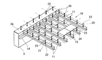
【解決手段】 クリーンルーム1の柱間に架設された大梁3の側面に、梁長手方向に沿って取り付けられた根太受け部材14と、対向する梁間に所定間隔をあけて配列して架設され、根太受け部材14上に着脱可能に固定されてフロア面を支持する根太構造を構成する根太部材11を設ける。フロア面に形成される新たな開口の寸法に合わせて根太部材11を移動して根太受け部材14に支持させ、所定開口を有する根太構造に変更する。
【選択図】 図2PROBLEM TO BE SOLVED: To provide a joist structure capable of easily installing openings of various sizes assumed in accordance with a specification change at a floor level of a clean room.
SOLUTION: A joist receiving member 14 attached along the longitudinal direction of a beam is arranged on a side surface of a large beam 3 installed between pillars of a clean room 1 and arranged with a predetermined interval between opposed beams. A joist member 11 constituting a joist structure that is detachably fixed on the receiving member 14 and supports the floor surface is provided. The joist member 11 is moved in accordance with the size of a new opening formed on the floor surface and supported by the joist receiving member 14 to change to a joist structure having a predetermined opening.
[Selection] Figure 2
Description
本発明はクリーンルーム用根太構造に係り、特にクリーンルームの床レベルにおける、仕様変更に伴って想定される様々な大きさの開口の設置を容易に行えるクリーンルーム用根太構造に関する。 The present invention relates to a joist structure for a clean room, and more particularly to a joist structure for a clean room that can easily install openings of various sizes assumed in accordance with a specification change at the floor level of the clean room.
クリーンルームでは、床構造を設計する場合、たとえば根太材を梁間に、所定の間隔(通常、600mm程度)をあけて架設し、その上に支柱ボルト等の支持部材を立設して配管、配線のための所定高さの空間を確保するとともに、エアの床吸い込みを実現するための多孔板やグレーチングからなるクリーンルーム用フロア材を敷設したフリーアクセスフロア構造とするのが一般的である。 In the clean room, when designing the floor structure, for example, a joist is installed between the beams with a predetermined interval (usually about 600 mm), and a support member such as a column bolt is erected on top of it. In general, a free access floor structure in which a clean room floor material made of a perforated plate or a grating is used to secure a space of a predetermined height for achieving air suction is provided.
ところで、クリーンルームでは、このフリーアクセスフロア上に種々の精密な製造機器類が設置される。そして、その製造ラインの変更に応じて適宜、床構造、特に根太材の配置を変更できるようにすることがクリーンルームの作業スペースを効率的に活用するために重要である。その点を考慮した発明として、特許文献1に開示された発明がある。 By the way, in a clean room, various precision manufacturing devices are installed on the free access floor. And, in order to efficiently use the work space of the clean room, it is important to be able to change the floor structure, particularly the arrangement of the joists, as appropriate according to the change of the production line. As an invention considering this point, there is an invention disclosed in Patent Document 1.
特許文献1では、機器類を設置することを念頭に、高剛性の根太と、高剛性の機械基礎床版とを固定ボルトで一体化させ、その上にフリーアクセスフロアパネルを敷設する構成の可動組立式の高剛性床基礎が開示されている。 In Patent Document 1, in consideration of installing equipment, a highly rigid joist and a highly rigid machine foundation floor slab are integrated with a fixing bolt, and a movable access floor panel is laid on top of it. A prefabricated high-rigidity floor foundation is disclosed.
特許文献1に開示された床構造は、高剛性根太上の機械基礎用床版を固定ボルトで一体化して、床剛性を高める方策が開示されている。このとき、高剛性根太は、大梁間に一体的に連結架設された小梁上に所定間隔をあけて配列されているため、小梁を避けた開口寸法までしかレイアウトの変更ができないという問題がある。このため、製造工程の変化に対応させたストッカーを設けたり、昇降階段等を設置するのが困難である。そこで、本発明の目的は上述した従来の技術が有する問題点を解消し、大梁の梁側面に根太の支持部を形成し、開口部の大きさを最大限、変更可能にできるようにしたクリーンルーム用根太構造を提供することにある。 The floor structure disclosed in Patent Document 1 discloses a measure for increasing floor rigidity by integrating a machine foundation floor slab on a highly rigid joist with fixing bolts. At this time, because the high rigidity joists are arranged at predetermined intervals on the small beams that are integrally connected between the large beams, there is a problem that the layout can only be changed up to the opening size avoiding the small beams. is there. For this reason, it is difficult to provide a stocker corresponding to a change in the manufacturing process, or to install an elevating staircase or the like. Accordingly, the object of the present invention is to solve the problems of the prior art described above, and to form a joist support portion on the beam side surface of the large beam so that the size of the opening can be changed to the maximum. To provide a joist structure.
上記目的を達成するために、本発明はクリーンルームの柱間に架設された大梁の側面に、梁長手方向に沿って取り付けられた根太受け手段と、対向する前記梁間に所定間隔をあけて配列して架設され、前記根太受け手段上に着脱可能に固定されてフロア面を支持する根太構造を構成する根太部材を備え、前記フロア面に形成される新たな開口の寸法に合わせて前記根太部材を移動して前記根太受け手段に支持させ、所定開口を有する根太構造に変更させることを特徴とする。 In order to achieve the above-mentioned object, the present invention arranges a joist receiving means attached along the longitudinal direction of a beam on a side surface of a large beam installed between columns of a clean room, and a predetermined interval between the opposed beams. A joist member that constitutes a joist structure that is removably fixed on the joist receiving means and supports the floor surface, and the joist member is adapted to the size of a new opening formed in the floor surface. It is moved, supported by the joist receiving means, and changed to a joist structure having a predetermined opening.
前記根太部材上にフロア材を支持する所定高さの脚部材を配列し、該脚部材上に前記フロア材を敷設して前記フロア面をフリーアクセスフロアとすることが好ましい。 It is preferable that leg members having a predetermined height for supporting a floor material are arranged on the joist member, and the floor material is laid on the leg member to make the floor surface a free access floor.
前記根太受け手段は、前記根太部材の上面が前記梁上面とレベルが一致するように、前記梁の側面に取り付けることが好ましい。 The joist receiving means is preferably attached to the side surface of the beam so that the upper surface of the joist member is level with the upper surface of the beam.
前記根太部材の端部を、前記根太受け手段に把持手段を介して着脱可能に固定することが好ましい。 It is preferable that the end of the joist member is detachably fixed to the joist receiving means through a gripping means.
本発明によれば、大梁の側面支持部で根太部材を支持し、この側面支持部の何れの位置でも各根太材を支持することができるようにしたので、クリーンルーム内の装置レイアウトの変更、ストッカーや製造機器のレイアウトの変更等によって必要となる、様々な面積の床開口部に適合した根太構造を、容易に構築できるという効果を奏する。 According to the present invention, the joist member is supported by the side support portion of the girder and each joist material can be supported at any position of the side support portion. In addition, there is an effect that it is possible to easily construct a joist structure suitable for floor openings of various areas, which is required by changing the layout of manufacturing equipment or the like.
以下、本発明のクリーンルーム用根太構造の実施するための最良の形態として、以下の実施例について添付図面を参照して説明する。 Hereinafter, as the best mode for carrying out the joist structure for a clean room of the present invention, the following examples will be described with reference to the accompanying drawings.
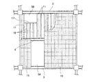
図1は、クリーンルーム1の4本の柱間2に敷設された床構造を模式的に示した床伏図である。本実施例では、柱2の柱芯間は9.6mに設定され、大梁3が架設され、さらに桁行方向のスパン中央位置に中間梁4が架設されている。図中、下半部は説明のために根太材11を配列した状態を示している。上半部には開口5が形成され、その他の床部分に根太材11が配列され、フリーアクセスフロアのためのフロア材15が敷設された状態(一部、根太材を表示のため図示省略)が示されている。図2は、根太材11が標準ピッチで配列された根太構造10上にフリーアクセスフロアが構築された構成を示した部分斜視図である。同図に示したように、根太構造10は、根太材11と、根太材11上に配列された脚部材としての支柱ボルト20と、支柱ボルト20のフロア受け部材23に支持されて敷設されたフロア材15とからなる。
FIG. 1 is a floor plan view schematically showing a floor structure laid between four
図1に示した根太構造10の詳細について図2を参照して説明する。図2に示したように、大梁3の側面の所定高さに根太受け材14としての溝形鋼が固着されている。この根太受け材14の取付位置は根太材11(本実施例では、たとえばH150×150)の高さ分に相当する寸法だけ梁上面から下げた位置に後施工アンカーを用いたボルト締め26により固定されている(図6参照)。また、本実施例では、図1下半部に示したように、張間方向に沿って600mm間隔をあけて根太材11が配列されている。各根太材11は、将来的に可動根太として機能しない場所では、根太受け材14にボルト固定してよい。また可動根太として、その設置位置を変更する可能性がある場合には、ボルト締め式のクランプ等の緊結金具25(図6参照)を用いて根太材11と根太受け材14とを固定することが好ましい。
Details of the
また、図2に示したように、フリーアクセスフロアを構成するために、脚部材としての支柱ボルト20が600mm×600mmのピッチで根太材11の上面に立設されている。この支柱ボルト20は、一実施例として用いられたフリーアクセスフロア用の脚部材で、ネジ調整により長さ調整可能な支柱21と、その上下にベースプレート22とフロア受け部材23とが一体的に取り付けられた組立既製品である。脚部材としては、フリーアクセスフロアの設計仕様に応じた高さを調整可能な支柱タイプの他、直置き用のベースプレートタイプ、耐震脚部材等を適宜採用することができる。
Further, as shown in FIG. 2, in order to constitute a free access floor, support
図2に示したように、各支柱ボルト20は隣接したフロア材15の四隅を1点で載置可能なフロア受け部材23を有し、1辺が600mmのフロア材15は、各支柱ボルト20を支点として根太材11表面から所定高さの空間24を確保して敷き詰められる。
As shown in FIG. 2, each
図3は、図1に示した開口5の根太構造10を模式的に示した部分斜視図である。同図に示したように、開口5の大きさに応じて、根太材11を撤去するか、開口5の端部部材として利用するために所定量だけ根太受け材14での支持位置をずらして利用する。このとき開口5の張間方向の寸法は、600mmの倍数とすることで、フロア材15は標準寸法材を使用することができる。端数が生じる場合には、所定寸法に切断したフロア材(図示せず)を開口周縁部に当てはめて使用することが好ましい。
FIG. 3 is a partial perspective view schematically showing the
図4は、根太材11を1スパン分取り除いて形成された開口5Aと、根太材11のスパンの一部に小開口5Bを設けた実施例を示した床構造を模式的に示した床伏図である。同図に示したように、小開口5Bが根太材11のスパン長より小さい場合には、端部に位置する根太材11間を繋ぐ小梁17を配置し、この小梁17に短い根太材18を連結させることで、開口5の周辺のフロア材15の敷設が行えるようにする。図5は、このような小開口5の周囲に配列された根太材11と、根太材11上に配列された支柱ボルトと、支柱ボルト20のフロア受け部材23(図5参照)上に敷設されたフロア材15(支柱ボルトとの関係を示すために一部のみ表示)とを示した斜視図である。本実施例では、小開口5の端部の根太材11に対して同サイズの小梁17をボルト連結したが、根太材11側の所定位置に吊り下げ式のブラケット(図示せず)等の支持手段を設け、このブラケットで小梁17を支持するようにしてもよい。
FIG. 4 is a floor plan schematically showing a floor structure showing an embodiment in which an opening 5A formed by removing one span of the
以上に述べたように、図2に示した標準ピッチで配列された根太材11を、たとえば図3,図5に示したように、設計上必要な開口5だけ取り除いたり、移動させたりするだけで、フロア上に所定の開口5を確保することができる。フロア上で比較的レイアウト変更の頻度が高い場合には、その都度、根太材11を撤去、搬入するのでは、作業が煩雑になるので、このような場合には支柱ボルト20の立設位置を避けた位置に根太材11を仮架設させておき、再度のレイアウト変更時の対応を容易にすることができる。
As described above, the
図6は、梁コンクリートに取り付けられた根太受け材14のフランジ14a上に根太材11の端部を固定した状態を示した部分拡大図である。同図に示したように、根太材11を可動部材とするためには、固定手段は簡易な構造の治具等であることが好ましい。そのため、本実施例では、ボルト締めクランプ金物25を使用している。なお、図示しないが、根太受け材14の上フランジ14aに所定間隔(たとえば200mm)に支持孔をあけておき、根太材11のフランジに設けた取付孔とを一致させてボルト締め固定することはクリールーム内での作業量の軽減につながる。このとき、根太受け材14に多数の孔が設けられるので、強度面の保証が得られる部材サイズを設定することが重要である。
FIG. 6 is a partially enlarged view showing a state in which the end portion of the
1 クリーンルーム
2 柱
3 大梁
4 中間梁
5,5A,5B 開口
10 根太構造
11,18 根太材
14 根太受け部材
15 フロア材
20 支柱ボルト
DESCRIPTION OF SYMBOLS 1
Claims (4)
Priority Applications (1)
| Application Number | Priority Date | Filing Date | Title |
|---|---|---|---|
| JP2007091071A JP4977514B2 (en) | 2007-03-30 | 2007-03-30 | Joist structure for clean room |
Applications Claiming Priority (1)
| Application Number | Priority Date | Filing Date | Title |
|---|---|---|---|
| JP2007091071A JP4977514B2 (en) | 2007-03-30 | 2007-03-30 | Joist structure for clean room |
Publications (2)
| Publication Number | Publication Date |
|---|---|
| JP2008248564A true JP2008248564A (en) | 2008-10-16 |
| JP4977514B2 JP4977514B2 (en) | 2012-07-18 |
Family
ID=39973827
Family Applications (1)
| Application Number | Title | Priority Date | Filing Date |
|---|---|---|---|
| JP2007091071A Active JP4977514B2 (en) | 2007-03-30 | 2007-03-30 | Joist structure for clean room |
Country Status (1)
| Country | Link |
|---|---|
| JP (1) | JP4977514B2 (en) |
Cited By (1)
| Publication number | Priority date | Publication date | Assignee | Title |
|---|---|---|---|---|
| JP7174873B1 (en) * | 2022-02-25 | 2022-11-17 | 日鉄建材株式会社 | Deck slab, deck slab construction method, and deck slab design method |
Citations (4)
| Publication number | Priority date | Publication date | Assignee | Title |
|---|---|---|---|---|
| JPS60192053A (en) * | 1984-03-14 | 1985-09-30 | 清水建設株式会社 | Floor structure in clean room |
| JPH0649947A (en) * | 1992-06-18 | 1994-02-22 | Misawa Homes Co Ltd | Fitting structure of ceiling panel |
| JPH10196087A (en) * | 1997-01-16 | 1998-07-28 | Matsumoto Kogyo Kk | Fastening hardware floor joist |
| JP2006037540A (en) * | 2004-07-28 | 2006-02-09 | Sekisui Chem Co Ltd | Unit building |
-
2007
- 2007-03-30 JP JP2007091071A patent/JP4977514B2/en active Active
Patent Citations (4)
| Publication number | Priority date | Publication date | Assignee | Title |
|---|---|---|---|---|
| JPS60192053A (en) * | 1984-03-14 | 1985-09-30 | 清水建設株式会社 | Floor structure in clean room |
| JPH0649947A (en) * | 1992-06-18 | 1994-02-22 | Misawa Homes Co Ltd | Fitting structure of ceiling panel |
| JPH10196087A (en) * | 1997-01-16 | 1998-07-28 | Matsumoto Kogyo Kk | Fastening hardware floor joist |
| JP2006037540A (en) * | 2004-07-28 | 2006-02-09 | Sekisui Chem Co Ltd | Unit building |
Cited By (1)
| Publication number | Priority date | Publication date | Assignee | Title |
|---|---|---|---|---|
| JP7174873B1 (en) * | 2022-02-25 | 2022-11-17 | 日鉄建材株式会社 | Deck slab, deck slab construction method, and deck slab design method |
Also Published As
| Publication number | Publication date |
|---|---|
| JP4977514B2 (en) | 2012-07-18 |
Similar Documents
| Publication | Publication Date | Title |
|---|---|---|
| KR100908266B1 (en) | Height adjuster for formwork with handle | |
| JP4977514B2 (en) | Joist structure for clean room | |
| KR101180845B1 (en) | Supporting System for Slab Form and Construction Method Using the Same | |
| JP6164479B2 (en) | Underground pit structure | |
| JP4221935B2 (en) | Double floor structure | |
| KR200268196Y1 (en) | A supporting block unit for mounting floor panels of clean room | |
| JP5940404B2 (en) | Construction method of beam members | |
| JP5456403B2 (en) | Clean room floor structure and construction method | |
| JP2018066115A (en) | Field edge fixing member, suspended ceiling structure, and method for constructing suspended ceiling structure | |
| JP6252834B2 (en) | Underground pit structure | |
| JP2020002657A (en) | Construction method of building foundation | |
| KR101101182B1 (en) | Reverse drilling method of underground structure | |
| JP2019044362A (en) | Construction method of src beam and formwork support structure of src beam | |
| JP5961145B2 (en) | Equipment installation structure of passenger conveyor | |
| KR200378490Y1 (en) | Supporting plate fixing apparatus of a clean-room | |
| JP7723386B2 (en) | Slab vibration reduction structure | |
| JP4041454B2 (en) | Support and cover member used for this | |
| JP7823643B2 (en) | Column beam joint structure | |
| JP4460377B2 (en) | Clean room joists and clean room joists using the same | |
| JP6210768B2 (en) | Structure | |
| JP5133184B2 (en) | Free access floor mount | |
| KR100371219B1 (en) | Strenghen structure of access floor for clean room | |
| JP2009161914A (en) | Pedestal for free access floor | |
| JP4006991B2 (en) | Double floor structure | |
| KR100728824B1 (en) | Formwork Support for Building |
Legal Events
| Date | Code | Title | Description |
|---|---|---|---|
| A621 | Written request for application examination |
Free format text: JAPANESE INTERMEDIATE CODE: A621 Effective date: 20100309 |
|
| TRDD | Decision of grant or rejection written | ||
| A01 | Written decision to grant a patent or to grant a registration (utility model) |
Free format text: JAPANESE INTERMEDIATE CODE: A01 Effective date: 20120410 |
|
| A01 | Written decision to grant a patent or to grant a registration (utility model) |
Free format text: JAPANESE INTERMEDIATE CODE: A01 |
|
| A61 | First payment of annual fees (during grant procedure) |
Free format text: JAPANESE INTERMEDIATE CODE: A61 Effective date: 20120416 |
|
| R150 | Certificate of patent or registration of utility model |
Ref document number: 4977514 Country of ref document: JP Free format text: JAPANESE INTERMEDIATE CODE: R150 Free format text: JAPANESE INTERMEDIATE CODE: R150 |
|
| FPAY | Renewal fee payment (event date is renewal date of database) |
Free format text: PAYMENT UNTIL: 20150420 Year of fee payment: 3 |
|
| S111 | Request for change of ownership or part of ownership |
Free format text: JAPANESE INTERMEDIATE CODE: R313111 |
|
| R350 | Written notification of registration of transfer |
Free format text: JAPANESE INTERMEDIATE CODE: R350 |
|
| R250 | Receipt of annual fees |
Free format text: JAPANESE INTERMEDIATE CODE: R250 |
|
| R250 | Receipt of annual fees |
Free format text: JAPANESE INTERMEDIATE CODE: R250 |
|
| R250 | Receipt of annual fees |
Free format text: JAPANESE INTERMEDIATE CODE: R250 |
|
| S531 | Written request for registration of change of domicile |
Free format text: JAPANESE INTERMEDIATE CODE: R313531 |
|
| R350 | Written notification of registration of transfer |
Free format text: JAPANESE INTERMEDIATE CODE: R350 |
|
| R250 | Receipt of annual fees |
Free format text: JAPANESE INTERMEDIATE CODE: R250 |