JP2008246661A - Assembly apparatus for strut assembly - Google Patents
Assembly apparatus for strut assembly Download PDFInfo
- Publication number
- JP2008246661A JP2008246661A JP2007095002A JP2007095002A JP2008246661A JP 2008246661 A JP2008246661 A JP 2008246661A JP 2007095002 A JP2007095002 A JP 2007095002A JP 2007095002 A JP2007095002 A JP 2007095002A JP 2008246661 A JP2008246661 A JP 2008246661A
- Authority
- JP
- Japan
- Prior art keywords
- spring
- movable
- base
- assembly
- rod
- Prior art date
- Legal status (The legal status is an assumption and is not a legal conclusion. Google has not performed a legal analysis and makes no representation as to the accuracy of the status listed.)
- Granted
Links
Images


Abstract
Description
本発明は、車両の懸架装置として使用されるストラットアッセンブリの組立装置に関する。 The present invention relates to a strut assembly assembling apparatus used as a vehicle suspension apparatus.
車両は懸架装置により車両が受ける路面反力を軽減している。この懸架装置は車体と車軸支持部材との間を連結すると共に車輪を所定の整列状態に保持するリンク系と、路面反力を干渉しつつ車体荷重を支持するスプリングと、路面反力に基づく車体振動を吸収し減衰させるショックアブソーバーとを装備しており、特に、スプリングとショックアブソーバーとを一部品化したストラットアッセンブリが多用されている。 The vehicle reduces the road surface reaction force received by the vehicle by the suspension device. This suspension device connects a vehicle body and an axle support member and holds a wheel in a predetermined alignment state, a spring that supports a vehicle body load while interfering with the road surface reaction force, and a vehicle body based on the road surface reaction force It is equipped with a shock absorber that absorbs and dampens vibrations. In particular, a strut assembly in which a spring and a shock absorber are made into one part is often used.
このストラットアッセンブリは、ショックアブソーバーの外筒外周にスプリングを外嵌させ、そのスプリング下部が外筒外壁に溶着されたロアブラケットに係止され、スプリングの上部がロッド端にボルト止めされているアッパブラケットに係止される。通常、ロッド端とボルト止めされたアッパブラケットは、車体側受け板下面にボルト止めされ、外筒下端が車軸支持部材側に連結される。これにより、車軸支持部材側から入力された路面反力がスプリングの弾性変位により吸収され、スプリング振動がショックアブソーバーの内部の減衰処理部に伝わり、減衰されている。 This strut assembly is an upper bracket in which a spring is fitted on the outer cylinder outer periphery of the shock absorber, the lower part of the spring is locked to the lower bracket welded to the outer wall of the outer cylinder, and the upper part of the spring is bolted to the rod end. It is locked to. Usually, the upper bracket bolted to the rod end is bolted to the lower surface of the vehicle body side receiving plate, and the lower end of the outer cylinder is connected to the axle support member side. As a result, the road surface reaction force input from the axle support member side is absorbed by the elastic displacement of the spring, and the spring vibration is transmitted to the damping processing portion inside the shock absorber and is damped.
このようなストラットアッセンブリの組立の際にはストラットアッセンブリ組立装置が使用されている。その一例として、組立前に基枠に固定された外筒よりロッド上端を機械的に引き出し、その上端にアッパブラケット等を嵌着後にナット止めするという組立装置が実公昭60−12788号公報(特許文献1)に開示されている。
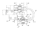
ところで、図11に示すような組立装置では、不図示の底部基枠に支持された受台100にストラットアッセンブリ110の下端部を載置し、不図示の低部基枠より上方に延びる縦柱部に支持されたショックアブソーバー挟持部120によりショックアブソーバーの下側部を挟持し、これによって組立前のストラットアッセンブリ110を縦向きに支持している。
In assembling such a strut assembly, a strut assembly assembling apparatus is used. As an example, an assembly device in which the upper end of the rod is mechanically pulled out from an outer cylinder fixed to the base frame before assembly, and an upper bracket or the like is fitted to the upper end of the rod and then fastened with a nut is disclosed in Japanese Utility Model Publication No. 60-12788. Document 1).
By the way, in the assembling apparatus as shown in FIG. 11, the lower end of the
更に、この組立装置は、不図示の縦柱部の上部に可動台130が上下動可能に支持され、可動台の中央にアッパブラケット140の支持部150を設け、このブラケット支持部150より左右に延びる左右水平台部160を設け、これによりスプリング170を係止可能な左右スプリング押え部材180を移動可能に支持している。
ここで、可動台130を降下作動させると左右のスプリング押え部材180がスプリング170を圧縮し、相対的にロッド190上端が上方に突き出す。この際、可動台130の中央のアッパブラケットの取り付け穴には緩衝部材200が取り付けられており、その中央穴h1にロッド上端の螺子部191が貫通される。更に、螺子部191には不図示のナットが螺着され、これによってストラットアッセンブリ110の上端部の組立が成されている。
Further, in this assembling apparatus, a
Here, when the
ところが、可動台130側を降下作動させた際に、受台100及びショックアブソーバー挟持部120に下部が支持されたストラットアッセンブリ110の上部が傾き、芯ずれを起す場合がある。このようにストラットアッセンブリの中心線Laと、可動台130に支持されているアッパブラケット140上の緩衝部材200の中心穴h1とがずれると、ロッド上端の螺子部191がアッパブラケット140上の緩衝部材200と干渉し、その緩衝部材200をアッパブラケット上より落下(図11中の2点鎖線参照)させてしまい、作業性の低下を招くこととなる。
However, when the
更に、ロッド上端にナット(不図示)が螺着された後で、左右のスプリング押え部材180を開放位置(左右に開いた状態)に切換えると、スプリングが圧縮開放するが、この際、スプリング170が不安定に拡張変位し、スプリング外周面と左右のスプリング押え部材180とがすれ、スプリング170が傷付き易い。
しかも、スプリング170の圧縮開放時の瞬間的な復元変位方向は、スプリングの巻数、押え力、左右のスプリング押え部材180から外れる僅かなタイミング等により異なり、真垂直の方向に変位するとは限らず、不安定であり、アッパブラケット140のバネ受けであるスプリングアッパーパッド210よりはみ出しやすい。あるいは、スプリングアッパーパッド210がスプリング170の上端と一体化されている場合、そのスプリングアッパーパッド210がアッパブラケット140の正規の位置よりずれを生じやすく、改善が望まれている。
Further, after the nut (not shown) is screwed to the upper end of the rod, when the left and right
In addition, the instantaneous restoring displacement direction when the
本発明は、上述の問題点に着目してなされたもので、ショックアブソーバーのロッド上端とアッパブラケット上の緩衝部材との組立作業性を向上させることが出来るストラットアッセンブリ組立装置を提供することにある。
更に、ストラットアッセンブリ組立時のスプリングの傷付き防止や、スプリングアッパーパッドよりのスプリングのはみ出し、あるいは、スプリングアッパーパッドの正規位置よりのずれを防止できるストラットアッセンブリ組立装置を提供することにある。
The present invention has been made paying attention to the above-mentioned problems, and provides a strut assembly assembling apparatus capable of improving the assembling workability between the upper end of the rod of the shock absorber and the buffer member on the upper bracket. .
It is another object of the present invention to provide a strut assembly assembling apparatus capable of preventing the spring from being damaged when assembling the strut assembly, preventing the spring from protruding from the spring upper pad, or preventing the spring upper pad from shifting from the normal position.
上述の目的を達成するために、請求項1の発明は、基枠の底部に取り付けられると共にショックアブソーバーを縦向きで支持する受台と、前記基枠の縦柱部に上下動可能に支持される可動台と、同可動台の上端部に上下動可能に支持されたナットランナーとを具備し、前記受台は前記ショックアブソーバーの下部を支持する外筒支持部を備え、前記可動台は可動本体と、同可動本体より延出し前記受台の縦向き中心線上に前記ストラットアッセンブリのアッパブラケットを支持するブラケット支持部と、同ブラケット支持部より左右に延びる左右水平台部と、左右水平台部に支持され前記受台の縦向き中心線に対して接離する方向に摺動自在な左右摺動台とを備え、前記左右摺動台はその下部に前記スプリングを係止可能な左右スプリング押え部材を備え、その上部に前記縦向き中心線上に位置するよう前記ロッドを摺動可能に挟むロッド位置決め部材を備え、前記受台に対して可動台を接近方向に変位させることで、前記左右スプリング押え部材がスプリングを圧縮させ、左右ロッド位置決め部材により位置規制されたロッドの上端部を前記アッパブラケットの中央穴に貫通させ、前記上端部に前記ナットランナーによりナットを締結する、ことを特徴とする。
In order to achieve the above-mentioned object, the invention of
請求項2の発明は、請求項1に記載のストラットアッセンブリ組立装置において、前記左右スプリング押え部材は、その下部に前記スプリングを係止する係止位置とスプリングと摺接しつつその上方移動を許容する第1開放位置とスプリングより離脱する第2開放位置とに切換え可能に前記左右摺動台に取付けられ、前記螺子部にナットが締結されると、前記ロッド位置決め部材を開放作動させ、更に、前記左右スプリング押え部材を第1開放位置に切換え、その後、第2開放位置に切換える、ことを特徴とする。 According to a second aspect of the present invention, in the strut assembly assembling apparatus according to the first aspect, the left and right spring pressing members allow an upward movement while being in sliding contact with a spring and a locking position for locking the spring at a lower portion thereof. When the nut is fastened to the screw part so as to be switchable between a first open position and a second open position separated from the spring, the rod positioning member is opened, The left and right spring pressing members are switched to the first opening position and then switched to the second opening position.
請求項3の発明は、請求項1又は2に記載のストラットアッセンブリ組立装置において、左右スプリング押え部材はスプリングの外周縁に摺接する部位が樹脂で形成される、ことを特徴とする。 According to a third aspect of the present invention, in the strut assembly assembling apparatus according to the first or second aspect, the left and right spring pressing members are formed of resin at a portion that is in sliding contact with the outer peripheral edge of the spring.
請求項1記載の発明によれば、前記受台に対して可動台を接近変位させ、これにより係止位置の左右スプリング押え部材がスプリングを圧縮させ、同時に左右ロッド位置決め部材により位置規制されたロッドの上端側の螺子部を前記アッパブラケット側に突き出し変位させ、この際、左右ロッド位置決め部材により位置規制されたロッドの上端は前記受台の中心線の上方延長部よりずれることが無いので、確実にアッパブラケットの中央穴に貫通することができ、アッパブラケットが位置ずれしたロッドに干渉して取り付け穴から落下するという事態の発生を防止でき、組付け作業性が向上する。 According to the first aspect of the present invention, the movable base is moved closer to the receiving base, whereby the left and right spring pressing members in the locking position compress the spring, and the position is restricted by the left and right rod positioning members at the same time. At this time, the upper end of the rod whose position is regulated by the left and right rod positioning members is not displaced from the upper extension of the center line of the cradle. Therefore, it is possible to prevent the situation where the upper bracket interferes with the misaligned rod and falls from the mounting hole, and the assembling workability is improved.
請求項2記載の発明によれば、左右スプリング押え部材を係止位置より第1開放位置に切換え、これによって、左右スプリング押え部材がスプリングの外周縁に摺接する状態でその上方移動を許容することができる。このため、左右スプリング押え部材にスプリングガイド機能を持たせることができ、スプリングの圧縮開放時の不安定な弾性変位を規制でき、スプリングの上端がアッパブラケットのバネ受けであるスプリングアッパーパッドよりはみ出すことを確実に防止でき、あるいは、スプリングアッパーパッドがスプリングの上端と一体化されている場合、そのスプリングアッパーパッドがアッパブラケットのバネ受け位置よりずれることを確実に防止でき、この点からも組付け作業性が向上する。 According to the second aspect of the present invention, the left and right spring pressing members are switched from the locking position to the first opening position, thereby allowing the left and right spring pressing members to move upward while being in sliding contact with the outer peripheral edge of the spring. Can do. For this reason, the left and right spring pressing members can be provided with a spring guide function, can regulate unstable elastic displacement when the spring is compressed and released, and the upper end of the spring protrudes beyond the spring upper pad that is the spring bracket of the upper bracket. If the spring upper pad is integrated with the upper end of the spring, it can be reliably prevented that the spring upper pad is displaced from the spring receiving position of the upper bracket. Improves.
請求項3記載の発明によれば、左右スプリング押え部材のスプリングの外周縁に摺接するワーク接触面が樹脂で形成されたので、スプリングの傷付をなくすことができる。しかも、ワーク接触面を形成する部位が樹脂製で、その樹脂性部位以外の部分をスプリング反力、衝撃に耐えうる鋼鉄製の金具とすることで左右スプリング押え部材の耐久性の低下を防止できる。 According to the third aspect of the present invention, since the work contact surface that is in sliding contact with the outer peripheral edge of the spring of the left and right spring pressing member is formed of resin, it is possible to eliminate damage to the spring. In addition, the part that forms the workpiece contact surface is made of resin, and the parts other than the resinous part are made of steel fittings that can withstand spring reaction force and impact, thereby preventing deterioration of the durability of the left and right spring retainer members. .
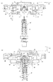
図1、図2にはこの発明の一実施形態としてのストラットアッセンブリ組立装置を示した。
このストラットアッセンブリ組立装置はフロア面Aに載置される底基枠2と、同底基枠2の一端より垂直方向に延びる縦柱状の縦基枠3とから成る基枠1を備える。ここで、底基枠2にはショックアブソーバー4を縦向きで支持する受台5が取り付けられ、縦基枠33に可動本体6を有した可動台7が上下動可能に支持され、可動本体6の上端部の縦レール8に上下動可能にナットランナー9が支持されている。
底基枠2の上向面にはショックアブソーバー4を縦向きで支持する受台5を有したストラット取り付け台11と、荷重受け部材12とが装着される。
1 and 2 show a strut assembly assembling apparatus as an embodiment of the present invention.
This strut assembly assembling apparatus includes a
A strut mounting base 11 having a
ストラット取り付け台11にはその表裏2つの縦壁面にストラット装着部13がそれぞれ設けられる。ストラット取り付け台11は駆動部収納台14の上で縦向き回転中心線L1回りに回転可能に支持されている。なお、駆動部収納台14内の取り付け台駆動部15は後述の制御手段16によって適時に切換え回動制御され、ストラット装着部13のいずれか一方が縦基枠3側に対向するように切換え、保持する。
各ストラット装着部13はストラット取り付け台11が駆動部収納台14によって180°毎に切換え回転され、その際、縦基枠3と対向する組立位置K1においてはストラットの組立を可能とし、更に180°回転して組立前位置K2に達すると、ストラット装着部13に新たな組立前のストラットの組み込みがなされている。
各ストラット装着部13は、ストラット取り付け台11の縦壁より所定量突き出た受台5と、その受台5より所定量上方の外筒保持部17と、その外筒保持部17より所定量上方のスプリング保持部18とを備え、これらによりストラットを縦向きの縦中心線に沿って支持する。
The strut mounting base 11 is provided with
In each
Each
受台5はその上向き面に、ショックアブソーバー4の下端に溶着された円筒状の車軸連結部19をずれなく載置する凹溝部21が形成され、その凹溝部21の直下に低壁面22が形成される。この低壁面22は荷重受け部材12の上端当接部121に当接可能に形成される。荷重受け部材12は受台5及びその上のストラットM’の下方変位を阻止するもので、ストラット取り付け台11が駆動部収納台14によって180°回転される毎に退却位置E0(図1に2点鎖線で示す位置)から当接位置E1(図1に実線で示す位置)にエアーシリンダ23の高圧エアの給排切換えによって切換え保持される。エアーシリンダ23には不図示のエア源がエア切換え用の切換えバルブ231を介して連結され、切換えバルブ231は後述の制御手段16によって適時に切換えられる。
The
外筒保持部17は、ストラット取り付け台11の縦壁より所定量突き出た腕部171と、腕部の内部に基端側をピン結合すると共に回動端側がショックアブソーバー4の外筒底部を挟持可能な一対の湾曲把持部材172と、ストラット取り付け台11内に配備されると共に一対の湾曲把持部材172を基端側を中心にして水平面方向に把持作動させる駆動部173とを備える。
スプリング保持部18は、ストラット取り付け台11の縦壁上部に設けられる縦レール24にガイドされ、エアーシリンダ25により高さ位置を適宜切換え可能な昇降枠26と、昇降枠26に支持されスプリング27を挟持可能な一対のスプリング把持部材28と、スプリング把持部材28をその基端側を中心にして水平面方向に所定の弾性力で把持作動させる不図示の弾性力付与部材とを備える。エアーシリンダ25には不図示のエア源が連結され、不図示の切換えバルブが後述の制御手段16によって適時に切換えられることで、昇降枠26の高さ位置を適宜切換え可能としている。
The outer
The spring holding portion 18 is guided by a vertical rail 24 provided on the upper portion of the vertical wall of the strut mounting base 11, and a
このような受台5と外筒保持部17とスプリング保持部18とを備える各ストラット装着部13は、縦基枠3と対向する組立位置K1とその反対側の組立前位置K2との間を交互に回転移動する。組立位置K1で組立が完了したストラットアッセンブリMを組立前位置K2で取り外し、そのストラット装着部13に新たな組立前ストラットM’を縦向きの縦中心線L0に沿って取り付けている。
一方、ストラット取り付け台11と対向配備された縦基枠3は、その一側面に縦支持レール8が取り付けられ、ここに可動台7の可動本体6が上下動可能に支持される。この縦基枠3の他側面にはスプリング圧縮昇降駆動モータ35(以後単に主モータと記す)が取り付けられる。この主モータ35の回転力は縦支持レール8に併設される送りねじ軸36に無端ベルト37を介して伝達されている。
縦支持レール34内の送りねじ軸36は可動本体6側に支持された不図示の送りねじ部材に螺合しており、送りねじ軸36の正逆回転に応じて可動本体6側を上下に移動でき、これらが昇降駆動部を成している。
Each
On the other hand, the vertical base frame 3 arranged opposite to the strut mounting base 11 has a
The
可動本体6の上部には縦支持レール34が設けられ、ここにナットランナー9が支持され、下部にはアッパブラケット37を支持するブラケット支持部38が延出形成される。
A vertical support rail 34 is provided at the upper portion of the movable body 6, and the nut runner 9 is supported here, and a
ナットランナー9は電動の縦送り機構によって退却位置H1と締結位置H2とに上下移動でき、締結位置H2ではエア圧を駆動源としてナットnをストラットアッセンブリMの上部のロッド39に螺着するよう作動できる。
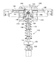
図7に示すように、ブラケット支持部38は可動本体6の下部より延出する中央基板41とその下部に突き出し調整可能に支持枠42が突設されている。図7、図2に示すように、支持枠42にはアッパブラケット37側の締結用ボルト371の挟持穴421が複数形成される。この挟持穴421にアッパブラケット側の締結用ボルト371を押込むことで、ずれなく締結用ボルト371を把持し、アッパブラケット37側を縦中心線L0上に支持できる。
The nut runner 9 can be moved up and down by the electric vertical feed mechanism to the retreat position H1 and the fastening position H2. At the fastening position H2, the nut n is operated to be screwed onto the
As shown in FIG. 7, the
図7に示すように、ブラケット支持部38の支持枠42の左右端より左右に左右水平台部43が延出形成される。
左右水平台部43には左右の水平レール44が設けられ、ここに左右摺動台45が取り付けられる。左右摺動台45は2段に直結したエアーシリンダ46により駆動される。左右摺動台45にはその下部に左右のスプリング押え部材47が互いに接離可能に取り付けられ、その上方に左右のロッド位置決め部材48が設けられる。
As shown in FIG. 7, left and right
The left and right
左右の各スプリング押え部材47は、図2,3に示すように、左右摺動台45に固着される外枠49と、その内方に一体結合される内枠51と、内枠51に押さえ片52によって一体的に締め付け結合された樹脂片53と、を供える。左右の各スプリング押え部材47の各外枠49及び内枠51はその縦中心線L0と対向する側に下向きのバネ受け部hが凹状に形成される。図3に示すように、左右の各スプリング押え部材47は係止位置C0と第1、第2開放位置C1、C2とに切換え移動できる。係止位置C0では左右凹部が接近することで下向きのバネ受け部hを形成し、スプリング27の上端を係止できる。
As shown in FIGS. 2 and 3, the left and right
左右の各内枠51にはその縦中心線L0と対向する側に一対の樹脂片53が締結されている。この一対の樹脂片53は左右の各スプリング押え部材47が係止位置C0より第1開放位置C1に達した際に、図3に示すように、摺接面f1がスプリング27の外周面に摺接し、その上方移動を許容する位置に保持される。この左右の各スプリング押え部材47が第1開放位置C1に保持されることで、摺接面f1が弾性変位するスプリング27の縦中心線L0に対するずれを規制できる。即ち、スプリングガイド機能を持たせることができ、スプリング27の圧縮開放時の不安定な弾性変位を規制し、スプリング27の上端がアッパブラケット37のバネ受けであるスプリングアッパーパッド55よりはみ出すことを確実に防止できる。
A pair of
スプリング押え部材47の上方に左右のロッド位置決め部材48が設けられる。図4、図6(a)〜(c)に示すように、左右のロッド位置決め部材48は左右摺動台45に固着される左右エアーシリンダ56(図7参照)を駆動源とし、これにより左右挟持爪57を相対的に接離作動する。
ここで、左右挟持爪57は内枠51に形成される直状ガイド溝511(図4参照)に沿って摺動し、退却位置N1(図7(a)参照)と挟持位置N2(図7(b)参照)とに切換え駆動できる。左右挟持爪57は挟持位置N2(図7(b)参照)において、ロッド39の上端部を縦中心線L0上に位置するように左右よりがたなく、摺動可能に挟む。即ち、左右挟持爪57は挟持位置N2においてロッド39の上端の上下摺動を許容できる程度のゆるい挟持状態を保持するように形成されている。
Left and right
Here, the left and right clamping
ここで、スプリング押え部材47の駆動源である左右エアーシリンダ56と、スプリング押え部材47の駆動源である2段直結したエアーシリンダ46とには、複数のエアパイプp1、p2が接続される。同複数のエアパイプp1、p2はブラケット支持部38、可動本体6、フレキシブルパイプ58(図1参照)を経て、不図示のエア源側に連結される。しかも、図1に2点鎖線で示すように、左右エアーシリンダ56や2段直結したエアーシリンダ46の切換え制御弁Vも不図示の引き出し線を介して制御手段16に接続される。
このようなストラットアッセンブリ組立装置の作動を制御手段16の制御機能と共に説明する。
Here, a plurality of air pipes p <b> 1 and p <b> 2 are connected to the left and
The operation of such a strut assembly assembly apparatus will be described together with the control function of the control means 16.
なお、前以て、組立前のストラットM’がストラット取り付け台11の組立前位置K2に対向する側のストラット装着部13に取り付けられ、更に、可動台7のブラケット支持部38には、アッパブラケット37の上部中心穴Inが縦中心線L0上に位置するように取り付けられている。
その上で作業者による組立開始指令を受けると制御手段16が組立作動を開始する。
In addition, the strut M ′ before assembly is attached to the
Then, when the assembly start command is received from the operator, the control means 16 starts the assembly operation.
ここで組立開始指令を受けると、その時点で、ストラット取り付け台11が180°回転し、図1に示すように、ブラケット支持部38が組立位置K1に対向する。この際、ブラケット支持部38の受台5の低壁面22に荷重受け部材12が当接するように配備され(E1位置)、これによって、以後のスプリング圧縮時の荷重により受台5が上下変位することを防止できる。
When an assembly start command is received here, at that time, the strut mounting base 11 rotates 180 °, and the
この初期位置においては、図7(a)に示すように、可動台7が初期位置である退却位置R0に保持され、左右のスプリング押え部材47が第2開放位置C2に保持され、左右のロッド位置決め部材48が退却位置N1に保持されている。
次いで、図7(b)に示すように、制御手段16によって可動台7が退却位置R0から組み込み位置R1に降下移動され、次いで、左右のスプリング押え部材47が挟持位置C0に保持され、左右のロッド位置決め部材48が挟持位置N2に保持されるとする。
これにより、ロッド39の縦中心線L0からのずれが排除され、左右のスプリング押え部材47の下面に下向きのバネ受け部hが凹状に形成される。
In this initial position, as shown in FIG. 7 (a), the movable base 7 is held at the retracted position R0, which is the initial position, the left and right
Next, as shown in FIG. 7B, the movable base 7 is moved down from the retracted position R0 to the assembling position R1 by the control means 16, and then the left and right
Thereby, the deviation of the
次いで、図8(a)に示すように、制御手段16が可動台7を組み込み位置R1から貫通位置R2に降下移動させる。この際、左右のスプリング押え部材47の下向きのバネ受け部hにスプリング27の上端部が嵌合できる。同時に、左右のロッド位置決め部材48の働きで、アッパブラケット37に取り付けられる緩衝部材IのカラーI1の中心穴Inが縦中心線L0と一致している。このため、縦中心線L0に沿って上昇するロッドの上端部のねじ部はカラーI1等と相互干渉することなく、中心穴Inを貫通して、上方にねじ部を位置させることが出来、この際、ねじ部が緩衝部材Iと当接して、緩衝部材Iが落下し、貫通工程が誤作動となることを防止できる。
Next, as shown in FIG. 8A, the control means 16 moves the movable base 7 downward from the assembling position R1 to the penetrating position R2. At this time, the upper ends of the
次いで、図8(b)に示すように、制御手段16が可動台7を貫通位置R2より締結位置R3に更に押圧され、その状態に保持される。この状態で、制御手段16はナットランナー9を退却位置H1より締結位置H2に降下移動させ、締結位置H2でナットランナー9を締結駆動させる。この際、ナットランナー9はエア圧を駆動源としてナットnをストラットアッセンブリMの上部のロッド39のねじ部に螺着し、スプリング上端を当接させたアッパブラケット37をロッド39の上端に締結できる。
次いで、左右のロッド位置決め部材48が退却位置N1に切換えられ、更に、左右のスプリング押え部材47が第1開放位置C1に切換え保持される。この際、図3に示すように、左右の各スプリング押え部材47と一体の各樹脂片53の摺接面f1が弾性復帰変位するスプリング27の外周面に摺接し、その上方移動を許容すると共に、縦中心線L0に対するずれを規制できる。
Next, as shown in FIG. 8B, the control means 16 further presses the movable base 7 from the penetrating position R2 to the fastening position R3 and is held in that state. In this state, the control means 16 moves the nut runner 9 downward from the retreat position H1 to the fastening position H2, and drives the nut runner 9 to be fastened at the fastening position H2. At this time, the nut runner 9 can fasten the
Next, the left and right
即ち、各樹脂片53の摺接面f1(図3参照)にスプリングガイド機能を持たせることができ、スプリング27の圧縮開放時の不安定な弾性変位を規制できる。このため、スプリング27の上端がアッパブラケット37のバネ受けであるスプリングアッパーパッド55よりはみ出すことを確実に防止できる。
次いで、図8(c)に示すように、制御手段16が左右のスプリング押え部材47を退却位置N1に、左右摺動台を第2開放位置C2に切換え、ナットランナー9を退却位置H1に引き上げる。その後、制御手段16が可動台7を締結位置R3から退却位置R0に引き上げ作動させる。
この後、制御手段16はストラット取り付け台11を180°回転させ、組立完了のストラットアッセンブリMを組立前位置K2に対向させる。
That is, the sliding contact surface f1 (see FIG. 3) of each
Next, as shown in FIG. 8C, the control means 16 switches the left and right
Thereafter, the control means 16 rotates the strut mounting base 11 by 180 ° so that the assembled strut assembly M faces the pre-assembly position K2.
この際、すでに次の組立前のストラットM’がストラット取り付け台11の他方のブラケット支持部38に取付け済みであり、次の組立指令の入力を待つこととなる。
このように、図1のストラットアッセンブリ組立装置によれば、同時に左右ロッド位置決め部材48により位置規制されたロッド39の上端側の螺子部391をアッパブラケット37側に突き出し変位させ、この際、左右ロッド位置決め部材48により位置規制されたロッド39の上端は縦中心線L0よりずれることが無いので、確実にアッパブラケット37の取り付け穴に取り付けられた緩衝部材Iの中央穴Inに貫通することができ、取り付け穴に取り付けられた緩衝部材Iが位置ずれしたロッド39に当接して取り付け穴から落下するという事態の発生を防止でき、組付け作業性が向上する。
At this time, the next pre-assembly strut M ′ has already been attached to the other
As described above, according to the strut assembly assembling apparatus of FIG. 1, the
更に、左右スプリング押え部材47にスプリングガイド機能を持たせることができ、スプリング27の上端がアッパブラケット37のスプリングアッパーパッド55よりはみ出すことを確実に防止できる。更に、左右スプリング押え部材47のスプリング27の外周縁に摺接するワーク接触面が樹脂で形成されたので、スプリング27の傷付をなくすことができる。しかも、ワーク接触面を形成する部位が樹脂製で、その樹脂部以外の部分をスプリング反力、衝撃に耐えうる鋼鉄製の金具とすることで左右スプリング押え部材47の耐久性の低下を防止できる。
Further, the left and right
上述のところにおいて、組立前のストラットM’に組み付けられるアッパブラケット37にはそのバネ受け部内にスプリングアッパーパッドを前以て装備し(図7(a)参照)、これに対してスプリング27の上端が当接するように組立いた。
これに対して、図9(a)〜図10(c)には、予め、スプリング27の上端にスプリングアッパーパッド55’を前以て装備し、これをアッパブラケット37のバネ受け部内に嵌合させるように組立る実施形態を示した。なお、組立前のアッパブラケット37のバネ受け部内からはスプリングアッパーパッド55が排除されており、
ここでは、図7(a)〜図8(c)における場合と比較し、組立工程における相違点が少なく、重複説明を略す。ここでは、図9(a)で可動部7を初期状態の退却位置R0に保持し、図9(b)で可動部7を組み込み位置R1に降下移動し、図10(a)では可動台を貫通位置R2に降下移動させる。更に、図10(b)では可動台7を貫通位置R2に降下移動させる。更に、図10(b)では可動台を締結位置R3にまで降下させ、ナットnをロッド39の螺子部391に螺着させ、次いで、図10(c)では組立完了のストラットアッセンブリMより左右ロッド位置決め部材48及び左右スプリング押え部材47をそれぞれ退却位置に切換え、ストラットアッセンブリMの取り出しを可能としている。
In the above description, the
On the other hand, in FIGS. 9A to 10C, the upper end of the
Here, there are few differences in an assembly process compared with the case in FIG. 7 (a)-FIG.8 (c), and duplication description is abbreviate | omitted. Here, the movable part 7 is held at the retreat position R0 in the initial state in FIG. 9A, the movable part 7 is moved down to the assembly position R1 in FIG. 9B, and the movable base is moved in FIG. 10A. Move down to the penetrating position R2. Further, in FIG. 10B, the movable base 7 is moved down to the penetrating position R2. Further, in FIG. 10 (b), the movable base is lowered to the fastening position R3, and the nut n is screwed onto the
ここで、図7(a)〜図8(c)に示す工程での処理に対しての相違点は、図10(b)における貫通位置R2での作動にある。この工程では、制御手段16が可動台7を貫通位置R2に保持したまま、左右のロッド位置決め部材48を退却位置N1に切換え、更に、左右のスプリング押え部材47を第1開放位置C1に切換える。
Here, the difference with respect to the process in the steps shown in FIGS. 7A to 8C is the operation at the penetration position R2 in FIG. 10B. In this step, the control means 16 switches the left and right
この際、第1開放位置C1に保持された左右の各樹脂片53の摺接面f1と弾性復帰変位するスプリング27上端のスプリングアッパーパッド55の外周面とが摺接する。
その上で、スプリングアッパーパッド55がアッパブラケットのバネ受け部内に嵌合する。この場合も、摺接面f1にスプリングガイド機能を持たせることができ、縦中心線L0に対するスプリングアッパーパッド55のずれを規制でき、バネ受け部内の正規の位置にスプリングアッパーパッド55を取付けできる。
At this time, the sliding contact surface f1 of each of the left and
Then, the spring
なお、図9(a)〜図10(c)のストラットアッセンブリ組立装置は,図1の装置とほぼ同様に、左右ロッド位置決め部材によるロッド39の縦中心線L0に対するずれを防止し、緩衝部材Iの中心穴Inに対する貫通作業をスムーズに行え、組付け作業性が向上するとの作用効果が得られる。しかも、スプリングアッパーパッド55と左右の各樹脂片53の摺接面f1が共に樹脂製であり、相互に傷付くことを防止でき、スプリング27の傷発生を確実に防止できる。
The strut assembly assembling apparatus shown in FIGS. 9 (a) to 10 (c) prevents the displacement of the
2 基枠の底部
3 縦柱部
5 受台
6 可動本体
7 可動台
9 ナットランナー
17 外筒支持部
37 アッパブラケット
39 ロッド
42 ブラケット支持部
43 左右水平台部
45 左右摺動台
47 スプリング押え部材
48 ロッド位置決め部材
n ナット
I 緩衝部材
In 中心穴
L0 縦中心線
2 Bottom of the base frame 3
Claims (3)
前記受台は前記ショックアブソーバーの下部を支持する外筒支持部を備え、
前記可動台は可動本体と、同可動本体より延出し前記受台の縦向き中心線上に前記ストラットアッセンブリのアッパブラケットを支持するブラケット支持部と、同ブラケット支持部より左右に延びる左右水平台部と、左右水平台部に支持され前記受台の縦向き中心線に対して接離する方向に摺動自在な左右摺動台とを備え、
前記左右摺動台はその下部に前記スプリングを係止可能な左右スプリング押え部材を備え、その上部に前記縦向き中心線上に位置するよう前記ロッドを摺動可能に挟むロッド位置決め部材を備え、
前記受台に対して可動台を接近方向に変位させることで、前記左右スプリング押え部材がスプリングを圧縮させ、左右ロッド位置決め部材により位置規制されたロッドの上端部を前記アッパブラケットの中央穴に貫通させ、前記上端部に前記ナットランナーによりナットを締結する、ことを特徴とするストラットアッセンブリ組立装置。 A base that is attached to the bottom of the base frame and supports the shock absorber in a vertical orientation, a movable base that is supported by the vertical column portion of the base frame so as to be movable up and down, and a movable base that can be moved up and down at the upper end of the movable base A supported nut runner,
The cradle includes an outer cylinder support portion that supports a lower portion of the shock absorber,
The movable base includes a movable main body, a bracket support portion that extends from the movable main body and supports the upper bracket of the strut assembly on a longitudinal center line of the cradle, and a horizontal horizontal base portion that extends to the left and right from the bracket support portion. A left and right slide that is supported by the left and right horizontal base and is slidable in a direction that is movable toward and away from the longitudinal center line of the cradle,
The left and right sliding base includes a left and right spring pressing member capable of locking the spring at a lower portion thereof, and a rod positioning member that slidably holds the rod so as to be positioned on the vertical center line at an upper portion thereof.
The left and right spring pressing members compress the spring by displacing the movable table in the approaching direction with respect to the receiving table, and the upper end of the rod whose position is regulated by the left and right rod positioning members penetrates the central hole of the upper bracket. And a nut is fastened to the upper end by the nut runner.
前記左右スプリング押え部材は、その下部に前記スプリングを係止する係止位置とスプリングと摺接しつつその上方移動を許容する第1開放位置とスプリングより離脱する第2開放位置とに切換え可能に前記左右摺動台に取付けられ、
前記螺子部にナットが締結されると、前記ロッド位置決め部材を開放作動させ、更に、前記左右スプリング押え部材を第1開放位置に切換え、その後、第2開放位置に切換える、ことを特徴とするストラットアッセンブリ組立装置。 The strut assembly assembly device according to claim 1,
The left and right spring pressing members can be switched between a locking position for locking the spring at a lower portion thereof, a first opening position for allowing the spring to move upward while being in sliding contact with the spring, and a second opening position for releasing the spring. It can be mounted on the left / right slide,
When the nut is fastened to the screw portion, the rod positioning member is opened, and the left and right spring pressing members are switched to the first opening position, and then switched to the second opening position. Assembly assembly device.
左右スプリング押え部材はスプリングの外周縁に摺接する部位が樹脂で形成される、ことを特徴とするストラットアッセンブリ組立装置。 The strut assembly assembly device according to claim 1 or 2,
A strut assembly assembling apparatus characterized in that the left and right spring pressing members are formed of resin at a portion that is in sliding contact with the outer peripheral edge of the spring.
Priority Applications (1)
| Application Number | Priority Date | Filing Date | Title |
|---|---|---|---|
| JP2007095002A JP4618264B2 (en) | 2007-03-30 | 2007-03-30 | Strut assembly assembly device |
Applications Claiming Priority (1)
| Application Number | Priority Date | Filing Date | Title |
|---|---|---|---|
| JP2007095002A JP4618264B2 (en) | 2007-03-30 | 2007-03-30 | Strut assembly assembly device |
Publications (2)
| Publication Number | Publication Date |
|---|---|
| JP2008246661A true JP2008246661A (en) | 2008-10-16 |
| JP4618264B2 JP4618264B2 (en) | 2011-01-26 |
Family
ID=39972214
Family Applications (1)
| Application Number | Title | Priority Date | Filing Date |
|---|---|---|---|
| JP2007095002A Expired - Fee Related JP4618264B2 (en) | 2007-03-30 | 2007-03-30 | Strut assembly assembly device |
Country Status (1)
| Country | Link |
|---|---|
| JP (1) | JP4618264B2 (en) |
Cited By (6)
| Publication number | Priority date | Publication date | Assignee | Title |
|---|---|---|---|---|
| FR3006928A1 (en) * | 2013-06-18 | 2014-12-19 | Peugeot Citroen Automobiles Sa | APPARATUS AND METHOD FOR AUTOMATICALLY FASTENING A FIXING EYE ON A ROD OF A SHOCK ABSORBER |
| JP2015521115A (en) * | 2012-05-29 | 2015-07-27 | エルジー・ハウシス・リミテッド | Crescent bracket automatic mounting device |
| EP3042735A1 (en) * | 2015-01-06 | 2016-07-13 | Schweizerische Bundesbahnen SBB | Device for the maintenance of shock absorbers |
| CN106862927A (en) * | 2017-04-15 | 2017-06-20 | 深圳市科翰物流系统设备有限公司 | A kind of radar for backing car automatic assembly equipment |
| CN111168383A (en) * | 2020-01-21 | 2020-05-19 | 苏州市瑞昌机电工程有限公司 | Automatic press fitting device for motor PCB |
| WO2023070265A1 (en) * | 2021-10-25 | 2023-05-04 | 谭晓青 | Switch having positioning function |
Families Citing this family (1)
| Publication number | Priority date | Publication date | Assignee | Title |
|---|---|---|---|---|
| CN111890268B (en) * | 2020-07-15 | 2021-11-30 | 温州市坂特车业部件有限公司 | Automatic mistake-proofing external connection assembling device and method for automobile shock absorber |
Citations (3)
| Publication number | Priority date | Publication date | Assignee | Title |
|---|---|---|---|---|
| JPS6012788Y2 (en) * | 1980-10-13 | 1985-04-24 | マツダ株式会社 | Suspension assembly equipment |
| JPH07180741A (en) * | 1993-12-24 | 1995-07-18 | Kiyouhou Seisakusho:Kk | Compressed spring assembling device |
| JP2001062750A (en) * | 1999-08-25 | 2001-03-13 | Toyota Motor Corp | Device and method for installing coil spring |
-
2007
- 2007-03-30 JP JP2007095002A patent/JP4618264B2/en not_active Expired - Fee Related
Patent Citations (3)
| Publication number | Priority date | Publication date | Assignee | Title |
|---|---|---|---|---|
| JPS6012788Y2 (en) * | 1980-10-13 | 1985-04-24 | マツダ株式会社 | Suspension assembly equipment |
| JPH07180741A (en) * | 1993-12-24 | 1995-07-18 | Kiyouhou Seisakusho:Kk | Compressed spring assembling device |
| JP2001062750A (en) * | 1999-08-25 | 2001-03-13 | Toyota Motor Corp | Device and method for installing coil spring |
Cited By (7)
| Publication number | Priority date | Publication date | Assignee | Title |
|---|---|---|---|---|
| JP2015521115A (en) * | 2012-05-29 | 2015-07-27 | エルジー・ハウシス・リミテッド | Crescent bracket automatic mounting device |
| FR3006928A1 (en) * | 2013-06-18 | 2014-12-19 | Peugeot Citroen Automobiles Sa | APPARATUS AND METHOD FOR AUTOMATICALLY FASTENING A FIXING EYE ON A ROD OF A SHOCK ABSORBER |
| EP3042735A1 (en) * | 2015-01-06 | 2016-07-13 | Schweizerische Bundesbahnen SBB | Device for the maintenance of shock absorbers |
| CN106862927A (en) * | 2017-04-15 | 2017-06-20 | 深圳市科翰物流系统设备有限公司 | A kind of radar for backing car automatic assembly equipment |
| CN111168383A (en) * | 2020-01-21 | 2020-05-19 | 苏州市瑞昌机电工程有限公司 | Automatic press fitting device for motor PCB |
| CN111168383B (en) * | 2020-01-21 | 2021-03-16 | 苏州市瑞昌机电工程有限公司 | Automatic press fitting device for motor PCB |
| WO2023070265A1 (en) * | 2021-10-25 | 2023-05-04 | 谭晓青 | Switch having positioning function |
Also Published As
| Publication number | Publication date |
|---|---|
| JP4618264B2 (en) | 2011-01-26 |
Similar Documents
| Publication | Publication Date | Title |
|---|---|---|
| JP4618264B2 (en) | Strut assembly assembly device | |
| CN110802391B (en) | Automatic cover-buckling device for box | |
| KR102257595B1 (en) | Wheelset press | |
| KR20110051387A (en) | Sealing cap disassembled machine of passenger car air spring | |
| CN105290758B (en) | A kind of automobile axle damping spring automatic press mounting equipment | |
| CN110758886A (en) | Electromechanical device transport case | |
| KR20090038000A (en) | Nut automatic conclusion apparatus | |
| CN113695946A (en) | Positioning fixture for automobile plate machining | |
| CN107398665B (en) | Welder is used in a kind of processing and manufacturing of automobile | |
| CN205968205U (en) | Packing assembly line lathe damping device | |
| JP2002205227A (en) | Parts fitting device | |
| CN210147574U (en) | Drilling clamp | |
| KR101308062B1 (en) | Spline shaft manufacturing apparatus for steering device of vehicles | |
| JP4315159B2 (en) | Set jig and set jig removal device | |
| CN114012417B (en) | Shock absorber assembly system | |
| CN113561022B (en) | Portable numerically control grinder of stand of high machining precision | |
| CN206105337U (en) | Shock absorber pillar assembly pressure equipment machine | |
| CN209962459U (en) | Real standard platform of engine | |
| CN1947915A (en) | A quick change device for the oscillating tool of a vibration welding machine | |
| CN218891742U (en) | Automatic clamping and positioning device | |
| CN101338499A (en) | Sewing machine | |
| CN115653508B (en) | Ground fixing device for petroleum drilling machine | |
| JPH0661883U (en) | Rail clamp | |
| CN212919065U (en) | Servo driver inverter circuit overhauls device | |
| KR102232324B1 (en) | Supporting device of part |
Legal Events
| Date | Code | Title | Description |
|---|---|---|---|
| A621 | Written request for application examination |
Free format text: JAPANESE INTERMEDIATE CODE: A621 Effective date: 20090319 |
|
| A977 | Report on retrieval |
Free format text: JAPANESE INTERMEDIATE CODE: A971007 Effective date: 20100225 |
|
| A131 | Notification of reasons for refusal |
Free format text: JAPANESE INTERMEDIATE CODE: A131 Effective date: 20100302 |
|
| A521 | Written amendment |
Free format text: JAPANESE INTERMEDIATE CODE: A523 Effective date: 20100409 |
|
| TRDD | Decision of grant or rejection written | ||
| A01 | Written decision to grant a patent or to grant a registration (utility model) |
Free format text: JAPANESE INTERMEDIATE CODE: A01 Effective date: 20100928 |
|
| A01 | Written decision to grant a patent or to grant a registration (utility model) |
Free format text: JAPANESE INTERMEDIATE CODE: A01 |
|
| A61 | First payment of annual fees (during grant procedure) |
Free format text: JAPANESE INTERMEDIATE CODE: A61 Effective date: 20101011 |
|
| FPAY | Renewal fee payment (event date is renewal date of database) |
Free format text: PAYMENT UNTIL: 20131105 Year of fee payment: 3 |
|
| R150 | Certificate of patent or registration of utility model |
Free format text: JAPANESE INTERMEDIATE CODE: R150 Ref document number: 4618264 Country of ref document: JP Free format text: JAPANESE INTERMEDIATE CODE: R150 |
|
| LAPS | Cancellation because of no payment of annual fees |