JP2008241396A - Wrist watch - Google Patents
Wrist watch Download PDFInfo
- Publication number
- JP2008241396A JP2008241396A JP2007080873A JP2007080873A JP2008241396A JP 2008241396 A JP2008241396 A JP 2008241396A JP 2007080873 A JP2007080873 A JP 2007080873A JP 2007080873 A JP2007080873 A JP 2007080873A JP 2008241396 A JP2008241396 A JP 2008241396A
- Authority
- JP
- Japan
- Prior art keywords
- communication
- watch
- power source
- function body
- back cover
- Prior art date
- Legal status (The legal status is an assumption and is not a legal conclusion. Google has not performed a legal analysis and makes no representation as to the accuracy of the status listed.)
- Withdrawn
Links
Images


Abstract
Description
本発明は腕時計に係り、特に、無線通信機能を備えた腕時計の構造に関する。 The present invention relates to a wristwatch, and more particularly to the structure of a wristwatch having a wireless communication function.
従来から無線通信機能を備えた腕時計が市販されている。このような腕時計は、通常、通信回路や通信アンテナ等を備えた特別の内部構造を有するため、一般の時計機能のみを有する時計とは別の肉厚のケース構造を備えている。たとえば、携帯電話機の着信を報知する機能を備えた腕時計として以下の特許文献1に開示されたものがある。
Conventionally, watches having a wireless communication function are commercially available. Since such a wristwatch usually has a special internal structure including a communication circuit, a communication antenna, and the like, it has a thick case structure different from that of a timepiece having only a general timepiece function. For example, there is a watch disclosed in
特に、時計ケースの裏側に通信部を配置する構成としては、裏蓋の代わりに緊急呼出発信器を収容するハウジングを時計ケースに装着するようにした構造が特許文献2に開示され、また、時計ケースの裏側に付加機能ユニットを着脱可能に構成した構造が特許文献3に開示されている。
しかしながら、前述の無線通信機能を備えた腕時計においては、裏蓋に付加機能を設けて時計ケースに取付けた構造を有するが、付加機能を奏する部分として無線通信機能体を設けることで、本体と通信回路との接続構造が複雑になり、特殊なケース構造を設ける必要が生じ、信頼性の低下や製造コストの増加を招く虞があるという問題点がある。 However, a wristwatch having the above-described wireless communication function has a structure in which an additional function is provided on the back cover and attached to the watch case. However, by providing a wireless communication function body as a part that performs the additional function, communication with the main body is possible. The connection structure with the circuit is complicated, and it is necessary to provide a special case structure, which may cause a decrease in reliability and an increase in manufacturing cost.
また、無線通信機能体を設けた場合には電力消費量が大幅に増大することから、頻繁に裏蓋を外して電池交換等を行う必要があり、交換作業が煩雑になるという問題点があった。 In addition, when a wireless communication function unit is provided, the power consumption greatly increases. Therefore, it is necessary to frequently replace the battery with the back cover removed, and the replacement work becomes complicated. It was.
そこで、本発明は上記問題点を解決するものであり、無線通信機能体を付加した腕時計において、裏蓋に無線通信機能を設けても、信頼性の向上及び製造コストの低減を図ることができるとともに、電力補給を容易に行うことができる構成を実現することにある。 Therefore, the present invention solves the above-described problems, and in a wristwatch to which a wireless communication function body is added, even if a wireless communication function is provided on the back cover, reliability can be improved and manufacturing cost can be reduced. At the same time, it is to realize a configuration capable of easily supplying power.
斯かる実情に鑑み、本発明の腕時計は、時計ケース、該時計ケース内に収容された時計機能体、及び、前記時計ケースの背後の開口を閉鎖する裏蓋を有する腕時計において、前記裏蓋の内部には、通信回路と、該通信回路に接続された通信アンテナと、前記通信回路に電力を供給する通信電力源と、前記通信回路の通信機能を停止及び開始させる操作部材とを有する無線通信機能体が収容され、前記無線通信機能体が前記時計機能体と電気的に独立し、前記裏蓋の外面に前記通信回路若しくは前記通信電力源に供給される電力の補給を行うための電力補給用構造が設けられていることを特徴とする。 In view of such circumstances, the wristwatch of the present invention includes a watch case, a watch function body accommodated in the watch case, and a watch having a back cover that closes an opening behind the watch case. Internally, a wireless communication having a communication circuit, a communication antenna connected to the communication circuit, a communication power source for supplying power to the communication circuit, and an operation member for stopping and starting the communication function of the communication circuit Power supply for storing a function body, the wireless communication function body being electrically independent from the timepiece function body, and supplying power to the communication circuit or the communication power source on the outer surface of the back cover The structure for use is provided.
この発明によれば、裏蓋の内部に通信回路、通信アンテナ、通信電力源及び操作部材を有する無線通信機能体を収容することで、通信電力源からの電力供給で通信回路を動作させ、通信アンテナを介して無線通信を行うことができるとともに、操作部材によって無線通信機能の動作及び停止を実現できるため、時計機能体とは完全に独立した状態で支障なく無線通信機能を実現できる。したがって、時計機能体と無線機能体とを完全に分離できるため、両者間の電気的接続構造が不要となることから、付加構造を簡易なものとすることができ、時計機能体の防水性を容易に確保できるなど、本来の時計構造も容易に構成することができるので、信頼性の向上及び製造コストの低減を図ることができる。また、裏蓋の外面に電力補給用構造が設けられていることで、裏蓋を時計ケースから取り外さずに電力補給を行うことができるため、電力補給のための作業の煩雑さを回避できる。 According to this invention, the communication circuit is operated by the power supply from the communication power source by accommodating the wireless communication function body having the communication circuit, the communication antenna, the communication power source, and the operation member inside the back cover, and the communication is performed. Since wireless communication can be performed via the antenna and the operation member can operate and stop the wireless communication function, the wireless communication function can be realized without any trouble in a state completely independent of the clock function body. Therefore, since the clock function body and the radio function body can be completely separated, an electrical connection structure between the two is not necessary, so that the additional structure can be simplified, and the watch function body is waterproof. Since the original timepiece structure can be easily configured, such as being easily secured, the reliability can be improved and the manufacturing cost can be reduced. In addition, since the power supply structure is provided on the outer surface of the back cover, it is possible to supply power without removing the back cover from the watch case, so that it is possible to avoid troublesome work for power supply.
なお、上記の電力補給用構造とは、外部から電力補給を行うための各種の構造であり、たとえば、以下の開口部及び交換用蓋の他に、充電用コネクタ、充電アダプタの接続プラグなどの構造を裏蓋の外面上に有するものを言う。 The above power supply structure is various structures for supplying power from the outside. For example, in addition to the following opening and replacement lid, a charging connector, a charging adapter connection plug, etc. It has a structure on the outer surface of the back cover.
本発明において、前記電力補給用構造は、前記裏蓋の外面に前記通信電力源を出し入れ可能に構成された開口部と、該開口部を開閉可能に構成する交換用蓋とを有することが好ましい。これによれば、裏蓋を時計ケースから取り外すことなく、交換用蓋を開放して通信電力源を交換することができる。 In the present invention, the power supply structure preferably includes an opening configured to allow the communication power source to be taken in and out of an outer surface of the back cover, and a replacement cover configured to open and close the opening. . Accordingly, the communication power source can be exchanged by opening the exchange lid without removing the case back from the watch case.
本発明において、前記裏蓋は絶縁材料で構成されていることが好ましい。通信アンテナを内蔵する裏蓋は少なくとも一部が開口し、若しくは、絶縁材料で構成されていればよいが、特に、裏蓋の全体がプラスチック材などの絶縁材料で構成されることで、無線通信機能体の通信性能をさらに向上させることができる。 In the present invention, the back cover is preferably made of an insulating material. The back cover incorporating the communication antenna may be at least partially opened or made of an insulating material. In particular, the entire back cover is made of an insulating material such as a plastic material, so that wireless communication is possible. The communication performance of the functional unit can be further improved.
本発明において、前記通信アンテナと前記通信電力源が平面的に重ならない位置に配置されていることが好ましい。これによれば、通信アンテナが通信電力源と平面的に重ならない位置に配置されていることで、導電体を主要構成とする通信電力源の影響を低減できるため、通信アンテナの受信性能若しくは送信性能を高めることができる。 In the present invention, it is preferable that the communication antenna and the communication power source are arranged at a position where they do not overlap in a plane. According to this, since the communication antenna is arranged at a position where it does not overlap with the communication power source in a plan view, the influence of the communication power source mainly composed of the conductor can be reduced. Performance can be increased.
本発明において、前記通信アンテナは前記通信回路に対して前記時計機能体の反対側に配置されていることが好ましい。これによれば、時計機能体の影響を低減できるため、通信アンテナの受信性能若しくは送信性能を高めることができる。 In the present invention, it is preferable that the communication antenna is disposed on the opposite side of the timepiece function body with respect to the communication circuit. According to this, since the influence of the clock function body can be reduced, the reception performance or transmission performance of the communication antenna can be enhanced.
本発明において、前記時計ケース内には前記時計機能体に電力を供給する時計電力源がさらに配置され、該時計電力源と前記通信アンテナが平面的に重ならない位置に配置されていることが好ましい。導電体を主要構成とする時計電力源の影響を低減できるので、通信アンテナの受信性能若しくは送信性能を高めることができる。 In the present invention, it is preferable that a timepiece power source for supplying power to the timepiece function body is further arranged in the timepiece case, and the timepiece power source and the communication antenna are arranged at positions where they do not overlap in a plane. . Since it is possible to reduce the influence of the clock power source mainly composed of the conductor, it is possible to improve the reception performance or transmission performance of the communication antenna.
本発明において、前記時計機能体は文字板を有し、該文字板が絶縁材で構成されていることが好ましい。これによれば、時計ケース側を通した無線の受信若しくは送信が容易になるので、受信性能若しくは送信性能を高めることができる。 In the present invention, it is preferable that the timepiece function body has a dial, and the dial is made of an insulating material. This facilitates wireless reception or transmission through the watch case, so that reception performance or transmission performance can be improved.
本発明において、前記操作部材の外部操作部分は、前記裏蓋の外周部における3時半〜5時若しくは7時〜8時半の方位範囲内に形成されていることが好ましい。操作部材が上記方位範囲内に形成されることで、腕時計を装着した状態でも容易に操作することが可能になる。 In this invention, it is preferable that the external operation part of the said operation member is formed in the azimuth | direction range of 3:30 to 5 o'clock or 7 o'clock to 8:30 in the outer peripheral part of the said back cover. By forming the operation member within the above azimuth range, it is possible to easily operate even when a wristwatch is worn.
また、本発明の別の腕時計は、時計ケース、該時計ケース内に収容された時計機能体、該時計機能体へ電力を供給する時計電力源、前記時計機能体若しくは前記時計電力源に発生電力を供給する発電手段、及び、前記時計ケースの背後の開口を閉鎖する裏蓋を有する腕時計において、前記裏蓋の内部には、通信回路と、該通信回路に接続された通信アンテナと、前記通信回路に電力を供給する通信電力源と、前記通信回路の通信機能を停止及び開始させる操作部材とを有する無線通信機能体が収容され、前記裏蓋の外面に前記通信回路若しくは前記通信電力源に供給される電力の補給を行うための電力補給用構造が設けられていることを特徴とする。 Further, another wristwatch of the present invention includes a watch case, a watch function body housed in the watch case, a watch power source for supplying power to the watch function body, a power generated in the watch function body or the watch power source. In a wristwatch having a power generation means for supplying power and a back cover that closes an opening behind the watch case, a communication circuit, a communication antenna connected to the communication circuit, and the communication are provided inside the back cover. A wireless communication function body having a communication power source for supplying power to the circuit and an operation member for stopping and starting the communication function of the communication circuit is housed, and the communication circuit or the communication power source is provided on the outer surface of the back cover. A power supply structure for supplying the supplied power is provided.
この発明によれば、時計機能体若しくは時計電力源に発生電力を供給する発電手段を有することで、時計機能体については電池交換や充電などの電力補給を行う必要がなくなるとともに、裏蓋の外面に電力補給用構造を設けることで、裏蓋の取り外しが不要になる。 According to the present invention, the timepiece function body or the power generation means for supplying the generated power to the timepiece power source eliminates the need for power supply such as battery replacement or charging for the timepiece function body, and the outer surface of the back cover. By providing a structure for supplying power to the battery, it is not necessary to remove the back cover.
本発明において、前記通信アンテナは、前記時計電力源及び前記通信電力源と平面的に重ならない位置に配置されていることが好ましい。これによれば、通信アンテナが時計電力源と通信電力源の双方と平面的に重ならない位置に配置されることで、通信アンテナの受信性能若しくは送信性能を高めることができる。 In this invention, it is preferable that the said communication antenna is arrange | positioned in the position which does not overlap with the said timepiece power source and the said communication power source planarly. According to this, the reception performance or transmission performance of a communication antenna can be improved by arrange | positioning a communication antenna in the position which does not overlap | superpose both a timepiece power source and a communication power source planarly.
本発明において、前記時計電力源と前記通信電力源が相互に平面的に重なっていることが好ましい。これによれば、通信アンテナを時計電力源と通信電力源の双方に平面的に重ならないように配置する場合に、当該通信アンテナを配置可能な範囲を広げることができる。 In the present invention, it is preferable that the timepiece power source and the communication power source overlap each other in a plane. According to this, in the case where the communication antenna is arranged so as not to planarly overlap both the watch power source and the communication power source, the range in which the communication antenna can be arranged can be expanded.
本発明において、前記無線通信機能体は、前記通信回路の通信機能が開始されているときに外部無線通信装置と相互認証のため間欠的に無線通信(相互認証動作)を行うことが好ましい。間欠的に(一定期若しくは不定期に)外部無線通信装置との間で相互認証のための無線通信を行うことにより、無線通信機能体が外部無線通信装置に対する通信圏内にあれば特別な操作を行わずに外部無線通信装置との間の通信モードを確立することができるなど、通信圏外から圏内へ、或いは、通信圏内から圏外への移動があっても自動的に通信状態の確立や解除が行われる。たとえば、携帯電話、パーソナルコンピュータ、プリンタ、自動車などの電子機器に対して無線通信機能体が通信圏内にあるときには通常動作可能とされるが、無線通信機能体が通信圏内から脱出すると、上記電子機器が動作を停止したり、動作がロックされて機能しなくなったり、特定の情報を利用することができなくなったりするといったセキュリティロック機能を実現できる。なお、この場合には、無線通信機能体が間欠的に動作し続けることとなるので、不要時には操作部材を操作して通信機能を無効にすることで、通信電力源の消耗を防止することができる。 In the present invention, it is preferable that the wireless communication function body intermittently performs wireless communication (mutual authentication operation) with an external wireless communication device for mutual authentication when the communication function of the communication circuit is started. By performing wireless communication for mutual authentication with the external wireless communication device intermittently (regularly or irregularly), if the wireless communication function body is within the communication range for the external wireless communication device, a special operation is performed. Even if there is a movement from outside the communication area to within the communication area or from outside the communication area, such as establishing a communication mode with the external wireless communication device without performing it, the communication state is automatically established or canceled Done. For example, when a wireless communication function body is in a communication range with respect to an electronic device such as a mobile phone, a personal computer, a printer, and an automobile, it is normally operable. Security lock functions such as stopping the operation, locking the operation to stop functioning, and making it impossible to use specific information. In this case, since the wireless communication function body continues to operate intermittently, it is possible to prevent exhaustion of the communication power source by operating the operation member and disabling the communication function when unnecessary. it can.
[第1実施形態]
次に、添付図面を参照して本発明の実施形態について詳細に説明する。図1は第1実施形態の腕時計の概略縦断面図、図2は同実施形態の裏側から見た概略斜視図、図3は同実施形態の無線通信機能体の平面配置を示す裏面透視図である。
[First Embodiment]
Next, embodiments of the present invention will be described in detail with reference to the accompanying drawings. FIG. 1 is a schematic longitudinal sectional view of the wristwatch of the first embodiment, FIG. 2 is a schematic perspective view seen from the back side of the embodiment, and FIG. 3 is a rear perspective view showing a planar arrangement of the wireless communication function body of the embodiment. is there.
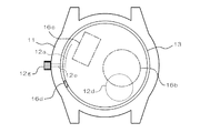
本実施形態の腕時計10は、時計ケース11と、この時計ケース11内に収容される時計機能体12と、時計ケース11の背後の開口を閉鎖する裏蓋13とを有している。また、時計ケース11の表面側にはガラス等よりなる表示窓14が取り付けられ、上記時計機能体12の表示部が視認可能な態様とされる。なお、本実施形態の腕時計10は、図5に示すように腕時計本体10Aと、時計バンド10Bとからなるが、以下の説明では腕時計本体10Aのみについて説明する。
The
時計機能体12には、ムーブメント等よりなる時計機構12aと、この時計機構12aの表面側に配置された文字板12bと、時計機構12aによって駆動される指針12cと、時計機構12aに電力を供給する電池、キャパシタ等よりなる時計電力源12dとが設けられる。文字板12bと指針12cは上記表示部を構成する。
The
ここで、上記時計ケース11が合成樹脂、セラミックスなどの絶縁材料で構成されることが後述する無線通信機能をより向上させることができる点で好ましい。ただし、金属材料等の導電性材料で時計ケース11を形成すれば、外観の自由度増大、質感の向上など見栄えの改善を図ることができる点で好ましい。また、文字板12b、指針12cなども合成樹脂、セラミックスなどといった絶縁材料で構成されることが望ましい。特に、文字板12bは裏蓋13を厚み方向に被覆する位置に配置されるので、絶縁材料で構成することで無線通信機能を高めることができる。
Here, it is preferable that the
時計ケース11の内部には上記時計機能体12を位置決め支持すると共に裏蓋13を内側から位置決め支持する位置決め枠12eが配置される。裏蓋13は時計ケース11に対して固定ねじ等の固定部材15で取り付け固定されている。裏蓋13の時計ケース11への取り付け方法としては、螺合、嵌め込みなどの種々の方法を用いることができる。ただし、上記の固定部材15による取付け方法(4本のネジによる固定)などのように、裏蓋13を時計ケース11に対して一定の姿勢で取り付けできる方法で固定することが、後述する通信アンテナと時計電力源12dとの間の平面的位置関係が保たれる点で望ましい。
A
時計機構12aには巻真12fが接続され、この巻真12fは時計ケース11を通して外部に突出する竜頭12gに接続されている。
A winding stem 12f is connected to the
裏蓋13は、時計ケース11の底部に対応する形状を外周部に備えた内側壁13aと、この内側壁13aの外周から厚み方向に設けられた周縁壁13bと、上記内側壁13aとは周縁壁13bを挟んで反対側に設けられた外側壁13cとを備えている。裏蓋13は少なくとも後述する通信アンテナ16bの性能を確保できる程度に、一部の壁面が絶縁材料で構成されるか、或いは、開口していることが好ましい。しかしながら、密閉性の確保や製造コストを考慮すると、特に、裏蓋13の全体が合成樹脂(プラスチック)等の絶縁材料で構成されていることが望ましい。
The
裏蓋13の内部には、無線通信機能を有する通信回路16aと、該通信回路16aに接続された通信アンテナ16bと、前記通信回路16aに電力を供給する通信電力源16cと、前記通信回路16aの通信機能を停止させる操作部材16dとを有する無線通信機能体16が収容されている。図示例の場合、裏蓋13は操作部材16dの外部操作部分を除いて無線通信機能体16が配置される収容部を閉鎖するように、上記内側壁13a、周縁壁13b及び外側壁13cが形成されている。なお、本発明の無線通信機能体16としては、無線通信機能のうち、受信機能のみを有するもの、或いは、送信機能のみを有するものであっても構わないが、本実施形態では受信機能と送信機能を共に有するものとして説明する。
Inside the
通信回路16aはたとえば基板と該基板に実装された電子部品とからなり、裏蓋13の収容部内において表側(時計機能体12側)に配置されている。図示例の場合、通信回路16aは裏蓋の内側壁13aの内面上に固定される。また、この通信回路16aに接続された通信アンテナ16bは、通信回路16aよりも裏側(時計機能体12とは反対側)に配置されている。図示例の場合、通信アンテナ16bは外側壁13cの内面上に固定されている。これによって通信アンテナ16bは時計ケース11及び時計機能体12から離間した位置に配置されるので、時計ケース11が金属で構成された場合などでも、通信アンテナ16bの機能低下を抑制できる。さらに、通信電力源16cもまた、通信回路16aよりも裏側に配置され、図示例では外側壁13cの内面上に配置されている。これは後述する交換用蓋による交換を容易にするための構成である。
The
図2に示すように、通信電力源16cに隣接する外側壁13cには開口部13dが形成され、該開口部13dは、通信電力源16cを出し入れ可能となるように構成されている。この開口部13dは交換用蓋13eによって開閉可能に構成されている。交換用蓋13eは外側壁13cの外面上に設けられる無線通信機能体16に供給される電力の補給を行うための上述の電力補給用構造である。
As shown in FIG. 2, an
交換用蓋13eは外側壁13cに対して螺合した状態で取り付けられている。交換用蓋13eの外面には工具係合溝などの工具やコイン等で開閉操作できる操作用構造が設けられ、当該操作用構造によって交換用蓋13eを回転させることで、外側壁13cより取り外したり外側壁13cに装着したりすることができるようになっている。
The
操作部材16dは、上記周縁壁13bに露出する外部操作部分を有し、たとえば、沈頭スイッチ、引き出し操作スイッチなどのように、不用意に操作されにくいスイッチ構造を有している。操作部材16dは、たとえば、航空機内、病院などといった電波の送受信が禁止されている場所において、使用者の意思で無線通信機能を停止させるためのものである。また、一旦停止した無線通信機能を開始(再開)させることも可能である。したがって、通常の使用時では操作する必要がないので、上述のように誤操作の防止に適したスイッチ構造とすることが好ましい。なお、無線通信機能体16が外部無線通信装置との間の相互認証のために間欠的に動作するように構成されている場合には、操作部材16dを操作して無線通信を無効化することで、通信電力源16cの無駄な消耗を防止することができる。
The
操作部材16dの外部操作部分は、図示例では4時方向の方位に設けられているが、一般には、3時半〜5時の範囲内、或いは、7時〜8時半の範囲内に設けることが好ましい。これらによれば、腕時計を時計バンドで腕に装着したままでも、容易に操作部材を操作することができる。特に、3時半〜5時の範囲内であれば袖先にも影響されずに容易に操作できる。なお、本明細書において、時刻で表された方位若しくは方位範囲については、通常の態様でアナログ腕時計を腕に装着した状態の時刻表示を基準にした方位を言い、したがって、アナログ時計以外の時計(ディジタル時計)でも、上記装着状態を基準としたときの上記方位に対応する方位を示すことになる。
The external operation portion of the
通信アンテナ16bは、たとえば誘電体アンテナなどの電子部品で構成でき、図示例では通信回路16aとは分離されて配置されている。ただし、通信回路16aの基板上に実装された電子部品で構成することもでき、また、基板上に形成された導体パターンの一部で構成することも可能である。後述するように13.56MHz〜2.4GHzの周波数帯で使用する場合、チップアンテナ、ループアンテナ、λ/4アンテナ、逆Fアンテナなどを好適に用いることができる。
The
通信アンテナ16bとしては、上述のいずれの態様で設置される場合であっても、厚みで0.5〜1.5mmの範囲内のものが好ましく、平面寸法で直径5〜15mmの範囲内の仮想円内に収まるものであることが望ましい。この範囲内であれば、通信アンテナ16bを腕時計として一般的な寸法のものの裏蓋内に容易に収容することができると共に、次に説明する所定の平面配置を容易に取ることができる。
The
通信アンテナ16bは、図3に示すように、通信電力源16c及び時計電力源12dとは平面的に重ならない位置に配置されている。一般に電池やキャパシタ等の電力源は導電体を主要構成とするものであって、腕時計の内部構造としては最も大きな導電体であるから、これらと平面的に重なる位置に配置された場合、通信アンテナ16bは大きな影響を受け、その受信性能若しくは送信性能を低下させる。通信アンテナ16bが通信電力源16c及び時計電力源12dと平面的に重ならないことで、特に厚み方向から入射した外来電波を効率的に受信でき、或いは、厚み方向へ電波を効率的に放射できる。この場合、時計電力源12dと通信電力源16とはなるべく広範囲において相互に(たとえば、一方が他方の全体と)平面的に重なるように配置されていることが好ましい。このようにすると、通信アンテナ16bの障害を与える平面領域をさらに低減することができ、通信アンテナ16bの平面配置の自由度を高めることができる。
As shown in FIG. 3, the
ここで、通信アンテナ16bは通信電力源16c及び時計電力源12dに対して平面的に最も離間した位置に配置されることが好ましい。図示例では、裏蓋13の中心位置を基準として通信電力源16c及び時計電力源12dが配置される方位と、通信アンテナ16bが配置される方位とが相互に反対方向となっている。また、通信アンテナ16bは時計機能体12の巻真12fが配置される3時方向に近い位置に配置される。通常、時計機能体12の巻真12fが配置される3時方向の近傍には時計電力源12dその他の大きな導電体を要する部品が配置されることはないので、当該巻真12fの影響をも回避するために巻真12fが配置される3時方向を基準として時計回り若しくは反時計回りに隣接した平面位置(たとえば、図示例のように1時半〜2時半方向を中心にした位置、或いは、3時半〜4時半方向を中心にした位置)に通信アンテナが配置されることがアンテナの機能を発揮する上で最も好ましい。
Here, it is preferable that the
図4は本実施形態の上記無線通信機能体16の概略構成を示す構成ブロック図である。通信回路16aは前述の基板上に実装されたICチップ等の電子部品や所定の配線パターン等で構成される。通信回路16aには、無線通信機能を制御する無線制御回路161が半導体IC等よりなるMPU(マイクロプロセッサユニット)又は論理回路等により構成され、この無線制御回路161の制御下にて以下に説明する各回路部が動作することで無線通信が行われる。
FIG. 4 is a configuration block diagram showing a schematic configuration of the wireless
上記通信アンテナ16bには復調回路162、キャリア検出回路164及び変調回路163が接続されている。上記復調回路162は、たとえば、通信アンテナ16bで受信された受信信号にASK復調を施し、受信データXを上記無線制御回路161に出力する。また、上記キャリア検出回路164は、上記受信信号にキャリアが含まれているか否かを検出し、キャリアが含まれている場合にはキャリア検出信号Yを上記無線制御回路161に出力する。さらに、上記変調回路163は、上記無線制御回路161から出力された送信データZにたとえばASK変調を行って送信制御信号を生成し、この送信制御信号に基づいて送信信号を生成して通信アンテナ16bに出力する。
A
記憶手段165は各種データを記録できるEPROM等の記録媒体で構成され、たとえば、無線通信機能体16の識別データIDなどを記憶する。これらの各種データは記憶手段165から上記無線制御回路161によって読み出され、上記無線通信に際して適宜に使用されるほか、上記無線通信で得られた種々のデータが上記無線制御回路161を介して適宜に記憶手段165に記録される。
The storage means 165 is composed of a recording medium such as EPROM capable of recording various data, and stores, for example, the identification data ID of the wireless
無線制御回路161には水晶振動子等よりなる基準振動子166と接続された基準信号生成回路167が接続されており、この基準信号生成回路167から出力される基準信号Sに基づいて、各種の動作が行われる。また、無線制御回路161は上記操作部材16dと接続され、操作部材16dの操作が行われると、無線通信機能を停止したり、或いは、無線通信機能を再開させたりすることができる。さらに、無線制御回路161に接続された報知部168は、たとえば、ブザー、点灯表示体、振動源などで構成され、無線通信機能に伴って使用者に注意を喚起する必要があるときに音、光、振動などでこれを知らせるようになっている。本実施形態では裏蓋13には点灯表示体や振動源(振動モータ)は設けられていないので、上記報知部168はブザー、スピーカなどの発音体で構成される。なお、以上説明した無線通信機能体16には通信電力源16cより電力が供給され、上記の各回路部が当該電力によって動作するようになっている。
The wireless control circuit 161 is connected to a reference
本実施形態では、無線通信機能体16と、時計機能体12との間には、信号のやりとりはもちろんのこと、電力供給経路をも含め、電気的な繋がりが一切存在しない。このため、裏蓋13には上記交換用蓋13eや操作部材16d以外に特別な構造は不要であり、電気端子なども不要である。したがって、時計ケース11及び裏蓋13の構造を簡易に構成でき、小型化、薄型化も容易になるとともに、製造コストも低減できる。また、無線通信機能体16の電池交換などを行っても、腕時計の時計ケース11自体の気密性には影響を与えないので、防水性の確保も容易である。
In the present embodiment, there is no electrical connection between the wireless
また、本実施形態では電力消費の多い無線通信機能体16の通信電力源16cを時計電力源12dとは別に設けると共に、無線通信機能体16の電力補給(通信電力源16c(電池)の交換)を裏蓋13を取り外さずに行うことができるようにしたので、電力補給を煩雑な作業なしに容易に、しかも、時計機能体12へ影響を与えずに、支障なく行うことができる。
In the present embodiment, the
本実施形態の無線通信機能の近距離無線通信方式としては、たとえば、特定小電力通信、微弱無線通信、Bluetooth、Zigbee、無線LAN(IEEE802.11)、RF−ID(ISO14443、ISO15693)などの通信規格に対応したものが挙げられる。これらの通信方式では、通常、13.56MHz〜2.4GHzの周波数帯を使用する。ただし、本発明は上記の規格に限定されるものではなく、たとえば、携帯電話の通信規格、電波時計の通信規格に対応したものであってもよい。 As the short-range wireless communication method of the wireless communication function of the present embodiment, for example, communication such as specific low power communication, weak wireless communication, Bluetooth, Zigbee, wireless LAN (IEEE802.11), RF-ID (ISO14443, ISO15693), etc. The thing corresponding to a standard is mentioned. In these communication systems, a frequency band of 13.56 MHz to 2.4 GHz is usually used. However, the present invention is not limited to the above-mentioned standards, and may be, for example, compatible with mobile phone communication standards and radio wave clock communication standards.
図5は本実施形態の動作態様を示す概略説明図である。本実施形態の腕時計10は、外部送受信装置100及び関連設備200と共に通信システムを構成する。外部送受信装置100は、制御部110、受信回路120、送信回路130及び高周波回路140を有し、上記腕時計100との間の無線通信によりデータの授受を行う。また、外部送受信装置100は、関連設備200との間で適宜のデータ交換を行い、使用者が関連設備200の処理等に関連したサービスを受けることができるように構成される。
FIG. 5 is a schematic explanatory view showing an operation mode of the present embodiment. The
上記サービスの例としては、たとえば、入退場ゲート装置に上記外部送受信装置100が組み込まれ、上記関連設備200として電子決済処理装置を接続してなる電子決済システム、上記外部送受信装置100が組み込まれた関連設備200としての携帯電話機又はパーソナルコンピュータと腕時計10の間で信号のやり取りを行い、当該携帯電話機又はパーソナルコンピュータが使用者から離間したときには自動的に機能ロックがかかったり、携帯電話機に着信があったときにはこれを報知したりする電子機器連携システム、外部送受信システム100が組み込まれた関連設備200として家屋、自動車、金庫等の電子施錠装置を有するセキュリティシステム或いはキーレスエントリーシステムなどが例示される。
As an example of the service, for example, the external transmission /
図6は上記の動作態様における本実施形態の動作手順の例を示す概略フローチャートである。まず、操作部材16dを操作することで無線通信機能を再開させると、無線制御回路161が各回路部に指令を出し、無線通信を行って外部送受信装置100との間で、外部送受信装置100に対して識別データ(ID)を送信するなどの相互認証処理を行う。相互認証が完了して無線通信モードが確立された場合には、無線制御回路161より制御信号を報知部168へ送出し、当該報知部168が所定のブザー音などを発音する等の報知パターンAで報知動作を行う。そして、この場合には、以後、当該無線通信モードにて腕時計10と外部送受信装置100との間で無線通信が行われ、所定の処理が実行される。
FIG. 6 is a schematic flowchart showing an example of the operation procedure of the present embodiment in the above operation mode. First, when the wireless communication function is resumed by operating the
一方、外部送受信装置100が近隣に存在しないなどの理由により相互認証ができなかった(認証動作に失敗した)場合には、上記とは別の報知パターンBにて報知が行われる。この場合には、再び上記の相互認証の試みが所定時間間隔で繰り返し行われる。たとえば、ポーリング方式であれば、定期的にポーリング信号を送り続け、外部送受信装置100の応答を待つ。なお、上記の説明とは逆に、信号を外部送受信装置100側から送出するようにしても構わない。
On the other hand, when mutual authentication cannot be performed because the external transmission /
[第2実施形態]
次に、図7を参照して本発明に係る第2実施形態の腕時計20について説明する。本実施形態では時計ケース21だけが上記第1実施形態とは異なるのみで、他の部分、すなわち、時計機能体22(時計機構22a、文字板22b、指針22c、時計電力源22d、位置決め枠22e、巻真22f、竜頭22g)、裏蓋23(内側壁23a、周縁壁23b、外側壁23c、開口部23d、交換用蓋23e)、表示窓24、固定手段25、無線通信機能体26(通信回路26a、通信アンテナ26b、通信電力源26c、操作部材26d)は第1実施形態と同一に構成できるので、これらの説明は省略する。
[Second Embodiment]
Next, a
本実施形態では、時計ケース21が合成樹脂(プラスチック)等の絶縁材料で構成されたケース基材21Aと、このケース基材21Aの外表面上に固定された外装材21Bとによって構成される。ここで、時計ケース21の強度、防水などのケースとしての本来的機能はケース基材21Aで確保されることが好ましい。図示例の場合、外装材21Bは金属等の板状材であり、ケース基材21Aの外表面を部分的に(特に表示窓24の周囲部などの表面側範囲において)被覆した状態で固定されている。これによって、時計ケース21の多くを絶縁材料で構成することで無線通信機能体26の通信性能を確保しつつ、外装材21Bによって腕時計としての外観を自由に設定でき、たとえば、質感を向上させたり、デザインのバリエーションを広げたりすることができる。
In the present embodiment, the
[第3実施形態]
次に、図8を参照して本発明に係る第3実施形態の腕時計30について説明する。本実施形態では時計機能体32だけが上記第1実施形態とは異なるのみで、他の部分、すなわち、時計ケース31、裏蓋33(内側壁33a、周縁壁33b、外側壁33c、開口部33d、交換用蓋33e)、表示窓34、固定手段35、無線通信機能体36(通信回路36a、通信アンテナ36b、通信電力源36c、操作部材36d)は第1実施形態と同一に構成できるので、これらの説明は省略する。
[Third Embodiment]
Next, a
本実施形態の時計機能体32は、先の各実施形態の時計機構の代わりに時計回路32a及び表示パネル32bを有し、時計回路32aには、回路基板32a−1と、この回路基板上に実装された時計IC32a−2及び水晶振動子32a−3などが設けられている。また、表示パネル32bはたとえば液晶表示体、有機ルミネッセンス表示体などで構成され、時計回路32a内に設けられた駆動回路により適宜の表示ができるように構成される。また、時計回路32aには時計電力源32dが接続されるとともに、図示しない操作スイッチなどが接続されている。
The
このように時計機能体32が異なる場合でも、上記第1実施形態で説明したように、本発明の構成は基本的に不変である。なお、時計回路32aを小型化することができるのであれば、時計回路32aを無線通信機能体36内の通信アンテナ36bと平面的に重ならない位置に限定して配置することが望ましく、さらに、時計ケース31を全て絶縁材料で構成することが望ましい。なお、先の実施形態でも述べたが、図示例のように通信アンテナ36bを通信回路36aを構成する基板上に実装してもよい。
Even when the
[第4実施形態]
次に、図9を参照して本発明に係る第4実施形態の腕時計40について説明する。本実施形態では時計機能体42だけが上記第1実施形態とは異なるのみで、他の部分、すなわち、時計ケース41、裏蓋43(内側壁43a、周縁壁43b、外側壁43c、開口部43d、交換用蓋43e)、表示窓44、固定手段45、無線通信機能体46(通信回路46a、通信アンテナ46b、通信電力源46c、操作部材46d)は第1実施形態と同一に構成できるので、これらの説明は省略する。
[Fourth Embodiment]
Next, a
本実施形態の時計機能体42は、基本的に第1実施形態と同様に構成された時計機構42a、文字板42b、指針42c、時計電力源42d、位置決め枠42e、巻真42f、竜頭42gを有するが、さらに、文字板42bの背後に重ねて配置された太陽電池パネル42hを備えている。この場合、文字板42bとしては透光性を有する素材、たとえば、合成樹脂(プラスチック)やセラミックス基板などを用いることが好ましい。これらは同時に絶縁材料でもあるため、無線通信機能体46にとっても好都合である。
The
太陽電池パネル42hは、表示窓44及び文字板42bを通過した外光を受けて発電を行い、当該発電によって生成された電力は大容量キャパシタ、化学二次電池等で構成される時計電力源42dに蓄電される。そして、時計機能体42は基本的には当該太陽電池パネル42hで発電された電力のみで駆動される。太陽電池パネル42hは、たとえば、プラスチックフィルム、ガラス等よりなる絶縁基板上に、アモルファスシリコン、多結晶シリコン、単結晶シリコンなどで構成された半導体薄膜と、当該半導体薄膜に接続された電極膜とを形成することで構成される。この太陽電池パネル42hは本発明の発電手段に相当する。
The
なお、上記第3実施形態の構成に本実施形態の発電手段を設けても構わない。また、発電手段としては上記の太陽電池に限らず、たとえば、回転錘と、該回転錘に接続されたロータを備えた小型発電機とを有するものであってもよい。 In addition, you may provide the electric power generation means of this embodiment in the structure of the said 3rd Embodiment. Further, the power generation means is not limited to the solar cell described above, and may include, for example, a rotating weight and a small generator including a rotor connected to the rotating weight.
本実施形態では、先の各実施形態と同様の効果を奏する他に、時計機能体42に対する電力補給の必要がなくなるため、使用者は裏蓋43の内部に収容された通信電力源46cのみを交換すればよいことから、使用者や時計店の店員などが時計電力源と通信電力源とを混同する虞もないという利点が得られる。また、太陽電池パネルに用いる透光性基板(文字板42bや太陽電池パネル基板など)は一般に絶縁材で構成され、電波透過性をも有しているので、無線通信機能を確保する上でも都合がよい。
In the present embodiment, in addition to the same effects as those of the previous embodiments, it is not necessary to supply power to the
[無線通信機能体の構成例]
次に、図10乃至図12を参照して、上記各実施形態に適用可能な無線通信機能体の構成例について説明する。図10乃至図12は無線通信機能体のうち通信回路及び通信アンテナの構成を模式的に示す概略斜視図である。
[Configuration example of wireless communication function body]
Next, a configuration example of a wireless communication function body applicable to each of the above embodiments will be described with reference to FIGS. 10 to 12 are schematic perspective views schematically showing the configuration of a communication circuit and a communication antenna in the wireless communication function body.
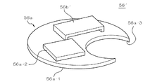
図10に示す構成例1では、無線通信機能体56内に設けられる通信回路56aとして、回路基板56a−1と、この回路基板56a−1上に実装された無線通信用IC56a−2とが設けられている。もっとも、回路基板56a−1には他の電子部品、たとえば、振動子、フィルタ、コンデンサ、抵抗、インダクタ等が実装されていてもよい。また、回路基板56上には通信アンテナ56bも実装されている。図示例の通信アンテナ56bは、たとえばセラミックなどの誘電体からなる表面実装形のチップアンテナである。
In the configuration example 1 shown in FIG. 10, a
回路基板56a−1には、化学1次電池、化学2次電池、キャパシタ等よりなる上記通信電力源を回避するための切り欠き部56a−3が設けられ、これによって、回路基板56a−1と通信電力源とを同じ厚み範囲に配置できるように構成される。したがって、無線通信機能体56を薄く形成することができるため、裏蓋の薄型化を図ることができる。通常、通信電力源は円盤型(たとえばボタン電池など)を有するので、上記回路基板56a−1の切り欠き部56a−3も円盤状の切り欠き形状を有するものとなっている。
The
図11に示す構成例2(無線通信機能体56′)では、通信アンテナ56b′のみが上記構成例1と異なるので、他の部分には同一符号を付し、それらの説明は省略する。この構成例では、通信アンテナ56b′が導電性に優れた材料、たとえば、銅、ステンレスなどの電気良導体で構成され、全体として板状に形成される。通信アンテナ56b′は回路基板56a−1上の回路パターンに接続されている。通信アンテナ56b′は回路基板56a−1上の回路パターンと協動して、ループアンテナ、逆Fアンテナを構成する。このような板状アンテナは数百MHz(100〜600MHz)域で有効であり、安価に構成できるという利点がある。
In the configuration example 2 (wireless
図12に示す構成例3(無線通信機能体56″)では、通信アンテナ56b″のみが上記構成例1及び2と異なるので、他の部分には同一符号を付し、それらの説明は省略する。この構成例では、通信アンテナ56b″が回路基板56a−1に形成された配線パターンで構成されたパターンアンテナとなっている。そして、当該通信アンテナ56b″は、図示例の場合、対応波長λに対してλ/4の長さで折り返されたパターンを有するメアンダアンテナ(折り返し形状アンテナ)となっている。また、パターンアンテナとしてループアンテナを構成してもよい。この種のアンテナは安価に構成でき、しかも、回路基板56a−1と一体化されているので、薄型かつコンパクトに構成可能で、無線通信機能体56の薄型化が容易になるという利点がある。
In the configuration example 3 (wireless
尚、本発明の腕時計は、上述の図示例にのみ限定されるものではなく、本発明の要旨を逸脱しない範囲内において種々変更を加え得ることは勿論である。 Note that the wristwatch of the present invention is not limited to the illustrated examples described above, and it is needless to say that various modifications can be made without departing from the scope of the present invention.
10…腕時計、11…時計機構、12…時計機能体、12a…時計機構、12b…文字板、12c…指針、12d…時計電力源、12e…位置決め枠、12f…巻真、12g…竜頭、13…裏蓋、13a…内側壁、13b…周縁壁、13c…外側壁、13d…開口部、13e…交換用蓋、14…表示窓、15…固定手段、16…無線通信機能体、16a…通信回路、16b…通信アンテナ、16c…通信電力源、16d…操作部材
DESCRIPTION OF
Claims (12)
前記裏蓋の内部には、通信回路と、該通信回路に接続された通信アンテナと、前記通信回路に電力を供給する通信電力源と、前記通信回路の通信機能を停止及び開始させる操作部材とを有する無線通信機能体が収容され、
前記無線通信機能体が前記時計機能体と電気的に独立し、前記裏蓋の外面に前記通信回路若しくは前記通信電力源に供給される電力の補給を行うための電力補給用構造が設けられていることを特徴とする腕時計。 In a watch having a watch case, a watch function body housed in the watch case, and a back cover for closing an opening behind the watch case,
Inside the back cover, a communication circuit, a communication antenna connected to the communication circuit, a communication power source that supplies power to the communication circuit, and an operation member that stops and starts the communication function of the communication circuit; A wireless communication functional unit having
The wireless communication function body is electrically independent from the timepiece function body, and a power supply structure for supplying power supplied to the communication circuit or the communication power source is provided on the outer surface of the back cover. A wristwatch characterized by being.
前記裏蓋の内部には、通信回路と、該通信回路に接続された通信アンテナと、前記通信回路に電力を供給する通信電力源と、前記通信回路の通信機能を停止及び開始させる操作部材とを有する無線通信機能体が収容され、
前記裏蓋の外面に前記通信回路若しくは前記通信電力源に供給される電力の補給を行うための電力補給用構造が設けられていることを特徴とする腕時計。 A watch case, a watch function body housed in the watch case, a watch power source for supplying power to the watch function body, a power generation means for supplying generated power to the watch function body or the watch power source, and the watch In a watch having a back cover that closes the opening behind the case,
Inside the back cover, a communication circuit, a communication antenna connected to the communication circuit, a communication power source that supplies power to the communication circuit, and an operation member that stops and starts the communication function of the communication circuit; A wireless communication functional unit having
A wristwatch characterized in that a power supply structure for supplying power supplied to the communication circuit or the communication power source is provided on the outer surface of the back cover.
Priority Applications (1)
| Application Number | Priority Date | Filing Date | Title |
|---|---|---|---|
| JP2007080873A JP2008241396A (en) | 2007-03-27 | 2007-03-27 | Wrist watch |
Applications Claiming Priority (1)
| Application Number | Priority Date | Filing Date | Title |
|---|---|---|---|
| JP2007080873A JP2008241396A (en) | 2007-03-27 | 2007-03-27 | Wrist watch |
Publications (2)
| Publication Number | Publication Date |
|---|---|
| JP2008241396A true JP2008241396A (en) | 2008-10-09 |
| JP2008241396A5 JP2008241396A5 (en) | 2010-05-13 |
Family
ID=39912938
Family Applications (1)
| Application Number | Title | Priority Date | Filing Date |
|---|---|---|---|
| JP2007080873A Withdrawn JP2008241396A (en) | 2007-03-27 | 2007-03-27 | Wrist watch |
Country Status (1)
| Country | Link |
|---|---|
| JP (1) | JP2008241396A (en) |
Cited By (9)
| Publication number | Priority date | Publication date | Assignee | Title |
|---|---|---|---|---|
| JP2013057643A (en) * | 2011-09-09 | 2013-03-28 | Wako:Kk | Wrist watch with non-contact ic card mounted |
| JP2013061308A (en) * | 2011-09-15 | 2013-04-04 | Seiko Epson Corp | Wrist device |
| JP2014209126A (en) * | 2014-06-26 | 2014-11-06 | セイコーエプソン株式会社 | Electronic wrist watch |
| JP2014238335A (en) * | 2013-06-07 | 2014-12-18 | カシオ計算機株式会社 | Human body mounting type electronic equipment |
| JP2016138895A (en) * | 2009-09-01 | 2016-08-04 | セイコーエプソン株式会社 | Electronic timepiece |
| JP2016186490A (en) * | 2016-06-02 | 2016-10-27 | セイコーエプソン株式会社 | Electronic wrist watch |
| US9977406B2 (en) | 2009-09-01 | 2018-05-22 | Seiko Epson Corporation | Timepiece with internal antenna |
| JP2018084586A (en) * | 2018-01-12 | 2018-05-31 | セイコーエプソン株式会社 | Electronic wrist watch |
| JP2019132684A (en) * | 2018-01-31 | 2019-08-08 | シチズン時計株式会社 | Atomic clock |
Citations (7)
| Publication number | Priority date | Publication date | Assignee | Title |
|---|---|---|---|---|
| JPH10197662A (en) * | 1996-12-28 | 1998-07-31 | Casio Comput Co Ltd | Receiver device |
| JPH11183657A (en) * | 1997-12-17 | 1999-07-09 | Woody:Kk | Wrist watch with incoming call annunciating function |
| JP2002221582A (en) * | 2001-11-29 | 2002-08-09 | Seiko Epson Corp | Portable watch with electronic device |
| JP2004085232A (en) * | 2002-08-23 | 2004-03-18 | Citizen Watch Co Ltd | Electronic clock for communication |
| JP2004514119A (en) * | 2000-11-11 | 2004-05-13 | ユングハンス、ウーレン、ゲゼルシャフト、ミット、ベシュレンクテル、ハフツング | Housing for emergency call transmitter |
| JP2005538367A (en) * | 2002-09-10 | 2005-12-15 | ザ スウォッチ グループ マネージメント サービシス エージー | Watch having an electronic module for storing information on the back side of the case |
| JP2006047234A (en) * | 2004-08-09 | 2006-02-16 | Seiko Epson Corp | Timepiece with radio function |
-
2007
- 2007-03-27 JP JP2007080873A patent/JP2008241396A/en not_active Withdrawn
Patent Citations (7)
| Publication number | Priority date | Publication date | Assignee | Title |
|---|---|---|---|---|
| JPH10197662A (en) * | 1996-12-28 | 1998-07-31 | Casio Comput Co Ltd | Receiver device |
| JPH11183657A (en) * | 1997-12-17 | 1999-07-09 | Woody:Kk | Wrist watch with incoming call annunciating function |
| JP2004514119A (en) * | 2000-11-11 | 2004-05-13 | ユングハンス、ウーレン、ゲゼルシャフト、ミット、ベシュレンクテル、ハフツング | Housing for emergency call transmitter |
| JP2002221582A (en) * | 2001-11-29 | 2002-08-09 | Seiko Epson Corp | Portable watch with electronic device |
| JP2004085232A (en) * | 2002-08-23 | 2004-03-18 | Citizen Watch Co Ltd | Electronic clock for communication |
| JP2005538367A (en) * | 2002-09-10 | 2005-12-15 | ザ スウォッチ グループ マネージメント サービシス エージー | Watch having an electronic module for storing information on the back side of the case |
| JP2006047234A (en) * | 2004-08-09 | 2006-02-16 | Seiko Epson Corp | Timepiece with radio function |
Cited By (11)
| Publication number | Priority date | Publication date | Assignee | Title |
|---|---|---|---|---|
| JP2016138895A (en) * | 2009-09-01 | 2016-08-04 | セイコーエプソン株式会社 | Electronic timepiece |
| JP2018054634A (en) * | 2009-09-01 | 2018-04-05 | セイコーエプソン株式会社 | Electronic timepiece |
| US9977406B2 (en) | 2009-09-01 | 2018-05-22 | Seiko Epson Corporation | Timepiece with internal antenna |
| US10209679B2 (en) | 2009-09-01 | 2019-02-19 | Seiko Epson Corporation | Timepiece with internal antenna |
| JP2013057643A (en) * | 2011-09-09 | 2013-03-28 | Wako:Kk | Wrist watch with non-contact ic card mounted |
| JP2013061308A (en) * | 2011-09-15 | 2013-04-04 | Seiko Epson Corp | Wrist device |
| JP2014238335A (en) * | 2013-06-07 | 2014-12-18 | カシオ計算機株式会社 | Human body mounting type electronic equipment |
| JP2014209126A (en) * | 2014-06-26 | 2014-11-06 | セイコーエプソン株式会社 | Electronic wrist watch |
| JP2016186490A (en) * | 2016-06-02 | 2016-10-27 | セイコーエプソン株式会社 | Electronic wrist watch |
| JP2018084586A (en) * | 2018-01-12 | 2018-05-31 | セイコーエプソン株式会社 | Electronic wrist watch |
| JP2019132684A (en) * | 2018-01-31 | 2019-08-08 | シチズン時計株式会社 | Atomic clock |
Similar Documents
| Publication | Publication Date | Title |
|---|---|---|
| JP2008241396A (en) | Wrist watch | |
| JP4165398B2 (en) | Electronic timepiece having contactless data communication function and contactless data communication system | |
| EP2749969B1 (en) | Timeepiece with wireless communication function | |
| JP2003152582A (en) | Arm-worn electronic equipment with radio function | |
| US9130272B2 (en) | Electronic device that is worn on the wrist | |
| US20070109208A1 (en) | Antenna in a shielded enclosure | |
| JP2012118045A (en) | Electronic timepiece with built-in antenna | |
| US20150180525A1 (en) | Cover case and electronic system | |
| CN106959600A (en) | Intelligent wristwatch structure | |
| JPH09247006A (en) | Wrist portable receiver | |
| JP2005244852A (en) | Electronic appliance | |
| SE541969C2 (en) | Hybrid watch patch-antenna | |
| JP2003215271A (en) | Electronic watch | |
| CN111727529B (en) | Wireless communication device, sensor device, and wearable device | |
| US20220373979A1 (en) | Watch configured to perform contactless electronic transactions | |
| JP2015008513A (en) | Wrist-mounted electronic equipment | |
| JP2001102839A (en) | Miniaturized electronic equipment | |
| JP2005318329A (en) | Antenna mounting member and communication terminal | |
| WO2019159790A1 (en) | Wireless communication apparatus, sensor apparatus, and wearable device | |
| JP3695455B2 (en) | Electronic equipment with wireless function | |
| JP3254880B2 (en) | Wrist-mounted antenna device and wireless device equipped with this antenna device | |
| CA2925979A1 (en) | Electronic locks with low-cost and low-power consumption smart rfid tags | |
| JP2002277569A (en) | Wristwatch with radio communication function | |
| JP2003066169A (en) | Watch with noncontact data communication function | |
| JP5776444B2 (en) | Sensitivity adjusting device and wristwatch |
Legal Events
| Date | Code | Title | Description |
|---|---|---|---|
| A521 | Written amendment |
Effective date: 20100324 Free format text: JAPANESE INTERMEDIATE CODE: A523 |
|
| A621 | Written request for application examination |
Free format text: JAPANESE INTERMEDIATE CODE: A621 Effective date: 20100324 |
|
| A977 | Report on retrieval |
Free format text: JAPANESE INTERMEDIATE CODE: A971007 Effective date: 20111012 |
|
| A131 | Notification of reasons for refusal |
Free format text: JAPANESE INTERMEDIATE CODE: A131 Effective date: 20111018 |
|
| A761 | Written withdrawal of application |
Effective date: 20111206 Free format text: JAPANESE INTERMEDIATE CODE: A761 |