JP5776444B2 - Sensitivity adjusting device and wristwatch - Google Patents
Sensitivity adjusting device and wristwatch Download PDFInfo
- Publication number
- JP5776444B2 JP5776444B2 JP2011185764A JP2011185764A JP5776444B2 JP 5776444 B2 JP5776444 B2 JP 5776444B2 JP 2011185764 A JP2011185764 A JP 2011185764A JP 2011185764 A JP2011185764 A JP 2011185764A JP 5776444 B2 JP5776444 B2 JP 5776444B2
- Authority
- JP
- Japan
- Prior art keywords
- antenna
- rotating member
- wristwatch
- sensitivity
- radio wave
- Prior art date
- Legal status (The legal status is an assumption and is not a legal conclusion. Google has not performed a legal analysis and makes no representation as to the accuracy of the status listed.)
- Active
Links
Images


Description
本発明は、感度調整装置及びこれを適用した腕時計に関するものである。 The present invention relates to a sensitivity adjustment device and a wristwatch to which the sensitivity adjustment device is applied.
近年、無線通信機能を備える腕時計等の電子機器間において、無線方式によってデータのやり取りをしたり、情報の同期を取ったりする等、各種データの送受信(通信)を行う手法が浸透しつつある。
こうした無線通信によって送受信されるデータには個人情報も多く含まれる可能性がある。このため、個人のプライバシー等を保護するためにも、データの送受信は特定の電子機器から特定の電子機器に対して正確に行われる必要がある。
In recent years, techniques for transmitting and receiving (communication) various types of data such as exchanging data by wireless methods and synchronizing information between electronic devices such as wristwatches having a wireless communication function have been spreading.
Data transmitted and received by such wireless communication may include a lot of personal information. For this reason, in order to protect personal privacy and the like, data transmission / reception needs to be accurately performed from a specific electronic device to a specific electronic device.
しかし、身の回りに複数の電子機器がある場合、他の電子機器との干渉が起こって目的の電子機器との間で正確に無線通信を行うことができないおそれがある。特にBluetooth(登録商標)など波長の長い電波を取り扱う際には、障害物等に強く電波が遮断されにくいという性質があるために、他の電子機器との干渉を起こしやすい。 However, when there are a plurality of electronic devices around the user, there is a possibility that interference with other electronic devices may occur and wireless communication cannot be performed accurately with the target electronic device. In particular, when handling radio waves having a long wavelength such as Bluetooth (registered trademark), the radio waves are strong against obstacles and are not easily cut off, and thus easily interfere with other electronic devices.
従来、無線通信システムにおいて、他の電子機器との干渉を避けて、通信を行いたい電子機器同士を適切にペアリング(すなわち、初期の認識作業)する方法として、ペアリングしたい電子機器(電子デバイス)を互いに近傍となる位置に配置するとともに、一方の電子機器から、無線通信システムにおける標準の信号出力電力レベルよりも小さい電力レベルに制限された問い合わせ信号を送信し、他方の電子機器がこの問い合わせ信号を検出すると、これに対する応答信号を送信する。そして、当該電子機器が問い合わせ信号に応答する最初の電子機器であることに基づいて、双方の電子機器間で、ポイントツーポイント接続を開始するという手法が提案されている(例えば、特許文献1参照)。 2. Description of the Related Art Conventionally, in a wireless communication system, as a method for appropriately pairing (that is, initial recognition work) between electronic devices that want to communicate while avoiding interference with other electronic devices, electronic devices (electronic devices) that are desired to be paired ) Are placed close to each other, and one electronic device transmits an inquiry signal limited to a power level lower than the standard signal output power level in the wireless communication system, and the other electronic device transmits this inquiry. When a signal is detected, a response signal corresponding to the signal is transmitted. Then, based on the fact that the electronic device is the first electronic device that responds to the inquiry signal, a method of starting point-to-point connection between both electronic devices has been proposed (see, for example, Patent Document 1). ).
このような手法でペアリングを行った場合には、他の電子機器との干渉を避けて目的とする電子機器間でのみ通信を成立させ、適切にペアリングを行うことができる。 When pairing is performed by such a method, communication can be established only between the target electronic devices while avoiding interference with other electronic devices, and pairing can be performed appropriately.
しかしながら、電子機器間でデータの送受信を行う目的は様々であり、ペアリングを行う場合のように電子機器同士を接触させる程度に近接させて通信を行う場合の他、例えばユーザ自身が身に着けている携帯端末装置と腕時計等の電子機器との間で各種データの送受信を行う場合のように多少離れた位置にある電子機器間でデータの送受信を行う場合や、ユーザが手元から離してしまった電子機器の所在を捜索する場合のようにある程度離れた場所にあると想定される電子機器との間で送受信を行う必要がある場合もある。 However, there are various purposes for transmitting and receiving data between electronic devices. In addition to the case where communication is performed as close as the electronic devices are brought into contact with each other as in the case of pairing, for example, the user himself / herself wears it. When transmitting / receiving data between electronic devices located at a slightly distant position, such as when transmitting / receiving various data between a portable terminal device and an electronic device such as a wristwatch, or when the user moves away from the hand In some cases, it is necessary to perform transmission / reception with an electronic device that is assumed to be located some distance away, such as when searching for the location of the electronic device.
このため、電子機器間でデータの送受信する際の電波の送受信感度は、その目的・用途・状況等に応じて適宜切り替えられることが求められる。 For this reason, the transmission / reception sensitivity of radio waves when transmitting / receiving data between electronic devices is required to be switched as appropriate according to the purpose, application, situation, and the like.
この点、携帯電話やパーソナルコンピュータ(personal computer)等では、受信回路等、通信関連モジュールにおいて送受信感度の切り替えを行っている。
しかし、通信関連モジュールにおいて送受信感度の切り替えを行う場合、通信関連モジュールの制御構成が複雑化する等の問題がある。
In this regard, in mobile phones, personal computers, and the like, transmission / reception sensitivity is switched in a communication-related module such as a receiving circuit.
However, when the transmission / reception sensitivity is switched in the communication-related module, there is a problem that the control configuration of the communication-related module becomes complicated.
本発明は以上のような事情に鑑みてなされたものであり、簡易な機構により、用途に応じた感度となるようにアンテナの送受信感度を調整することのできる感度調整装置及びこれを適用した腕時計を提供することを目的とするものである。 The present invention has been made in view of the circumstances as described above, and a sensitivity adjustment device capable of adjusting the transmission / reception sensitivity of an antenna so that the sensitivity according to the application is achieved by a simple mechanism, and a wristwatch to which the sensitivity adjustment device is applied. Is intended to provide.
前記課題を解決するために、本発明に係る感度調整装置は、
蓋部材により開口部を閉塞されてなる外装ケース内に収納され外部の機器との間で無線信号を送受信可能なアンテナの電波送受信感度を調整する感度調整装置であって、
前記蓋部材は、
前記外装ケースの開口部に取り付けられた蓋本体と、
前記アンテナを覆う位置に配置されるとともに前記蓋本体に対して回転可能に取り付けられた回転部材と、
を備え、
この回転部材は、回転の周方向に沿って電波の透過を妨げる遮蔽部と電波を透過させる開放部とを備え、前記遮蔽部により遮蔽される前記アンテナの被遮蔽範囲を調整することを特徴としている。
In order to solve the above-described problem, a sensitivity adjustment device according to the present invention includes:
A sensitivity adjustment device that adjusts the radio wave transmission / reception sensitivity of an antenna that is housed in an exterior case whose opening is closed by a lid member and can transmit and receive radio signals to and from an external device,
The lid member is
A lid body attached to the opening of the exterior case;
A rotating member disposed at a position covering the antenna and rotatably attached to the lid body;
With
The rotary member includes a Turkey adjust the target shielding range of the antenna circumferential direction along a releasing portion for transmitting a radio wave and a shielding portion that prevents the transmission of radio waves, which are shielded by the front Symbol shielding portion of the rotating It is characterized by.
また、本発明に係る腕時計は、
請求項1から請求項4のいずれか一項に記載の感度調整装置と、
前記感度調整装置により電波送受信感度を調整されるアンテナと、
前記アンテナを保持するモジュールと、
前記アンテナ及び前記モジュールを収納する外装ケースと、
を備えていることを特徴としている。
Moreover, the wristwatch according to the present invention is
The sensitivity adjustment device according to any one of
An antenna whose radio wave transmission / reception sensitivity is adjusted by the sensitivity adjustment device;
A module for holding the antenna;
An outer case for housing the antenna and the module;
It is characterized by having.
本発明によれば、アンテナの電波送受信感度を通信モードに適した感度に調整する手法として蓋本体に取り付けられた回転部材を回転させて遮蔽部により覆われるアンテナの被遮蔽範囲を調整するという機械的な構成をとっているため、受信回路等、通信関連モジュールにおいて送受信感度の切り替えを行う場合と比較して、アンテナの電波送受信感度の調整にかかる電力消費量を抑えることができるという効果を奏する。 According to the present invention, as a technique for adjusting the radio wave transmission / reception sensitivity of an antenna to a sensitivity suitable for the communication mode, a machine that adjusts the shielded range of the antenna covered by the shielding portion by rotating a rotating member attached to the lid body. As a result, the power consumption required for adjusting the radio wave transmission / reception sensitivity of the antenna can be reduced compared to the case where the transmission / reception sensitivity is switched in a communication-related module such as a reception circuit. .
以下、図1から図9を参照しつつ、本発明に係る感度調整装置及びこれを備える腕時計の好適な実施形態について説明する。なお、以下では、本発明に係る感度調整装置を電波通信機器としての機能を備える腕時計に適用した場合について説明するが、感度調整装置を適用可能な実施形態はこれに限定されるものではない。 Hereinafter, with reference to FIGS. 1 to 9, a preferred embodiment of a sensitivity adjustment device according to the present invention and a wristwatch including the sensitivity adjustment device will be described. In the following, a case where the sensitivity adjustment device according to the present invention is applied to a wristwatch having a function as a radio communication device will be described. However, embodiments to which the sensitivity adjustment device can be applied are not limited thereto.
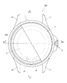
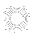
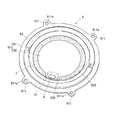
図1は、本実施形態に係る腕時計の一部を切り欠いた正面図であり、図2は、図1の腕時計を裏面側から見た図である。また、図3は、図1におけるIII−III線に沿う断面図であり、図4は、図3における一点鎖線部分の拡大図である。また、図5は、図1におけるV−V線に沿う断面図であり、図6は、図5における一点鎖線部分の拡大図である。
本実施形態に係る腕時計100は、電気的な駆動により図示しない指針(秒針、分針、時針)を回転させて時刻を表示するものである。なお、図1から図6では、指針等について図示を省略している。
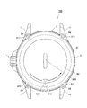
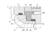
FIG. 1 is a front view in which a part of the wristwatch according to the present embodiment is cut away, and FIG. 2 is a view of the wristwatch of FIG. 3 is a cross-sectional view taken along line III-III in FIG. 1, and FIG. 4 is an enlarged view of an alternate long and short dash line portion in FIG. 5 is a cross-sectional view taken along the line V-V in FIG. 1, and FIG. 6 is an enlarged view of an alternate long and short dash line portion in FIG.
The
図1、図3等に示すように、腕時計100は、中空の短柱形状に形成された外装ケース1を備えている。本実施形態において外装ケース1は、例えばステンレス、チタニウム等の金属材料によって形成されている。なお、外装ケース1は、金属材料で形成されているものに限定されず、例えば樹脂等により形成されているものであってもよい。
As shown in FIGS. 1 and 3, the
この外装ケース1の上下両端部(図1において上下端部)、つまり時計の12時方向側端部及び6時方向側端部には、時計バンド(図示せず)が取り付けられるバンド取付部11が形成されている。
また、外装ケース1の側面には、外装ケース1の内部に貫通する貫通孔12(図3参照)が形成されている。なお、本実施形態では、貫通孔12は、腕時計100における3時方向の側面に形成されている場合を例としているが、貫通孔12が設けられる位置はこれに限定されない。例えば9時方向の位置や4時方向の位置に貫通孔12が設けられていてもよい。
A
Further, a through hole 12 (see FIG. 3) penetrating into the
図3に示すように、貫通孔12には、中空の筒状部材13が外装ケース1の外部から内部に挿通されている。そして、外装ケース1の側部であって貫通孔12の設けられている側には、筒状部材13を介して貫通孔12に挿入され、外装ケース1の外部から内部に挿通する軸部材21と、この軸部材21の一端側に形成され、筒状部材13の内径よりも大きな径を有する竜頭トップ22とを備える竜頭2が設けられている。
軸部材21の挿入側の端部には、図示しない歯車が設けられており、この歯車は、例えば後述するモジュール3内に設けられている図示しない分針等の各種指針を回動させる輪列の一部に接続されている。そして、竜頭2を回転させるとその回転力が指針を回動させる輪列に伝達され、指針の位置調整、時刻合わせ等が可能となるように構成されている。
As shown in FIG. 3, a hollow
A gear (not shown) is provided at the end of the
外装ケース1の内部には、ほぼ円柱形状に形成されたモジュール3が配置されている。なお、モジュール3の形状は円柱形状に限定されない。モジュール3は、腕時計100の指針(図示せず)を運針させる時計ムーブメント(例えば駆動用のモータや輪列機構等。図示せず)、各種電子部品を実装した回路基板(図示せず)等が例えば樹脂等によって形成されたハウジング(図示せず)に組み込まれたものである。
モジュール3は、腕時計100の裏面側(図3において下側)から中枠部材14によって支持されている。
Inside the
The
図5及び図6に示すように、本実施形態では、モジュール3の下側(腕時計100における裏面側)であって、モジュール3の周縁部における腕時計のほぼ6時方向にあたる位置(図1における下側位置)には凹部31が形成されており、この凹部31内にはチップ状又はループ状の小型のアンテナ4が配置されている。
アンテナ4は、例えば接着固定等によりモジュール3上に保持されている。なお、モジュール3に凹部31が形成されていることは必須ではなく、平坦な面に上にアンテナ4が配置されていてもよい。また、アンテナ4は、モジュール3の表面に貼着されていてもよいし、モジュール3内に埋設されていてもよい。また、アンテナ4の配置される位置はここに例示したものに限定されず、他の位置であってもよい。
As shown in FIGS. 5 and 6, in the present embodiment, the lower side of the module 3 (the back side of the wristwatch 100) and the position corresponding to the wristwatch approximately 6 o'clock in the peripheral portion of the module 3 (the lower side in FIG. 1). A
The
アンテナ4は、外部の機器との間で無線信号を送受信可能なものであり、例えばBluetooth(登録商標)等の規格により通信を行う。なお、アンテナ4の通信規格、通信可能な周波数帯は、Bluetooth(登録商標)に限定されず、腕時計100によって行われる各種通信に適したもの(すなわち、周波数等が適合するもの)が適宜適用される。また、アンテナ4は小型のものであればよく、種類、形状は特に限定されない。また、後述するように、本実施形態では、アンテナ4として、最大で5m程度の範囲内に存する機器との間で信号の送受信を行うことのできる電波送受信感度のものを適用しているが、アンテナ4の電波送受信感度はこれに限定されず、感度を最大としたときにさらに離れた機器との間で信号の送受信を行うことのできるものを用いてもよい。
このアンテナ4は、図示しないコネクタ等を介して回路基板と電気的に接続されており、このコネクタを介して、図示しない電波送受信制御回路と接続されている。
なお、本実施形態では、アンテナ4及び図示しない送受信制御回路自体は、常に最大の電波送受信感度(例えば本実施形態ではアンテナ4から5m程度の範囲内で電波を送受信可能な電波送受信感度)が維持されており、後述するように、感度調整装置10(図3参照)によるアンテナ4の被遮蔽範囲を変えることで電波送受信感度を機械的構成により調整するようになっている。
The
The
In this embodiment, the
外装ケース1内であって、モジュール3の上側(図3に置いて上側、すなわち腕時計100の視認側)には文字板5が配置されている。なお、モジュール3の上側にはアナログ方式の文字板5の他に数字や文字等をデジタル方式で表示する液晶表示部等が設けられていてもよい。
また、この文字板5の上、すなわちモジュール3の上方には、環状(リング状)に形成された見切り部材6が、その環状中心を中心として回転可能に設けられている。なお、見切り部材6は回転可能なものに限定されない。
A
A parting
外装ケース1は、表面側(図3及び図4において上側)の開口部と、裏面側(図3及び図4において下側)の開口部とを有している。そして、外装ケース1の表面側の開口部には、透明なガラス等の材料で形成された風防部材7が図示しない防水リング等を介して表面側の開口部を閉塞するように取り付けられている。
一方、外装ケース1の裏面側の開口部には、蓋部材としての裏蓋部材8が防水リング15を介して裏面側の開口部を閉塞するように取り付けられている。
The
On the other hand, a
ここで、図2から図8を参照しつつ、本実施形態の腕時計に設けられる裏蓋部材8について、詳細に説明する。
本実施形態において、裏蓋部材8は、裏蓋本体81、回転部材82、係止用リング部材83を備えている。
本実施形態では、これら裏蓋部材8を構成する部材のうち、裏蓋本体81及び係止用リング部材83は、例えばステンレス、チタニウム等の金属材料によって形成されており、回転部材82は、例えば工業用プラスチックやエンジニアプラスチック等の樹脂(例えばポリアセタール(POM)、ポリアミド(PA)、ポリカーボネート(PC)等)で形成されている。なお、裏蓋本体81、回転部材82及び係止用リング部材83を形成する材料はこれに限定されず、例えば裏蓋本体81や係止用リング部材83が例えば樹脂等の金属以外の材料により形成されていてもよいし、回転部材82がここに挙げた以外の材料により形成されていてもよい。
Here, the
In the present embodiment, the
In the present embodiment, among the members constituting the
図2、図3、図7等に示すように、裏蓋本体81は、ほぼ中央部が開口した環状(リング状)の部材であり、外装ケース1の開口部に取り付けられる蓋本体である。裏蓋本体81には、その外周に沿って4箇所に係止部811が設けられており、この係止部811にはねじ孔811aが形成されている。裏蓋部材8は、裏蓋本体81の係止部811をねじ84によって外装ケース1に固定することにより外装ケース1に取り付けられるようになっている。なお、裏蓋部材8を外装ケース1に取り付ける構成はここに例示したものに限定されない。
また、裏蓋本体81の内周面には、後述する係止用リング部材83のリング側ねじ溝832と螺合する本体側ねじ溝812が形成されている。
また、本実施形態では、裏蓋本体81の裏側の面(すなわち裏蓋部材8を外装ケース1に取り付けた際に外側となる面)であって、アンテナ4の設けられている位置に対応する位置(すなわち腕時計100の6時側)には、アンテナ4の位置を示すアンテナ指標813が付されている。なお、アンテナ指標813は、例えば、裏蓋本体81上に印刷、貼着、蒸着、彫刻等の手段により形成される。
As shown in FIG. 2, FIG. 3, FIG. 7, etc., the
Further, on the inner peripheral surface of the back cover
Further, in the present embodiment, it is a surface on the back side of the back cover body 81 (that is, a surface that is on the outside when the
裏蓋本体81には、開口部814を閉塞するように防水リング85を介してほぼ円盤状の回転部材82が回転可能に配置されている。
回転部材82は、裏蓋本体81の開口部814の内径とほぼ同じ外径を有するように形成されており、裏蓋本体81の表面側(図3において上側)から裏蓋本体81の開口部814に嵌め込むことにより裏蓋本体81の開口部814をほぼ隙間なく閉塞する。
また、回転部材82の表面側(すなわち裏蓋部材8を外装ケース1に取り付けた際に内側となる側)の外周には、裏蓋本体81の開口部814の内径よりも大きい外径を有する鍔部822が設けられており、回転部材82を裏蓋本体81の開口部814に嵌め込んだ際に、この鍔部822が裏蓋本体81の内側に係止されるようになっている。
回転部材82は、前述のように例えば樹脂等、電波を透過可能な材料により形成されており、その一部がモジュール3の上に保持されているアンテナ4の上を覆うように配置されている。なお、回転部材82を形成する材料は樹脂に限定されない。
A substantially disk-shaped rotating
The rotating
Further, the outer periphery on the surface side of the rotating member 82 (that is, the inner side when the
As described above, the rotating
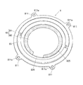
図7は、回転部材82を表面側(すなわち裏蓋部材8を外装ケース1に取り付けた際に内側となる側)から見た平面図である。
図7に示すように、回転部材82の表側の面には、回転部材82の回転の周方向に沿って磁性シート825が貼付(配置)されている。磁性シート825は、例えばフェライト等の磁性材料や磁性粉を含有する材料をシート状に加工した磁性体である。
本実施形態において、磁性シート825は、リング状に形成されたシートの一部が切り欠かれたほぼC字型となっている。
磁性シート825は、アンテナ4に入射しようとする電波を磁性材料の磁気損失により吸収して電波の透過を妨げるものであり、回転部材82のうち、磁性シート825が貼付(配置)されている部分は電波の透過を妨げる遮蔽部となり、磁性シート825が貼付(配置)されていない部分(すなわち、磁性シート825が切り欠かれている部分)は電波を透過させる開放部826となっている。
FIG. 7 is a plan view of the rotating
As shown in FIG. 7, a
In the present embodiment, the
The
また、図2に示すように、回転部材82の裏側の面(すなわち裏蓋部材8を外装ケース1に取り付けた際に外側となる面)であって、開放部826に対応する位置には、当該部分が電波を透過させる開放部826であることを示す感度指標827が付されている。感度指標827は、例えば、回転部材82上に印刷、貼着、蒸着、彫刻等の手段により形成される。なお、感度指標827が付される位置は開放部826に対応する位置に限定されず、例えば、開放部826と点対称となる位置(円盤状の回転部材82の中心点を対称点としたときの点対称位置)に対応する位置等であってもよい。
このように感度指標827を設けることにより、ユーザは感度指標827の位置を見ることによって、腕時計100の視認側から目視にて容易に遮蔽部(すなわち磁性シート825が貼付されている部分)及び開放部826の位置を確認することができる。
また、本実施形態では、上述のように、裏蓋本体81の裏側の面には、アンテナ4の位置を示すアンテナ指標813が付されており、感度指標827をこのアンテナ指標813に合わせることにより簡易に開放部826をアンテナ4の位置に合わせることができる。
Further, as shown in FIG. 2, the surface on the back side of the rotating member 82 (that is, the surface that becomes the outside when the
By providing the
In the present embodiment, as described above, the
また、図2及び図5に示すように、回転部材82の裏側の面(すなわち裏蓋部材8を外装ケース1に取り付けた際に外側となる面)のほぼ中央部には、細長く形成された溝状の凹部828が設けられている。凹部828は長手方向の中央部が最も深くなった断面ほぼ円弧状に形成されている。なお、凹部828の大きさ、深さ、形状等は人の爪先や硬貨等を差し込むことができる程度であればよく、特に限定されない。
回転部材82は、この凹部828に爪先や硬貨等を差し込んで図2におけるいずれかの矢印方向に回すことにより、回転部材82を時計回り又は反時計回りに任意の位置まで回転させることができるようになっている。そして、回転部材82を回転させることにより遮蔽部(すなわち磁性シート825が貼付されている部分)及び開放部826の位置を変更し、遮蔽部により遮蔽されるアンテナ4の被遮蔽範囲を調整することにより、アンテナ4の電波送受信感度を調整可能に構成されている。
Further, as shown in FIG. 2 and FIG. 5, the back surface of the rotating member 82 (that is, the surface that becomes the outside when the
The rotating
係止用リング部材83は、外周面にリング側ねじ溝832が形成された環状(リング状)の部材である。
係止用リング部材83の一端側には、係止用リング部材83の環状中心に向かってほぼ水平に張り出した張出部833が形成されている。なお、張出部833は、係止用リング部材83の全周に亘って設けられていてもよいし、係止用リング部材83の内周に沿って数箇所に部分的に設けられていてもよい。
係止用リング部材83は、裏蓋本体81に回転部材82を嵌め込んだ後に回転部材82の外周面と裏蓋本体81の内周面との間に装着することにより、回転部材82が裏蓋本体81から抜け落ちないように係止するものである。
具体的には、係止用リング部材83のリング側ねじ溝832と裏蓋本体81の本体側ねじ溝812とを螺合させることにより、係止用リング部材83の張出部833が回転部材82の鍔部822を上側(図3及び図4において上側)から係止するようになっている。これにより、回転部材82の鍔部822が防水リング85に押し付けられて裏蓋部材8の気密性が確保された状態となるとともに、回転部材82が裏蓋本体81に対して回転可能に取り付けられる。
The locking
On one end side of the
The locking
Specifically, the protruding
前述のように、回転部材82は、磁性シート825が貼付されている部分である遮蔽部と、磁性シート825が貼付されていない部分である開放部826とを備えており、ユーザの操作により回転部材82が外装ケース1の周方向に沿って回転すると、これにより遮蔽部及び開放部826の位置が変更され、遮蔽部により覆われるアンテナ4の被遮蔽範囲を調整することができるように構成されている。
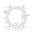
アンテナ4の被遮蔽範囲の調整について、図8及び図9を参照して説明する。図8及び図9は、モジュール3に固定されたアンテナ4及び回転部材82の配置を腕時計100の表面側(図3における上側)から見た図であり、モジュール3及びアンテナ4を二点鎖線で表している。
As described above, the rotating
Adjustment of the shielded range of the
ユーザの操作により、図8に示すように、遮蔽部(すなわち磁性シート825が貼付されている部分)がアンテナ4の配置されている位置(すなわち、腕時計100における6時方向の位置)の上方に来るように回転部材82を回転させると、アンテナ4の上方が磁性シート825によって覆われるため(すなわち、アンテナ4の被遮蔽範囲が広くなるため)、アンテナ4に入射しようとする電波が磁性シート825によって吸収され、アンテナ4の電波送受信感度は低くなる。
また、ユーザの操作により、図9に示すように、開放部826(すなわち磁性シート825が貼付されていない部分)がアンテナ4の配置されている位置(すなわち、腕時計100における6時方向の位置)の上方に来るように回転部材82を回転させると、アンテナ4の上方が磁性シート825によって覆われないため(すなわち、アンテナ4の被遮蔽範囲がなくなるため)、アンテナ4に入射しようとする電波がアンテナ4に入りやすくなり、アンテナ4の電波送受信感度は高くなる。
As shown in FIG. 8, by the user's operation, the shielding portion (that is, the portion to which the
In addition, as shown in FIG. 9, by the user's operation, the position where the
なお、本実施形態では、外装ケース1の開口部を閉塞する裏蓋部材8の裏蓋本体81と、この裏蓋本体81に対して回転可能に取り付けられた回転部材82とにより、アンテナ4の電波送受信感度を調整する感度調整装置10が構成されている。
In the present embodiment, the
この他、腕時計100は、例えば、各種モード切り替え等を行うための入力操作部、CPU(Central Processing Unit)、ROM(Read Only Memory)、RAM(Random Access Memory)、等から構成される制御部、電波の送受信を制御する送受信制御回路部、時刻補正等を行う計時回路部、発振回路部、指針を駆動させる指針駆動回路部等を備えている。これらは、一般的な腕時計に設けられているものと同様のものであるため、図示及び説明を省略する。
In addition, the
次に、本実施形態における感度調整装置10及び電波通信機器である腕時計100の作用について説明する。
Next, the operation of the
本実施形態において、腕時計100は、感度調整装置10によってアンテナ4の被遮蔽範囲を調整することにより、アンテナ4の電波送受信感度を調整できるようになっている。
すなわち、腕時計100は、異なる電波送受信感度の下で実現される複数の通信モード(本実施形態では後述する「ペアリングモード」「データ同期モード」「端末捜索モード/忘れ物防止モード」)を実現可能となっており、感度調整装置10は、これら各通信モードに適した電波送受信感度となるようにアンテナ4の被遮蔽範囲を調整する。
なお、通信モードの種類はこれに限定されない。「データ同期モード」「端末捜索モード/忘れ物防止モード」のうちいずれか1つのみを有するものであってもよいし、これら3つの通信モード以外の通信モードを実現可能となっていてもよい。
In the present embodiment, the
In other words, the
Note that the type of communication mode is not limited to this. Only one of “data synchronization mode” and “terminal search mode / thing left behind prevention mode” may be provided, or a communication mode other than these three communication modes may be realized.
このうち、ペアリングモードは、例えばユーザが腕時計100と新たな端末装置(例えば友人の端末装置等)との間で新たにペアリングを成立させ(すなわち、端末装置間において相互に関連付けを行う初期の登録作業を行い)、データの送受信等ができる状態にするための通信モードである。例えば腕時計100と新たな端末装置である友人の携帯電話との間でペアリングを行う場合には、腕時計100からペアリングしたい端末装置に対して問合せ信号を送信し、送信先の端末装置からこの問合せ信号に対する応答信号が腕時計100に送信され、腕時計100のアンテナ4がこの応答信号を受信して制御部に送ると、腕時計100と当該端末装置との間でペアリングが成立する。
Among these, in the pairing mode, for example, the user establishes a new pairing between the
ペアリングを行う際には、周囲に存する他の端末装置との間で予期せぬペアリングが成立することのないように、腕時計100と端末装置とが接触又はそれに近い距離まで接近した場合にのみ電波の送受信が可能な程度までアンテナ4の電波送受信感度が低くなるように調整することが好ましい。
このため、本実施形態では、入力操作部等からペアリングモードを選択する指示が入力されペアリングモードで通信を行う場合には、回転部材82の遮蔽部である磁性シート825が貼付されている部分がアンテナ4の上方に位置するように回転部材82を回転させ、アンテナ4の電波送受信感度が低くなるように調整する。
具体的には、ユーザが回転部材82の凹部828に爪部や硬貨等を差し仕込んで回転部材82を回転操作することにより、開放部826に対応して設けられている感度指標827が腕時計100の6時位置以外に配置される位置まで回転部材82を回転させ、遮蔽部(磁性シート825が貼付されている部分)がアンテナ4の上方を覆う位置にくるように調整する(図8参照)。
この状態で、ユーザがペアリングの対象となる端末装置を腕時計100に接触又は10cm程度の距離まで近接させると、腕時計100のアンテナ4からペアリングのための問合せ信号(例えば腕時計100の個体識別番号等を含む信号)が送信され、この問合せ信号を受信可能な距離にある端末装置のみが当該信号を受信する。問合せ信号を受信した端末装置は応答信号(例えば当該端末装置の個体識別番号等を含む信号)を腕時計100に返信し、腕時計100のアンテナ4がこの応答信号を受信すると、当該応答信号が制御部に送られ、制御部は当該端末装置を以後腕時計100との間でデータの送受信が可能な端末装置として登録する。これによりペアリング(端末装置間の初期登録作業)が完了する。
When performing pairing, the
For this reason, in this embodiment, when an instruction to select a pairing mode is input from the input operation unit or the like and communication is performed in the pairing mode, a
Specifically, when the user inserts a claw or a coin into the
In this state, when the user contacts the terminal device to be paired with the
なお、ペアリングが成立したか否かは、文字板5上での指針や液晶表示部等におけるその旨の表示、図示しないライトの点滅、アラーム音等によりユーザに報知されるようにすることが好ましい。
また、アンテナ4の電波送受信感度の低い状態(すなわち、磁性シート825がアンテナ4の上方を覆っている状態)では目的の端末装置との間で適切にペアリングを成立させることができなかった場合(すなわち、ペアリングが成立していない旨の表示等がされた場合)には、ユーザが回転部材82の凹部828に爪部や硬貨等を差し仕込んで回転部材82を回転操作することにより、感度指標827が腕時計100の6時位置に配置される位置まで回転部材82を回転させ、開放部826(磁性シート825が貼付されていない部分)がアンテナ4の上方を覆う位置にくるように調整した上で、再度ペアリングを試みるようにしてもよい。
Whether or not pairing has been established may be notified to the user by a pointer on the
In addition, when the
これに対して、データ同期モードは、例えば既に腕時計100との間でペアリングが成立している端末装置であって、ユーザが身につけている端末装置等(例えば、ユーザの所持している図示しない携帯電話)、腕時計100の比較的近距離(例えばアンテナ4からの距離が1〜2m程度の範囲内)に位置する端末装置との間でデータの同期を図ることを想定した通信モードである。
また、端末捜索モードは、例えばユーザが腕時計100との間でペアリング済みである自己又は友人の端末装置等の場所を捜索する場合を想定した通信モードであり、忘れ物防止モードは、例えばユーザが腕時計100との間でペアリング済みである自分の端末装置から所定の距離(例えば5m程度)以上離れたときに、ブザー等により警告を発することを想定した通信モードである。
On the other hand, the data synchronization mode is, for example, a terminal device that has already been paired with the
In addition, the terminal search mode is a communication mode that assumes a case where the user searches for a place such as a terminal device of a self or a friend who has been paired with the
これらはいずれも、既に腕時計100との間でペアリングが成立している端末装置との間で行われる通信であるため、予期しない端末装置との間で通信が成立するおそれはない。
このため、本実施形態では、入力操作部等から「データ同期モード」又は「端末捜索モード/忘れ物防止モード」を選択する指示が入力されこれらの通信モードで通信を行う場合には、回転部材82の開放部826である磁性シート825が貼付されていない部分がアンテナ4の上方に位置するように回転部材82を回転させ、アンテナ4の電波送受信感度が高くなるように調整する。
具体的には、ユーザが回転部材82の凹部828に爪部や硬貨等を差し仕込んで回転部材82を回転操作することにより、開放部826に対応して設けられている感度指標827が腕時計100の6時位置に配置される位置まで回転部材82を回転させ、開放部826(磁性シート825が貼付されていない部分)がアンテナ4の上方位置にくるように調整する(図9参照)。
これにより、腕時計100は、アンテナ4が多少離れた距離にある端末装置との間で電波を送受信することのできる状態となり、例えばユーザが身に付けている携帯電話等との間でデータの送受信を行うことにより、相互のデータを同期させることができる。また、例えば端末捜索モードであれば、腕時計100から5m程度の範囲内に存するペアリング済みの端末装置に対して、腕時計100のアンテナ4から応答を要求する信号が送信され、端末装置がこの信号を受信して応答信号を腕時計100に送信すると、その旨がブザー等の音やライトの点滅等によりユーザに報知される。また、例えば忘れ物防止モードであれば、腕時計100のアンテナ4からペアリング済みの端末装置に対して応答を要求する信号が送信され、端末装置はこの信号を受信して応答信号を腕時計100に送信する。そして、端末装置からの応答信号が受信できなくなると、腕時計100の制御部は端末装置が所定の距離(本実施形態ではアンテナ4の電波送受信可能な範囲である5m)以上ユーザから離間したと判断して、その旨をブザー等の音やライトの点滅等によりユーザに報知する。
Since these are communications performed with a terminal device that has already been paired with the
For this reason, in this embodiment, when an instruction to select “data synchronization mode” or “terminal search mode / thing left behind prevention mode” is input from the input operation unit or the like and communication is performed in these communication modes, the rotating
Specifically, when the user inserts a claw or a coin into the
As a result, the
以上のように、本実施形態によれば、異なる電波送受信感度の下で実現される複数の通信モード(例えばペアリングモード、データ同期モード、端末捜索モード/忘れ物防止モード)を実現可能であるため、ユーザの目的・用途に応じた各種の通信を行うことができる。
そして、アンテナ4の電波送受信感度をこれらの通信モードに適した感度に調整する手法として回転部材82を回転させて遮蔽部により覆われるアンテナ4の被遮蔽範囲を調整するという機械的な構成をとっているため、受信回路等、通信関連モジュールにおいて電波送受信感度の切り替えを行う場合と比較して、アンテナ4の電波送受信感度の調整にかかる電力消費量を抑えることができる。
また、腕時計100の場合、小型・軽量化が求められ、大型のバッテリを収容するスペースを確保することが難しいが、本実施形態における腕時計100は、外装ケース1の開口部に装着される裏蓋本体81と、アンテナ4を覆う位置に配置された回転部材82とにより構成される感度調整装置10を備えており、機械的な構成によりアンテナ4の電波送受信感度を調整することができる。このため、通信関連モジュールにおいて電波送受信感度の切り替えを行う場合と比較して電力消費量を抑えることができ、大型のバッテリ等を備える必要がないため、装置の小型・軽量化を図ることができる。
また、外装ケース1の開口部を閉塞する裏蓋部材8を構成する回転部材82に遮蔽部と開放部826とを設けて、この回転部材82を回転させることによりアンテナ4の電波送受信感度を調整することができるため、新たに電波送受信感度を調整するための部材を設けることなく通信モードに適した感度の調整を行うことが可能であり、装置構成の簡易化、小型・軽量化を実現することができる。
また、遮蔽部は、回転部材82の裏面側に磁性体である磁性シート825を貼付することにより構成されているため、製造等が容易であり、生産コストを低く抑えることが可能である。
As described above, according to the present embodiment, it is possible to realize a plurality of communication modes (for example, the pairing mode, the data synchronization mode, the terminal search mode / the lost item prevention mode) realized under different radio wave transmission / reception sensitivities. Various communications according to the user's purpose and application can be performed.
Then, as a method for adjusting the radio wave transmission / reception sensitivity of the
Further, in the case of the
Further, the rotating
In addition, since the shielding portion is configured by sticking a
なお、以上本発明の実施形態について説明したが、本発明は、かかる実施形態に限定されず、その要旨を逸脱しない範囲で、種々変形が可能であることは言うまでもない。 Although the embodiments of the present invention have been described above, the present invention is not limited to such embodiments, and various modifications can be made without departing from the scope of the present invention.
例えば、上記実施形態では、磁性体である磁性シート825がほぼC字型に配置される場合を例としたが、磁性シート825の形状や配置はこれに限定されない。
例えば、図10に示すように、感度調整装置20を構成する回転部材92の裏面側の一部分のみに、アンテナ4を被覆することのできる大きさの磁性シート925を貼付してもよい。この場合には、磁性シート925が貼付されている部分が遮蔽部となり、それ以外の部分が開放部926となる。
したがって、ペアリングを行う際(すなわち「ペアリングモード」のとき)には、図11に示すように、磁性シート925が貼付されている部分がアンテナ4を被覆する位置まで回転部材92を回転させる。これによりアンテナ4の電波送受信感度をペアリングに適した感度まで低下させることができる。そして、図11に示す状態において端末装置間のペアリングが成立しなかったとき、又はペアリングが成立している端末装置同士でデータを同期させたり(すなわち「データ同期モード」のとき)、ペアリングが成立している端末の捜索等を行う場合(すなわち「端末捜索モード/忘れ物防止モード」のとき)には、図12に示すように、開放部926(すなわち磁性シート925が貼付されていない部分)がアンテナ4の上に位置するように回転部材92を回転させる。これにより離れた場所にある端末装置間でも電波の送受信が可能な程度までアンテナ4の電波送受信感度を高くすることができる。
For example, in the above-described embodiment, the case where the
For example, as shown in FIG. 10, a
Therefore, when performing pairing (that is, in the “pairing mode”), as shown in FIG. 11, the rotating
また、本実施形態では、磁性体が回転部材82に貼付された磁性シート825である場合について説明したが、磁性体はシート状のものでなくてもよい。
また、磁性体は回転部材82のアンテナ4と対向する面に配置されていればよく、磁性体を配置する手法は貼付に限定されない。例えば、回転部材82の一部に磁性体を埋め込むことにより遮蔽部を形成してもよいし、磁性材料や磁性粉を含有する材料を蒸着、印刷する等の手法により回転部材82に磁性体を配置して遮蔽部を形成してもよい。
In this embodiment, the case where the magnetic body is the
Moreover, the magnetic body should just be arrange | positioned in the surface facing the
また、本実施形態では、回転部材82において、磁性体である磁性シート825が貼付(配置)されている部分が遮蔽部となり、磁性シート825が貼付(配置)されていない部分が開放部826となる場合について説明したが、遮蔽部及び開放部の構成はこれに限定されない。
例えば、回転部材自体を電波の透過を妨げる電波遮蔽材料で形成し、この回転部材の一部を他の部分よりも厚く形成された肉厚部として、他の部分よりも電波が透過しにくいように構成してもよい。電波遮蔽材料とは、例えば電波を吸収する電波吸収体等、電波の透過を妨げることのできる材料であり、具体的には、例えば、磁性材料や磁性粉を含有する材料を所定の形状に成型したり、所定の形状に成型された基材に磁性シートを貼付することにより形成する。この場合には、肉厚部が遮蔽部となり、それ以外の部分が開放部となる。なお、肉厚部の位置を示すために、回転部材の裏側の面(すなわち裏蓋部材を外装ケースに取り付けた際に外側となる面)であって、肉厚部に対応する位置に、当該部分が遮蔽部であることを示す感度指標が付されることが好ましい。
このように肉厚部が遮蔽部となり、それ以外の部分が開放部となる場合にも、機械的な構成によりアンテナ4の電波送受信感度を調整することができ、感度調整のために大型のバッテリ等を備える必要がないため、装置の小型・軽量化を図ることができる。
Further, in the present embodiment, in the rotating
For example, the rotating member itself is made of a radio wave shielding material that prevents transmission of radio waves, and a part of this rotating member is made thicker than other parts so that radio waves are less likely to pass through other parts. You may comprise. A radio wave shielding material is a material that can prevent the transmission of radio waves, such as a radio wave absorber that absorbs radio waves. Specifically, for example, a magnetic material or a material containing magnetic powder is molded into a predetermined shape. Or by sticking a magnetic sheet to a base material molded into a predetermined shape. In this case, the thick part becomes the shielding part, and the other part becomes the open part. In addition, in order to show the position of the thick portion, the surface on the back side of the rotating member (that is, the surface that becomes the outside when the back cover member is attached to the exterior case), the position corresponding to the thick portion It is preferable that a sensitivity index indicating that the portion is a shielding portion is attached.
As described above, even when the thick portion becomes the shielding portion and the other portion becomes the open portion, the radio wave transmission / reception sensitivity of the
また、本実施形態では、遮蔽部に磁性体を配置して、磁性材料の磁気損失により電波を吸収することによって電波の透過を妨げる場合について説明したが、遮蔽部は電波の透過を妨げることができるものであればよく、その構成は磁気損失により電波を吸収するものに限定されない。 Further, in the present embodiment, a case has been described in which a magnetic body is disposed in the shielding part and the transmission of the radio wave is prevented by absorbing the radio wave due to the magnetic loss of the magnetic material. Any configuration can be used, and the configuration is not limited to a configuration that absorbs radio waves due to magnetic loss.
また、回転部材は、アンテナ4を覆うことが可能な位置に配置され、回転させることによって遮蔽部及び開放部の位置を変更し、遮蔽部により遮蔽されるアンテナ4の被遮蔽範囲を調整することができるものであればよく、その形状や大きさ等はここに例示したものに限定されない。例えば、本実施形態で例示したものよりも径の小さな回転部材を設ける構成としてもよい。また、回転部材は、裏蓋部材8のほぼ中央部に配置されているものに限定されず、アンテナ4に対応する位置に偏って配置されていてもよい。
The rotating member is disposed at a position where the
また、本実施形態では、裏蓋部材8が、裏蓋本体81、回転部材82、係止用リング部材83を備え、回転部材82が、係止用リング部材83によって裏蓋本体81に係止されている場合を例として説明したが、回転部材82を裏蓋本体81に係止する構成はこれに限定されない。
In this embodiment, the
また、本実施形態では、回転部材82に凹部828を設けて、この凹部828に爪部や硬貨等を差し込んで回転部材82を回転させる場合を例として説明したが、回転部材82を回転させる構成はこれに限定されない。例えば、回転部材82に凸部を設け、ユーザが凸部に指を掛けて回転部材82を回転させる構成としてもよい。
Further, in the present embodiment, a case has been described in which the rotating
また、本実施形態では、「ペアリングモード」で通信を行う際にはアンテナ4の上に遮蔽部を位置させ、「データ同期モード」又は「端末捜索モード/忘れ物防止モード」で通信を行う際にはアンテナ4の上に開放部を位置させるというように、アンテナ4の電波送受信感度について2段階の調整を行う場合を例として説明したが、アンテナ4の電波送受信感度の調整は2段階に限定されない。
例えば、遮蔽部とアンテナ4との位置関係を段階的に調整することにより、アンテナ4全体が遮蔽される状態、アンテナ4が一部遮蔽される状態、アンテナ4全体が遮蔽されない状態のように、複数段階の調整ができるようにしてもよい。この場合には、ユーザは、「ペアリングモード」で通信を行う際に、アンテナ4全体が遮蔽される状態ではペアリングが成立しなかった場合に、ペアリングが成立するまでアンテナ4の電波送受信感度を段階的に上げていくことができる。
In the present embodiment, when performing communication in the “pairing mode”, the shielding unit is positioned on the
For example, by adjusting the positional relationship between the shielding unit and the
また、本実施形態においては、腕時計100が指針を備えるアナログ式の腕時計である場合について説明したが、腕時計は、アナログ式に限定されない。例えば、液晶パネル等で構成された液晶表示部を備えるデジタル式の腕時計でもよいし、指針及び液晶表示部の双方を備える腕時計であってもよい。
In the present embodiment, the case where the
また、本実施形態においては、腕時計100の外装ケース1がほぼ円形であり、裏蓋本体81が環状(リング状)である場合を例として説明したが、腕時計100の外装ケース1の形状は特に限定されず、例えば四角形、楕円形等でもよい。この場合にも、回転部材は回転可能な形状(例えば円盤状)とするが、裏蓋本体及び裏蓋部材全体の形状は外装ケース1の形状に応じた形状(例えば四角形、楕円形等)とする。
Further, in the present embodiment, the case where the
また、上記実施形態では、感度調整装置10が腕時計に適用される場合を例として示したが、感度調整装置10を適用可能な機器は腕時計に限られず、蓋部材によって開口部を閉塞される外装ケースを有する機器であれば本発明を適用可能である。例えば、携帯電話やPDA等の各種携帯端末装置、携帯型の音楽再生装置、小型ラジオ等に本発明を適用してもよい。
Moreover, in the said embodiment, although the case where the
その他、本発明が本実施形態に限定されず、適宜変更可能であることはいうまでもない。 In addition, it cannot be overemphasized that this invention is not limited to this embodiment, and can be changed suitably.
以上本発明のいくつかの実施形態を説明したが、本発明の範囲は、上述の実施の形態に限定するものではなく、特許請求の範囲に記載された発明の範囲とその均等の範囲を含む。
以下に、この出願の願書に最初に添付した特許請求の範囲に記載した発明を付記する。付記に記載した請求項の項番は、この出願の願書に最初に添付した特許請求の範囲の通りである。
〔付記〕
<請求項1>
蓋部材により開口部を閉塞されてなる外装ケース内に収納され外部の機器との間で無線信号を送受信可能なアンテナの電波送受信感度を調整する感度調整装置であって、
前記蓋部材は、
前記外装ケースの開口部に取り付けられた蓋本体と、
前記アンテナを覆う位置に配置されるとともに前記蓋本体に対して回転可能に取り付けられた回転部材と、
を備え、
この回転部材は、回転の周方向に沿って電波の透過を妨げる遮蔽部と電波を透過させる開放部とを備え、前記回転部材を回転させることにより前記遮蔽部及び前記開放部の位置を変更し、前記遮蔽部により遮蔽される前記アンテナの被遮蔽範囲を調整することにより、前記アンテナの電波送受信感度を調整可能に構成されていることを特徴とする感度調整装置。
<請求項2>
前記遮蔽部は、前記回転部材の前記アンテナと対向する面に磁性体を設けることにより構成されていることを特徴とする請求項1に記載の感度調整装置。
<請求項3>
前記回転部材は、その回転の周方向の一部に他の部分よりも厚く形成された肉厚部を有し、
この肉厚部により前記遮蔽部が構成されていることを特徴とする請求項1に記載の感度調整装置。
<請求項4>
請求項1から請求項3のいずれか一項に記載の感度調整装置と、
前記感度調整装置により電波送受信感度を調整されるアンテナと、
前記アンテナを保持するモジュールと、
前記アンテナ及び前記モジュールを収納する外装ケースと、
を備えていることを特徴とする腕時計。
Although several embodiments of the present invention have been described above, the scope of the present invention is not limited to the above-described embodiments, but includes the scope of the invention described in the claims and equivalents thereof. .
The invention described in the scope of claims attached to the application of this application will be added below. The item numbers of the claims described in the appendix are as set forth in the claims attached to the application of this application.
[Appendix]
<Claim 1>
A sensitivity adjustment device that adjusts the radio wave transmission / reception sensitivity of an antenna that is housed in an exterior case whose opening is closed by a lid member and can transmit and receive radio signals to and from an external device,
The lid member is
A lid body attached to the opening of the exterior case;
A rotating member disposed at a position covering the antenna and rotatably attached to the lid body;
With
The rotating member includes a shielding portion that prevents transmission of radio waves along a circumferential direction of rotation and an opening portion that transmits radio waves, and changes the positions of the shielding portion and the opening portion by rotating the rotating member. The sensitivity adjustment device is configured to be capable of adjusting the radio wave transmission / reception sensitivity of the antenna by adjusting a shielded range of the antenna shielded by the shielding unit.
<Claim 2>
The sensitivity adjusting apparatus according to
<Claim 3>
The rotating member has a thick part formed thicker than the other part in a part of the circumferential direction of the rotation,
The sensitivity adjusting apparatus according to
<Claim 4>
The sensitivity adjustment device according to any one of
An antenna whose radio wave transmission / reception sensitivity is adjusted by the sensitivity adjustment device;
A module for holding the antenna;
An outer case for housing the antenna and the module;
A wristwatch characterized by comprising:
1 外装ケース
2 竜頭
3 モジュール
4 アンテナ
5 文字板
8 裏蓋部材
10 感度調整装置
81 裏蓋本体
82 回転部材
83 係止用リング部材
100 腕時計
813 アンテナ指標
825 磁性シート
826 開放部
827 感度指標
DESCRIPTION OF
Claims (6)
前記蓋部材は、
前記外装ケースの開口部に取り付けられた蓋本体と、
前記アンテナを覆う位置に配置されるとともに前記蓋本体に対して回転可能に取り付けられた回転部材と、
を備え、
この回転部材は、回転の周方向に沿って電波の透過を妨げる遮蔽部と電波を透過させる開放部とを備え、前記遮蔽部により遮蔽される前記アンテナの被遮蔽範囲を調整することを特徴とする感度調整装置。 A sensitivity adjustment device that adjusts the radio wave transmission / reception sensitivity of an antenna that is housed in an exterior case whose opening is closed by a lid member and can transmit and receive radio signals to and from an external device,
The lid member is
A lid body attached to the opening of the exterior case;
A rotating member disposed at a position covering the antenna and rotatably attached to the lid body;
With
The rotating member includes a shielding portion that prevents transmission of radio waves along the circumferential direction of rotation and an open portion that transmits radio waves, and adjusts a shielded range of the antenna shielded by the shielding portion. Sensitivity adjustment device.
前記電波送受信感度は、前記回転部材の回転によって前記アンテナが前記遮蔽部に覆われた場合に、低くなることを特徴とする請求項1に記載の感度調整装置。 The shielding portion is formed with a size covering the antenna,
The sensitivity adjustment apparatus according to claim 1, wherein the radio wave transmission / reception sensitivity is lowered when the antenna is covered by the shielding portion by rotation of the rotating member .
この肉厚部により前記遮蔽部が構成されていることを特徴とする請求項1又は請求項2に記載の感度調整装置。 The rotating member has a thick part formed thicker than the other part in a part of the circumferential direction of the rotation,
The sensitivity adjusting apparatus according to claim 1, wherein the shielding portion is configured by the thick portion.
前記感度調整装置により電波送受信感度を調整されるアンテナと、
前記アンテナを保持するモジュールと、
前記アンテナ及び前記モジュールを収納する外装ケースと、
を備えていることを特徴とする腕時計。 The sensitivity adjustment device according to any one of claims 1 to 4,
An antenna whose radio wave transmission / reception sensitivity is adjusted by the sensitivity adjustment device;
A module for holding the antenna;
An outer case for housing the antenna and the module;
A wristwatch characterized by comprising:
前記外装ケースの開口部に取り付けられた蓋本体と、 A lid body attached to the opening of the exterior case;
前記蓋本体に対して回転可能に取り付けられた回転部材と、 A rotating member rotatably attached to the lid body;
を備え、With
この回転部材は、回転の周方向に沿って電波の透過を妨げる遮蔽部と電波を透過させる開放部とを備えることを特徴とする感度調整装置。 The rotating member includes a shielding unit that prevents transmission of radio waves along a circumferential direction of rotation and an open unit that transmits radio waves.
Priority Applications (3)
| Application Number | Priority Date | Filing Date | Title |
|---|---|---|---|
| JP2011185764A JP5776444B2 (en) | 2011-08-29 | 2011-08-29 | Sensitivity adjusting device and wristwatch |
| US13/495,801 US8902716B2 (en) | 2011-06-17 | 2012-06-13 | Sensitivity adjustment device, radio wave communication device and watch |
| CN201210202019.5A CN102832440B (en) | 2011-06-17 | 2012-06-15 | Sensitivity adjustment device, radio wave communication device and watch |
Applications Claiming Priority (1)
| Application Number | Priority Date | Filing Date | Title |
|---|---|---|---|
| JP2011185764A JP5776444B2 (en) | 2011-08-29 | 2011-08-29 | Sensitivity adjusting device and wristwatch |
Publications (3)
| Publication Number | Publication Date |
|---|---|
| JP2013047628A JP2013047628A (en) | 2013-03-07 |
| JP2013047628A5 JP2013047628A5 (en) | 2014-07-03 |
| JP5776444B2 true JP5776444B2 (en) | 2015-09-09 |
Family
ID=48010696
Family Applications (1)
| Application Number | Title | Priority Date | Filing Date |
|---|---|---|---|
| JP2011185764A Active JP5776444B2 (en) | 2011-06-17 | 2011-08-29 | Sensitivity adjusting device and wristwatch |
Country Status (1)
| Country | Link |
|---|---|
| JP (1) | JP5776444B2 (en) |
Families Citing this family (1)
| Publication number | Priority date | Publication date | Assignee | Title |
|---|---|---|---|---|
| TWI682638B (en) * | 2017-09-29 | 2020-01-11 | 巨擘科技股份有限公司 | Wristwatch and method applicable to wristwatch for controlling magnitude of short distance communication signal |
Family Cites Families (5)
| Publication number | Priority date | Publication date | Assignee | Title |
|---|---|---|---|---|
| JPS4930072A (en) * | 1972-07-17 | 1974-03-18 | ||
| JPS6268314U (en) * | 1985-10-17 | 1987-04-28 | ||
| JP2007107891A (en) * | 2005-10-11 | 2007-04-26 | Seiko Instruments Inc | Radio controlled watch |
| JP4586749B2 (en) * | 2006-03-10 | 2010-11-24 | カシオ計算機株式会社 | Electronics |
| JP5095332B2 (en) * | 2007-09-26 | 2012-12-12 | シチズンホールディングス株式会社 | Radio correction clock |
-
2011
- 2011-08-29 JP JP2011185764A patent/JP5776444B2/en active Active
Also Published As
| Publication number | Publication date |
|---|---|
| JP2013047628A (en) | 2013-03-07 |
Similar Documents
| Publication | Publication Date | Title |
|---|---|---|
| US8902716B2 (en) | Sensitivity adjustment device, radio wave communication device and watch | |
| EP3780265B1 (en) | Watch type terminal | |
| JP5935422B2 (en) | Sensitivity adjustment device and radio wave communication device | |
| JP6601691B2 (en) | Antenna device and clock | |
| CN106959600A (en) | Intelligent wristwatch structure | |
| JP6408071B2 (en) | Communication apparatus and manufacturing method thereof | |
| JP2006271511A (en) | Connection structure of band with built-in conductive wiring | |
| JP5776359B2 (en) | Sensitivity adjusting device and wristwatch | |
| JP5776444B2 (en) | Sensitivity adjusting device and wristwatch | |
| JP5811619B2 (en) | Sensitivity adjusting device and wristwatch | |
| JP2008211719A (en) | Electronic device | |
| JP7405185B2 (en) | Antenna equipment and clocks | |
| JP5803593B2 (en) | Sensitivity adjustment device and radio wave communication device | |
| JP6269240B2 (en) | Clock and communication system | |
| CN218938783U (en) | Electronic watch and system for setting electronic watch | |
| JP2012205025A (en) | Sensitivity adjustment device and radio wave communication device | |
| JP5810680B2 (en) | Pointer type clock | |
| JP6589973B2 (en) | Electronic device and communication system | |
| JP5262311B2 (en) | Electronics | |
| US20180299837A1 (en) | Antenna arrangement for an electronic device and an electronic device including same | |
| JP5691718B2 (en) | Sensitivity adjustment device and wireless communication device | |
| JP5874183B2 (en) | Sensitivity adjuster | |
| WO2019166982A2 (en) | An analog timepiece with a communication module | |
| JP2010237229A (en) | Watch device | |
| JP2008045878A5 (en) |
Legal Events
| Date | Code | Title | Description |
|---|---|---|---|
| A521 | Written amendment |
Free format text: JAPANESE INTERMEDIATE CODE: A523 Effective date: 20140520 |
|
| A621 | Written request for application examination |
Free format text: JAPANESE INTERMEDIATE CODE: A621 Effective date: 20140520 |
|
| A977 | Report on retrieval |
Free format text: JAPANESE INTERMEDIATE CODE: A971007 Effective date: 20150213 |
|
| A131 | Notification of reasons for refusal |
Free format text: JAPANESE INTERMEDIATE CODE: A131 Effective date: 20150303 |
|
| A521 | Written amendment |
Free format text: JAPANESE INTERMEDIATE CODE: A523 Effective date: 20150414 |
|
| TRDD | Decision of grant or rejection written | ||
| A01 | Written decision to grant a patent or to grant a registration (utility model) |
Free format text: JAPANESE INTERMEDIATE CODE: A01 Effective date: 20150609 |
|
| A61 | First payment of annual fees (during grant procedure) |
Free format text: JAPANESE INTERMEDIATE CODE: A61 Effective date: 20150622 |
|
| R150 | Certificate of patent (=grant) or registration of utility model |
Ref document number: 5776444 Country of ref document: JP Free format text: JAPANESE INTERMEDIATE CODE: R150 |