JP2008226492A - Fluorescent lamp and image display device using it - Google Patents
Fluorescent lamp and image display device using it Download PDFInfo
- Publication number
- JP2008226492A JP2008226492A JP2007058911A JP2007058911A JP2008226492A JP 2008226492 A JP2008226492 A JP 2008226492A JP 2007058911 A JP2007058911 A JP 2007058911A JP 2007058911 A JP2007058911 A JP 2007058911A JP 2008226492 A JP2008226492 A JP 2008226492A
- Authority
- JP
- Japan
- Prior art keywords
- phosphor
- fluorescent lamp
- film
- fluorescent
- liquid crystal
- Prior art date
- Legal status (The legal status is an assumption and is not a legal conclusion. Google has not performed a legal analysis and makes no representation as to the accuracy of the status listed.)
- Abandoned
Links
Images


Classifications
-
- H—ELECTRICITY
- H01—ELECTRIC ELEMENTS
- H01J—ELECTRIC DISCHARGE TUBES OR DISCHARGE LAMPS
- H01J61/00—Gas-discharge or vapour-discharge lamps
- H01J61/02—Details
- H01J61/38—Devices for influencing the colour or wavelength of the light
- H01J61/42—Devices for influencing the colour or wavelength of the light by transforming the wavelength of the light by luminescence
-
- G—PHYSICS
- G02—OPTICS
- G02F—OPTICAL DEVICES OR ARRANGEMENTS FOR THE CONTROL OF LIGHT BY MODIFICATION OF THE OPTICAL PROPERTIES OF THE MEDIA OF THE ELEMENTS INVOLVED THEREIN; NON-LINEAR OPTICS; FREQUENCY-CHANGING OF LIGHT; OPTICAL LOGIC ELEMENTS; OPTICAL ANALOGUE/DIGITAL CONVERTERS
- G02F1/00—Devices or arrangements for the control of the intensity, colour, phase, polarisation or direction of light arriving from an independent light source, e.g. switching, gating or modulating; Non-linear optics
- G02F1/01—Devices or arrangements for the control of the intensity, colour, phase, polarisation or direction of light arriving from an independent light source, e.g. switching, gating or modulating; Non-linear optics for the control of the intensity, phase, polarisation or colour
- G02F1/13—Devices or arrangements for the control of the intensity, colour, phase, polarisation or direction of light arriving from an independent light source, e.g. switching, gating or modulating; Non-linear optics for the control of the intensity, phase, polarisation or colour based on liquid crystals, e.g. single liquid crystal display cells
- G02F1/133—Constructional arrangements; Operation of liquid crystal cells; Circuit arrangements
- G02F1/1333—Constructional arrangements; Manufacturing methods
- G02F1/1335—Structural association of cells with optical devices, e.g. polarisers or reflectors
- G02F1/1336—Illuminating devices
- G02F1/133602—Direct backlight
- G02F1/133604—Direct backlight with lamps
Landscapes
- Vessels And Coating Films For Discharge Lamps (AREA)
- Liquid Crystal (AREA)
- Planar Illumination Modules (AREA)
Abstract
Description
本発明は、画像表示に好適な、高精細、長寿命、高輝度かつ色再現性が良い蛍光膜に関する。また、それを用いた液晶ディスプレイ等の画像表示装置に関する。 The present invention relates to a fluorescent film suitable for image display, having high definition, long life, high luminance, and good color reproducibility. The present invention also relates to an image display device such as a liquid crystal display using the same.
本特許における画像表示装置とは、エネルギーを与えることにより蛍光体を励起し、発光させて画像情報を表示する装置のことである。これは、液晶などの非発光な表示部に、バックライトやサイドライトとして光源を備えた非自発光の画像表示装置も含める。また、前記液晶や光源を表示部として、駆動装置や画像処理回路等を組込み画像を表示させるシステム全体も画像表示装置に含める。 The image display apparatus in this patent refers to an apparatus that displays image information by exciting phosphors by applying energy to emit light. This includes a non-self-luminous image display device including a light source as a backlight or a sidelight in a non-luminous display unit such as a liquid crystal. In addition, the image display apparatus includes the entire system in which the liquid crystal or the light source is used as a display unit and a drive device, an image processing circuit, or the like is incorporated to display an image.
以下、画像表示装置のうち、主に液晶表示装置を取り上げ説明する。液晶表示装置では、この光源5からの光をバックライトユニットにより液晶素子側へ導光し、液晶素子2において画素毎にその光の透過量を調整し、かつ画素毎に赤色、緑色、青色のいずれかの光を分光して透過することによりカラー表示を行う。
Hereinafter, a liquid crystal display device will be mainly described among the image display devices. In the liquid crystal display device, the light from the
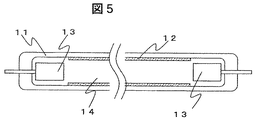
一般に液晶表示装置の光源には、冷陰極蛍光管(CCFL:Cold Cathode Fluorescent Lamp)が用いられる。図5にCCFLの長軸方向での断面図を示した。CCFLはガラス管11の内壁に蛍光体12が塗布され、管両端に電極13を備えた構造である。また、管内には放電媒体14として水銀Hgと希ガス(アルゴンArやネオンNe)が封入されている。
Generally, a cold cathode fluorescent lamp (CCFL) is used as a light source of a liquid crystal display device. FIG. 5 shows a cross-sectional view of the CCFL in the major axis direction. The CCFL has a structure in which a
なお、この種のバックライト(光源と同義)に用いられるCCFLは、室内照明用の蛍光ランプとは異なり、非常に細長い特徴的な形状を有している。一般的に、室内照明用蛍光ランプは管径(管内径)30mm程度、管長1100mm程度である。これに対して、CCFLでは、例えば32インチ液晶表示装置の場合、管径(管内径)4mm程度、管長720mm程度である。CCFLでは、管径が非常に小さいことが特徴である。 The CCFL used for this type of backlight (synonymous with a light source) has a very long and characteristic shape unlike a fluorescent lamp for indoor illumination. In general, fluorescent lamps for indoor lighting have a tube diameter (tube inner diameter) of about 30 mm and a tube length of about 1100 mm. On the other hand, in the CCFL, for example, in the case of a 32-inch liquid crystal display device, the tube diameter (tube inner diameter) is about 4 mm and the tube length is about 720 mm. CCFL is characterized by a very small tube diameter.
このようなCCFLでは、両端の電極13に高電圧を印加することにより点灯する。電圧印加により、電極から放出された電子が水銀Hgを励起し、励起された水銀Hgが基底状態に戻る際に紫外線を放射する。蛍光体はこの紫外線により励起され、可視光を管の外部へ放射する。
In such a CCFL, lighting is performed by applying a high voltage to the
CCFLに備えられた蛍光体12は、発光色が青色系(主発光ピーク波長が400nmから500nm程度)である青色蛍光体と、緑色系(主発光ピーク波長が500nmから600nm程度)である緑色蛍光体と、赤色系(主発光ピーク波長が600nmから650nm程度)である赤色蛍光体の粉末を所定の白色色度になるように混合して構成する。
The
これら3色の蛍光体として一般には、青色蛍光体BaMgAl10O17:Eu2+、緑色蛍光体LaPO4:Tb3+,Ce3+、赤色蛍光体Y2O3:Eu3+が利用されることが多い。また、青色蛍光体として、(Ba,Ca,Mg,Sr)10(PO4)6Cl2:Eu2+(一般にSCA蛍光体と呼ばれる)、 緑色蛍光体として、BaMgAl10O17:Eu2+,Mn2+、赤色蛍光体としてYVO4:Eu3+が利用される場合もある。 In general, blue phosphor BaMgAl 10 O 17 : Eu 2+ , green phosphor LaPO 4 : Tb 3+ , Ce 3+ , and red phosphor Y 2 O 3 : Eu 3+ are used as these three color phosphors. Often. Further, as a blue phosphor, (Ba, Ca, Mg, Sr) 10 (PO 4 ) 6 Cl 2 : Eu 2+ (commonly called SCA phosphor), and as a green phosphor, BaMgAl 10 O 17 : Eu 2+ , Mn 2+ , YVO 4 : Eu 3+ may be used as the red phosphor.
なお、蛍光体材料の通例表記として、「:」より前方は母体材料組成を、後方は発光中心を示し、母体材料の一部の原子を発光中心で置換していることを意味する。例えば、緑色蛍光体LaPO4:Tb3+,Ce3+ではLaPO4が母体材料であり、ランタンLaの一部を発光中心であるテルビウムTbで置換している。また、セリウムCeはTbの発光を増感させる増感剤として添加されている。このことから、LaPO4:Tb3+,Ce3+を(La,Tb,Ce)PO4と記述してもよい。 As a general notation of the phosphor material, the front of “:” indicates the matrix material composition, the back indicates the emission center, and means that some atoms of the matrix material are replaced with the emission center. For example, in the green phosphor LaPO 4 : Tb 3+ , Ce 3+ , LaPO 4 is a base material, and a part of lanthanum La is substituted with terbium Tb, which is the emission center. Cerium Ce is added as a sensitizer that sensitizes the emission of Tb. Therefore, LaPO 4 : Tb 3+ , Ce 3+ may be described as (La, Tb, Ce) PO 4 .
CCFL(光源5)から放射された可視光は、図4に示すように、その直上に配置された拡散板6、プリズムシート7、偏光反射板8などの光学部材を透過してバックライトユニット1に対向する液晶素子2に入射する。また、CCFLからの光の利用効率を向上させるために、CCFLの直下には反射板4が配置され、反射板で反射した光も先述の光学部材を透過して液晶素子2へ入射する。
As shown in FIG. 4, the visible light emitted from the CCFL (light source 5) passes through optical members such as a
一方、液晶素子2は図9に示す断面構造を有する。即ち、対向する一対のガラス基板21(21A、21B)と、その基板の内側表面上にそれぞれ配向膜23が塗布され、さらに基板間に液晶24と、カラーフィルタ25(赤色25A、緑色25B、青色25C)が挟持された構造である。
On the other hand, the
ガラス基板21(21A−21B)間はスペーサ26により保持されている。偏光板22(22A、22B)は、一対の基板21(21A、21B)の外側にそれぞれ配置されている。液晶24は、配向膜23により一様な配向をしており、画素毎に形成された電極群(図9では示していない)に電圧を印加することにより駆動される。電圧が印加されると、液晶はそれによって生じる電界に応じて回転し、液晶層の屈折率が変化することで、光の透過量を調整する。
The glass substrate 21 (21A-21B) is held by a
また、カラーフィルタ25(25A、25B、25C)はバックライトユニット1からの白色光Wを画素毎に赤色光R、緑色光G、青色光Bに分光し、いずれかの光を透過する。液晶表示装置は、このように、バックライトユニットに備えられた光源からの光の透過量を液晶素子で画素毎に調整し、かつ画素毎に赤色、緑色、青色のいずれかの光を透過するカラーフィルタで分光することによりカラー表示を行う。
The color filter 25 (25A, 25B, 25C) splits the white light W from the
上記白色光源に用いられる蛍光ランプの特性改善を目的とした、ランプに塗布された蛍光膜の構造に関する文献として、以下のものが挙げられる。しかし、この文献に示された例では、蛍光ランプの輝度を十分向上させることは出来ていない。 References relating to the structure of the fluorescent film applied to the lamp for the purpose of improving the characteristics of the fluorescent lamp used in the white light source include the following. However, in the example shown in this document, the luminance of the fluorescent lamp cannot be sufficiently improved.
近年、液晶表示装置は、主に大型液晶テレビとしての市場拡大が進んでおり、更なる低コスト化と高画質化が要求されている。これら要求を解決するためには、光源であるCCFLの高輝度化と色度ばらつきの低減が課題である。 In recent years, the market for liquid crystal display devices is mainly expanding as a large-sized liquid crystal television, and further cost reduction and higher image quality are required. In order to solve these requirements, it is a challenge to increase the brightness of CCFL, which is a light source, and to reduce chromaticity variation.
特にCCFLの高輝度化は重要な課題であり、この課題を解決することにより、液晶表示装置の低コスト化を実現できる。例えば、同一輝度のバックライトユニットを設計する場合には、CCFLの本数を従来より削減することが可能となり、インバータ数も同時に削減できることを含めて考えれば、大きな低コスト化を実現できる。また、CCFLの高輝度化により、CCFLと液晶素子との間に介在する光学部材(例えば、輝度向上フィルムなど)を省くことが可能となり、液晶表示装置の低コスト化を実現できる。 In particular, increasing the brightness of CCFLs is an important issue. By solving this problem, it is possible to reduce the cost of a liquid crystal display device. For example, when designing a backlight unit having the same brightness, the number of CCFLs can be reduced as compared with the prior art, and considering that the number of inverters can be reduced at the same time, a great reduction in cost can be realized. Further, by increasing the brightness of the CCFL, it is possible to omit an optical member (for example, a brightness enhancement film) interposed between the CCFL and the liquid crystal element, so that the cost of the liquid crystal display device can be reduced.
一方、CCFLの色度ばらつきは、液晶表示装置の画質に大きく影響する因子であり、その均一化は重要な課題である。液晶表示装置では、光源からの光の透過量を液晶素子により調整し、さらに分光することによって画像を表示するため、人間は液晶素子を通して光源を直視していることになる。従って、CCFLの色度特性が液晶表示装置の色調に直接影響する。 On the other hand, the chromaticity variation of the CCFL is a factor that greatly affects the image quality of the liquid crystal display device, and its uniformity is an important issue. In a liquid crystal display device, an amount of light transmitted from a light source is adjusted by a liquid crystal element, and further an image is displayed by performing spectroscopy, so that a human is looking directly at the light source through the liquid crystal element. Therefore, the chromaticity characteristics of CCFL directly affect the color tone of the liquid crystal display device.
したがって、本発明では、大型化の進む液晶表示装置の低コスト化と高画質化の両立を目的として、CCFLに代表される光源の輝度向上と、色度ばらつき低減を課題とし、以下で述べる手段によりこれらの課題を解決する。 Therefore, in the present invention, for the purpose of achieving both cost reduction and image quality improvement of a liquid crystal display device that is increasing in size, it is necessary to improve luminance of a light source represented by CCFL and reduce chromaticity variation. To solve these problems.
本発明では、光源の高輝度化と、色度ばらつきという課題を解決し、高輝度かつ高画質の画像表示装置を提供することを目的として、以下の手段を用いる。 In the present invention, the following means are used for the purpose of solving the problems of increasing the luminance of a light source and chromaticity variation, and providing an image display device with high luminance and high image quality.
上記目的は、蛍光体粒子を積層した蛍光膜を有し、放電により1次光を発生させ、その1次光により蛍光膜を励起し2次光を得る構造を有する蛍光ランプにおいて、該蛍光膜が少なくとも2種の蛍光体で構成され、そのうち、蛍光膜の厚さ方向において、2次光を取り出す側の、少なくとも最表面層が、第1の発光色の蛍光体層であり、かつその部分以外が、複数の発光色の蛍光体を含む混合蛍光体であることを特徴とする蛍光ランプ、及びそれを用いた画像表示装置により解決することが出来る。 The object is to provide a fluorescent lamp having a fluorescent film in which phosphor particles are laminated, generating primary light by discharge, and exciting the fluorescent film by the primary light to obtain secondary light. Is composed of at least two kinds of phosphors, of which at least the outermost surface layer on the side where secondary light is extracted in the thickness direction of the phosphor film is the phosphor layer of the first emission color, and the portion This can be solved by a fluorescent lamp characterized in that it is a mixed phosphor containing phosphors of a plurality of emission colors, and an image display device using the same.
また、本発明の他の構成として、蛍光体粒子を積層した蛍光膜を有し、放電により1次光を発生させ、その1次光により蛍光膜を励起し2次光を得る構造を有する蛍光ランプにおいて、該蛍光膜が少なくとも2種の蛍光体で構成され、蛍光体全ての重量に対して、膜全体における第1の蛍光体の重量比をxとし、2次光を取り出す側の最表面層での第1の蛍光体の重量比をyとすると、yの範囲が0≦x<y≦1である蛍光膜を有することを特徴とする蛍光ランプ、及びそれを用いた画像表示装置により解決することが出来る。 In addition, as another configuration of the present invention, a fluorescent film having a phosphor film in which phosphor particles are laminated, primary light is generated by discharge, and the phosphor film is excited by the primary light to obtain secondary light. In the lamp, the phosphor film is composed of at least two kinds of phosphors, and the weight ratio of the first phosphor in the whole film to the weight of all the phosphors is x, and the outermost surface on the side from which secondary light is extracted When the weight ratio of the first phosphor in the layer is y, a fluorescent lamp having a phosphor film in which the range of y is 0 ≦ x <y ≦ 1, and an image display device using the same It can be solved.
また、上記の本発明は、第1の発光色の蛍光体が、赤色、緑色、青色のうちいずれかの単色発光蛍光体とすることにより、効果を顕著とすることが出来る。 In the present invention described above, the effect can be made remarkable when the phosphor of the first emission color is any one of red, green and blue.
また、上記の本発明は、第1の発光色の蛍光体の中位粒径d50が、3.0μm以下とすることにより、効果を顕著とすることが出来る。 In the present invention, the effect can be made remarkable when the median particle diameter d50 of the phosphor of the first emission color is 3.0 μm or less.
さらに、上記蛍光ランプにおいて、該蛍光膜がランプの内部表面を間隙なく覆っていることにより、効果を顕著とすることが出来る。 Furthermore, in the fluorescent lamp, the effect can be made remarkable by covering the inner surface of the lamp with no gap.
さらに、上記蛍光ランプにおいて、前記蛍光ランプは、赤色発光蛍光体、緑色発光蛍光体及び青色発光蛍光体を含む蛍光膜を有する冷陰極線構造の白色発光蛍光ランプとした場合、効果を顕著とすることが出来る。 Further, in the above fluorescent lamp, when the fluorescent lamp is a white light emitting fluorescent lamp having a cold cathode line structure having a fluorescent film including a red light emitting phosphor, a green light emitting phosphor and a blue light emitting phosphor, the effect is remarkable. I can do it.
さらに、上記蛍光ランプに使用する蛍光体は、第1の蛍光体以外の蛍光体の中位粒径d50が、1.0μmから10.0μmの範囲とすることで、効果を顕著とすることが出来る。 Furthermore, the effect of the phosphor used in the fluorescent lamp can be made remarkable when the median particle diameter d50 of the phosphor other than the first phosphor is in the range of 1.0 μm to 10.0 μm.
これらの手段が輝度向上及び色度ばらつき低減をもたらす原理を以下に記す。ランプ用蛍光膜の検討の結果、蛍光体を励起する紫外光は、全て利用されているわけではなく、蛍光膜を通過し利用されない紫外光が存在することがわかった。この紫外線の利用率を高めれば、蛍光ランプの輝度を向上させることが可能である。 The principle that these means bring about improvement in luminance and reduction in chromaticity variation will be described below. As a result of studying the fluorescent film for lamps, it was found that not all the ultraviolet light that excites the phosphor is used, but there is ultraviolet light that passes through the fluorescent film and is not used. If the utilization factor of the ultraviolet rays is increased, the luminance of the fluorescent lamp can be improved.
そこで、赤色、青色、緑色蛍光体単色による蛍光膜、及びこれらを混合した白色の蛍光膜について、紫外線利用率を検討した。その結果、単色蛍光膜は、粉体特性の調整により、紫外線利用率を高めることが可能であった。それに対し、混合した白色膜は、各蛍光体の粒径、粒子形状、比重などの粉体特性がそれぞれで異なることから、膜質を向上させにくく、紫外線利用率が単色膜より劣ることがわかった。 Therefore, the utilization rate of ultraviolet rays was examined for phosphor films of single colors of red, blue, and green phosphors, and white phosphor films obtained by mixing them. As a result, the monochromatic phosphor film was able to increase the ultraviolet ray utilization rate by adjusting the powder characteristics. In contrast, the mixed white film has different powder characteristics such as particle size, particle shape and specific gravity of each phosphor, so it is difficult to improve the film quality and the UV utilization rate is inferior to the monochromatic film. .
この結果より、蛍光膜全体を、赤色、青色、緑色の混合膜とするよりも、単色膜の層を部分的に持つ構造とした方が、紫外線利用効率を高めることが出来る。すなわち、蛍光ランプの輝度を高めることが出来る。また、蛍光ランプは、細長い管内壁に蛍光膜を形成するため、完全な単色層を形成するのはコストアップにつながる場合がある。蛍光膜の形成しやすさを検討した結果、蛍光体が混合された状態でも、そのうち一種類の重量比率が高い層があれば、同様に紫外線利用効率を高められる事が出来た。また、これらの効果は、蛍光体の粒径や、膜形状が、前記した特定の要件を満たしたときに、顕著になることがわかった。 From this result, it is possible to increase the efficiency of using the ultraviolet rays when the entire fluorescent film is made to have a structure having a monochromatic film layer rather than a mixed film of red, blue and green. That is, the luminance of the fluorescent lamp can be increased. In addition, since the fluorescent lamp forms a fluorescent film on the inner wall of the elongated tube, forming a complete monochromatic layer may lead to an increase in cost. As a result of investigating the ease of forming the phosphor film, even when the phosphors were mixed, if there was a layer having a high weight ratio, it was possible to increase the efficiency of using ultraviolet rays. Further, it has been found that these effects become remarkable when the particle size of the phosphor and the film shape satisfy the specific requirements described above.
また、三色を混合した膜は、膜形成の時に、各色の特性の違いから、単純計算して設定し混合した各色の比率と、発光する各色の比率が通常異なる。また、膜形成条件によって発光する各色の比率が異なってくる。一つの色を増減させると、他の2色にも影響を与えるため、色の調整が困難である。これらの要因が、蛍光ランプの色度ばらつきとなり、現在の膜構造では容易に低減することが出来ない。 In addition, a film in which three colors are mixed usually has a different ratio of each color that is set by simple calculation and mixed, and a ratio of each color that emits light, due to the difference in characteristics of each color at the time of film formation. Further, the ratio of each color that emits light varies depending on the film forming conditions. When one color is increased or decreased, the other two colors are also affected, making it difficult to adjust the color. These factors cause chromaticity variations of the fluorescent lamp, and cannot be easily reduced with the current film structure.
本発明では、一つの色を独立した層とするため、混合の場合と異なり、膜形成条件の影響を受けにくい。また、その色単独で増減が可能なため、色の調整が容易である。これらのことから、本発明の膜構造では、蛍光ランプの色度ばらつきが低減することがわかった。 In the present invention, since one color is an independent layer, unlike the case of mixing, it is not easily affected by film forming conditions. In addition, since the color can be increased or decreased by itself, color adjustment is easy. From these, it was found that the chromaticity variation of the fluorescent lamp is reduced in the film structure of the present invention.
上記のような原理に基づくため、本発明の効果は、蛍光ランプの形状や励起方法に限定されず有効である。前述したCCFLランプは一例であり、例えば平面の形状を持つ蛍光ランプや、熱陰極管(HCFL)(Hot Cathode Fluorescent Lamp)や、Xe放電による紫外光を励起源として用いる蛍光ランプなどの場合でも有効である。 Based on the above principle, the effects of the present invention are not limited to the shape of the fluorescent lamp and the excitation method, but are effective. The CCFL lamp described above is an example, and is effective even in the case of, for example, a fluorescent lamp having a planar shape, a hot cathode fluorescent lamp (HCFL), or a fluorescent lamp using ultraviolet light from an Xe discharge as an excitation source. It is.
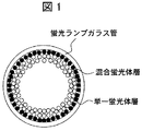
また、本発明の効果は、蛍光体の種類に限定されず有効である。前述した蛍光体は一例であり、他の種類の蛍光体を用いた場合も有効である。なお、従来の蛍光管では、ガラス管の内面に蛍光体の保護層として発光しないY2O3の微粒子をコーティングしていた。本発明のように、蛍光体の単層膜を用いることによってこのY2O3の微粒子を省略できるというメリットを有する。逆に言えば、本発明にしたがって、単層の蛍光膜を形成しても、従来用いていた発光しないY2O3を省略すれば、従来の蛍光管に比して製造コストを上昇させることなく輝度の向上、色度のバラつきを抑えることが出来る。 The effect of the present invention is not limited to the type of phosphor, but is effective. The phosphor described above is an example, and it is also effective when other types of phosphors are used. In the conventional fluorescent tube, the inner surface of the glass tube is coated with Y 2 O 3 fine particles which do not emit light as a fluorescent protective layer. As in the present invention, the use of a single layer film of phosphor has the advantage that the fine particles of Y 2 O 3 can be omitted. In other words, according to the present invention, even if a single-layer fluorescent film is formed, if Y 2 O 3 that does not emit light, which has been conventionally used, is omitted, the manufacturing cost is increased as compared with a conventional fluorescent tube. It is possible to improve brightness and suppress chromaticity variations.
本発明では以上の手段を用いることにより、光源の輝度向上と、色度ばらつきの低減を両立することができる。また、このような光源を用いることにより、画像表示装置において、高画質な画像表示装置を得ることができる。 In the present invention, by using the above-described means, it is possible to achieve both improvement in luminance of the light source and reduction in chromaticity variation. Moreover, by using such a light source, a high-quality image display device can be obtained in the image display device.
以下、本発明の実施例を図面を用いて詳細に説明する。 Hereinafter, embodiments of the present invention will be described in detail with reference to the drawings.
本発明の構成の画像表示装置を以下の方法で作製し、その特性を評価した。本実施例における液晶表示装置は、図4に示すようにバックライトユニット1と液晶素子2とから構成される。さらに、バックライトユニット1は、白色光源5とそれを点灯するための駆動回路9(インバータ)、筐体3、反射板4、拡散板6、プリズムシート7、偏光反射板8から構成される。なお、上記バックライトユニットは例であり、上記全ての構成部品を含まなくてもよいし、他の構成部品を加えてもよい。要するにバックライトユニットは、画像を形成するために液晶素子2を照明するものを言う。
An image display device having the configuration of the present invention was produced by the following method, and its characteristics were evaluated. The liquid crystal display device according to this embodiment includes a
本実施例では、白色光源として図5に示したCCFLを用いた。このとき、従来例として、赤色、緑色、青色を混合した蛍光膜を用いたCCFLを作製した。本発明の実施例1として、緑色蛍光体の蛍光膜を単色膜の層として独立させ、赤色、緑色、青色を混合した蛍光膜の層にさらに加えた構造のCCFLを作製した。以下、CCFLの作製と、このCCFLを用いたIPSモードの液晶表示装置の作製について述べる。 In this example, the CCFL shown in FIG. 5 was used as the white light source. At this time, as a conventional example, a CCFL using a fluorescent film in which red, green and blue were mixed was produced. As Example 1 of the present invention, a CCFL having a structure in which a phosphor film of a green phosphor was made independent as a monochromatic film layer and further added to a phosphor film layer in which red, green, and blue were mixed was produced. The production of CCFL and the production of an IPS mode liquid crystal display device using this CCFL will be described below.
CCFLの作製手順を以下に示す。まず、ビークルと呼ばれるニトロセルロースと酢酸ブチルから成る有機溶剤にアルミナなどの結着材、各色蛍光体材料を混合する。この混合液をサスペンジョンと称する。従来例作製のために、蛍光体として、青色蛍光体BaMgAl10O17:Eu2+、緑色蛍光体LaPO4:Tb3+,Ce3+、赤色蛍光体Y2O3:Eu3+を混合したサスペンジョンを用いた。また、本発明の実施例1作製のために、緑色蛍光体LaPO4:Tb3+,Ce3+のサスペンジョンを作製した。 The CCFL production procedure is shown below. First, a binder such as alumina and each color phosphor material are mixed in an organic solvent composed of nitrocellulose and butyl acetate called a vehicle. This liquid mixture is called a suspension. For the preparation of the conventional example, blue phosphor BaMgAl 10 O 17 : Eu 2+ , green phosphor LaPO 4 : Tb 3+ , Ce 3+ , red phosphor Y 2 O 3 : Eu 3+ are mixed as phosphors Suspension was used. In addition, a suspension of green phosphor LaPO 4 : Tb 3+ , Ce 3+ was produced for the production of Example 1 of the present invention.
これら全ての蛍光体の粒径は、コールターメーターで測定した中位粒径d50が、1.0μmから10.0μmの範囲にあるものを用いた。次に、このサスペンジョンに、予め洗浄したガラス管の片側を浸し、もう一方の側よりポンプで吸入し、サスペンジョンを引き上げることによりガラス管内壁に蛍光体を塗布した。従来例では、三色混合のサスペンジョンを用いて1層の蛍光体層を形成した。実施例1として、緑色蛍光体のサスペンジョンによる層、及び三色混合の蛍光体層の2層を形成した。 As the particle diameters of all these phosphors, those having a median particle diameter d50 measured with a Coulter meter in the range of 1.0 μm to 10.0 μm were used. Next, one side of the glass tube washed beforehand was immersed in this suspension, and it suck | inhaled with the pump from the other side, and the fluorescent substance was apply | coated to the inner wall of the glass tube by pulling up suspension. In the conventional example, a single phosphor layer was formed using a suspension of three colors. As Example 1, two layers of a green phosphor suspension layer and a three-color phosphor layer were formed.
ガラス管の材質はコパールガラスであり、管径は3mmである。そして、ガラス管をベーキング(焼成)することにより、蛍光体を管内壁に固着させた。その後、電極を取り付け、ガラス管の片側を封止する。封止した側の逆側からアルゴンArやネオンNeなどの希ガスを注入し、排気することでガス圧を調整した。さらに水銀を注入後、ガラス管をシールした。最後に、このガラス管を一定時間点灯させてエージング処理を行った。 The material of the glass tube is copal glass, and the tube diameter is 3 mm. Then, the glass tube was baked (fired) to fix the phosphor to the inner wall of the tube. Then, an electrode is attached and the one side of a glass tube is sealed. The gas pressure was adjusted by injecting and exhausting a rare gas such as argon Ar or neon Ne from the opposite side of the sealed side. Further, after injecting mercury, the glass tube was sealed. Finally, the glass tube was turned on for a certain period of time to perform an aging process.
次にバックライトユニットの組み立てを図4で説明する。上記完成した複数本のCCFL5を金属筐体3に配置した。液晶テレビのような高輝度を要求される液晶表示装置では、CCFL複数本を平面的に並べて配置する直下方式が採用される。
Next, the assembly of the backlight unit will be described with reference to FIG. The plurality of completed
金属筐体3とCCFL5との間には、CCFLから筐体側に出射した光を効率よく利用するための反射板4を配置した。また、液晶表示装置の輝度面内分布を抑えるために、CCFLの直上に拡散板6を配置した。さらに、液晶表示装置の輝度向上を目的として、プリズムシート7や偏光反射板8を配置した。CCFLにはインバータ9が接続され、CCFLの点灯制御はインバータの駆動によって行われた。なお、これらをまとめてバックライトユニット1と称する。
Between the
バックライトユニット1の直上には、バックライト(白色光源CCFL)からの光の透過量を調整し、画素毎に赤色、緑色、青色に光を分光するカラーフィルタを有する液晶素子2を配置した。
Directly above the
液晶素子の断面概略図は図9に示す通りである。基板21には、通常厚みが0.5mmのガラス基板を利用する。一方の基板21A上には、画素毎に電極(図9では図示されていない)を形成し、また、これら電極に電圧を供給する薄膜トランジスタ(TFT:Thin Film Transistor)を形成した。他方の基板21Bには、画素毎にカラーフィルタ25(赤色25A、緑色25B、青色25C)を形成した。そして、これら一対の基板表面には液晶分子を配列させるための配向膜23を形成し、さらに基板間に液晶24を挟持した。また、基板の外側には偏光板22(22A、22B)を配置した。最後に、バックライトユニット1と液晶素子2とを組み合わせ、筐体10でカバーすることにより液晶表示装置を得た。
A schematic cross-sectional view of the liquid crystal element is as shown in FIG. As the
本実施例1により、図1に示す本発明の膜構造を作製した。この場合、図1の単一蛍光体層は緑色蛍光体である。従来例と、実施例1との、白色輝度を測定し、従来例を100として相対輝度を示した結果を図2に示す。図2における白色の色温度は7000Kである。実施例1では、従来例より輝度が向上していることがわかる。 According to Example 1, the film structure of the present invention shown in FIG. In this case, the single phosphor layer in FIG. 1 is a green phosphor. FIG. 2 shows the result of measuring the white luminance between the conventional example and Example 1 and showing the relative luminance with the conventional example being 100. The white color temperature in FIG. 2 is 7000K. In Example 1, it can be seen that the luminance is improved as compared with the conventional example.
また、これらの作製を複数行い、各液晶表示装置の赤色、緑色、青色、白色の色度値を測定した結果、実施例1の方が、従来例より、色のばらつきが少なかった。この色度値はCIEの(x、y)を測定することによって得ることが出来る。また、実施例1の蛍光膜は、切れ目無く蛍光ランプガラス管を覆っているものの方が、切れ目による隙間や孔などの間隙があるものよりも輝度が高かった。以上のように緑の単層膜を形成することによって紫外線の利用率、言い換えれば、紫外線の蛍光管外への透過率を下げることが出来る。 In addition, as a result of carrying out a plurality of these productions and measuring the chromaticity values of red, green, blue, and white of each liquid crystal display device, the variation in color in Example 1 was less than that in the conventional example. This chromaticity value can be obtained by measuring CIE (x, y). In addition, the phosphor film of Example 1 was higher in luminance when it covered the fluorescent lamp glass tube without a break than when there was a gap such as a gap or a hole such as a hole. By forming a green single layer film as described above, the utilization factor of ultraviolet rays, in other words, the transmittance of ultraviolet rays to the outside of the fluorescent tube can be lowered.
これより、本発明により、CCFLの高輝度化と、色度ばらつきの低減とを両立することができることが示された。また、このような光源を用いることで、低コスト化と高画質化を両立した高品位な液晶表示装置を得ることができる。 From this, it was shown that the present invention can achieve both high brightness of CCFL and reduction of chromaticity variation. Further, by using such a light source, a high-quality liquid crystal display device that achieves both low cost and high image quality can be obtained.
実施例1と同様の方法で、実施例2を作製した。実施例2と、実施例1との相違は、青蛍光体BaMgAl10O17:Eu2+の単独のサスペンジョンを用いて、青色蛍光体のサスペンジョンによる層、及び三色混合の蛍光体層の2層を形成したことである。
Example 2 was produced in the same manner as in Example 1. The difference between Example 2 and Example 1 is that a single suspension of blue phosphor BaMgAl 10 O 17 : Eu 2+ is used, and a blue phosphor suspension layer and a three-color
また、全ての蛍光体の粒径は、コールターメーターで測定した中位粒径d50が、1.0μmから10.0μmの範囲にあるものを用いた。本実施例2により、図1に示す本発明の膜構造を作製した。この場合、図1の単一蛍光体層は青色蛍光体である。 In addition, as the particle diameters of all the phosphors, those having a median particle diameter d50 measured by a Coulter meter in the range of 1.0 μm to 10.0 μm were used. According to Example 2, the film structure of the present invention shown in FIG. In this case, the single phosphor layer in FIG. 1 is a blue phosphor.
従来例と、実施例2との、白色輝度を測定し、従来例を100として相対輝度を示した結果を図2に示す。実施例2では、従来例より輝度が向上していることがわかる。また、これらの作製を複数行い、各液晶表示装置の赤色、緑色、青色、白色の色度値を測定した結果、実施例2の方が、従来例より、色のばらつきが少なかった。 FIG. 2 shows the results of measuring the white luminance between the conventional example and Example 2, and showing the relative luminance with the conventional example being 100. In Example 2, it turns out that the brightness | luminance is improving rather than a prior art example. In addition, as a result of performing a plurality of these preparations and measuring the chromaticity values of red, green, blue, and white of each liquid crystal display device, the variation in the color of Example 2 was less than that of the conventional example.
また、実施例2の蛍光膜は、切れ目無く蛍光ランプガラス管を覆っているものの方が、切れ目による隙間や孔などの間隙があるものよりも輝度が高かった。 Further, the brightness of the fluorescent film of Example 2 covering the fluorescent lamp glass tube without a break was higher than that having a gap such as a gap or a hole.
これより、本発明により、CCFLの高輝度化と、色度ばらつきの低減とを両立することができることが示された。また、このような光源を用いることで、低コスト化と高画質化を両立した高品位な液晶表示装置を得ることができる。 From this, it was shown that the present invention can achieve both high brightness of CCFL and reduction of chromaticity variation. Further, by using such a light source, a high-quality liquid crystal display device that achieves both low cost and high image quality can be obtained.
実施例1と同様の方法で、実施例3を作製した。実施例3と、実施例1との相違は、赤色蛍光体Y2O3:Eu3+の単独のサスペンジョンを用いて、赤色蛍光体のサスペンジョンによる層、及び三色混合の蛍光体層の2層を形成したことである。 Example 3 was produced in the same manner as in Example 1. The difference between Example 3 and Example 1 is that a single phosphor suspension of red phosphor Y 2 O 3 : Eu 3+ is used, a red phosphor suspension layer, and a three-color mixed phosphor layer. That the layer was formed.
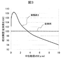
このとき、赤色蛍光体単一の層においては、赤色蛍光体の粒径を、コールターメーターで測定した中位粒径d50が、0.05μm〜10μmの範囲で変化させ、その特性を比較した。また、混合層においては、赤色蛍光体を含む全ての蛍光体の粒径は、コールターメーターで測定した中位粒径d50が、1.0μmから10.0μmの範囲にある、一定の値の固定した粒径のものを用いた。 At this time, in the single layer of the red phosphor, the particle size of the red phosphor was changed in the range of 0.05 to 10 μm in the median particle size d50 measured with a Coulter meter, and the characteristics were compared. In the mixed layer, the particle diameters of all phosphors including red phosphors are fixed particles having a fixed value in which the median particle diameter d50 measured with a Coulter meter is in the range of 1.0 μm to 10.0 μm. The diameter was used.
本実施例3により、図1に示す本発明の膜構造を作製した。この場合、図1の単一蛍光体層は赤色蛍光体である。従来例と、実施例3との、白色輝度を測定し、従来例を100として相対輝度を示した結果を図3に示す。実施例3では、中位粒径d50が3.0μm以下のものにおいて、従来例より輝度が向上していることがわかる。 According to Example 3, the film structure of the present invention shown in FIG. In this case, the single phosphor layer in FIG. 1 is a red phosphor. FIG. 3 shows the results of measuring the white luminance of the conventional example and Example 3 and showing the relative luminance with the conventional example being 100. In Example 3, it can be seen that the luminance is improved over the conventional example when the median particle size d50 is 3.0 μm or less.
また、これらの作製を複数行い、各液晶表示装置の赤色、緑色、青色、白色の色度値を測定した結果、実施例3の方が、従来例より、色のばらつきが少なかった。また、実施例3の蛍光膜は、切れ目無く蛍光ランプガラス管を覆っているものの方が、切れ目による隙間や孔などの間隙があるものよりも輝度が高かった。これより、本発明により、CCFLの高輝度化と、色度ばらつきの低減とを両立することができることが示された。また、このような光源を用いることで、低コスト化と高画質化を両立した高品位な液晶表示装置を得ることができる。 In addition, as a result of performing a plurality of these productions and measuring the chromaticity values of red, green, blue, and white of each liquid crystal display device, the variation in color in Example 3 was less than that in the conventional example. In addition, the phosphor film of Example 3 was higher in luminance when it covered the fluorescent lamp glass tube without a break than when there was a gap such as a gap or a hole such as a hole. From this, it was shown that the present invention can achieve both high brightness of CCFL and reduction of chromaticity variation. Further, by using such a light source, a high-quality liquid crystal display device that achieves both low cost and high image quality can be obtained.
本実施例では独立層としての赤蛍光体について粒径を3.0μm以下とすることによる効果を記載した。しかし、実施例1で用いた独立層としての緑蛍光体、実施例2で用いた独立層としての青蛍光体の粒径を3.0μm以下とすることによっても効果が得られることはもちろんである。ただし、緑または青の蛍光体を独立層として用いる場合は粒径を3.0μm以下としなくとも効果が得られるという特徴を有する。 In this example, the effect of setting the particle diameter to 3.0 μm or less for the red phosphor as the independent layer was described. However, it is a matter of course that the effect can also be obtained by setting the particle size of the green phosphor as the independent layer used in Example 1 and the blue phosphor as the independent layer used in Example 2 to 3.0 μm or less. . However, when a green or blue phosphor is used as the independent layer, the effect is obtained even if the particle size is not set to 3.0 μm or less.
本実施例4は、実施例1乃至3と比較して、光源の種類が異なる。実施例1乃至3ではCCFLを用いたが、本実施例では図6に示したHCFL(Hot Cathode Fluorescent Lamp、 熱陰極管)を用いた。HCFLに利用する蛍光体は、実施例1乃至3と同様である。 The fourth embodiment differs from the first to third embodiments in the type of light source. In Examples 1 to 3, CCFL was used, but in this example, HCFL (Hot Cathode Fluorescent Lamp, hot cathode tube) shown in FIG. 6 was used. The phosphor used for HCFL is the same as in Examples 1 to 3.
HCFLは図6に示すように、CCFLに類似した構造であり、金属電極部13がフィラメント電極である点で大きく異なる。HCFLの両電極間に電圧を印加するとフィラメントから熱電子が放出され、この熱電子により水銀が励起され紫外線を放射する。
As shown in FIG. 6, HCFL has a structure similar to CCFL, and is greatly different in that the
従来例の蛍光膜を用いたHCFLと、実施例4との、白色輝度を測定した結果、実施例1乃至3と同様に、従来例より輝度が向上していることがわかった。また、これらの作製を複数行い、各液晶表示装置の赤色、緑色、青色、白色の色度値を測定した結果、実施例4の方が、従来例より、色のばらつきが少なかった。また、実施例4の蛍光膜は、切れ目無く蛍光ランプガラス管を覆っているものの方が、切れ目による隙間や孔などの間隙があるものよりも輝度が高かった。 As a result of measuring the white luminance of the HCFL using the fluorescent film of the conventional example and Example 4, it was found that the luminance was improved as compared with the conventional example as in Examples 1 to 3. In addition, as a result of performing a plurality of these productions and measuring the chromaticity values of red, green, blue, and white of each liquid crystal display device, the variation in color in Example 4 was less than that in the conventional example. Further, the brightness of the fluorescent film of Example 4 covering the fluorescent lamp glass tube without a break was higher than that having a gap such as a gap or a gap such as a hole.
これより、本発明により、HCFLにおいても、高輝度化と、色度ばらつきの低減とを両立することができることが示された。また、このような光源を用いることで、低コスト化と高画質化を両立した高品位な液晶表示装置を得ることができる。 Thus, according to the present invention, it has been shown that high brightness and reduction in chromaticity variation can both be achieved in HCFL. Further, by using such a light source, a high-quality liquid crystal display device that achieves both low cost and high image quality can be obtained.
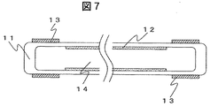
本実施例5は、実施例1乃至3と比較して、光源の種類が異なる。実施例1乃至3ではCCFLを用いたが、本実施例では図7に示したEEFL(External Electrode Fluorescent Lamp、 外部電極管)を用いた。EEFLに利用する蛍光体は、実施例1乃至3と同様である。 The fifth embodiment is different from the first to third embodiments in the type of light source. In Examples 1 to 3, CCFL was used, but in this example, EEFL (External Electrode Fluorescent Lamp, external electrode tube) shown in FIG. 7 was used. The phosphor used for EEFL is the same as in Examples 1 to 3.
EEFLの作製は、CCFLと比較して、電極部の形成が異なる。EEFLでは、ガラス管に蛍光体を塗布後、ガラス管の一方を封じ、排気した後、放電媒体である水銀を導入し、ガラス管の他方を封じる。その後、例えば銅テープのようなフレキシブルな電極をガラス管の外部に配置する。 Production of EEFL differs from CCFL in the formation of electrode parts. In EEFL, after applying a phosphor to a glass tube, one side of the glass tube is sealed and evacuated, then mercury as a discharge medium is introduced and the other side of the glass tube is sealed. Thereafter, a flexible electrode such as a copper tape is disposed outside the glass tube.
このようなEEFLではガラス管自体がコンデンサーの役割を果たすためにバラストコンデンサが不要となり、一つのインバータ9により複数本のランプ5を点灯する多点灯駆動が可能である。このことは、CCFLに比べインバータ数を大きく削減できることから低コスト化が期待できる。
In such an EEFL, since the glass tube itself serves as a capacitor, a ballast capacitor is not required, and multiple lighting driving in which a plurality of
従来例の蛍光膜を用いたEEFLと、実施例5との、白色輝度を測定した結果、実施例1乃至3と同様に、従来例より輝度が向上していることがわかった。また、これらの作製を複数行い、各液晶表示装置の赤色、緑色、青色、白色の色度値を測定した結果、実施例5の方が、従来例より、色のばらつきが少なかった。また、実施例5の蛍光膜は、切れ目無く蛍光ランプガラス管を覆っているものの方が、切れ目による隙間や孔などの間隙があるものよりも輝度が高かった。 As a result of measuring the white luminance of EEFL using the fluorescent film of the conventional example and Example 5, it was found that the luminance was improved as compared with the conventional example as in Examples 1 to 3. In addition, as a result of performing a plurality of these productions and measuring the chromaticity values of red, green, blue, and white of each liquid crystal display device, the variation in Example 5 was less than that in the conventional example. In addition, the fluorescent film of Example 5 was higher in luminance when the fluorescent lamp glass tube was covered without a break than when there was a gap such as a gap or a hole.
これより、本発明により、EEFLにおいても、高輝度化と、色度ばらつきの低減とを両立することができることが示された。また、このような光源を用いることで、低コスト化と高画質化を両立した高品位な液晶表示装置を得ることができる。 Thus, according to the present invention, it has been shown that even in EEFL, it is possible to achieve both high luminance and reduction in chromaticity variation. Further, by using such a light source, a high-quality liquid crystal display device that achieves both low cost and high image quality can be obtained.
本実施例6は、実施例1乃至3と比較して、光源の種類が異なる。実施例1乃至3ではCCFLを用いたが、本実施例では図8に示した平面光源を用いた。EEFLに利用する蛍光体は、実施例1乃至3と同様である。 The sixth embodiment is different from the first to third embodiments in the type of light source. Although CCFL was used in Examples 1 to 3, a planar light source shown in FIG. 8 was used in this example. The phosphor used for EEFL is the same as in Examples 1 to 3.
平面光源は、図8に示すように、蛍光体12を備えた密閉容器15(背面ガラス15A、前面ガラス15B)と、その背面ガラス上に配置された電極13(
13A、13B)から構成される構造を有する。蛍光体の単色膜は前面ガラス15B側に形成した。さらに電極上には、誘電体16が配置される。そして、この密閉容器内に放電媒体14が封入されている。放電媒体は、平面光源の種類によって異なるが、Xeガスを利用している光源や、水銀を利用している光源もある。
As shown in FIG. 8, the planar light source includes a sealed container 15 (back glass 15A, front glass 15B) including a
13A, 13B). The monochromatic film of the phosphor was formed on the front glass 15B side. Further, a dielectric 16 is disposed on the electrode. The
従来例の蛍光膜を用いた平面光源と、実施例6との、白色輝度を測定した結果、実施例1乃至3と同様に、従来例より輝度が向上していることがわかった。また、これらの作製を複数行い、各液晶表示装置の赤色、緑色、青色、白色の色度値を測定した結果、実施例6の方が、従来例より、色のばらつきが少なかった。また、実施例6の蛍光膜は、切れ目無く前面ガラスを覆っているものの方が、切れ目による隙間や孔などの間隙があるものよりも輝度が高かった。 As a result of measuring the white luminance of the planar light source using the fluorescent film of the conventional example and Example 6, it was found that the luminance was improved as compared with the conventional example as in Examples 1 to 3. In addition, as a result of making a plurality of these and measuring the chromaticity values of red, green, blue, and white of each liquid crystal display device, the variation in the color of Example 6 was less than that of the conventional example. In addition, the phosphor film of Example 6 in which the front glass was covered without a break was higher in luminance than that having gaps such as gaps or holes.
これより、本発明により、平面光源においても、高輝度化と、色度ばらつきの低減とを両立することができることが示された。また、このような光源を用いることで、低コスト化と高画質化を両立した高品位な液晶表示装置を得ることができる。 From this, it was shown that the present invention can achieve both high luminance and reduced chromaticity variation even in a planar light source. Further, by using such a light source, a high-quality liquid crystal display device that achieves both low cost and high image quality can be obtained.
1…バックライトユニット、
2…液晶素子、
3…筐体(下)、
4…反射板、
5…光源(例えばCCFL)、
6…拡散板、
7…プリズムシート、
8…偏光反射板、
9…インバータ、
10…筐体(上)、
11…ガラス管、
12…蛍光体、
13…電極、
14…放電媒体、
15…密閉容器(15A、15B)、
16…隔壁、
21、31…ガラス基板、
22、32…偏光板、
23、33…配向膜、
24、34…液晶、
25(25A、25B、25C)…カラーフィルタ(赤色、緑色、青色)、
26…スペーサ、
27、37…画素電極。
1 ... Backlight unit,
2 ... Liquid crystal element,
3 ... Case (bottom),
4 ... reflector,
5 ... Light source (eg CCFL),
6 ... diffusion plate,
7 ... Prism sheet,
8: Polarizing reflector,
9: Inverter,
10 ... Case (top),
11 ... Glass tube,
12 ... phosphor,
13 ... electrodes
14 ... discharge medium,
15 ... Sealed container (15A, 15B),
16 ... partition wall,
21, 31 ... Glass substrate,
22, 32 ... Polarizing plate,
23, 33 ... alignment film,
24, 34 ... Liquid crystal,
25 (25A, 25B, 25C) ... color filters (red, green, blue),
26 ... spacer,
27, 37: Pixel electrodes.
Claims (13)
前記蛍光ランプは蛍光体粒子を積層した蛍光膜を有し、放電により1次光を発生させ、その1次光により蛍光膜を励起し2次光を得る構造を有する蛍光ランプであって、前記蛍光膜が少なくとも2種の蛍光体で構成され、そのうち、前記蛍光膜の厚さ方向において、2次光を取り出す側の、少なくとも最表面層が、第1の蛍光体による蛍光体層であり、かつその部分以外が、複数の蛍光体を含む混合蛍光体である蛍光ランプであることを特徴とする液晶表示装置。 A liquid crystal display device including a backlight unit using a fluorescent lamp as a liquid crystal element and a light source,
The fluorescent lamp has a fluorescent film in which phosphor particles are laminated, generates a primary light by discharge, and has a structure for obtaining a secondary light by exciting the fluorescent film by the primary light, The phosphor film is composed of at least two kinds of phosphors, of which at least the outermost surface layer on the side where secondary light is extracted in the thickness direction of the phosphor film is a phosphor layer made of the first phosphor, In addition, a liquid crystal display device characterized in that a portion other than the portion is a fluorescent lamp that is a mixed phosphor including a plurality of phosphors.
前記蛍光ランプは蛍光体粒子を積層した蛍光膜を有し、放電により1次光を発生させ、その1次光により蛍光膜を励起し2次光を得る構造を有する蛍光ランプであって、前記蛍光膜が少なくとも2種の蛍光体で構成され、前記蛍光体全ての重量に対して、膜全体における第1の蛍光体の重量比をxとし、2次光を取り出す側の最表面層での前記第1の蛍光体の重量比をyとすると、yの範囲が0≦x<y≦1である蛍光膜を有する蛍光ランプであることを特徴とする液晶表示装置。 A liquid crystal display device including a backlight unit using a fluorescent lamp as a liquid crystal element and a light source,
The fluorescent lamp has a fluorescent film in which phosphor particles are laminated, generates a primary light by discharge, and has a structure for obtaining a secondary light by exciting the fluorescent film by the primary light, The phosphor film is composed of at least two kinds of phosphors, and the weight ratio of the first phosphor in the whole film is x with respect to the weight of all of the phosphors. A liquid crystal display device comprising a fluorescent lamp having a fluorescent film in which a range of y is 0 ≦ x <y ≦ 1, where y is a weight ratio of the first phosphor.
Priority Applications (3)
| Application Number | Priority Date | Filing Date | Title |
|---|---|---|---|
| JP2007058911A JP2008226492A (en) | 2007-03-08 | 2007-03-08 | Fluorescent lamp and image display device using it |
| CNA200810005516XA CN101261920A (en) | 2007-03-08 | 2008-02-04 | Fluorescent lamp and imaging device usign the same |
| US12/033,907 US20080218664A1 (en) | 2007-03-08 | 2008-02-20 | Fluorescent lamp and imaging device usign the same |
Applications Claiming Priority (1)
| Application Number | Priority Date | Filing Date | Title |
|---|---|---|---|
| JP2007058911A JP2008226492A (en) | 2007-03-08 | 2007-03-08 | Fluorescent lamp and image display device using it |
Publications (2)
| Publication Number | Publication Date |
|---|---|
| JP2008226492A true JP2008226492A (en) | 2008-09-25 |
| JP2008226492A5 JP2008226492A5 (en) | 2009-08-20 |
Family
ID=39741255
Family Applications (1)
| Application Number | Title | Priority Date | Filing Date |
|---|---|---|---|
| JP2007058911A Abandoned JP2008226492A (en) | 2007-03-08 | 2007-03-08 | Fluorescent lamp and image display device using it |
Country Status (3)
| Country | Link |
|---|---|
| US (1) | US20080218664A1 (en) |
| JP (1) | JP2008226492A (en) |
| CN (1) | CN101261920A (en) |
Cited By (2)
| Publication number | Priority date | Publication date | Assignee | Title |
|---|---|---|---|---|
| WO2010027006A1 (en) | 2008-09-03 | 2010-03-11 | 日本電気株式会社 | Gesture input operation device, method, program, and portable device |
| US9494284B2 (en) | 2014-03-05 | 2016-11-15 | Sharp Kabushiki Kaisha | Light source device and illumination apparatus |
Families Citing this family (1)
| Publication number | Priority date | Publication date | Assignee | Title |
|---|---|---|---|---|
| TW201237389A (en) * | 2011-03-15 | 2012-09-16 | Lextar Electronics Corp | Die inspection machine with multi-wave domain searching light source |
Family Cites Families (13)
| Publication number | Priority date | Publication date | Assignee | Title |
|---|---|---|---|---|
| JPS5645564A (en) * | 1979-09-21 | 1981-04-25 | Hitachi Ltd | Reflex fluorescent lamp |
| JPS56143654A (en) * | 1980-04-08 | 1981-11-09 | Toshiba Corp | Fluorescent lamp |
| US4393330A (en) * | 1980-10-20 | 1983-07-12 | North American Philips Electric Corp. | Method for effectively contacting manganese-activated zinc silicate phosphor with antimony oxide during phosphor coating, and resulting lamp |
| US4623816A (en) * | 1985-04-22 | 1986-11-18 | General Electric Company | Fluorescent lamp using multi-layer phosphor coating |
| US4847533A (en) * | 1986-02-05 | 1989-07-11 | General Electric Company | Low pressure mercury discharge fluorescent lamp utilizing multilayer phosphor combination for white color illumination |
| US4940918A (en) * | 1989-07-24 | 1990-07-10 | Gte Products Corporation | Fluorescent lamp for liquid crystal backlighting |
| JP3149444B2 (en) * | 1991-01-30 | 2001-03-26 | 東芝ライテック株式会社 | Low pressure mercury vapor discharge lamp |
| US5854533A (en) * | 1992-10-19 | 1998-12-29 | Gte Products Corporation | Fluorescent lamps with high color-rendering and high brightness |
| US5731659A (en) * | 1996-05-13 | 1998-03-24 | General Electric Company | Fluorescent lamp with phosphor coating of multiple layers |
| DE10129630A1 (en) * | 2001-06-20 | 2003-01-02 | Philips Corp Intellectual Pty | Low pressure gas discharge lamp with fluorescent coating |
| US20060113885A1 (en) * | 2004-11-29 | 2006-06-01 | Keiji Iimura | Discharge fluorescen apparatus including fluorescent fibers |
| JP2006208805A (en) * | 2005-01-28 | 2006-08-10 | Hitachi Displays Ltd | Liquid crystal display device |
| JP4892230B2 (en) * | 2005-11-28 | 2012-03-07 | 株式会社 日立ディスプレイズ | Liquid crystal display |
-
2007
- 2007-03-08 JP JP2007058911A patent/JP2008226492A/en not_active Abandoned
-
2008
- 2008-02-04 CN CNA200810005516XA patent/CN101261920A/en active Pending
- 2008-02-20 US US12/033,907 patent/US20080218664A1/en not_active Abandoned
Cited By (3)
| Publication number | Priority date | Publication date | Assignee | Title |
|---|---|---|---|---|
| WO2010027006A1 (en) | 2008-09-03 | 2010-03-11 | 日本電気株式会社 | Gesture input operation device, method, program, and portable device |
| US9494284B2 (en) | 2014-03-05 | 2016-11-15 | Sharp Kabushiki Kaisha | Light source device and illumination apparatus |
| US10190733B2 (en) | 2014-03-05 | 2019-01-29 | Sharp Kabushiki Kaisha | Light source device and illumination apparatus |
Also Published As
| Publication number | Publication date |
|---|---|
| US20080218664A1 (en) | 2008-09-11 |
| CN101261920A (en) | 2008-09-10 |
Similar Documents
| Publication | Publication Date | Title |
|---|---|---|
| CN100397189C (en) | Liquid crystal display device | |
| JP4363467B2 (en) | Phosphor, fluorescent lamp using the same, and display device and illumination device using the fluorescent lamp | |
| JP2008166299A (en) | Liquid crystal image screen with white color light source | |
| JP4572687B2 (en) | Backlight device and liquid crystal display device | |
| TWI223830B (en) | Fluorescent lamp and liquid crystal display device having the same | |
| US20060001353A1 (en) | Flat fluorescent lamp | |
| US7940354B2 (en) | Liquid crystal display device | |
| JP4892230B2 (en) | Liquid crystal display | |
| JP2008226492A (en) | Fluorescent lamp and image display device using it | |
| KR101450785B1 (en) | Fluorescent Lamp, Backlight Assembly Having The Same And Display Device Having The Same | |
| US20070069615A1 (en) | Surface light source device | |
| JP2009161731A (en) | Fluorescent mixture for fluorescent lamp, fluorescent lamp for display device, backlight assembly having it, and display device | |
| JP2009123406A (en) | External electrode type rare gas fluorescent lamp | |
| JP2009102502A (en) | Fluorescent lamp and liquid crystal display device using the same | |
| JP2007200571A (en) | Fluorescent lamp and illumination device | |
| US8310141B2 (en) | Fluorescent lamp, light source apparatus and display apparatus | |
| JP2009295541A (en) | Fluorescent lamp and liquid crystal display device | |
| US7903202B2 (en) | Liquid crystal display device | |
| TWI260449B (en) | Liquid crystal display that shows colors by fluorescent layer | |
| KR100784710B1 (en) | Back light unit using discharge gas emitting long wave length uv | |
| JP3601775B2 (en) | Backlight device and liquid crystal display device | |
| TWI345800B (en) | Flat light source module | |
| KR20070046423A (en) | Backlight lamp and backlight assembly for liquid crystal display | |
| KR20100116967A (en) | Liquid crystal display device module | |
| KR20080104606A (en) | Large sized surface light source and backlight unit having the same |
Legal Events
| Date | Code | Title | Description |
|---|---|---|---|
| A521 | Written amendment |
Free format text: JAPANESE INTERMEDIATE CODE: A523 Effective date: 20090702 |
|
| A621 | Written request for application examination |
Free format text: JAPANESE INTERMEDIATE CODE: A621 Effective date: 20090702 |
|
| A711 | Notification of change in applicant |
Free format text: JAPANESE INTERMEDIATE CODE: A711 Effective date: 20110328 |
|
| RD03 | Notification of appointment of power of attorney |
Free format text: JAPANESE INTERMEDIATE CODE: A7423 Effective date: 20110328 |
|
| A977 | Report on retrieval |
Free format text: JAPANESE INTERMEDIATE CODE: A971007 Effective date: 20110610 |
|
| A131 | Notification of reasons for refusal |
Free format text: JAPANESE INTERMEDIATE CODE: A131 Effective date: 20110621 |
|
| A762 | Written abandonment of application |
Free format text: JAPANESE INTERMEDIATE CODE: A762 Effective date: 20110819 |