JP2009295541A - Fluorescent lamp and liquid crystal display device - Google Patents
Fluorescent lamp and liquid crystal display device Download PDFInfo
- Publication number
- JP2009295541A JP2009295541A JP2008150603A JP2008150603A JP2009295541A JP 2009295541 A JP2009295541 A JP 2009295541A JP 2008150603 A JP2008150603 A JP 2008150603A JP 2008150603 A JP2008150603 A JP 2008150603A JP 2009295541 A JP2009295541 A JP 2009295541A
- Authority
- JP
- Japan
- Prior art keywords
- phosphor
- fluorescent
- fluorescent lamp
- blue
- green
- Prior art date
- Legal status (The legal status is an assumption and is not a legal conclusion. Google has not performed a legal analysis and makes no representation as to the accuracy of the status listed.)
- Pending
Links
Images


Landscapes
- Vessels And Coating Films For Discharge Lamps (AREA)
Abstract
【課題】 蛍光ランプを高効率化、高輝度化する。
【解決手段】 発光色が赤色系の赤色蛍光体、発光色が緑色系の緑色蛍光体、および発光色が青色系の青色蛍光体からなる蛍光膜が設けられた密閉容器と、前記密閉容器に封入された放電媒体とを有し、前記放電媒体から放射される紫外線により前記赤色蛍光体、前記緑色蛍光体、および前記青色蛍光体を励起して発光する蛍光ランプであって、前記紫外線は、ピーク波長が異なる2種類以上の紫外線を有し、前記蛍光膜は、前記放電媒体と対向する主面から当該主面の裏面に向かう厚さ方向に沿ってみたときの前記赤色蛍光体、前記緑色蛍光体、および前記青色蛍光体の混合比率が変動している蛍光ランプ。
【選択図】 図6To increase the efficiency and brightness of a fluorescent lamp.
A hermetic container provided with a phosphor film composed of a red phosphor having an emission color of red, a green phosphor having an emission color of green, and a blue phosphor having an emission color of blue, and the sealed container A fluorescent lamp that emits light by exciting the red phosphor, the green phosphor, and the blue phosphor with ultraviolet rays emitted from the discharge medium, The red phosphor having the two or more kinds of ultraviolet rays having different peak wavelengths, and the phosphor film when viewed along the thickness direction from the main surface facing the discharge medium toward the back surface of the main surface, the green phosphor A fluorescent lamp in which a mixing ratio of the phosphor and the blue phosphor varies.
[Selection] Figure 6
Description
本発明は、蛍光ランプおよび液晶表示装置に関し、特に、蛍光ランプの蛍光膜の構成に関するものである。 The present invention relates to a fluorescent lamp and a liquid crystal display device, and more particularly to the configuration of a fluorescent film of a fluorescent lamp.
従来の液晶表示装置には、蛍光ランプを用いたバックライトを有する液晶表示装置がある。このとき、バックライトの蛍光ランプには、主に、冷陰極蛍光管(CCFL:Cold Cathode Fluorescent Lamp)と呼ばれる蛍光ランプが用いられる。 A conventional liquid crystal display device includes a liquid crystal display device having a backlight using a fluorescent lamp. At this time, a fluorescent lamp called a cold cathode fluorescent lamp (CCFL) is mainly used as a backlight fluorescent lamp.
蛍光ランプは、密閉容器であるガラス管の内壁に蛍光膜が設けられており、ガラス管の両端に一対の電極が設けられている。このとき、ガラス管の内部には、放電媒体として、たとえば、水銀(Hg)と、アルゴン(Ar)またはネオン(Ne)などの希ガスが封入されている。 In the fluorescent lamp, a fluorescent film is provided on the inner wall of a glass tube, which is a sealed container, and a pair of electrodes is provided on both ends of the glass tube. At this time, for example, mercury (Hg) and rare gas such as argon (Ar) or neon (Ne) are sealed in the glass tube as a discharge medium.
このような蛍光ランプは、ガラス管の両端に設けられた一対の電極の間に高電圧を印加することにより点灯する。一対の電極の間に電圧を印加すると、電極から放出された電子が水銀を励起し、励起された水銀が基底状態に戻る際に紫外線を放射する。蛍光膜に含まれる蛍光体は、この紫外線により励起し、可視光をガラス管の外部へ放射する。 Such a fluorescent lamp is turned on by applying a high voltage between a pair of electrodes provided at both ends of the glass tube. When a voltage is applied between the pair of electrodes, electrons emitted from the electrodes excite mercury, and ultraviolet rays are emitted when the excited mercury returns to the ground state. The phosphor contained in the phosphor film is excited by the ultraviolet rays and emits visible light to the outside of the glass tube.
蛍光ランプの蛍光膜は、一般に、発光色が赤色系(主発光ピーク波長が600nmから650nm程度)の赤色蛍光体、発光色が緑色系(主発光ピーク波長が500nmから600nm程度)の緑色蛍光体、および発光色が青色系(主発光ピーク波長が400nmから500nm程度)の青色蛍光体の3色の蛍光体の粉末を、所定の白色色度になるように混合した材料を用いて形成した膜である。 The fluorescent film of the fluorescent lamp is generally a red phosphor whose emission color is red (main emission peak wavelength is about 600 nm to 650 nm), and a green phosphor whose emission color is green (main emission peak wavelength is about 500 nm to 600 nm). And a film formed by using a material in which phosphor powders of three colors of blue phosphors whose emission color is blue (the main emission peak wavelength is about 400 nm to 500 nm) are mixed to have a predetermined white chromaticity It is.
また、一般的な蛍光ランプの蛍光膜では、赤色蛍光体、緑色蛍光体、および青色蛍光体として、それぞれ、Y2O3:Eu3+、LaPO4:Tb3+,Ce3+、およびBaMgAl10O17:Eu2+が利用されている。なお、上記の化学式は、蛍光体の通例表記であり、「:」より前方は母体材料の組成を、後方は発光中心を示しており、母体材料の一部の原子を発光中心の原子で置換していることを意味する。 Moreover, in the fluorescent film of a general fluorescent lamp, Y 2 O 3 : Eu 3+ , LaPO 4 : Tb 3+ , Ce 3+ , and BaMgAl 10 O 17 are used as a red phosphor, a green phosphor, and a blue phosphor, respectively. : Eu 2+ is used. The above chemical formula is the usual notation of phosphors, the composition before the “:” indicates the composition of the host material, the rear indicates the emission center, and some atoms of the host material are replaced with the atoms of the emission center. Means that
また、蛍光膜は、上記のような3色の蛍光体の粉末がほぼ均一に分散するように混合した材料を用いて形成されている。そのため、蛍光膜を放電媒体に対向する主面からその裏面に向かう厚さ方向に沿って、各蛍光体の濃度分布(混合比率)を観察すると、厚さ方向の位置によらず、各色蛍光体の濃度分布(混合比率)はほぼ均一である。 Further, the phosphor film is formed using a material mixed so that the phosphor powders of the three colors as described above are dispersed almost uniformly. Therefore, when the concentration distribution (mixing ratio) of each phosphor is observed along the thickness direction from the main surface facing the discharge medium to the back surface of the phosphor film, the phosphors of the respective colors are obtained regardless of the position in the thickness direction. The concentration distribution (mixing ratio) is almost uniform.
ところで、近年の液晶表示装置、特に大画面の液晶テレビは、高画質化のために、たとえば、バックライトのさらなる高輝度化が要求されている。このような要求に対して、従来の液晶表示装置では、たとえば、バックライトの光源として用いる蛍光ランプの数を増やす、または印加する電圧を高くして(管電流を大きくして)蛍光ランプの発光強度(輝度)を高くするといった方法がとられている。 By the way, recent liquid crystal display devices, in particular, large-screen liquid crystal televisions, are required to have higher luminance of the backlight, for example, in order to improve image quality. In response to such demands, in a conventional liquid crystal display device, for example, the number of fluorescent lamps used as a light source of a backlight is increased, or the voltage applied is increased (the tube current is increased) to emit light from the fluorescent lamp. A method of increasing the intensity (luminance) is employed.
しかしながら、蛍光ランプの数を増やしたり、蛍光ランプの管電流を大きくしたりすると、たとえば、蛍光ランプの発光に使用する電力が増大する、発熱量が増大するという問題が生じる。特に、近年の液晶表示装置の薄型化においては、いかに放熱できるかが大きな課題であり、発熱量の低減は大きな課題である。 However, when the number of fluorescent lamps is increased or the tube current of the fluorescent lamp is increased, for example, the power used for light emission of the fluorescent lamp increases and the amount of heat generation increases. In particular, in the recent thinning of liquid crystal display devices, how to dissipate heat is a big issue, and reducing the amount of heat generation is a big issue.
また、蛍光ランプの数を増やすと、その分、部品点数が増加するため、たとえば、組み立て作業の作業性が悪くなる、液晶表示装置の製造コストが増大するという問題が生じる。 Further, when the number of fluorescent lamps is increased, the number of parts is increased accordingly. For example, the workability of assembling work is deteriorated and the manufacturing cost of the liquid crystal display device is increased.
したがって、従来の液晶表示装置では、上記のような問題点を解決するために、たとえば、バックライトの光源である蛍光ランプの高効率化、高輝度化が重要な課題となっている。また、従来の液晶表示装置では、蛍光ランプの高効率化、高輝度化と同時に、低コスト化、さらには薄型化も重要な課題となっている。 Therefore, in the conventional liquid crystal display device, in order to solve the above-mentioned problems, for example, high efficiency and high brightness of the fluorescent lamp that is a light source of the backlight are important issues. Further, in the conventional liquid crystal display device, it is important to reduce the cost and further reduce the thickness as well as to increase the efficiency and brightness of the fluorescent lamp.
また、液晶表示装置に用いる蛍光ランプに限らず、たとえば、室内照明に用いる蛍光ランプなどでも、同様に、高効率化、高輝度化が重要な課題となっている。 Further, not only fluorescent lamps used for liquid crystal display devices but also, for example, fluorescent lamps used for indoor lighting, high efficiency and high luminance are also important issues.
本発明の目的は、たとえば、液晶表示装置の光源に用いる蛍光ランプの高効率化、高輝度化が可能な技術を提供することにある。 An object of the present invention is to provide a technology capable of increasing the efficiency and brightness of a fluorescent lamp used for a light source of a liquid crystal display device, for example.
本発明の前記ならびにその他の目的と新規な特徴は、本明細書の記述および添付図面によって明らかになるであろう。 The above and other objects and novel features of the present invention will be apparent from the description of this specification and the accompanying drawings.
本願において開示される発明のうち、代表的なものの概略を説明すれば、以下の通りである。 The outline of typical inventions among the inventions disclosed in the present application will be described as follows.
(1)発光色が赤色系の赤色蛍光体、発光色が緑色系の緑色蛍光体、および発光色が青色系の青色蛍光体からなる蛍光膜が設けられた密閉容器と、前記密閉容器に封入された放電媒体とを有し、前記放電媒体から放射される紫外線により前記赤色蛍光体、前記緑色蛍光体、および前記青色蛍光体を励起して発光する蛍光ランプであって、前記紫外線は、ピーク波長が異なる2種類以上の紫外線を有し、前記蛍光膜は、前記放電媒体と対向する主面から当該主面の裏面に向かう厚さ方向に沿ってみたときの前記赤色蛍光体、前記緑色蛍光体、および前記青色蛍光体の混合比率が変動している蛍光ランプ。 (1) A sealed container provided with a fluorescent film composed of a red phosphor having a red emission color, a green phosphor having a green emission color, and a blue phosphor having a blue emission color, and enclosed in the sealed container A fluorescent lamp that emits light by exciting the red phosphor, the green phosphor, and the blue phosphor with ultraviolet rays emitted from the discharge medium, wherein the ultraviolet rays have a peak Two or more types of ultraviolet rays having different wavelengths are used, and the phosphor film has the red phosphor and the green fluorescence when viewed in the thickness direction from the main surface facing the discharge medium toward the back surface of the main surface. And a fluorescent lamp in which the mixing ratio of the blue phosphor varies.
(2)前記(1)の蛍光ランプにおいて、前記紫外線は、主として、ピーク波長が波長λ1の第1の紫外線と、ピーク波長が第1の紫外線のピーク波長λ1よりも長い波長λ2の第2の紫外線からなり、前記蛍光膜は、前記厚さ方向に沿ってみたときに、前記赤色蛍光体の混合比率が最も高い第1の部分、前記緑色蛍光体の混合比率が最も高い第2の部分、および前記青色蛍光体の混合比率が最も高い第3の部分が存在し、前記第1の部分、前記第2の部分、および前記第3の部分は、前記厚さ方向に対して、前記赤色蛍光体、前記緑色蛍光体、および前記青色蛍光体を前記第1の紫外線で励起した場合の可視光強度をそれぞれIa(λ1)、Ib(λ1)、およびIc(λ1)とし、前記赤色蛍光体、前記緑色蛍光体、および前記青色蛍光体を前記第2の紫外線で励起した場合の可視光強度をそれぞれIa(λ2)、Ib(λ2)、およびIc(λ2)としたときに、下記式1で表される前記赤色蛍光体、前記緑色蛍光体、および前記青色蛍光体のそれぞれの可視光強度比IRa、IRb、およびIRcが大きい順に存在する蛍光ランプ。 (2) In the fluorescent lamp of (1), the ultraviolet rays mainly include a first ultraviolet ray having a peak wavelength λ1 and a second wavelength λ2 having a peak wavelength longer than the peak wavelength λ1 of the first ultraviolet ray. When the fluorescent film is viewed along the thickness direction, the fluorescent film has a first portion with the highest mixing ratio of the red phosphor, a second portion with the highest mixing ratio of the green phosphor, And there is a third portion with the highest mixing ratio of the blue phosphor, and the first portion, the second portion, and the third portion have the red fluorescence in the thickness direction. Body, the green phosphor, and the blue phosphor when excited with the first ultraviolet rays, the visible light intensities are Ia (λ1), Ib (λ1), and Ic (λ1), respectively, and the red phosphor, The green phosphor and the blue phosphor When the visible light intensity when excited by the second ultraviolet ray is Ia (λ2), Ib (λ2), and Ic (λ2), respectively, the red phosphor and the green fluorescence represented by the following formula 1 A fluorescent lamp in which the visible light intensity ratios IRa, IRb, and IRc of the body and the blue phosphor are in descending order.

(3)前記(1)の蛍光ランプにおいて、前記蛍光膜は、前記厚さ方向に沿ってみたときに、前記赤色蛍光体の混合比率が最も高い第1の部分、前記緑色蛍光体の混合比率が最も高い第2の部分、および前記青色蛍光体の混合比率が最も高い第3の部分が存在し、前記第1の部分、前記第2の部分、および前記第3の部分は、前記厚さ方向に対して、前記第3の部分、前記第2の部分、前記第1の部分の順に存在する蛍光ランプ。 (3) In the fluorescent lamp of (1), when the fluorescent film is viewed along the thickness direction, the first portion having the highest mixing ratio of the red phosphor, the mixing ratio of the green phosphor A second portion having the highest mixing ratio and a third portion having the highest mixing ratio of the blue phosphor, and the first portion, the second portion, and the third portion have the thicknesses. A fluorescent lamp that exists in the order of the third part, the second part, and the first part with respect to a direction.
(4)前記(1)の蛍光ランプにおいて、前記蛍光膜を前記厚さ方向に沿ってみたときの前記青色蛍光体の混合比率は、徐々に小さくなる蛍光ランプ。 (4) In the fluorescent lamp of (1), the mixing ratio of the blue phosphor is gradually reduced when the fluorescent film is viewed along the thickness direction.
(5)前記(1)の蛍光ランプにおいて、前記蛍光膜を前記厚さ方向に沿ってみたときの前記赤色蛍光体の混合比率は、徐々に大きくなる蛍光ランプ。 (5) In the fluorescent lamp of (1), the mixing ratio of the red phosphor when the fluorescent film is viewed along the thickness direction is gradually increased.
(6)前記(1)の蛍光ランプにおいて、前記蛍光膜を前記厚さ方向に沿ってみたときの前記緑色蛍光体の混合比率は、当該厚さ方向の中央付近で極大になる蛍光ランプ。 (6) In the fluorescent lamp of (1), the mixing ratio of the green phosphors when the fluorescent film is viewed in the thickness direction is a maximum near the center in the thickness direction.
(7)前記(1)の蛍光ランプにおいて、前記蛍光膜を前記厚さ方向に沿ってみたときの前記緑色蛍光体の混合比率は、徐々に小さくなる蛍光ランプ。 (7) The fluorescent lamp according to (1), wherein a mixing ratio of the green phosphor gradually decreases when the fluorescent film is viewed along the thickness direction.
(8)発光色が赤色系の赤色蛍光体、発光色が緑色系の緑色蛍光体、および発光色が青色系の青色蛍光体からなる蛍光膜が設けられた密閉容器と、前記密閉容器に封入された放電媒体とを有し、前記放電媒体から放射される紫外線により前記赤色蛍光体、前記緑色蛍光体、および前記青色蛍光体を励起して発光する蛍光ランプであって、前記紫外線は、ピーク波長が異なる2種類以上の紫外線を有し、前記蛍光膜は、前記放電媒体と対向する主面から当該主面の裏面に向かう厚さ方向に沿って、前記赤色蛍光体からなる赤色蛍光層、前記緑色蛍光体からなる緑色蛍光層、および前記青色蛍光体からなる青色蛍光層が所定の順序で積層された積層膜である蛍光ランプ。 (8) A sealed container provided with a phosphor film composed of a red phosphor having a red emission color, a green phosphor having a green emission color, and a blue phosphor having a blue emission color, and enclosed in the sealed container A fluorescent lamp that emits light by exciting the red phosphor, the green phosphor, and the blue phosphor with ultraviolet rays emitted from the discharge medium, wherein the ultraviolet rays have a peak The phosphor layer has two or more types of ultraviolet rays having different wavelengths, and the phosphor layer is formed of a red phosphor layer made of the red phosphor along a thickness direction from the main surface facing the discharge medium toward the back surface of the main surface. A fluorescent lamp which is a laminated film in which a green phosphor layer made of the green phosphor and a blue phosphor layer made of the blue phosphor are laminated in a predetermined order.
(9)前記(8)の蛍光ランプにおいて、前記紫外線は、主として、ピーク波長が波長λ1の第1の紫外線と、ピーク波長が第1の紫外線のピーク波長λ1よりも長い波長λ2の第2の紫外線からなり、前記赤色蛍光層、前記緑色蛍光層、および前記青色蛍光層は、前記厚さ方向に対して、前記赤色蛍光体、前記緑色蛍光体、および前記青色蛍光体を前記第1の紫外線で励起した場合の可視光強度をそれぞれIa(λ1)、Ib(λ1)、およびIc(λ1)とし、前記赤色蛍光体、前記緑色蛍光体、および前記青色蛍光体を前記第2の紫外線で励起した場合の可視光強度をそれぞれIa(λ2)、Ib(λ2)、およびIc(λ2)としたときに、下記式1で表される前記赤色蛍光体、前記緑色蛍光体、および前記青色蛍光体のそれぞれの可視光強度比IRa、IRb、およびIRcが大きい順に積層されている蛍光ランプ。
(9) In the fluorescent lamp of (8), the ultraviolet light mainly includes a first ultraviolet light having a peak wavelength λ1 and a second wavelength λ2 having a peak wavelength longer than the peak wavelength λ1 of the first ultraviolet light. The red phosphor layer, the green phosphor layer, and the blue phosphor layer are composed of ultraviolet rays, and the red phosphor, the green phosphor, and the blue phosphor are arranged in the thickness direction with respect to the first ultraviolet ray. The visible light intensities when excited at 1a are Ia (λ1), Ib (λ1), and Ic (λ1), respectively, and the red phosphor, the green phosphor, and the blue phosphor are excited by the second ultraviolet ray. When the visible light intensities are Ia (λ2), Ib (λ2), and Ic (λ2), respectively, the red phosphor, the green phosphor, and the blue phosphor represented by the following
(10)前記(8)の蛍光ランプにおいて、前記赤色蛍光層、前記緑色蛍光層、および前記青色蛍光層は、前記厚さ方向に対して、前記青色蛍光層、前記緑色蛍光層、前記赤色蛍光層の順に積層されている蛍光ランプ。 (10) In the fluorescent lamp of (8), the red fluorescent layer, the green fluorescent layer, and the blue fluorescent layer may have the blue fluorescent layer, the green fluorescent layer, and the red fluorescent layer in the thickness direction. A fluorescent lamp that is stacked in the order of layers.
(11)前記(8)の蛍光ランプにおいて、前記蛍光膜は、前記主面が前記緑色蛍光層である蛍光ランプ。 (11) In the fluorescent lamp of (8), the fluorescent film is a fluorescent lamp in which the main surface is the green fluorescent layer.
(12)前記(1)または(8)の蛍光ランプにおいて、前記放電媒体は、成分の1つとして水銀を有する蛍光ランプ。 (12) In the fluorescent lamp of (1) or (8), the discharge medium has a mercury as one of components.
(13)前記(12)の蛍光ランプにおいて、前記第1の紫外線の前記波長λ1および前記第2の紫外線の前記波長λ2は、それぞれ、185nmの近傍の波長および254nmの近傍の波長である蛍光ランプ。 (13) In the fluorescent lamp of (12), the wavelength λ1 of the first ultraviolet ray and the wavelength λ2 of the second ultraviolet ray are respectively a wavelength in the vicinity of 185 nm and a wavelength in the vicinity of 254 nm. .
(14)前記(1)または(8)の蛍光ランプにおいて、前記放電媒体は、成分の1つとしてキセノンを有する蛍光ランプ。 (14) In the fluorescent lamp of (1) or (8), the discharge medium has xenon as one of the components.
(15)前記(14)の蛍光ランプにおいて、前記第1の紫外線の前記波長λ1および前記第2の紫外線の前記波長λ2は、それぞれ、146nmの近傍の波長および172nmの近傍の波長である蛍光ランプ。 (15) In the fluorescent lamp of (14), the wavelength λ1 of the first ultraviolet ray and the wavelength λ2 of the second ultraviolet ray are respectively a wavelength in the vicinity of 146 nm and a wavelength in the vicinity of 172 nm. .
(16)前記(1)または(8)の蛍光ランプにおいて、当該蛍光ランプは、冷陰極蛍光管である蛍光ランプ。 (16) The fluorescent lamp of (1) or (8), wherein the fluorescent lamp is a cold cathode fluorescent tube.
(17)前記(1)または(8)の蛍光ランプにおいて、当該蛍光ランプは、熱陰極蛍光管である蛍光ランプ。 (17) The fluorescent lamp according to (1) or (8), wherein the fluorescent lamp is a hot cathode fluorescent tube.
(18)前記(1)または(8)の蛍光ランプにおいて、当該蛍光ランプは、前記密封容器の外周部に前記放電媒体から紫外線を放射させるための電極を有する外部電極蛍光管である蛍光ランプ。 (18) In the fluorescent lamp of (1) or (8), the fluorescent lamp is an external electrode fluorescent tube having an electrode for radiating ultraviolet rays from the discharge medium on an outer peripheral portion of the sealed container.
(19)前記(1)または(8)の蛍光ランプにおいて、前記密閉容器は、ガラス管であり、前記ガラス管の内径は、5mm以下である蛍光ランプ。 (19) In the fluorescent lamp of (1) or (8), the sealed container is a glass tube, and the inner diameter of the glass tube is 5 mm or less.
(20)前記(1)乃至(19)のいずれかの蛍光ランプを有する液晶表示装置。 (20) A liquid crystal display device having the fluorescent lamp of any one of (1) to (19).
本発明によれば、蛍光ランプの高効率化、高輝度化ができる。そのため、本発明の蛍光ランプを、たとえば、液晶表示装置のバックライトの光源に用いると、当該液晶表示装置の高輝度化(高画質化)、低コスト化、さらには薄型化ができる。 According to the present invention, it is possible to increase the efficiency and brightness of a fluorescent lamp. Therefore, when the fluorescent lamp of the present invention is used as, for example, a light source of a backlight of a liquid crystal display device, the liquid crystal display device can have high luminance (high image quality), low cost, and further thinning.
以下、本発明について、図面を参照して実施の形態(実施例)とともに詳細に説明する。
なお、以下の説明で参照するすべての図面において、同一機能を有するものは、同一符号を付け、その繰り返しの説明は省略する。
Hereinafter, the present invention will be described in detail together with embodiments (examples) with reference to the drawings.
Note that in all the drawings referred to in the following description, components having the same function are denoted by the same reference numerals, and repeated description thereof is omitted.
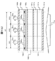
図1(a)および図1(b)は、本発明に関わる液晶表示装置の概略構成の一例を示す模式図である。
図1(a)は、本発明に関わる液晶表示装置の主要部の概略構成の一例を示す模式斜視図である。図1(b)は、図1(a)に示した液晶表示装置の表示原理を示す模式断面図である。
FIG. 1A and FIG. 1B are schematic views showing an example of a schematic configuration of a liquid crystal display device according to the present invention.
FIG. 1A is a schematic perspective view showing an example of a schematic configuration of a main part of a liquid crystal display device according to the present invention. FIG. 1B is a schematic cross-sectional view showing the display principle of the liquid crystal display device shown in FIG.
本発明は、たとえば、液晶テレビなどの透過型の液晶表示装置におけるバックライトの光源として用いる蛍光ランプに適用することができる。透過型の液晶表示装置は、たとえば、図1(a)に示すように、液晶表示パネル1、複数本の蛍光ランプ2、反射部材3、光拡散板4、プリズムシート5、および偏光反射板6を有する。このとき、バックライトは、複数本の蛍光ランプ2、反射部材3、光拡散板4、プリズムシート5、および偏光反射板6を有する面状照明装置であり、図示していないインバータ回路基板により蛍光ランプ2の点灯、消灯を制御する。
The present invention can be applied to, for example, a fluorescent lamp used as a light source of a backlight in a transmissive liquid crystal display device such as a liquid crystal television. As shown in FIG. 1A, for example, the transmissive liquid crystal display device includes a liquid
液晶表示パネル1は、たとえば、図1(b)に示すように、TFT基板101および対向基板102の一対の基板の間に液晶材料103を封入した表示パネルである。
The liquid
TFT基板101は、ガラス基板などの絶縁基板101aの対向基板102と対向する面の上に、走査信号線、映像信号線、TFT素子、画素電極などを有する回路層101bおよび配向膜101cが形成されている。またこのとき、絶縁基板101aの、回路層101bが設けられた面の裏面には、偏光板101dが張り合わされている。
In the
対向基板102は、ガラス基板などの絶縁基板102aのTFT基板101と対向する面の上に、ブラックマトリクスと呼ばれる遮光膜(図示しない)、カラーフィルタ102bR,102bG,102bB、オーバーコート層(図示しない)、配向膜102cが形成されている。またこのとき、絶縁基板102aの、カラーフィルタ102bR,102bG,102bBなどが設けられた面の裏面には、偏光板102dが張り合わされている。
The
液晶表示パネル1の表示領域は、複数の画素の集合で構成されており、たとえば、前記走査信号線の延在方向には、図1(b)に示したように、赤色のカラーフィルタ102bRを有する第1の画素PX1、緑色のカラーフィルタ102bGを有する第2の画素PX2、青色のカラーフィルタ102bBを有する第3の画素PX3が、この順番で並んでいる。このとき、第1の画素PX1、第2の画素PX2、および第3の画素PX3は、一般に、サブ画素と呼ばれており、映像または画像の1ドットDTは、当該3つのサブ画素PX1,PX2,PX3からなる。
The display area of the liquid
第1の画素PX1、第2の画素PX2、および第3の画素PX3は、それぞれ、画素電極と対向電極との電位差によって液晶材料103に印加する電界の大きさを制御することで、液晶材料103の液晶分子の向きを制御する。そして、蛍光ランプ2から光拡散板4、プリズムシート5、および偏光反射板6を介して液晶表示パネル1に入射した白色光VLWは、それぞれの画素における液晶分子の向きに応じた透過率で液晶表示パネル1を透過し、観察者側に出射する。
The first pixel PX1, the second pixel PX2, and the third pixel PX3 each control the magnitude of the electric field applied to the
また、第1の画素PX1のカラーフィルタ102bRは、入射した白色光VLWのうちの赤色の成分の光VLRのみが透過するフィルタである。同様に、第2の画素PX2のカラーフィルタ102bGおよび第3の画素PX3のカラーフィルタ102bBは、それぞれ、入射した白色光VLWのうちの緑色の成分の光VLGのみ、および青色の成分の光VLBのみが透過するフィルタである。そのため、第1の画素PX1における液晶材料103の光透過率、第2の画素PX2における液晶材料103の光透過率、および第3の画素PX3における液晶材料103の光透過率の組み合わせを変えることで、それぞれの画素PX1,PX2,PX3から出射する光VLR,VLG,VLBの強度の組み合わせが変わり、当該3つの画素からなる1ドットDTの色を変えることができる。
The
透過型の液晶表示装置は、上記のように、第1の画素PX1、第2の画素PX2、および第3の画素PX3のそれぞれにおける光VLWの透過率を制御することで、それぞれの画素PX1,PX2,PX3から出射する光VLR,VLG,VLBの強度を制御し、映像や画像を可視化する表示装置である。 The transmission type liquid crystal display device, as described above, the first pixel PX1, by controlling the transmittance of light VL W in each of the second pixel PX2, and a third pixel PX3, each pixel PX1 , PX2, PX3 is a display device that controls the intensity of the light VL R , VL G , VL B and visualizes images and images.
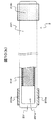
図2(a)乃至図2(d)は、液晶表示装置に用いられる従来の蛍光ランプの概略構成の一例を示す模式図である。
図2(a)は、冷陰極蛍光管の外観および内部構成の一例を示す模式図である。図2(b)は、図2(a)のA−A’線における断面構成の一例を示す模式断面図である。図2(c)は、蛍光膜の厚さ方向の定義を示す模式断面図である。図2(d)は、従来の冷陰極蛍光管における蛍光体の混合比率の一例を示す模式グラフ図である。
なお、図2(c)は、図2(b)の領域PA1を拡大して示した模式断面図である。
また、図2(a)乃至図2(c)では、密閉容器201の断面部分のハッチングを省略している。また、図2(b)および図2(c)では、蛍光膜202の断面部分のハッチングも省略している。
2A to 2D are schematic views showing an example of a schematic configuration of a conventional fluorescent lamp used in a liquid crystal display device.
FIG. 2A is a schematic diagram showing an example of the appearance and internal configuration of a cold cathode fluorescent tube. FIG. 2B is a schematic cross-sectional view showing an example of a cross-sectional configuration along the line AA ′ in FIG. FIG. 2C is a schematic cross-sectional view showing the definition in the thickness direction of the fluorescent film. FIG. 2 (d) is a schematic graph showing an example of the mixing ratio of phosphors in a conventional cold cathode fluorescent tube.
FIG. 2C is a schematic cross-sectional view showing the area PA1 in FIG. 2B in an enlarged manner.
Further, in FIGS. 2A to 2C, the cross-sectional portion of the sealed
液晶表示装置のバックライトの蛍光ランプ2には、たとえば、冷陰極蛍光管(CCFL)が用いられる。冷陰極蛍光管は、たとえば、図2(a)および図2(b)に示すように、透明な密閉容器201、蛍光膜202、一対の電極203a、203b、および密閉容器201の内部空間201aに密封された放電媒体(図示しない)を有する。放電媒体は、蛍光膜202を発光させるための紫外線を放射する媒体であり、たとえば、水銀(Hg)と、アルゴン(Ar)またはネオン(Ne)などの希ガスからなる。
For example, a cold cathode fluorescent tube (CCFL) is used for the
液晶表示装置のバックライトに用いられる冷陰極蛍光管において、密閉容器201は、内径Hが数mm(たとえば、3mm)のガラス管の両端を封止した容器であり、当該ガラス管の内壁には、たとえば、膜厚が15μmから25μm程度の蛍光膜202が固着している。このとき、蛍光膜202は概略円筒形であり、放電媒体から放射された紫外線の大部分は、蛍光膜202の当該放電媒体と対向する主面S1(いわゆる内周面)から蛍光膜202に入射する。
In a cold cathode fluorescent tube used for a backlight of a liquid crystal display device, a sealed
冷陰極蛍光管の蛍光膜202は、発光色が赤色系の赤色蛍光体、発光色が緑色系の緑色蛍光体、および発光色が青色系の青色蛍光体の3種類の蛍光体からなり、放電媒体から放射された紫外線によりそれぞれの蛍光体が励起して可視光を発光する。このとき、赤色蛍光体には、たとえば、Y2O3:Eu3+が用いられる。また、緑色蛍光体には、たとえば、LaPO4:Tb3+,Ce3+が用いられる。また、青色蛍光体には、たとえば、BaMgAl10O17:Eu2+が用いられる。なお、上記の化学式は、蛍光体の通例表記であり、「:」より前方は母体材料の組成を、後方は発光中心を示しており、母体材料の一部の原子を発光中心の原子で置換していることを意味する。
The
また、従来の冷陰極蛍光管の蛍光膜202は、赤色蛍光体、緑色蛍光体、および青色蛍光体を所定の比率で混合した材料を用いて形成される1つの膜であり、当該蛍光膜202を厚さ方向に沿ってみたときの赤色蛍光体、緑色蛍光体、および青色蛍光体の混合比率は、厚さ方向の位置によらず一定の比率になっている。なお、蛍光膜202の厚さ方向は、図2(c)に示すように、ガラス管(密閉容器201)の径方向rであり、蛍光膜202の主面S1からその裏面S2に向かう方向であるとする。このとき、蛍光膜202の主面S1は、放電媒体と対向する面であり、放電媒体から放射された紫外線が入射する面であることは前述の通りである。
The
すなわち、従来の冷陰極蛍光管の蛍光膜202を厚さ方向(r方向)に沿って見たときの赤色蛍光体、緑色蛍光体、および青色蛍光体の混合比率は、たとえば、図2(d)に示すような分布になる。なお、図2(d)に示したグラフ図において、横軸は、蛍光膜202の主面S1からの距離d(単位はμm)であり、主面S1をd=0、裏面S2をd=DMにしている。また、図2(d)に示したグラフ図において、縦軸は混合比率FPであり、3種類の蛍光体の混合比率の和を1にしている。
That is, when the
また、図2(d)に示したグラフ図において、実線は第1の蛍光体F1の混合比率の分布であり、破線は第2の蛍光体F2の混合比率の分布であり、点線は第3の蛍光体F3の混合比率の分布である。第1の蛍光体F1、第2の蛍光体F2、および第3の蛍光体F3は、それぞれ、赤色蛍光体、緑色蛍光体、および青色蛍光体のいずれかである。すなわち、第1の蛍光体F1が赤色蛍光体である場合、第2の蛍光体F2および第3の蛍光体F3は、どちらか一方が緑色蛍光体であり、他方が青色蛍光体である。また、第1の蛍光体F1が緑色蛍光体である場合、第2の蛍光体F2および第3の蛍光体F3は、どちらか一方が赤色蛍光体であり、他方が青色蛍光体である。また、第1の蛍光体F1が青色蛍光体である場合、第2の蛍光体F2および第3の蛍光体F3は、どちらか一方が赤色蛍光体であり、他方が緑色蛍光体である。 In the graph shown in FIG. 2D, the solid line is the distribution of the mixing ratio of the first phosphor F1, the broken line is the distribution of the mixing ratio of the second phosphor F2, and the dotted line is the third. It is distribution of the mixing ratio of phosphor F3. The first phosphor F1, the second phosphor F2, and the third phosphor F3 are any of a red phosphor, a green phosphor, and a blue phosphor, respectively. That is, when the first phosphor F1 is a red phosphor, one of the second phosphor F2 and the third phosphor F3 is a green phosphor and the other is a blue phosphor. When the first phosphor F1 is a green phosphor, one of the second phosphor F2 and the third phosphor F3 is a red phosphor and the other is a blue phosphor. Further, when the first phosphor F1 is a blue phosphor, one of the second phosphor F2 and the third phosphor F3 is a red phosphor and the other is a green phosphor.
このように、従来の冷陰極蛍光管の蛍光膜202は、厚さ方向(r方向)に沿ってみたときの赤色蛍光体、緑色蛍光体、および青色蛍光体の混合比率は、厚さ方向の位置、すなわち主面S1からの距離dによらず一定の比率になっている。
Thus, the
なお、蛍光膜202における第1の蛍光体F1、第2の蛍光体F2、および第3の蛍光体F3の組み合わせおよび混合比率は、冷陰極蛍光管から発する光に要求される白色色度によって適宜変更される。しかしながら、従来の冷陰極蛍光管(蛍光ランプ2)における蛍光膜202は、当該蛍光膜202を厚さ方向に沿ってみたときの赤色蛍光体、緑色蛍光体、および青色蛍光体の混合比率が、厚さ方向の位置によらず一定の比率になっている。
Note that the combination and mixing ratio of the first phosphor F1, the second phosphor F2, and the third phosphor F3 in the
これに対し、本発明の蛍光ランプ2は、蛍光膜202を厚さ方向rに沿ってみたときの赤色蛍光体、緑色蛍光体、および青色蛍光体の混合比率が、以下で説明する条件にしたがう分布になるようにすることで、蛍光ランプ2の高効率化、高輝度化を実現する。
On the other hand, in the
図3乃至図5は、本発明による蛍光ランプの蛍光膜における蛍光体の混合比率の条件を説明するための模式図である。
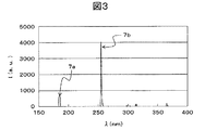
図3は、低圧水銀ランプにおける水銀の放出スペクトルの一例を示す模式グラフ図である。図4は、低圧水銀ランプにおけるガラス管の内径と紫外線の強度比率との関係の一例を示す模式グラフ図である。図5は、蛍光膜が有する蛍光体の励起スペクトルの一例を示す模式グラフ図である。
FIG. 3 to FIG. 5 are schematic diagrams for explaining the condition of the mixing ratio of the phosphors in the fluorescent film of the fluorescent lamp according to the present invention.
FIG. 3 is a schematic graph showing an example of a mercury emission spectrum in a low-pressure mercury lamp. FIG. 4 is a schematic graph showing an example of the relationship between the inner diameter of a glass tube and the intensity ratio of ultraviolet rays in a low-pressure mercury lamp. FIG. 5 is a schematic graph showing an example of an excitation spectrum of a phosphor included in the phosphor film.
液晶表示装置のバックライトの蛍光ランプ2(冷陰極蛍光管)には、一般に、低圧水銀ランプが用いられる。低圧水銀ランプは、一対の電極203a,203bの間に高周波電圧を印加したときに電極203a,203bから放出される電子により水銀を励起し、励起した水銀が基底状態に戻る際に放出される紫外線で蛍光膜202の蛍光体を励起して可視光を発光する。このとき、水銀から放射される紫外線は、主に、ピーク波長が254nmの紫外線である。
A low-pressure mercury lamp is generally used for the fluorescent lamp 2 (cold cathode fluorescent tube) of the backlight of the liquid crystal display device. The low-pressure mercury lamp excites mercury by electrons emitted from the
しかしながら、液晶表示装置のバックライトの冷陰極蛍光管のようにガラス管(密閉容器201)の内径Hが非常に小さい低圧水銀ランプの場合、水銀の放出スペクトルは、たとえば、図3に示すような分布になる。なお、図3に示したグラフ図において、横軸は紫外線領域の光の波長λ(単位はnm)であり、縦軸は強度I(単位は任意)である。 However, in the case of a low-pressure mercury lamp in which the inner diameter H of the glass tube (sealed container 201) is very small, such as a cold cathode fluorescent tube of a backlight of a liquid crystal display device, the mercury emission spectrum is as shown in FIG. Distribution. In the graph shown in FIG. 3, the horizontal axis represents the wavelength λ (unit: nm) of light in the ultraviolet region, and the vertical axis represents intensity I (unit: arbitrary).
このとき、水銀から放射される紫外線のうちの、蛍光膜202の発光への寄与が大きい紫外線は、ピーク波長が185nmの第1の紫外線7aと、ピーク波長が254nmの第2の紫外線7bである。なお、水銀から放射される紫外線には、図3に示したように、第1の紫外線7aおよび第2の紫外線7bよりもピーク波長が長い紫外線も含まれるが、それらの紫外線の強度は、第1の紫外線7aおよび第2の紫外線7bの強度に比べて非常に小さく、蛍光膜202の発光への寄与が非常に小さいといえる。そのため、水銀から放射される紫外線は、主として、ピーク波長が185nmの第1の紫外線7aおよびピーク波長が254nmの第2の紫外線7bの2種類の紫外線からなると見なすことができる。
At this time, of the ultraviolet rays radiated from mercury, the ultraviolet rays having a large contribution to the light emission of the
またこのとき、第1の紫外線7aの強度と第2の紫外線7bの強度との比率は、ガラス管の内径Hの大きさに強く依存しており、その関係は、たとえば、図4に示すような関係になる。なお、図4に示したグラフ図において、横軸はガラス管の内径H(単位はmm)であり、縦軸は第1の紫外線7aの強度を第2の紫外線7bの強度で除した値を百分率で示した強度比率IR(単位は%)である。
At this time, the ratio between the intensity of the first ultraviolet ray 7a and the intensity of the second
このように、放電媒体として水銀を利用する冷陰極蛍光管(低圧水銀ランプ)は、ガラス管の内径Hが小さくなるにしたがい、水銀から放射される第1の紫外線7aと第2の紫外線7bとの強度比率IRが大きくなる。また、ガラス管の内径Hを小さくすると、第1の紫外線7aは、たとえば、水銀に自己吸収される前に蛍光膜202の主面S1まで到達し、蛍光膜202に入射する量が増えると考えられる。
As described above, the cold cathode fluorescent tube (low pressure mercury lamp) using mercury as a discharge medium has the first ultraviolet ray 7a and the second
したがって、液晶表示装置のバックライトの蛍光ランプ2(冷陰極蛍光管)では、蛍光膜202から可視光を発光させる紫外線として、ピーク波長が185nmの第1の紫外線7aと、ピーク波長が254nmの第2の紫外線7bの両方を考慮する必要がある。
Therefore, in the fluorescent lamp 2 (cold cathode fluorescent tube) as the backlight of the liquid crystal display device, the first ultraviolet ray 7a having a peak wavelength of 185 nm and the first ultraviolet ray having a peak wavelength of 254 nm are used as ultraviolet rays for emitting visible light from the
ところで、第2の紫外線7bのように波長が比較的長い紫外線は、蛍光膜202の主面S1から蛍光膜202に入射したときに、蛍光膜202の深い部分(裏面S2の近傍)まで到達することができ、浅い部分(主面S1の近傍)の蛍光体から深い部分の蛍光体まで発光させることができる。これに対し、第1の紫外線7aのように波長が短い紫外線は、蛍光膜202の主面S1から蛍光膜202に入射したときに、蛍光膜202の浅い部分で吸収されやすく、浅い部分の蛍光体しか発光させることができない。これは、短波長の紫外線(特に、波長が200nm未満の真空紫外線)が、蛍光膜202の隙間に存在する放電媒体などに吸収されやすいからである。
By the way, ultraviolet rays having a relatively long wavelength such as the second
したがって、液晶表示装置のバックライトに用いられる蛍光ランプ2は、第1の紫外線7aによる蛍光体の発光効率を高くすることで、蛍光ランプ2の高効率化、高輝度化ができると考えられる。
Therefore, it is considered that the
第1の紫外線7aによる蛍光体の発光効率を高くするには、たとえば、第2の紫外線7bで励起するよりも、第1の紫外線7aで励起するほうが発光強度が高い蛍光体を、蛍光膜202の主面S1の近傍に多く配置すればよい。
In order to increase the luminous efficiency of the phosphor by the first ultraviolet ray 7a, for example, a phosphor having a higher emission intensity when excited with the first ultraviolet ray 7a than with the second
蛍光膜202において、赤色蛍光体、緑色蛍光体、および青色蛍光体が、それぞれ、Y2O3:Eu3+、LaPO4:Tb3+,Ce3+、およびBaMgAl10O17:Eu2+である場合、それぞれの蛍光体の励起スペクトルを調べると、たとえば、図5に示すような分布になる。なお、図5に示したグラフ図において、横軸は蛍光体に照射する紫外線の波長λ(単位はnm)であり、縦軸は蛍光体から放射される可視光の発光強度Iの相対値である。また、図5に示したグラフ図において、点線は赤色蛍光体Faから放射される可視光の発光強度の分布であり、太い破線は緑色蛍光体Fbから放射される可視光の発光強度の分布であり、実線は青色蛍光体Fcから放射される可視光の発光強度の分布である。また、図5のグラフ図では、第2の紫外線7bのピーク波長である波長254nmの紫外線を照射したときにそれぞれの蛍光体Fa,Fb,Fcから放射される可視光の発光強度を1に揃えて示している。
In the
このように、それぞれの蛍光体Fa,Fb,Fcは、励起スペクトルの分布、すなわち蛍光体を励起させる紫外線の波長λと蛍光体から放射される可視光の発光強度Iとの関係が大きく異なる。 As described above, the phosphors Fa, Fb, and Fc are greatly different from each other in the excitation spectrum distribution, that is, the relationship between the wavelength λ of the ultraviolet light that excites the phosphor and the emission intensity I of the visible light emitted from the phosphor.
赤色蛍光体がY2O3:Eu3+の場合、波長254nmの紫外線を照射したときに放射される可視光の発光強度Iを1とすると、第1の紫外線7aのピーク波長である波長185nmの紫外線を照射したときに放射される可視光の発光強度Iは、およそ0.88である。 When the red phosphor is Y 2 O 3 : Eu 3+ , assuming that the emission intensity I of visible light emitted when irradiating ultraviolet rays with a wavelength of 254 nm is 1, the peak wavelength of the first ultraviolet ray 7a is 185 nm. The emission intensity I of visible light emitted when irradiated with ultraviolet rays is approximately 0.88.
また、緑色蛍光体がLaPO4:Tb3+,Ce3+の場合、波長254nmの紫外線を照射したときに放射される可視光の発光強度Iを1とすると、第1の紫外線7aのピーク波長である波長185nmの紫外線を照射したときに放射される可視光の発光強度Iは、およそ1.04である。 Further, when the green phosphor is LaPO 4 : Tb 3+ , Ce 3+ , the peak wavelength of the first ultraviolet ray 7a is assumed when the emission intensity I of visible light emitted when the ultraviolet ray having a wavelength of 254 nm is irradiated is 1. The emission intensity I of visible light emitted when irradiated with ultraviolet rays having a wavelength of 185 nm is approximately 1.04.
また、青色蛍光体FaがBaMgAl10O17:Eu2+の場合、波長254nmの紫外線を照射したときに放射される可視光の発光強度Iを1とすると、第1の紫外線7aのピーク波長である波長185nmの紫外線を照射したときに放射される可視光の発光強度Iは、およそ1.11である。 Further, when the blue phosphor Fa is BaMgAl 10 O 17 : Eu 2+ , the peak wavelength of the first ultraviolet ray 7a is assumed when the emission intensity I of visible light emitted when irradiating the ultraviolet ray having a wavelength of 254 nm is 1. The emission intensity I of visible light emitted when irradiated with ultraviolet rays having a wavelength of 185 nm is approximately 1.11.
すなわち、赤色蛍光体、緑色蛍光体、および青色蛍光体の組み合わせが、上記の化学式で表される材料の組み合わせの場合、第2の紫外線7bで励起するよりも、第1の紫外線7aで励起するほうが発光強度が高い蛍光体は、緑色蛍光体Fbおよび青色蛍光体Fcである。また、緑色蛍光体Fbおよび青色蛍光体Fcのうち、第2の紫外線7bで励起したときの発光強度に対する第1の紫外線7aで励起したときの発光強度の比率が大きいのは、青色蛍光体Fcである。したがって、蛍光ランプ2を高効率化、高輝度化するには、たとえば、蛍光膜202の浅い部分(主面S1の近傍)に青色蛍光体Fcを多く配置すればよいと考えられる。
That is, when the combination of the red phosphor, the green phosphor, and the blue phosphor is a combination of materials represented by the above chemical formula, it is excited by the first ultraviolet ray 7a rather than being excited by the second
なお、図5に示した蛍光体の励起スペクトルは、赤色蛍光体Fa、緑色蛍光体Fb、および青色蛍光体Fcが、それぞれ、上記の化学式で表される材料の場合の励起スペクトルの一例である。すなわち、赤色蛍光体Fa、緑色蛍光体Fb、および青色蛍光体Fcとして用いる材料が、それぞれ、上記の化学式で表される材料とは異なる場合、励起スペクトルは異なる分布になる。そのため、波長254nmの紫外線による可視光の発光強度Iを1としたときの、波長185nmの紫外線による可視光の発光強度Iの大きさも変わる。 The excitation spectrum of the phosphor shown in FIG. 5 is an example of the excitation spectrum in the case where the red phosphor Fa, the green phosphor Fb, and the blue phosphor Fc are materials represented by the above chemical formulas, respectively. . That is, when the materials used as the red phosphor Fa, the green phosphor Fb, and the blue phosphor Fc are different from the materials represented by the above chemical formulas, the excitation spectra have different distributions. Therefore, when the visible light emission intensity I due to ultraviolet light having a wavelength of 254 nm is 1, the magnitude of the visible light emission intensity I due to ultraviolet light having a wavelength of 185 nm also changes.
以上のことから、液晶表示装置のバックライトに用いる蛍光ランプ2は、蛍光膜202を厚さ方向で見たときの赤色蛍光体、緑色蛍光体、および青色蛍光体の混合比率を変動させることが望ましいといえる。すなわち、本発明の蛍光ランプ2は、蛍光膜202を厚さ方向で見たときの赤色蛍光体、緑色蛍光体、および青色蛍光体の混合比率が変動していることを最も主要な特徴とする。
From the above, the
このとき、蛍光膜202の構成は、たとえば、厚さ方向で見たときに、赤色蛍光体の混合比率が最も高い第1の部分、緑色蛍光体の混合比率が最も高い第2の部分、および青色蛍光体の混合比率が最も高い部分が存在するような構成にする。このとき、第1の部分、第2の部分、および第3の部分は、蛍光膜202の厚さ方向に対して、下記式1で表される可視光強度比IRa,IRb,IRcが大きい順に存在するような構成にすることが望ましい。
At this time, the configuration of the
なお、上記式1において、IRa、IRb、およびIRcは、それぞれ、赤色蛍光体Fa、緑色蛍光体Fb、および青色蛍光体Fcの可視光強度比である。また、上記式1において、λ1は第1の紫外線7aのピーク波長であり、λ2は第2の紫外線7bのピーク波長である。また、上記式1において、Ia(λ1)、Ib(λ1)、およびIc(λ1)は、それぞれ、赤色蛍光体Fa、緑色蛍光体Fb、および青色蛍光体Fcを波長λ1の紫外線(第1の紫外線7a)で励起したときの可視光強度である。また、上記式1において、Ia(λ2)、Ib(λ2)、およびIc(λ2)は、それぞれ、赤色蛍光体Fa、緑色蛍光体Fb、および青色蛍光体Fcを波長λ2の紫外線(第2の紫外線7b)で励起したときの可視光強度である。
In
赤色蛍光体Fa、緑色蛍光体Fb、および青色蛍光体Fcが、上記の化学式で表される材料の組み合わせである場合、それぞれの蛍光体Fa,Fb,Fcの励起スペクトルは、図5に示したような分布になる。このとき、赤色蛍光体Faの可視光強度比IRa、緑色蛍光体Fbの可視光強度比IRb、および青色蛍光体Fcの可視光強度比IRcは、図5および上記式1から、それぞれ、0.88、1.04、および1.11である。すなわち、赤色蛍光体Faの可視光強度比IRa、緑色蛍光体Fbの可視光強度比IRb、および青色蛍光体Fcの可視光強度比IRcの関係は、IRc>IRb>IRaの関係である。したがって、赤色蛍光体Fa、緑色蛍光体Fb、および青色蛍光体Fcが、上記の化学式で表される材料の組み合わせである場合、蛍光膜202は、厚さ方向で見たときに、青色蛍光体Fcの混合比率が最も高い第3の部分、緑色蛍光体Fbの混合比率が最も高い第2の部分、赤色蛍光体Faの混合比率が最も高い第1の部分の順に存在するような構成にする。
When the red phosphor Fa, the green phosphor Fb, and the blue phosphor Fc are a combination of materials represented by the above chemical formula, the excitation spectra of the respective phosphors Fa, Fb, Fc are shown in FIG. It becomes distribution like this. At this time, the visible light intensity ratio IRa of the red phosphor Fa, the visible light intensity ratio IRb of the green phosphor Fb, and the visible light intensity ratio IRc of the blue phosphor Fc are 0. 88, 1.04, and 1.11. That is, the relationship between the visible light intensity ratio IRa of the red phosphor Fa, the visible light intensity ratio IRb of the green phosphor Fb, and the visible light intensity ratio IRc of the blue phosphor Fc is IRc> IRb> IRa. Therefore, when the red phosphor Fa, the green phosphor Fb, and the blue phosphor Fc are a combination of materials represented by the above chemical formula, the
またこのとき、蛍光膜202は、たとえば、緑色蛍光体Fbと青色蛍光体Fcとを所定の割合で混合した複合蛍光体と、赤色蛍光体Faとの混合体とし、厚さ方向で見たときに、主面S1の近傍では複合蛍光体の混合比率のほうが高くなり、裏面S2の近傍では赤色蛍光体Faの混合比率のほうが高くなるような構成にしてもよい。
At this time, the
このように、本発明の蛍光ランプ2は、蛍光膜202を厚さ方向で見たときの赤色蛍光体Fa、緑色蛍光体Fb、および青色蛍光体Fcの混合比率を変動させることで、第1の紫外線7aによる発光効率を向上させ、蛍光ランプ2の高効率化、高輝度化を実現する。
As described above, the
ところで、蛍光ランプ2の輝度は、一般に、緑色蛍光体Fbの発光強度で決まることが知られている。そのため、蛍光ランプ2は、放電媒体(水銀)から放射される紫外線により緑色蛍光体Fbから放射される緑色の可視光の光量を多くすることで、蛍光ランプ2としての輝度や発光効率は高くなる。
Incidentally, it is known that the luminance of the
したがって、本発明の蛍光ランプ2は、蛍光膜202の構成を、たとえば、主面S1の近傍に緑色蛍光体Fbが多く配置される構成にしてもよい。このようにすると、蛍光膜202の主面S1の近傍では、第1の紫外線7aおよび第2の紫外線7bの両方により緑色蛍光体Fbから緑色の可視光を放射させることができる。そのため、このような構成の蛍光ランプ2は、緑色蛍光体Fbの発光効率を向上させることができ、蛍光ランプ2としての輝度や発光効率を高くすることができる。
Therefore, in the
なお、蛍光膜202の主面S1の近傍に緑色蛍光体Fbが多く配置する構成の場合、当該蛍光膜202を厚さ方向で見たときの第1の部分、第2の部分、および第3の部分の順番は、式1で表される可視光強度比IRa,IRb,IRcが大きい順にはならないことがある。しかしながら、蛍光膜202の主面S1の近傍に緑色蛍光体Fbを多く配置すれば、蛍光膜202を厚さ方向で見たときの赤色蛍光体Fa、緑色蛍光体Fb、および青色蛍光体Fcの混合比率が変動し、本発明の蛍光ランプ2の最も主要な特徴を有する構成になることはもちろんである。
In the case where the green phosphor Fb is arranged in the vicinity of the main surface S1 of the
図6は、本発明による実施例1の蛍光ランプにおける蛍光体の混合比率の一例を示す模式グラフ図である。
なお、図6に示したグラフ図において、横軸は、蛍光膜202の主面S1からの距離d(単位はμm)であり、主面S1をd=0、裏面S2をd=DMとしている。また、図6に示したグラフ図において、縦軸は混合比率FPである。また、図6に示したグラフ図において、実線は青色蛍光体Fcの混合比率の分布であり、太い破線は緑色蛍光体Fbの混合比率の分布であり、点線は赤色蛍光体Faの混合比率の分布である。
FIG. 6 is a schematic graph showing an example of the mixing ratio of phosphors in the fluorescent lamp of Example 1 according to the present invention.
Note that in the graph shown in FIG. 6, the horizontal axis represents a distance d from the main surface S1 of the fluorescent film 202 (in [mu] m) is, the main surface S1 d = 0 and the back surface S2 as d = D M Yes. In the graph shown in FIG. 6, the vertical axis represents the mixing ratio FP. In the graph shown in FIG. 6, the solid line is the distribution of the mixing ratio of the blue phosphor Fc, the thick broken line is the distribution of the mixing ratio of the green phosphor Fb, and the dotted line is the mixing ratio of the red phosphor Fa. Distribution.
実施例1では、蛍光ランプ2の一例として、図2(a)および図2(b)に示したような構成の冷陰極蛍光管を挙げる。このとき、実施例1の冷陰極蛍光管は、外観上は従来の冷陰極蛍光管と概ね同じであり、蛍光膜202の構成のみが異なる。またこのとき、蛍光膜202は、赤色蛍光体Fa、緑色蛍光体Fb、および青色蛍光体Fcからなり、それぞれ、Y2O3:Eu3+、LaPO4:Tb3+,Ce3+、およびBaMgAl10O17:Eu2+であるとする。
In the first embodiment, as an example of the
実施例1の冷陰極蛍光管の蛍光膜202は、厚さ方向で見たときの、赤色蛍光体Fa、緑色蛍光体Fb、および青色蛍光体Fcのそれぞれの混合比率の分布が、たとえば、図6に示したような分布になるようにする。なお、蛍光膜202の厚さ方向は、蛍光膜202の主面S1(内周面)から裏面S2(外周面)に向かう方向である。
When the
すなわち、実施例1の冷陰極蛍光管の蛍光膜202は、たとえば、厚さ方向で見たときに、青色蛍光体Fcの混合比率が最も高い第3の部分、緑色蛍光体Fbの混合比率が最も高い第2の部分、赤色蛍光体Faの混合比率が最も高い第1の部分の順に存在する。
That is, the
このとき、青色蛍光体Fcの混合比率FPは、蛍光膜202の主面S1およびその近傍における混合比率FPが最大(FP=1)になり、主面S1から遠ざかるにしたがい徐々に混合比率FPが小さくなるように変動する。またこのとき、青色蛍光体Fcの混合比率FPは、たとえば、蛍光膜202の0.5DM<d≦DMの部分では混合比率FPが0になるように変動する。
At this time, the mixing ratio FP of the blue phosphor Fc is such that the mixing ratio FP at the main surface S1 of the
また、赤色蛍光体Faの混合比率FPは、蛍光膜202の主面S1から厚さ方向の中心(d=0.5DM)までの0≦d<0.5DMの部分で混合比率FPが0になり、蛍光膜202の0.5DM<d≦DMの部分では混合比率FPが徐々に大きくなるように変動する。またこのとき、赤色蛍光体Faの混合比率FPは、蛍光膜202の裏面S2およびその近傍における混合比率FPが最大(FP=1)になるように変動する。
Further, the mixing ratio FP of the red phosphor Fa is such that the mixing ratio FP is 0 ≦ d <0.5D M from the main surface S1 of the
また、緑色蛍光体Fbの混合比率FPは、蛍光膜202の厚さ方向の中心で極大(FP=1)になるように変動する。
Further, the mixing ratio FP of the green phosphor Fb varies so as to become a maximum (FP = 1) at the center of the
このような構成の蛍光膜202において、赤色蛍光体Fa、緑色蛍光体Fb、および青色蛍光体Fcが、それぞれ、Y2O3:Eu3+、LaPO4:Tb3+,Ce3+、およびBaMgAl10O17:Eu2+であれば、それぞれの蛍光体の励起スペクトルは、図5に示したような分布になる。そのため、上記式1から求まる可視光強度比IRa,IRb,IRcの関係は、IRc>IRb>IRaになる。したがって、実施例1の蛍光ランプ202は、ピーク波長が短い第1の紫外線7aによる蛍光膜202の発光効率を向上させることができる。このとき、実施例1の蛍光ランプ2は、たとえば、それぞれの蛍光体Fa,Fb,Fcの混合比率FPの分布が図2(d)に示したような均一な分布である従来の蛍光ランプ2と比べて、使用する各蛍光体の量や、電極203a,203bの間に印加する電圧の大きさなどを変えることなく、発光効率を約1.03倍に向上させることができる。そのため、実施例1の蛍光ランプ2を液晶表示装置のバックライトの光源として用いることで、液晶表示装置の高輝度化(高画質化)、低コスト化、さらには薄型化が可能になる。
In the
実施例1の冷陰極蛍光管(蛍光ランプ2)は、蛍光膜202を厚さ方向で見たときに、青色蛍光体Fcの混合比率が最も高い第3の部分、緑色蛍光体Fbの混合比率が最も高い第2の部分、赤色蛍光体Faの混合比率が最も高い第1の部分の順に存在することが最も主要な特徴である。そのため、蛍光膜202を厚さ方向で見たときのそれぞれの蛍光体の混合比率は、上記の特徴を有する範囲内で、適宜変更可能なことはもちろんである。
In the cold cathode fluorescent tube (fluorescent lamp 2) of Example 1, when the
したがって、蛍光膜202を厚さ方向で見たときのそれぞれの蛍光体Fa,Fb,Fcの混合比率FPの分布は、たとえば、蛍光膜202の膜厚方向の中心(d=0.5DM)に、緑色蛍光体Fb、青色蛍光体Fc、および赤色蛍光体Faの3つの蛍光体が混合している部分がある程度の幅をもって存在してもよい。
Accordingly, the distribution of the mixing ratio FP of the respective phosphors Fa, Fb, Fc when the
またさらに、蛍光膜202を厚さ方向で見たときのそれぞれの蛍光体Fa,Fb,Fcの混合比率FPの分布は、たとえば、蛍光膜202の膜厚方向の中心(d=0.5DM)およびその近傍に、緑色蛍光体Fbのみからなる部分がある程度の幅をもって存在してもよい。
Furthermore, the distribution of the mixing ratio FP of the respective phosphors Fa, Fb, Fc when the
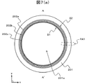
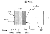
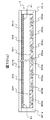
図7(a)乃至図7(c)は、本発明による実施例2の蛍光ランプの概略構成の一例を示す模式図である。
図7(a)は、本発明による実施例2の蛍光ランプの断面構成の一例を示す模式断面図である。図7(b)は、図7(a)の領域PA2を拡大して示した模式断面図である。図7(c)は、実施例2の蛍光ランプにおける蛍光体の混合比率の一例を示す模式グラフ図である。
なお、図7(a)は、図2(a)のA−A’線における断面構成に相当する模式断面図である。
また、図7(c)に示したグラフ図において、横軸は、蛍光膜202の主面S1からの距離d(単位はμm)であり、主面S1をd=0、裏面S2をd=DMとしている。また、図7(c)に示したグラフ図において、縦軸は混合比率FPである。また、図7(c)に示したグラフ図において、実線は青色蛍光体Fcの混合比率の分布であり、太い破線は緑色蛍光体Fbの混合比率の分布であり、点線は赤色蛍光体Faの混合比率の分布である。
FIG. 7A to FIG. 7C are schematic views showing an example of a schematic configuration of the fluorescent lamp of Example 2 according to the present invention.
Fig.7 (a) is a schematic cross section which shows an example of a cross-sectional structure of the fluorescent lamp of Example 2 by this invention. FIG. 7B is a schematic cross-sectional view showing the area PA2 in FIG. FIG. 7C is a schematic graph showing an example of the mixing ratio of phosphors in the fluorescent lamp of Example 2.
FIG. 7A is a schematic cross-sectional view corresponding to the cross-sectional configuration taken along the line AA ′ of FIG.
In the graph shown in FIG. 7C, the horizontal axis is the distance d (unit: μm) from the main surface S1 of the
実施例2では、蛍光ランプ2の一例として、図2(a)に示したような構成の冷陰極蛍光管を挙げる。このとき、実施例2の冷陰極蛍光管は、外観上は従来の冷陰極蛍光管と概ね同じであり、蛍光膜202の構成のみが異なる。またこのとき、蛍光膜202は、赤色蛍光体Fa、緑色蛍光体Fb、および青色蛍光体Fcからなり、それぞれ、Y2O3:Eu3+、LaPO4:Tb3+,Ce3+、およびBaMgAl10O17:Eu2+であるとする。
In Example 2, as an example of the
実施例2の冷陰極蛍光管の蛍光膜202は、厚さ方向で見たときに、たとえば、図7(a)および図7(b)に示すように、青色蛍光体Fcからなる青色蛍光層202c、緑色蛍光体Fbからなる緑色蛍光層202b、および赤色蛍光体Faからなる赤色蛍光層202aが、この順番で積層した積層膜になっている。なお、蛍光膜202の厚さ方向は、蛍光膜202の主面S1から裏面S2に向かう方向である。
When viewed in the thickness direction, the
このとき、蛍光膜202を厚さ方向で見たときの赤色蛍光体Fa、緑色蛍光体Fb、および青色蛍光体Fcのそれぞれの混合比率の分布は、たとえば、図7(c)に示したような分布になっている。すなわち、蛍光膜202は、厚さ方向で見たときに、青色蛍光体Fcの混合比率が最も高い第3の部分、緑色蛍光体Fbの混合比率が最も高い第2の部分、赤色蛍光体Fcの混合比率が最も高い第1の部分の順に存在する。
At this time, the distribution of the mixing ratios of the red phosphor Fa, the green phosphor Fb, and the blue phosphor Fc when the
このとき、青色蛍光体Fcの混合比率FPは、蛍光膜202の主面S1からの距離dがd=0からd=D1の部分で混合比率FPが最大(FP=1)になり、D1<d≦DMの部分では混合比率FPが0になるように変動する。
In this case, the mixing ratio FP of the blue phosphor Fc is the mixing ratio FP from the distance d is d = 0 from the main surface S1 is part of d = D 1 of the
また、赤色蛍光体Faの混合比率FPは、蛍光膜202の主面S1からの距離dが0≦d<D2の部分では混合比率FPが0になり、D2≦d≦DMでは混合比率FPが0になるように変動する。
The mixing ratio FP of the red phosphor Fa, the mixing ratio FP is the distance d is 0 ≦ d <D 2 parts of the main surface S1 of the
また、緑色蛍光体Fbの混合比率FPは、蛍光膜202の主面S1からの距離dが0≦d≦D1の部分およびD2≦d≦DMの部分では混合比率FPが0になり、D1<d<D2の部分で混合比率FPが最大(FP=1)になるように変動する。
The mixing ratio FP of the green phosphor Fb is the mixing ratio FP becomes 0 at a portion of the
このような構成の蛍光膜202において、赤色蛍光体Fa、緑色蛍光体Fb、および青色蛍光体Fcが、それぞれ、Y2O3:Eu3+、LaPO4:Tb3+,Ce3+、およびBaMgAl10O17:Eu2+であれば、それぞれの蛍光体の励起スペクトルは、図5に示したような分布になる。そのため、上記式1から求まる可視光強度比IRa,IRb,IRcの関係は、IRc>IRb>IRaになる。したがって、実施例2の蛍光ランプ202は、ピーク波長が短い第1の紫外線7aによる蛍光膜202の発光効率を向上させることができる。このとき、実施例2の蛍光ランプ2は、たとえば、それぞれの蛍光体Fa,Fb,Fcの混合比率FPの分布が図2(d)に示したような均一な分布である従来の蛍光ランプ2と比べて、使用する各蛍光体の量や、電極203a,203bの間に印加する電圧の大きさなどを変えることなく、発光効率を約1.03倍に向上させることができる。そのため、実施例2の蛍光ランプ2を液晶表示装置のバックライトの光源として用いることで、液晶表示装置の高輝度化(高画質化)、低コスト化、さらには薄型化が可能になる。
In the
図8は、実施例2の蛍光ランプ2の製造方法の一例を示す模式フロー図である。
FIG. 8 is a schematic flow diagram illustrating an example of a method for manufacturing the
実施例2の冷陰極蛍光管(蛍光ランプ2)は、蛍光膜202を厚さ方向で見たときに、青色蛍光層202c、緑色蛍光層202b、および赤色蛍光層202aの順に存在している。すなわち、実施例2の冷陰極蛍光管(蛍光ランプ2)における蛍光膜202は、ガラス管(密閉容器201)の内壁に、赤色蛍光層202a、緑色蛍光層202b、および青色蛍光層202cの順に積層されている。
In the cold cathode fluorescent tube (fluorescent lamp 2) of Example 2, the
このような構成の冷陰極蛍光管を製造するときには、たとえば、図8に示したような手順で製造する。すなわち、実施例2の冷陰極蛍光管の製造方法では、まず、蛍光体毎にサスペンジョンと呼ばれる混合液を作製する(ステップ801)。ステップ801は、たとえば、ニトロセルロースと酢酸ブチルからなる有機溶剤(一般に、ビークルと呼ばれる。)に、アルミナなどの結着剤、蛍光体材料などを混合して作製する。また、ステップ801では、ビークルに赤色蛍光体(たとえば、Y2O3:Eu3+)を混合した第1のサスペンジョン、ビークルに緑色蛍光体(たとえば、LaPO4:Tb3+,Ce3+)を混合した第2のサスペンジョン、ビークルに青色蛍光体(たとえば、BaMgAl10O17:Eu2+)を混合した第3のサスペンジョンの3種類のサスペンジョンを作製する。
When the cold cathode fluorescent tube having such a configuration is manufactured, for example, it is manufactured according to the procedure shown in FIG. That is, in the manufacturing method of the cold cathode fluorescent tube of Example 2, first, a mixed liquid called a suspension is prepared for each phosphor (step 801). Step 801 is made by, for example, mixing an organic solvent (generally called a vehicle) composed of nitrocellulose and butyl acetate with a binder such as alumina, a phosphor material, and the like. In
次に、密閉容器201として用いるガラス管の内壁に各サスペンジョンを塗布し、乾燥させる(ステップ802)。ステップ802は、たとえば、両端が開口したガラス管の一方の開口端をサスペンジョンに浸し、もう一方の開口端からポンプで吸引してサスペンジョンを引き上げて塗布し、乾燥させる。このとき、ガラス管は、たとえば、管の内径が約3mmのコバールガラスの管を用いる。また、ステップ802は、第1のサスペンジョンの塗布および乾燥、第2のサスペンジョンの塗布および乾燥、第3のサスペンジョンの塗布および乾燥の順に行う。
Next, each suspension is applied to the inner wall of a glass tube used as the sealed
次に、ガラス管の内壁に塗布し、乾燥させた各サスペンジョンをベーキング(焼成)して各蛍光体をガラス管の内壁に固着させる(ステップ803)。このステップ803により、ガラス管の内壁に、赤色蛍光層202a、緑色蛍光層202b、および青色蛍光層202cを積層した蛍光膜202が形成される。
Next, each of the suspensions applied to the inner wall of the glass tube and dried is baked (fired) to fix each phosphor to the inner wall of the glass tube (step 803). By this
次に、ガラス管の両方の開口端に電極203a,203bを取り付け、当該ガラス管の一方の開口端(一端)を封止する(ステップ804)。
Next,
次に、ガラス管のもう一方の開口端から放電媒体を注入する(ステップ805)。ステップ805は、たとえば、アルゴン(Ar)またはネオン(Ne)などの希ガスを注入し、ガス圧を調整した後、水銀を注入する。
Next, a discharge medium is injected from the other open end of the glass tube (step 805). In
次に、ガラス管のもう一方の開口端(他端)を封止する(ステップ806)。 Next, the other open end (the other end) of the glass tube is sealed (step 806).
そして最後に、このガラス管を一定時間点灯させるエージング処理を行う(ステップ807)。 Finally, an aging process is performed for lighting the glass tube for a predetermined time (step 807).
このような手順で製造された実施例2の冷陰極蛍光管は、前述のように、従来の冷陰極蛍光管に比べて、高輝度化、高効率化できる。 As described above, the cold cathode fluorescent tube of Example 2 manufactured by such a procedure can achieve higher brightness and higher efficiency than the conventional cold cathode fluorescent tube.
図9は、本発明による実施例3の蛍光ランプにおける蛍光体の混合比率の一例を示す模式グラフ図である。
なお、図9に示したグラフ図において、横軸は、蛍光膜202の主面S1からの距離d(単位はμm)であり、主面S1をd=0、裏面S2をd=DMとしている。また、図9に示したグラフ図において、縦軸は混合比率FPである。また、図9に示したグラフ図において、実線は青色蛍光体Fcの混合比率の分布であり、太い破線は緑色蛍光体Fbの混合比率の分布であり、点線は赤色蛍光体Faの混合比率の分布であり、一点鎖線は複合蛍光体Fdの混合比率の分布である。
FIG. 9 is a schematic graph showing an example of the mixing ratio of phosphors in the fluorescent lamp of Example 3 according to the present invention.
Note that in the graph shown in FIG. 9, the horizontal axis represents a distance d from the main surface S1 of the fluorescent film 202 (in [mu] m) is, the main surface S1 d = 0 and the back surface S2 as d = D M Yes. In the graph shown in FIG. 9, the vertical axis represents the mixing ratio FP. In the graph shown in FIG. 9, the solid line is the distribution of the mixing ratio of the blue phosphor Fc, the thick broken line is the distribution of the mixing ratio of the green phosphor Fb, and the dotted line is the mixing ratio of the red phosphor Fa. This is the distribution, and the one-dot chain line is the distribution of the mixing ratio of the composite phosphor Fd.
実施例3では、蛍光ランプ2の一例として、図2(a)および図2(b)に示したような構成の冷陰極蛍光管を挙げる。このとき、実施例3の冷陰極蛍光管は、外観上は従来の冷陰極蛍光管と概ね同じであり、蛍光膜202の構成のみが異なる。またこのとき、蛍光膜202は、赤色蛍光体Fa、緑色蛍光体Fb、および青色蛍光体Fcからなり、それぞれ、Y2O3:Eu3+、LaPO4:Tb3+,Ce3+、およびBaMgAl10O17:Eu2+であるとする。
In Example 3, as an example of the
本発明の蛍光ランプ2は、蛍光膜202を厚さ方向で見たときに赤色蛍光体Fa、緑色蛍光体Fb、および青色蛍光体Fcのそれぞれの混合比率が変動していることを最も主要な特徴とする。そのため、蛍光膜202を厚さ方向で見たときの赤色蛍光体Fa、緑色蛍光体Fb、および青色蛍光体Fcのそれぞれの混合比率の分布は、たとえば、図9に示すような分布であってもよい。なお、蛍光膜202の厚さ方向は、図2(c)に示したように、蛍光膜202の主面S1から裏面S2に向かう方向である。
In the
すなわち、実施例3の蛍光ランプ2における蛍光膜202は、緑色蛍光体Fbと青色蛍光体Fcを所定の比率で混合した複合蛍光体Fdの混合比率FPが、蛍光膜202の主面S1およびその近傍で最大(FP=1)になり、裏面S2に近づくにつれて徐々に小さくなるように変動する。またこのとき、複合蛍光体Fdの混合比率FPは、蛍光膜202の裏面S2およびその近傍で最小(FP=0)になるように変動する。
That is, in the
また、赤色蛍光体Faの混合比率FPは、蛍光膜202の主面S1およびその周辺で最小(FP=0)になり、裏面S2に近づくにつれて徐々に大きくなるように変動する。またこのとき、赤色蛍光体Faの混合比率FPは、蛍光膜202の裏面S2およびその近傍で最大(FP=1)になるように変動する。
Further, the mixing ratio FP of the red phosphor Fa is minimum (FP = 0) on the main surface S1 and the periphery thereof of the
このような分布にすると、たとえば、蛍光膜202の主面S1の近傍には、第1の紫外線7aによる発光効率が高い青色蛍光体Fcおよび蛍光ランプ2の輝度への寄与が高い緑色蛍光体Fbが多く配置される。そのため、図9に示したような混合比率の蛍光膜202を有する蛍光ランプ2は、高効率化、高輝度化が期待できる。そのため、実施例3の蛍光ランプ2を液晶表示装置のバックライトの光源として用いることで、液晶表示装置の高輝度化(高画質化)、低コスト化、さらには薄型化が可能になる。
With such a distribution, for example, in the vicinity of the main surface S1 of the
また、実施例3のような考え方は、たとえば、実施例2で説明したような構成の蛍光膜202にも適用することができる。すなわち、蛍光膜202は、厚さ方向で見たときに、緑色蛍光体Fbおよび青色蛍光体Fcが所定の比率で混合された複合蛍光体Fdでなる蛍光層と、赤色蛍光層202cが積層された構成になっていてもよい。
Further, the idea as in the third embodiment can be applied to the
以上、本発明を、前記実施例に基づき具体的に説明したが、本発明は、前記実施例に限定されるものではなく、その要旨を逸脱しない範囲において、種々変更可能であることはもちろんである。 The present invention has been specifically described above based on the above-described embodiments. However, the present invention is not limited to the above-described embodiments, and various modifications can be made without departing from the scope of the present invention. is there.
たとえば、実施例1乃至実施例3では、本発明が適用可能な蛍光ランプ2の一例として、冷陰極蛍光管を挙げた。しかしながら、本発明は、これに限らず、冷陰極蛍光管と同様の原理で可視光を発光する種々の蛍光ランプ2の蛍光膜202に適用できることはもちろんである。
For example, in
図10(a)乃至図10(c)は、本発明が適用可能な蛍光ランプ2の概略構成を示す模式図である。
図10(a)は、熱陰極蛍光管の外観および内部構成の一例を示す模式図である。図10(b)は、外部電極蛍光管の外観および内部構成の一例を示す模式図である。図10(c)は、平面型蛍光ランプの概略構成の一例を示す模式断面図である。
FIG. 10A to FIG. 10C are schematic views showing a schematic configuration of a
FIG. 10A is a schematic diagram showing an example of the appearance and internal configuration of a hot cathode fluorescent tube. FIG. 10B is a schematic diagram showing an example of the external appearance and internal configuration of the external electrode fluorescent tube. FIG.10 (c) is a schematic cross section which shows an example of schematic structure of a flat fluorescent lamp.
本発明の蛍光膜202の構成は、たとえば、熱陰極蛍光管(HCFL)の蛍光膜にも適用できる。熱陰極蛍光管は、たとえば、図10(a)に示すように、ガラス管などの管状の密閉容器201の内壁に蛍光膜202が設けられており、密閉容器201の両端には、フィラメント203fを有する電極203a,203bが設けられている。このとき、密閉容器201の内部空間には、放電媒体として、たとえば、水銀と、アルゴンまたはネオンなどの希ガスが封入されている。
The configuration of the
このような構成の熱陰極蛍光管は、フィラメント203fに、たとえば、酸化バリウムなどの電子放出係数の高い物質が塗布されている。そして、フィラメント203fを発熱させることで放出する熱電子で水銀を励起して紫外線を放射させ、その紫外線で蛍光膜202の蛍光体を励起して可視光を発光させる。そのため、蛍光膜202の構成を、たとえば、実施例1乃至実施例3のいずれかの構成にすることで、熱陰極蛍光管を高効率化、高輝度化できる。
In the hot cathode fluorescent tube having such a configuration, a substance having a high electron emission coefficient such as barium oxide is applied to the
また、本発明の蛍光膜202の構成は、たとえば、外部電極蛍光管(EEFL)の蛍光膜にも適用できる。外部電極蛍光管は、たとえば、図10(b)に示すように、ガラス管などの管状の密閉容器201の内壁に蛍光膜202が設けられており、密閉容器201の両端の外周部に電極203a,203bが設けられている。このとき、密閉容器201の内部空間には、放電媒体として、たとえば、水銀と、アルゴンまたはネオンなどの希ガスが封入されている。
The configuration of the
このような構成の外部電極蛍光管と冷陰極蛍光管とは、電極203a,203bを設ける位置が異なるだけであり、発光原理は同じである。そのため、蛍光膜202の構成を、たとえば、実施例1乃至実施例3のいずれかの構成にすることで、外部電極蛍光管を高効率化、高輝度化できる。
The external electrode fluorescent tube and the cold cathode fluorescent tube having such a configuration differ only in the positions where the
また、本発明の蛍光膜202の構成は、管型の蛍光ランプに限らず、たとえば、平面型蛍光ランプの蛍光膜にも適用できる。平面型蛍光ランプは、たとえば、図10(c)に示すように、第1の部材201bおよび第2の部材201bからなる概略箱形の密閉容器201を有し、第2の部材201bに蛍光膜202が設けられており、第1の部材201aの内側底面に電極203a,203bおよび隔壁204が設けられている。このとき、密閉容器201の内部空間には、放電媒体として、たとえば、水銀と、アルゴンまたはネオンなどの希ガスが封入されている。またこのとき、電極203a,203bは、たとえば、一方の電極203aが陽極のときに他方の電極203bが陰極になる関係であり、第1の部材201bの内側底面にストライプ状または市松格子状に配置されている。
Further, the configuration of the
このような構成の平面型蛍光ランプは、電極203aと電極203bとの間に高周波電圧を加えたときに電極203a,203bから放出される電子で水銀を励起して紫外線を放射させ、その紫外線で蛍光膜202の蛍光体を励起して可視光を発光させる。そのため、蛍光膜202の構成を、たとえば、実施例1乃至実施例3のいずれかの構成にすることで、熱陰極蛍光管を高効率化、高輝度化できる。
The flat fluorescent lamp having such a configuration excites mercury with electrons emitted from the
また、平面型蛍光ランプなどは、放電媒体として、たとえば、水銀の代わりにキセノン(Xe)を用いることもある。放電媒体としてキセノンを用いた場合、キセノンからは、主として、ピーク波長が146nmである第1の紫外線と、ピーク波長が172nmである第2の紫外線が放射される。この場合も、第1の紫外線と第2の紫外線とでは、蛍光膜202の主面S1からの到達距離(進入深さ)が異なり、かつ、蛍光体の発光強度が異なる。
Further, a flat fluorescent lamp or the like may use, for example, xenon (Xe) instead of mercury as a discharge medium. When xenon is used as the discharge medium, xenon mainly emits first ultraviolet light having a peak wavelength of 146 nm and second ultraviolet light having a peak wavelength of 172 nm. Also in this case, the first ultraviolet ray and the second ultraviolet ray have different reachable distances (advancing depths) from the main surface S1 of the
そのため、放電媒体としてキセノンを用いた蛍光ランプの場合も、放電媒体として水銀を用いた蛍光ランプの場合と同様の考え方で、蛍光膜202を厚さ方向で見たときの蛍光体の混合比率を変動させることで、蛍光ランプを高輝度化、高効率化できる。通常は、波長の短い紫外線のほうが蛍光膜への進入深さが浅いため、蛍光膜202の構成は、実施例1乃至実施例3のいずれかの構成にすればよい。
Therefore, in the case of a fluorescent lamp using xenon as a discharge medium, the mixing ratio of the phosphors when the
前記実施例1乃至実施例3は、図1(a)および図1(b)に示したような構成である透過型の液晶表示装置のバックライトに使用する蛍光ランプ2に、本発明を適用した場合を例に挙げている。しかしながら、本発明における蛍光膜202の構成は、これに限らず、たとえば、室内照明用の蛍光ランプなどへの適用も可能である。
In the first to third embodiments, the present invention is applied to the
1…液晶表示パネル
101…TFT基板
102…対向基板
101a,102a…絶縁基板
101b…回路層
101c,102c…配向膜
102bR,102bG,102bB…カラーフィルタ
101d,102d…偏光板
2…蛍光ランプ
201…密閉容器
201a…内部空間
202…蛍光膜
202a…赤色蛍光層
202b…緑色蛍光層
202c…青色蛍光層
203a,203b…電極
203f…フィラメント
204…隔壁
3…反射部材
4…光拡散板
5…プリズムシート
6…偏光反射板
7a…第1の紫外線
7b…第2の紫外線
1 ... liquid
Claims (20)
前記紫外線は、ピーク波長が異なる2種類以上の紫外線を有し、
前記蛍光膜は、前記放電媒体と対向する主面から当該主面の裏面に向かう厚さ方向に沿ってみたときの前記赤色蛍光体、前記緑色蛍光体、および前記青色蛍光体の混合比率が変動していることを特徴とする蛍光ランプ。 A sealed container provided with a phosphor film composed of a red phosphor having a red emission color, a green phosphor having a green emission color, and a blue phosphor having a blue emission color, and a discharge sealed in the sealed container A fluorescent lamp that emits light by exciting the red phosphor, the green phosphor, and the blue phosphor with ultraviolet rays emitted from the discharge medium,
The ultraviolet rays have two or more types of ultraviolet rays having different peak wavelengths,
In the phosphor film, the mixing ratio of the red phosphor, the green phosphor, and the blue phosphor varies when viewed along the thickness direction from the main surface facing the discharge medium toward the back surface of the main surface. A fluorescent lamp characterized by
前記蛍光膜は、前記厚さ方向に沿ってみたときに、前記赤色蛍光体の混合比率が最も高い第1の部分、前記緑色蛍光体の混合比率が最も高い第2の部分、および前記青色蛍光体の混合比率が最も高い第3の部分が存在し、
前記第1の部分、前記第2の部分、および前記第3の部分は、前記厚さ方向に対して、
前記赤色蛍光体、前記緑色蛍光体、および前記青色蛍光体を前記第1の紫外線で励起した場合の可視光強度をそれぞれIa(λ1)、Ib(λ1)、およびIc(λ1)とし、
前記赤色蛍光体、前記緑色蛍光体、および前記青色蛍光体を前記第2の紫外線で励起した場合の可視光強度をそれぞれIa(λ2)、Ib(λ2)、およびIc(λ2)としたときに、下記式1で表される前記赤色蛍光体、前記緑色蛍光体、および前記青色蛍光体のそれぞれの可視光強度比IRa、IRb、およびIRcが大きい順に存在すること特徴とする請求項1に記載の蛍光ランプ。
The phosphor film has a first portion with the highest mixing ratio of the red phosphor, a second portion with the highest mixing ratio of the green phosphor, and the blue fluorescence when viewed along the thickness direction. There is a third part with the highest body mixing ratio,
The first portion, the second portion, and the third portion are in the thickness direction,
Visible light intensities when the red phosphor, the green phosphor, and the blue phosphor are excited by the first ultraviolet rays are Ia (λ1), Ib (λ1), and Ic (λ1), respectively.
When the visible light intensity when the red phosphor, the green phosphor, and the blue phosphor are excited by the second ultraviolet ray is Ia (λ2), Ib (λ2), and Ic (λ2), respectively 2. The visible light intensity ratios IRa, IRb, and IRc of the red phosphor, the green phosphor, and the blue phosphor represented by the following formula 1 are present in descending order, respectively. Fluorescent lamp.
前記第1の部分、前記第2の部分、および前記第3の部分は、前記厚さ方向に対して、前記第3の部分、前記第2の部分、前記第1の部分の順に存在することを特徴とする請求項1に記載の蛍光ランプ。 The phosphor film has a first portion with the highest mixing ratio of the red phosphor, a second portion with the highest mixing ratio of the green phosphor, and the blue fluorescence when viewed along the thickness direction. There is a third part with the highest body mixing ratio,
The first part, the second part, and the third part exist in the order of the third part, the second part, and the first part with respect to the thickness direction. The fluorescent lamp according to claim 1.
前記紫外線は、ピーク波長が異なる2種類以上の紫外線を有し、
前記蛍光膜は、前記放電媒体と対向する主面から当該主面の裏面に向かう厚さ方向に沿って、前記赤色蛍光体からなる赤色蛍光層、前記緑色蛍光体からなる緑色蛍光層、および前記青色蛍光体からなる青色蛍光層が所定の順序で積層された積層膜であることを特徴とする蛍光ランプ。 A sealed container provided with a phosphor film composed of a red phosphor having a red emission color, a green phosphor having a green emission color, and a blue phosphor having a blue emission color, and a discharge sealed in the sealed container A fluorescent lamp that emits light by exciting the red phosphor, the green phosphor, and the blue phosphor with ultraviolet rays emitted from the discharge medium,
The ultraviolet rays have two or more types of ultraviolet rays having different peak wavelengths,
The phosphor film has a red phosphor layer made of the red phosphor, a green phosphor layer made of the green phosphor, and a thickness direction from the major surface facing the discharge medium toward the back surface of the major surface, A fluorescent lamp characterized by being a laminated film in which blue fluorescent layers made of blue phosphors are laminated in a predetermined order.
前記赤色蛍光層、前記緑色蛍光層、および前記青色蛍光層は、前記厚さ方向に対して、
前記赤色蛍光体、前記緑色蛍光体、および前記青色蛍光体を前記第1の紫外線で励起した場合の可視光強度をそれぞれIa(λ1)、Ib(λ1)、およびIc(λ1)とし、
前記赤色蛍光体、前記緑色蛍光体、および前記青色蛍光体を前記第2の紫外線で励起した場合の可視光強度をそれぞれIa(λ2)、Ib(λ2)、およびIc(λ2)としたときに、下記式1で表される前記赤色蛍光体、前記緑色蛍光体、および前記青色蛍光体のそれぞれの可視光強度比IRa、IRb、およびIRcが大きい順に積層されていることを特徴とする請求項8に記載の蛍光ランプ。
The red fluorescent layer, the green fluorescent layer, and the blue fluorescent layer are in the thickness direction,
Visible light intensities when the red phosphor, the green phosphor, and the blue phosphor are excited by the first ultraviolet rays are Ia (λ1), Ib (λ1), and Ic (λ1), respectively.
When the visible light intensity when the red phosphor, the green phosphor, and the blue phosphor are excited by the second ultraviolet ray is Ia (λ2), Ib (λ2), and Ic (λ2), respectively. The red phosphor, the green phosphor, and the blue phosphor represented by the following formula 1 are stacked in order of increasing visible light intensity ratios IRa, IRb, and IRc. The fluorescent lamp according to 8.
Priority Applications (1)
| Application Number | Priority Date | Filing Date | Title |
|---|---|---|---|
| JP2008150603A JP2009295541A (en) | 2008-06-09 | 2008-06-09 | Fluorescent lamp and liquid crystal display device |
Applications Claiming Priority (1)
| Application Number | Priority Date | Filing Date | Title |
|---|---|---|---|
| JP2008150603A JP2009295541A (en) | 2008-06-09 | 2008-06-09 | Fluorescent lamp and liquid crystal display device |
Publications (1)
| Publication Number | Publication Date |
|---|---|
| JP2009295541A true JP2009295541A (en) | 2009-12-17 |
Family
ID=41543530
Family Applications (1)
| Application Number | Title | Priority Date | Filing Date |
|---|---|---|---|
| JP2008150603A Pending JP2009295541A (en) | 2008-06-09 | 2008-06-09 | Fluorescent lamp and liquid crystal display device |
Country Status (1)
| Country | Link |
|---|---|
| JP (1) | JP2009295541A (en) |
Cited By (2)
| Publication number | Priority date | Publication date | Assignee | Title |
|---|---|---|---|---|
| EP2990446A1 (en) * | 2014-08-28 | 2016-03-02 | General Electric Company | Phopshor-containing coating systems and fluorescent lamps equipped therewith |
| US10761257B2 (en) | 2016-06-22 | 2020-09-01 | Samsung Display Co., Ltd. | Display device |
-
2008
- 2008-06-09 JP JP2008150603A patent/JP2009295541A/en active Pending
Cited By (3)
| Publication number | Priority date | Publication date | Assignee | Title |
|---|---|---|---|---|
| EP2990446A1 (en) * | 2014-08-28 | 2016-03-02 | General Electric Company | Phopshor-containing coating systems and fluorescent lamps equipped therewith |
| US9633830B2 (en) | 2014-08-28 | 2017-04-25 | General Electric Company | Phosphor-containing coating systems and fluorescent lamps equipped therewith |
| US10761257B2 (en) | 2016-06-22 | 2020-09-01 | Samsung Display Co., Ltd. | Display device |
Similar Documents
| Publication | Publication Date | Title |
|---|---|---|
| US8269420B2 (en) | Illuminating device having fluorescent lamp, display apparatus including the same, and light-diffusing film | |
| US6781308B2 (en) | Plasma display panel having a fluorescent layer made of mono-crystal particles | |
| US7940354B2 (en) | Liquid crystal display device | |
| KR101450785B1 (en) | Fluorescent lamp for a display device, backlight assembly having the same, and display device having the same | |
| US7466375B2 (en) | Liquid crystal display device | |
| JP2009295541A (en) | Fluorescent lamp and liquid crystal display device | |
| EP2035527A2 (en) | Low-pressure gas discharge lamp | |
| US20060001353A1 (en) | Flat fluorescent lamp | |
| US20080218664A1 (en) | Fluorescent lamp and imaging device usign the same | |
| US7656081B2 (en) | Imaging device with specific phosphor | |
| JP2007200571A (en) | Fluorescent lamp and lighting device | |
| JP2009161731A (en) | Fluorescent mixture for fluorescent lamp, fluorescent lamp for display device, backlight assembly having the same, and display device | |
| KR20050046579A (en) | Vacuum ultraviolet excited green phosphor material and light-emitting device using the same | |
| JP4373240B2 (en) | Plasma display device | |
| JP2006299098A (en) | Light emitting device and image display device | |
| US8310141B2 (en) | Fluorescent lamp, light source apparatus and display apparatus | |
| JP2006140083A (en) | Fluorescent lamp | |
| US20060077315A1 (en) | Backlight unit and liquid crystal display device using the same | |
| JP5401019B2 (en) | Flat panel display | |
| JP2009102502A (en) | Fluorescent lamp and liquid crystal display device using the same | |
| KR20090098152A (en) | Fluorescent lamp mixture, Fluorescent lamp having the same and Display device having same | |
| KR20080014525A (en) | Fluorescent lamp and backlight assembly comprising the same | |
| JP2010197861A (en) | Liquid crystal display device | |
| WO2013008120A1 (en) | A wavelength conversion foil for use with a light source | |
| JP2011070063A (en) | Liquid crystal display device |
Legal Events
| Date | Code | Title | Description |
|---|---|---|---|
| A711 | Notification of change in applicant |
Free format text: JAPANESE INTERMEDIATE CODE: A712 Effective date: 20110218 |
|
| RD03 | Notification of appointment of power of attorney |
Free format text: JAPANESE INTERMEDIATE CODE: A7423 Effective date: 20110218 |
|
| A621 | Written request for application examination |
Effective date: 20110225 Free format text: JAPANESE INTERMEDIATE CODE: A621 |
|
| A977 | Report on retrieval |
Free format text: JAPANESE INTERMEDIATE CODE: A971007 Effective date: 20120614 |
|
| A131 | Notification of reasons for refusal |
Free format text: JAPANESE INTERMEDIATE CODE: A131 Effective date: 20120619 |
|
| A521 | Written amendment |
Free format text: JAPANESE INTERMEDIATE CODE: A523 Effective date: 20120718 |
|
| A131 | Notification of reasons for refusal |
Effective date: 20130115 Free format text: JAPANESE INTERMEDIATE CODE: A131 |
|
| A02 | Decision of refusal |
Free format text: JAPANESE INTERMEDIATE CODE: A02 Effective date: 20130528 |