JP2008216632A - Projection display - Google Patents
Projection display Download PDFInfo
- Publication number
- JP2008216632A JP2008216632A JP2007053886A JP2007053886A JP2008216632A JP 2008216632 A JP2008216632 A JP 2008216632A JP 2007053886 A JP2007053886 A JP 2007053886A JP 2007053886 A JP2007053886 A JP 2007053886A JP 2008216632 A JP2008216632 A JP 2008216632A
- Authority
- JP
- Japan
- Prior art keywords
- projection
- lens
- lens group
- change control
- optical path
- Prior art date
- Legal status (The legal status is an assumption and is not a legal conclusion. Google has not performed a legal analysis and makes no representation as to the accuracy of the status listed.)
- Withdrawn
Links
- 230000003287 optical effect Effects 0.000 claims abstract description 61
- 238000000034 method Methods 0.000 claims description 11
- 238000001514 detection method Methods 0.000 description 5
- 239000004973 liquid crystal related substance Substances 0.000 description 4
- 238000001816 cooling Methods 0.000 description 2
- 238000010586 diagram Methods 0.000 description 2
- 230000000694 effects Effects 0.000 description 2
- 238000003384 imaging method Methods 0.000 description 2
- 239000000470 constituent Substances 0.000 description 1
- 239000011159 matrix material Substances 0.000 description 1
Images
Landscapes
- Projection Apparatus (AREA)
Abstract
【課題】1台で幅広い投射距離に対応可能な投射型表示装置を提供すること。
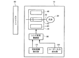
【解決手段】本投射型表示装置10は、表示画像を光学系30を介して投射する投射型表示装置であって、複数の異なる焦点距離または投射距離毎に用意されたレンズ群40,50、60と、光路上に配置するレンズ群を変更するレンズ変更制御を行うレンズ変更制御部80と、を含む。
【選択図】図1PROBLEM TO BE SOLVED: To provide a projection type display device that can cope with a wide range of projection distances by one unit.
The projection display device 10 is a projection display device that projects a display image via an optical system 30, and includes a plurality of lens groups 40, 50 prepared for a plurality of different focal lengths or projection distances. 60, and a lens change control unit 80 that performs lens change control for changing a lens group arranged on the optical path.
[Selection] Figure 1
Description
本発明は、投射型表示装置及び表示方法に関する。 The present invention relates to a projection display device and a display method.
従来より、光源から出射された光束を光学的に処理して光学像を形成し、投写レンズにより光学像を拡大投写する投写型表示装置が知られている。このような投写型表示装置は、会議、学会、展示会等のマルチプレゼンテーションに広く利用されているほか、家庭用のテレビ、DVD鑑賞等にも利用されている。
かかる投写型表示装置は、会議、学会、展示会等のマルチプレゼンテーションのように投射距離の長いものと、家庭でテレビやDVD鑑賞を行う場合のように投射距離の短いものがあるが、これらは光学系を構成するレンズ群が異なるため、別機種として製造されるのが一般的であった。 Such projection display devices include those with a long projection distance such as multi-presentation such as conferences, academic conferences, and exhibitions, and those with a short projection distance such as when watching TV or DVD at home. Since the lens group constituting the optical system is different, it is generally manufactured as a different model.
従って、投射距離が有る程度以上異なる場合には、それぞれの投射距離に対応した機種の投写型表示装置が必要となるという問題点があった。 Therefore, when the projection distances are different from each other to some extent, there is a problem that a projection display device of a model corresponding to each projection distance is required.
本発明は、以上のような問題点に鑑みてなされたものであり、1台で幅広い投射距離に対応可能な投射型表示装置を提供することである。 The present invention has been made in view of the above problems, and it is an object of the present invention to provide a projection display device that can handle a wide range of projection distances with a single unit.
(1)本発明は、表示画像を光学系を介して投射する投射型表示装置であって、複数の異なる焦点距離または投射距離毎に用意されたレンズ群と、光路上に配置するレンズ群を変更するレンズ変更制御を行うレンズ変更制御部と、を含むことを特徴とする。 (1) The present invention is a projection display device that projects a display image via an optical system, and includes a lens group prepared for each of a plurality of different focal lengths or projection distances, and a lens group disposed on an optical path. And a lens change control unit that performs lens change control to be changed.
投射型表示装置とは、例えばプロジェクタである。 The projection display device is, for example, a projector.
ここでレンズ変更制御の対象となるレンズ群は投射型表示装置の光学系の一部でもよく、例えば光学系のなかで投射時の焦点合わせ使用されるレンズ群でもよい。またレンズ変更制御の対象となるレンズ群の位置は例えば光源に近い所に配置されている場合でもよし、投射口に近い側に配置されている場合でもよい。 Here, the lens group to be subjected to lens change control may be a part of the optical system of the projection display device, for example, a lens group used for focusing during projection in the optical system. Further, the position of the lens group to be subjected to lens change control may be arranged near the light source, for example, or may be arranged near the projection opening.
レンズ変更制御部は、自動でレンズ変更制御を行う構成でもいし、ユーザーが手動でレンズ変更制御を行う構成でもよい。 The lens change control unit may be configured to automatically perform lens change control, or may be configured to manually perform lens change control by the user.
光路とは光源から発せられる光の通り道であり、光路上に配置されたレンズによって光を屈折させスクリーン上に拡大映像を投射させる。 An optical path is a path of light emitted from a light source, and refracts light by a lens disposed on the optical path to project an enlarged image on a screen.
レンズ群は焦点距離や投射距離に応じて用意されている。 The lens group is prepared according to the focal length and the projection distance.
本発明によれば光路上に配置するレンズ群を焦点距離や投射距離に応じて最適なレンズ群に変更することができるため、焦点距離や投射距離が大幅に異なる場合でも1台で対応可能な投射型表示装置を提供することができる。 According to the present invention, since the lens group arranged on the optical path can be changed to an optimum lens group according to the focal length and the projection distance, even if the focal length and the projection distance are significantly different, one unit can cope A projection display device can be provided.
(2)本発明の投射型表示装置は、前記複数のレンズ群は、レンズ群単位で一体化して移動するように構成され、前記レンズ変更制御部は、レンズ群単位で回転またはスライドさせて、光路上に配置するレンズ群を変更することを特徴とする。 (2) In the projection display device of the present invention, the plurality of lens groups are configured to move integrally in units of lens groups, and the lens change control unit rotates or slides in units of lens groups, The lens group arranged on the optical path is changed.
レンズ群単位で一体化して移動するように構成されるとは、例えばレンズ群単位でユニット化して、ユニット単位で光路上への切り替えが可能な構成とすることである。例えばいずれかのユニットのユニット内のレンズ群の光軸が光路上にくるよう複数のユニットを回転またはスライドするような機構を設けてもよい。 The term “configured so as to move in units of lens groups” means that, for example, a unit is formed in units of lens groups and the unit can be switched to the optical path. For example, a mechanism may be provided that rotates or slides a plurality of units so that the optical axis of the lens group in any unit is on the optical path.
(3)本発明の投射型表示装置は、投影面までの投射距離を検出する投射距離検出手段をさらに含み、前記レンズ変更制御部は、検出された投射距離に基づき光路上に配置するレンズ群を決定し、決定されたレンズ群が光路上に配置されるようにレンズ変更制御を行うことを特徴とする。 (3) The projection type display device of the present invention further includes a projection distance detecting means for detecting a projection distance to the projection surface, and the lens change control unit is a lens group arranged on the optical path based on the detected projection distance. And lens change control is performed so that the determined lens group is arranged on the optical path.
投影面までの投射距離は、例えば撮像手段(CCDカメラ等)が撮像した投影面の画像に基づき検出する構成でもよい。またレーザーポインタとレーザー光反射時間測定手段とを用いて、レーザー光の速度と反射時間から距離を検出する構成でもよい。 For example, the projection distance to the projection surface may be detected based on an image of the projection surface captured by an imaging unit (CCD camera or the like). Moreover, the structure which detects a distance from the speed and reflection time of a laser beam using a laser pointer and a laser beam reflection time measuring means may be sufficient.
本発明によれば投影面までの投射距離を検出して検出結果に応じて、自動的に光路上に配置するレンズ群の変更制御を行うことができる。従ってユーザーの手を煩わせる事無く投射距離に応じた焦点調整が可能な投射型表示装置を提供することができる。 According to the present invention, it is possible to detect the projection distance to the projection surface and automatically change the lens group arranged on the optical path according to the detection result. Therefore, it is possible to provide a projection display device that can adjust the focus according to the projection distance without bothering the user.
なお投影面の距離検出及び距離に基づくレンズ変更処理は、投射型表示装置の使用開始時に設定モード等を設けて行うようにしてもよい。 Note that the distance detection of the projection plane and the lens changing process based on the distance may be performed by providing a setting mode or the like at the start of use of the projection display device.
(4)本発明の投射型表示装置は、焦点距離または投射距離に関する指示入力を受け付ける受け付け手段をさらに含み、前記レンズ変更制御部は、焦点距離に関する指示入力に基づき、光路上に配置するレンズ群を決定し、決定されたレンズ群が光路上に配置されるようにレンズ変更制御を行うことを特徴とする。 (4) The projection display device of the present invention further includes a receiving unit that receives an instruction input related to a focal length or a projection distance, and the lens change control unit is a lens group arranged on the optical path based on the instruction input related to the focal length. The lens change control is performed so that the determined lens group is arranged on the optical path.
焦点距離または投射距離に関する指示入力とは、焦点距離や投射距離についての選択肢(例えば長焦点、中焦点、短焦点とか、投射距離の長、中、短等)からの選択入力を受け付ける形式でもよいし、焦点距離や投射距離の値を入力する形式でもよい。 The instruction input related to the focal length or the projection distance may be a format that accepts a selection input from choices regarding the focal length or the projection distance (for example, long focus, medium focus, short focus, projection distance length, medium, short, etc.). In addition, a form in which values of focal length and projection distance are input may be used.
なお焦点距離または投射距離に関する指示入力は、投射型表示装置の使用開始時に設定モード等を設けて行うようにしてもよい。 The instruction input regarding the focal length or the projection distance may be performed by providing a setting mode or the like at the start of use of the projection display device.
受け付け手段は投射型表示装置本体やリモートコントローラ等の操作部により実現することができる。 The receiving unit can be realized by an operation unit such as a projection display main body or a remote controller.
本発明によれば、ユーザーは投射距離に関する使用状況に応じて焦点距離または投射距離に関する指示入力を行うことにより、レンズ変更制御を行うことができる。 According to the present invention, the user can perform lens change control by performing an instruction input relating to the focal length or the projection distance in accordance with the usage situation relating to the projection distance.
(5)本発明は、焦点距離または投射距離に応じて用意された複数のレンズ群を含む光学系を有する投射型表示装置を用いた画像表示方法であって、使用するレンズ群を特定するためのレンズ群特定情報を取得するステップと、レンズ群特定情報に基づき光路上に配置するレンズ群を決定し、決定されたレンズ群が光路上に配置されるようにレンズ変更制御を行うステップと、表示画像を光路上に配置されたレンズ群を含む光学系を介して投射するステップと、を含むことを特徴とする表示方法である。 (5) The present invention is an image display method using a projection display apparatus having an optical system including a plurality of lens groups prepared according to a focal length or a projection distance, and for specifying a lens group to be used. Acquiring lens group specifying information, determining a lens group to be arranged on the optical path based on the lens group specifying information, and performing lens change control so that the determined lens group is arranged on the optical path; Projecting a display image through an optical system including a lens group disposed on the optical path.
以下、本発明の好適な実施形態について図面を用いて詳細に説明する。なお、以下に説明する実施の形態は、特許請求の範囲に記載された本発明の内容を不当に限定するものではない。また以下で説明される構成の全てが本発明の必須構成要件であるとは限らない。 DESCRIPTION OF EMBODIMENTS Hereinafter, preferred embodiments of the present invention will be described in detail with reference to the drawings. The embodiments described below do not unduly limit the contents of the present invention described in the claims. Also, not all of the configurations described below are essential constituent requirements of the present invention.
以下、本発明の実施形態に係る投射型表示装置について、図面を参照して説明する。 Hereinafter, a projection display device according to an embodiment of the present invention will be described with reference to the drawings.
図1は、本実施形態に係る投射型表示装置(プロジェクタ)について説明するための図である。 FIG. 1 is a diagram for explaining a projection display device (projector) according to the present embodiment.
本実施形態に係る投射型表示装置(プロジェクタ)10は、表示画像を光学系30を介してスクリーン90等に投射する投射型表示装置であって、光源20、光学系30、レンズ変更制御部80,投射距離検出部110、指示入力受け付け部120を含む。
A projection display device (projector) 10 according to the present embodiment is a projection display device that projects a display image onto a
なお、本実施形態に係る投射型表示装置(プロジェクタ)10は、その他にも図示しない電源部(主電源部やバラスト部)、制御部(投射型表示装置の各種動作の制御や表示する画像の制御を行うプロセッサ等)、その他の投射光学系、冷却部(電源部や光源部を冷却する冷却ファンとその駆動部等)等を含んでもよい。投写光学系は、ランプ等の光源部20その駆動部、液晶ライトバルブ等の液晶パネルとその制御部、投写レンズやプリズム等で構成された光学系30を備えており、プロジェクタ10の外部に備えられたスクリーン90等に画像の投射表示を行うものである。図示しない液晶パネルは、マトリクス状に形成された複数の画素を備えており、光源から射出した光を、制御部から入力される画像信号に基づいて画素毎に変調することによって画像に応じた光学像を形成し、形成された光学像が投写レンズ30によってスクリーン90等に拡大投写される。
The projection display device (projector) 10 according to this embodiment includes a power supply unit (main power supply unit and ballast unit) (not shown) and a control unit (control of various operations of the projection display device and an image to be displayed. A processor that performs control), other projection optical systems, a cooling unit (a cooling fan that cools the power supply unit and the light source unit, and a driving unit thereof), and the like. The projection optical system includes a
一般に投射型表示装置では投射距離に応じて用意された複数のレンズを光路上に光軸に対して垂直に配置することで、焦点のあった画像をスクリーン上に投射するので、投射距離が長い場合と短い場合には使用する投射レンズが異なってくる(焦点距離の異なるレンズを使用する)。 In general, in a projection display device, a plurality of lenses prepared according to the projection distance are arranged on the optical path perpendicular to the optical axis so that a focused image is projected on the screen, so the projection distance is long. In some cases, the projection lens to be used differs depending on the case (use lenses having different focal lengths).
本実施の光学系30は、複数の異なる焦点距離または投射距離毎に用意されたレンズ群(第1のレンズ群40、第2のレンズ群50、第3のレンズ群60)を含む。レンズ変更制御部80は、光路上22に配置するレンズ群40、50、60を変更するレンズ変更制御を行う。
The
また複数のレンズ群(第1のレンズ群40、第2のレンズ群50、第3のレンズ群60)は、レンズ群単位で一体化して移動するように構成され、レンズ変更制御部80は、レンズ群単位で回転またはスライドさせて、光路上22に配置するレンズ群を変更するようにしてもよい。
The plurality of lens groups (the
レンズ群40、50、60は焦点距離や投射距離に応じて用意されている。例えば、例えば焦点距離によって短焦点、中焦点、長焦点の3つに分類し、第1のレンズ群40として短焦点用のレンズ群、第2のレンズ群50として中焦点用のレンズ群、第3のレンズ群60として長焦点用のレンズ群を用意してもよい。また例えば投射距離によって短距離投射(例えば1m以下)、中距離投射(例えば1m〜3m)、長距離投射(例えば3m以上)の3つに分類し、第1のレンズ群40として短距離投射用のレンズ群、第2のレンズ群50として中距離投射用のレンズ群、第3のレンズ群60として長距離投射用のレンズ群を用意してもよい。
The
レンズ変更制御部80は、複数のレンズ群(第1のレンズ群40、第2のレンズ群50、第3のレンズ群60)を手動または自動で回転させる機構を有している。
The lens
投射距離検出部110は、投影距離(スクリーン90までの距離)を検出し、レンズ変更制御部80は、検出された投射距離に基づきレンズ変更制御を行うようにしてもよい。ここで投射距離検出部110は、例えばカメラ等の撮影手段でスクリーンを撮影して、スクリーン上の投射範囲の大きさや所定の2点の位置等を検出し、投射範囲の大きさや所定の2点の位置等に基づき投射距離を演算して求めるようにしてもよい。
The projection
また、レーザー光線等の光をスクリーンに向け投射して反射光を受光するまでの時間を検出し、検出された反射時間に基づき投射距離を演算して求めるようにしてもよい。 Alternatively, the time from projecting light such as a laser beam toward the screen to receiving the reflected light may be detected, and the projection distance may be calculated based on the detected reflection time.
指示入力受け付け部120は、例えばリモコンや本体に設けられたボタン等により実現され、焦点距離に関する指示入力を受け付ける。例えば、焦点距離についてボタンにより「短距離(例えば1メートル以内)」と「長距離(1メートル以上)」を選択したら、画面上に「短距離(例えば1メートル以内)」と「長距離(1メートル以上)」と表示させ、画面上でカーソルを移動させていずれかを選択して確定させる入力を行うことにより実現してもよい。
The instruction
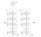
図2は、本実施形態に係る投射型表示装置(プロジェクタ)の光学系の一例を示した図である。 FIG. 2 is a diagram illustrating an example of an optical system of the projection display device (projector) according to the present embodiment.
光学系は、第1の焦点距離に対応して用意された複数のレンズ212−1、212−2、212−3、・・・212−nを第1の軸214に沿って配置した第1のレンズ群210と、第1の焦点距離とは異なる第2の焦点距離に対応して用意された複数のレンズ222−1、222−2、222−3、・・・222−nを第2の軸224に沿って配置した第2のレンズ群220と、を含む。そしてレンズ変更制御部は、光路上に配置するレンズ群をレンズ群単位で回転またはスライドさせて移動させるレンズ切り替える制御を行うようにしてもよい。
In the optical system, a plurality of lenses 212-1, 212-2, 212-3,... 212 -n prepared corresponding to the first focal length are arranged along the
本実施の形態では、レンズ群単位で切り替えるので制御が容易である。また例えば、レンズ群をユニット化して、手動でユニット単位での位置の切り替えが行えるように構成することにより、ユーザーの手動切り替えを実現することができる。 In the present embodiment, since the switching is performed in units of lens groups, control is easy. Further, for example, the user can be manually switched by unitizing the lens group so that the position can be manually switched in units.
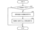
図3は、本実施の形態のレンズ変更制御の処理の流れを示すフローチャートである。 FIG. 3 is a flowchart showing a process flow of lens change control according to the present embodiment.
レンズ変更制御処理は、投射型表示装置の使用開始時にレンズ変更モード等を設けて行うようにしてもよい。 The lens change control process may be performed by providing a lens change mode or the like at the start of use of the projection display device.
例えばレンズ変更モードになると、投射距離設定部は、例えば撮像手段(CCDカメラ等)が撮像した投影面の画像やレーザーポインタから発したレーザー光の反射時間等に基づき投射距離を計算する(ステップS10、S20)。 For example, when the lens change mode is entered, the projection distance setting unit calculates the projection distance based on, for example, the image of the projection surface captured by the imaging means (CCD camera or the like), the reflection time of the laser light emitted from the laser pointer, and the like (step S10). , S20).
次に、レンズ変更制御部は、計算された投射距離に基づき使用するレンズ群を決定し、レンズ群の変更が必要であれば、物理的に使用するレンズ群を変更する制御を行う(ステップS30)
本発明は、実施の形態で説明した構成と実質的に同一の構成(例えば、機能、方法及び結果が同一の構成、あるいは目的及び効果が同一の構成)を含む。また、本発明は、実施の形態で説明した構成の本質的でない部分を置き換えた構成を含む。また、本発明は、実施の形態で説明した構成と同一の作用効果を奏する構成又は同一の目的を達成することができる構成を含む。また、本発明は、実施の形態で説明した構成に公知技術を付加した構成を含む。
Next, the lens change control unit determines a lens group to be used based on the calculated projection distance, and performs control to change the lens group to be physically used if the lens group needs to be changed (step S30). )
The present invention includes configurations that are substantially the same as the configurations described in the embodiments (for example, configurations that have the same functions, methods, and results, or configurations that have the same objects and effects). In addition, the invention includes a configuration in which a non-essential part of the configuration described in the embodiment is replaced. In addition, the present invention includes a configuration that exhibits the same operational effects as the configuration described in the embodiment or a configuration that can achieve the same object. Further, the invention includes a configuration in which a known technique is added to the configuration described in the embodiment.
上記実施の形態では、レンズ群の位置を変更することで光路上に配置されるレンズ群を切り替える場合を例に取り説明したが、光軸の位置を変更して光路を変更することで、光路上に配置されるレンズ群を切り替えるようにしてもよい。例えば光源を移動させることにより光軸の位置を移動させてもよいし、光源からの光を反射させるミラーの角度を変更することにより光軸の位置を移動させてもよい。 In the above embodiment, the case where the lens group disposed on the optical path is switched by changing the position of the lens group has been described as an example. However, by changing the optical path by changing the position of the optical axis, You may make it switch the lens group arrange | positioned on a road. For example, the position of the optical axis may be moved by moving the light source, or the position of the optical axis may be moved by changing the angle of a mirror that reflects light from the light source.
また、プロジェクタは、液晶パネルを用いたプロジェクタには限定されず、例えば、DMD(Digital Micromirror Device)を用いたプロジェクタ等であってもよい。なお、DMDは、米国テキサス・インスツルメンツ社の商標である。 Further, the projector is not limited to a projector using a liquid crystal panel, and may be a projector using a DMD (Digital Micromirror Device), for example. DMD is a trademark of Texas Instruments Incorporated.
10 プロジェクタ、20 光源、22 光路、30 光学系、40 第1のレンズ群、50 第2のレンズ群、60 第3のレンズ群、80 レンズ変更制御部、90 スクリーン、110 投射距離検出部、120 指示入力受け付け部
DESCRIPTION OF
Claims (5)
複数の異なる焦点距離または投射距離毎に用意されたレンズ群と、
光路上に配置するレンズ群を変更するレンズ変更制御を行うレンズ変更制御部と、
を含むことを特徴とする投射型表示装置。 A projection display device that projects a display image via an optical system,
A lens group prepared for each of a plurality of different focal lengths or projection distances,
A lens change control unit for performing lens change control for changing a lens group disposed on the optical path;
A projection type display device comprising:
前記複数のレンズ群は、レンズ群単位で一体化して移動するように構成され、
前記レンズ変更制御部は、
レンズ群単位で回転またはスライドさせて、光路上に配置するレンズ群を変更することを特徴とする投射型表示装置。 In claim 1,
The plurality of lens groups are configured to move integrally in units of lens groups,
The lens change control unit
A projection type display device characterized in that a lens group arranged on an optical path is changed by rotating or sliding in units of lens groups.
投影面までの投射距離を検出する投射距離検出手段をさらに含み、
前記レンズ変更制御部は、
検出された投射距離に基づき光路上に配置するレンズ群を決定し、決定されたレンズ群が光路上に配置されるようにレンズ変更制御を行うことを特徴とする投射型表示装置。 In any one of Claims 1-2.
A projection distance detecting means for detecting a projection distance to the projection surface;
The lens change control unit
A projection type display device characterized by determining a lens group to be arranged on an optical path based on a detected projection distance and performing lens change control so that the decided lens group is arranged on the optical path.
焦点距離または投射距離に関する指示入力を受け付ける受け付け手段をさらに含み、
前記レンズ変更制御部は、
焦点距離に関する指示入力に基づき、光路上に配置するレンズ群を決定し、決定されたレンズ群が光路上に配置されるようにレンズ変更制御を行うことを特徴とする投射型表示装置。 In any one of Claims 1 thru | or 3,
A receiving unit for receiving an instruction input related to the focal length or the projection distance;
The lens change control unit
A projection-type display device that determines a lens group to be arranged on an optical path based on an instruction input related to a focal length and performs lens change control so that the determined lens group is arranged on the optical path.
使用するレンズ群を特定するためのレンズ群特定情報を取得するステップと、
レンズ群特定情報に基づき光路上に配置するレンズ群を決定し、決定されたレンズ群が光路上に配置されるようにレンズ変更制御を行うステップと、
表示画像を光路上に配置されたレンズ群を含む光学系を介して投射するステップと、
を含むことを特徴とする表示方法。 A display method using a projection display device having an optical system including a plurality of lens groups prepared according to a focal length or a projection distance,
Obtaining lens group specifying information for specifying a lens group to be used;
Determining a lens group to be disposed on the optical path based on the lens group identification information, and performing lens change control so that the determined lens group is disposed on the optical path;
Projecting a display image through an optical system including a lens group disposed on the optical path;
A display method comprising:
Priority Applications (1)
| Application Number | Priority Date | Filing Date | Title |
|---|---|---|---|
| JP2007053886A JP2008216632A (en) | 2007-03-05 | 2007-03-05 | Projection display |
Applications Claiming Priority (1)
| Application Number | Priority Date | Filing Date | Title |
|---|---|---|---|
| JP2007053886A JP2008216632A (en) | 2007-03-05 | 2007-03-05 | Projection display |
Publications (1)
| Publication Number | Publication Date |
|---|---|
| JP2008216632A true JP2008216632A (en) | 2008-09-18 |
Family
ID=39836746
Family Applications (1)
| Application Number | Title | Priority Date | Filing Date |
|---|---|---|---|
| JP2007053886A Withdrawn JP2008216632A (en) | 2007-03-05 | 2007-03-05 | Projection display |
Country Status (1)
| Country | Link |
|---|---|
| JP (1) | JP2008216632A (en) |
Cited By (2)
| Publication number | Priority date | Publication date | Assignee | Title |
|---|---|---|---|---|
| CN115248526A (en) * | 2022-02-18 | 2022-10-28 | 深圳市晶鸿电子有限公司 | Household projection device, control method and storage medium |
| WO2025263825A1 (en) * | 2024-06-17 | 2025-12-26 | 삼성전자 주식회사 | Projection device and operation method thereof |
-
2007
- 2007-03-05 JP JP2007053886A patent/JP2008216632A/en not_active Withdrawn
Cited By (3)
| Publication number | Priority date | Publication date | Assignee | Title |
|---|---|---|---|---|
| CN115248526A (en) * | 2022-02-18 | 2022-10-28 | 深圳市晶鸿电子有限公司 | Household projection device, control method and storage medium |
| CN115248526B (en) * | 2022-02-18 | 2022-12-27 | 深圳市晶鸿电子有限公司 | Household projection device, control method and storage medium |
| WO2025263825A1 (en) * | 2024-06-17 | 2025-12-26 | 삼성전자 주식회사 | Projection device and operation method thereof |
Similar Documents
| Publication | Publication Date | Title |
|---|---|---|
| US8702244B2 (en) | Multimedia player displaying projection image | |
| US9936179B2 (en) | Image projection apparatus and method of controlling the same, and non-transitory computer-readable storage medium | |
| EP3435661A1 (en) | Projection display apparatus including eye tracker | |
| JP4993029B2 (en) | Projection display device and adjustment method thereof | |
| JP2007517243A (en) | Display apparatus and method | |
| JP2011154345A (en) | Projection video display apparatus and image adjustment method | |
| WO2022012651A1 (en) | Projection method, projection device and storage medium | |
| JP5217630B2 (en) | Projector and multi-projection system | |
| JP2012078658A (en) | Projection type video display device | |
| CN104658462A (en) | Porjector and method of controlling projector | |
| JP2013195498A (en) | Multi-projector system | |
| JP7177936B2 (en) | Projection type image display device | |
| JP2015145894A (en) | Projection display | |
| JP2005189733A (en) | projector | |
| US8902215B2 (en) | Method and mobile terminal for adjusting focus of a projected image | |
| JP2008216632A (en) | Projection display | |
| JP7214443B2 (en) | Image projection device and its control method | |
| JP5293861B2 (en) | Projector, imaging device | |
| KR101550606B1 (en) | Curved display apparatus for vehicle | |
| JP2012053227A (en) | Projection type video display device | |
| CN110596996B (en) | Projector and automatic geometric correction method | |
| KR100686525B1 (en) | Projector Camera System and Focusing Method for Implementation of Augmented Reality | |
| JP2006285012A (en) | projector | |
| JP2018101078A (en) | Projection type video display device | |
| JP2005070412A (en) | Image projection apparatus and focus adjustment method thereof |
Legal Events
| Date | Code | Title | Description |
|---|---|---|---|
| RD04 | Notification of resignation of power of attorney |
Free format text: JAPANESE INTERMEDIATE CODE: A7424 Effective date: 20080702 |
|
| A300 | Withdrawal of application because of no request for examination |
Free format text: JAPANESE INTERMEDIATE CODE: A300 Effective date: 20100511 |