JP2008201416A - Manufacturing method of casting suspension member - Google Patents
Manufacturing method of casting suspension member Download PDFInfo
- Publication number
- JP2008201416A JP2008201416A JP2008140629A JP2008140629A JP2008201416A JP 2008201416 A JP2008201416 A JP 2008201416A JP 2008140629 A JP2008140629 A JP 2008140629A JP 2008140629 A JP2008140629 A JP 2008140629A JP 2008201416 A JP2008201416 A JP 2008201416A
- Authority
- JP
- Japan
- Prior art keywords
- suspension member
- mounting base
- mounting
- manufacturing
- suspension
- Prior art date
- Legal status (The legal status is an assumption and is not a legal conclusion. Google has not performed a legal analysis and makes no representation as to the accuracy of the status listed.)
- Granted
Links
Images


Abstract
Description
本発明は、鋳造によって形成されると共にサスペンションアームの端部を挟み込むように揺動可能に取り付けるための一対の取付壁を備えた鋳造サスペンションメンバの製造方法に関する。 The present invention relates to a method for manufacturing a cast suspension member that is formed by casting and includes a pair of mounting walls that are swingably mounted so as to sandwich an end portion of a suspension arm.
従来から、サスペンションアームやステアリングギヤボックスを支持するための部材としてサスペンションメンバが配設されている。一般にはサスペンションメンバは鋼板をプレス成形することによって製作されるが、昨今では軽量化の観点からサスペンションメンバをアルミニウム合金等を使って鋳造で製作することに対するニーズが高まっている。
ところで、サスペンションアームのサスペンションメンバへの取付構造として、アーム先端に圧入されたブッシュをサスペンションメンバに形成された一対の取付壁の間に挟み込むように挿入配置し、ボルト及びナットで揺動可能に固定する構成を採ることがある。 By the way, as a structure for mounting the suspension arm to the suspension member, a bush press-fitted to the tip of the arm is inserted and arranged so as to be sandwiched between a pair of mounting walls formed on the suspension member, and fixed with a bolt and a nut so as to be swingable. The structure to be taken may be taken.
この場合、サスペンションアームからサスペンションメンバへの入力を考慮すると、一対の取付壁の板厚を厚くする等して強度を高めることが望ましい。 In this case, considering the input from the suspension arm to the suspension member, it is desirable to increase the strength by increasing the thickness of the pair of mounting walls.
しかし、一対の取付壁の板厚を厚くすると、サスペンションアームを一対の取付壁間に組付けた際に比較的大きな組付応力が発生するという問題が生じる。より詳しく説明すると、サスペンションアームの一対の取付壁への組付を可能とするためには、一対の取付壁の対向面間の距離をブッシュの軸長よりも若干大きめに設定し、各取付壁の内側の面とブッシュの軸方向の端面との間に僅かな隙間をそれぞれ設定する必要がある。 However, if the plate thickness of the pair of mounting walls is increased, there arises a problem that a relatively large mounting stress is generated when the suspension arm is assembled between the pair of mounting walls. More specifically, in order to allow the suspension arm to be attached to a pair of mounting walls, the distance between the opposing surfaces of the pair of mounting walls is set slightly larger than the axial length of the bush, and each mounting wall It is necessary to set a slight gap between the inner surface of the bush and the axial end surface of the bush.
ところが、前記隙間を設定した場合、ボルトをナットへ締め込むと、一対の取付壁が隙間の分だけ互いに接近する方向へそれぞれ変形することになるが、サスペンションアームからの入力を考慮して取付壁の板厚を厚くすると、板厚の増加に伴って取付壁の変形部位に生じる組付応力も大きくなる。特に鋳造サスペンションメンバの場合、プレス成形品のサスペンションメンバよりも元々疲労強度が低いため、組付応力が大きくなるのは好ましくない。 However, when the gap is set, when the bolt is tightened into the nut, the pair of mounting walls are deformed in the direction of approaching each other by the gap, but the mounting wall is taken into account in consideration of the input from the suspension arm. When the plate thickness is increased, the assembling stress generated at the deformed portion of the mounting wall increases as the plate thickness increases. In particular, in the case of a cast suspension member, since the fatigue strength is originally lower than that of a suspension member of a press-formed product, it is not preferable that the assembly stress is increased.
上述したように、鋳造サスペンションメンバの場合、サスペンションアームからサスペンションメンバへの入力に対する強度確保とサスペンションアームをサスペンションメンバへ組み付ける際に生じる組付応力の増加防止とは背反事項であり、両立させることが難しい。 As described above, in the case of a cast suspension member, securing the strength against the input from the suspension arm to the suspension member and preventing the increase of the assembly stress generated when the suspension arm is assembled to the suspension member are contradictory matters, and it is possible to achieve both. difficult.
本発明は上記事実を考慮し、サスペンションアームからサスペンションメンバへの荷重入力に対する強度確保とサスペンションアームのサスペンションメンバへの組付時に生じる組付応力の増加防止とを両立させることができる鋳造サスペンションメンバの製造方法を得ることが目的である。 In view of the above facts, the present invention provides a cast suspension member capable of ensuring both strength against load input from the suspension arm to the suspension member and preventing increase in assembly stress generated when the suspension arm is assembled to the suspension member. The purpose is to obtain a manufacturing method.
請求項1記載の本発明に係る鋳造サスペンションメンバの製造方法は、サスペンションアームの端部を挟み込むように揺動可能に締結具で取り付けるための一対の取付壁を備えた鋳造サスペンションメンバの製造方法であって、成形型の鋳抜き方向を本来の抜き勾配分だけ片側へ振ることにより、一方の取付壁の外側の面を前記サスペンションアームの端部の取付面に対して平行にした、ことを特徴としている。 The method of manufacturing a cast suspension member according to the first aspect of the present invention is a method of manufacturing a cast suspension member having a pair of mounting walls that are swingably mounted with a fastener so as to sandwich the end of the suspension arm. And, the outer surface of one mounting wall is made parallel to the mounting surface at the end of the suspension arm by swinging the casting direction of the mold to one side by the original draft angle. It is said.
請求項1記載の本発明の作用は、以下の通りである。 The effect | action of this invention of Claim 1 is as follows.
サスペンションメンバにおける一対の取付壁の外側の面は、締結具で締結する際の座面となるから、両側ともサスペンションアームの端部の取付面に対して平行である必要がある。従って、従来では、成形型に形成される凹部の形状を抜き勾配を考慮したテーパ形状にして、成形後の二次加工で取付壁の外側の面及び内側の面をそれぞれ削り、これによりサスペンションアームの端部の取付面に対して外側の面を平行な面としていた。なお、この場合、鋳抜き方向は、垂直になる。換言すれば、従来では、鋳抜き方向を垂直にできる代わりに、一対の取付壁の外側の面及び内側の面のすべて(合計4面)について二次加工が必要となる製造方法であった。 Since the outer surfaces of the pair of mounting walls in the suspension member serve as seating surfaces when fastened with fasteners, both sides need to be parallel to the mounting surface at the end of the suspension arm. Therefore, conventionally, the concave portion formed in the molding die is tapered in consideration of the draft angle, and the outer surface and the inner surface of the mounting wall are respectively cut by the secondary processing after the molding, thereby the suspension arm. The outer surface was parallel to the mounting surface at the end of the. In this case, the casting direction is vertical. In other words, conventionally, the manufacturing method requires secondary processing on all of the outer surfaces and the inner surfaces of the pair of mounting walls (total of four surfaces) instead of making the casting direction vertical.
しかし、本発明では、成形型の鋳抜き方向を本来の抜き勾配分だけ片側に振ることにより、一方の取付壁の外側の面をサスペンションアームの端部の取付面に対して平行にしたので、少なくとも一方の取付壁の外側の面については二次加工をしなくても、サスペンションアームの端部の取付面に対して平行な面を得ることができる。従って、その分、二次加工が不要となるので、製造工数の削減を図ることができ、コスト削減に資する。 However, in the present invention, the outer surface of one mounting wall is made parallel to the mounting surface at the end of the suspension arm by swinging the casting direction of the mold to one side by the original draft angle. A surface parallel to the attachment surface at the end of the suspension arm can be obtained without performing secondary processing on the outer surface of at least one of the attachment walls. Accordingly, secondary processing is not necessary, so that the number of manufacturing steps can be reduced, which contributes to cost reduction.
また、上記の如くして鋳造サスペンションメンバを製造することから、一方の取付壁の板厚を他方の取付壁の板厚よりも厚くする等の手法を使うことにより、一方の取付壁の剛性を他方の取付壁の剛性よりも相対的に高くすることができる。そうすることにより、サスペンションアームからの入力に対する荷重分担が変化する。すなわち、一方の取付壁の方が他方の取付壁よりも荷重負担が大きくなる。つまり、一方の取付壁の方で、サスペンションアームからの入力に対する剛性を確保することができる。 In addition, since the cast suspension member is manufactured as described above, the rigidity of one mounting wall is increased by using a method such as making the thickness of one mounting wall thicker than the thickness of the other mounting wall. It can be made relatively higher than the rigidity of the other mounting wall. By doing so, the load sharing for the input from the suspension arm changes. That is, the load burden on one mounting wall is greater than that on the other mounting wall. That is, the rigidity with respect to the input from the suspension arm can be ensured on one of the mounting walls.
逆に、サスペンションアームのサスペンションメンバへの組付時には、剛性が相対的に高い一方の取付壁は殆ど変形せず、剛性が相対的に他方の取付壁が組付方向に変形する。よって、組付時に生じる組付応力は、他方の取付壁の側により大きく発生することになるが、他方の取付壁は一方の取付壁よりも相対的に「柔」に構成されているため、発生する組付応力自体を抑えることができる。 Conversely, when the suspension arm is assembled to the suspension member, one of the attachment walls having relatively high rigidity is hardly deformed, and the other attachment wall is relatively deformed in the assembling direction. Therefore, the assembly stress generated at the time of assembly is generated more largely on the other mounting wall side, but the other mounting wall is relatively "softer" than the one mounting wall, The generated assembly stress itself can be suppressed.
上記より、サスペンションアームからサスペンションメンバへの荷重入力に対する強度確保とサスペンションアームのサスペンションメンバへの組付時に生じる組付応力の増加防止とを両立させ得る鋳造サスペンションメンバを製造するに際して、製造設備の大幅な変更を強いられることがない。 From the above, when manufacturing a cast suspension member that can achieve both securing strength against load input from the suspension arm to the suspension member and preventing increase in assembly stress that occurs when the suspension arm is assembled to the suspension member, the manufacturing equipment can be greatly increased. There is no compelling change.
以上説明したように、請求項1記載の本発明に係る鋳造サスペンションメンバの製造方法は、サスペンションアームの端部を挟み込むように揺動可能に締結具で取り付けるための一対の取付壁を備えた鋳造サスペンションメンバの製造方法において、成形型の鋳抜き方向を本来の抜き勾配分だけ片側へ振ることにより、一方の取付壁の外側の面をサスペンションアームの端部の取付面に対して平行にしたので、サスペンションメンバの鋳造後の二次加工を削減することができ、その結果、サスペンションメンバの製造コストの削減並びに製造の容易化を図ることができるという優れた効果を有する。 As described above, the method for manufacturing a cast suspension member according to the first aspect of the present invention includes a pair of mounting walls that are swingably mounted with a fastener so as to sandwich the end of the suspension arm. In the suspension member manufacturing method, the outer surface of one mounting wall is made parallel to the mounting surface at the end of the suspension arm by swinging the casting direction of the mold to one side by the original draft angle. The secondary processing after casting of the suspension member can be reduced, and as a result, the manufacturing cost of the suspension member can be reduced and the manufacturing can be facilitated.
また、請求項1記載の本発明に係る鋳造サスペンションメンバの製造方法によれば、上記の如くして鋳造サスペンションメンバを製造することから、一方の取付壁の板厚を他方の取付壁の板厚よりも厚くする等の手法を使うことにより、サスペンションアームからサスペンションメンバへの荷重入力に対する強度確保とサスペンションアームのサスペンションメンバへの組付時に生じる組付応力の増加防止とを両立させ得る鋳造サスペンションメンバを、製造設備の大幅な変更を強いられることなく、製造することができるという優れた効果を有する。 According to the method for manufacturing a cast suspension member according to the first aspect of the present invention, since the cast suspension member is manufactured as described above, the thickness of one mounting wall is set to the thickness of the other mounting wall. A cast suspension member that can achieve both securing strength against load input from the suspension arm to the suspension member and preventing increase in assembly stress generated when the suspension arm is assembled to the suspension member. Can be manufactured without being forced to change the manufacturing equipment significantly.
〔第1実施形態〕 [First Embodiment]
以下、図1〜図6を用いて、本発明に係る鋳造サスペンションメンバの製造方法によって製造された第1実施形態に係るフロントサスペンションメンバ10について説明する。
Hereinafter, the
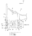
図4には本実施形態に係るフロントサスペンションメンバ10の全体構成を示す斜視図が示されており、又図1には当該フロントサスペンションメンバ10の要部を裏面側から見て示す拡大斜視図が示されている。また、図2には当該フロントサスペンションメンバ10の要部を示す縦断面図が示されており、更に図3には当該フロントサスペンションメンバ10の要部を示す横断面図が示されている。
FIG. 4 is a perspective view showing the overall configuration of the
図4に示されるように、フロントサスペンションメンバ10は、車両幅方向に沿って前後に平行に配置された一対のフロントサスペンションフロントクロスメンバ12及びフロントサスペンションリヤクロスメンバ14と、車両前後方向に沿って左右に平行に配置された一対のフロントサスペンションサイドメンバ16、18とを含んで構成されており、全体としては平面視で井型形状に形成されている。また、このフロントサスペンションメンバ10は、アルミニウム合金を用いた鋳造(アルミダイキャスト)によって構成されている。
As shown in FIG. 4, the
上述したフロントサスペンションメンバ10におけるフロントサスペンションフロントクロスメンバ12の前側にはステアリングギヤボックス20(図3参照)が配設されるようになっており、又フロントサスペンションメンバ10における両端部の外側には左右一対のフロントサスペンションアーム22(図2参照)が揺動可能に軸支されるようになっている。
A steering gear box 20 (see FIG. 3) is arranged on the front side of the front suspension
より具体的に説明すると、図1〜図3に示されるように、フロントサスペンションメンバ10のフロントコーナー部には、各々プレート状に一体形成された前側取付ベース24及び後側取付ベース26が前後に平行に配置されている。これらの前側取付ベース24及び後側取付ベース26の外側の角部にはボルト挿通孔28が同軸上に形成されており、当該ボルト挿通孔28が形成された部分がフロントサスペンションアーム22を取り付けるための前側アーム取付部30及び後側アーム取付部32とされている。かかる前側アーム取付部30と後側アーム取付部32との間にフロントサスペンションアーム22の内端部に圧入されたブッシュ34(図2参照)が挿入され、ボルト36及びナット38によって揺動可能に取り付けられている。
More specifically, as shown in FIGS. 1 to 3, a
また、上述した前側取付ベース24の内側の角部には、扁平な略円筒形状に形成されると共にステアリングギヤボックス20を取り付けるためのギヤボックス取付部42(図3参照)が一体に形成されている。ギヤボックス取付部42の軸芯部には、ボルト挿通孔43が形成されている。ステアリングギヤボックス20は、左右一対のギヤボックス取付部42へボルト44及びナット46によって固定されている。
Further, a gear box mounting portion 42 (see FIG. 3) for mounting the
ここまでの構成を総括すると、本実施形態に係る鋳造サスペンションメンバ構造では、フロントサスペンションメンバ10における前側アーム取付部30とギヤボックス取付部42とが、車両幅方向に沿って立設状態で配置されたプレート状の前側取付ベース24によって車両幅方向に相互に連結された構造となっている。さらに、上述した前側アーム取付部30とギヤボックス取付部42とは、プレス成形によって帯板状に形成された金属製(鋼板製)のプレート(ブレース)48(図2参照)によって相互に連結されている。
Summarizing the configuration up to this point, in the cast suspension member structure according to the present embodiment, the front
ここで、図2等に示されるように、本実施形態では、上述したサスペンションアーム22の端部を挟み込んだ状態で揺動可能に軸支する「一対の取付壁」としての前側取付ベース24及び後側取付ベース26の剛性比を異ならせている。より具体的に説明すると、サスペンションアーム22からの入力Fの荷重作用方向側に位置する後側取付ベース26の後側アーム取付部32の板厚を、前側取付ベース24の前側アーム取付部30の板厚よりも厚くすることで、前者の剛性を後者の剛性よりも相対的に高めている。
Here, as shown in FIG. 2 and the like, in the present embodiment, the front mounting
さらに、図1に示されるように、後側取付ベース26の後方側には、略面直角方向(略車両前後方向)に沿って一対の補強リブ50が形成されている。これらの補強リブ50の各前端部は後側取付ベース26の後面側に接続されており、当該後側取付ベース26をフロントサスペンションアーム22からの入力に対して支持する機能を果たしている。
Further, as shown in FIG. 1, a pair of reinforcing
次に、本実施形態に係る鋳造によるフロントサスペンションメンバ10の製造方法について説明し、その説明を通して本実施形態の作用並びに効果について説明する。
Next, a method for manufacturing the
図5は従来のフロントサスペンションメンバの製造方法の概要を模式図で示したものであり、又図6は本実施形態に係るフロントサスペンションメンバ10の製造方法の概要を模式図で示したものである。以下、両者を対比しながら、本実施形態に係るフロントサスペンションメンバ10の製造方法について説明する。
FIG. 5 is a schematic diagram showing an outline of a conventional method for manufacturing a front suspension member, and FIG. 6 is a schematic diagram showing an outline of a method for manufacturing the
従来では、図5(A)に示されるように、最終的には後側取付ベース26’を形成する凹部54を下型56に等脚台形状に形成していた。なお、下型56に上型58が合わされたときに形成される隙間60は、前側取付ベース24’を形成するためのものである。そして、鋳込み後、図5(B)に示されるように、下型56及び上型58を互いに離間する方向でかつ垂直方向を鋳抜き方向(矢印Pでこれを示す)として脱型し、一対の前側取付ベース24’及び後側取付ベース26’を備えた製品62(フロントサスペンションメンバ)を得るというものであった。
Conventionally, as shown in FIG. 5A, the
この場合、製品62に形成された後側取付ベース26’は等脚台形状の断面を持つことになる。また、前側取付ベース24’も傾斜した形状になる。そこで、ボルト36及びナット38による締結を可能とするために、二次加工によって、前側取付ベース24’の内側の面24’A及び後側取付ベース26’の内側の面26’A並びに前側取付ベース24’の外側の面24’B及び後側取付ベース26’の外側の面26’Bの合計4面をすべて垂直面に仕上げる。なお、前側取付ベース24’の内側の面24’A及び後側取付ベース26’の内側の面26’Aを垂直面にする必要があるのは、フロントサスペンションアーム22のブッシュ34の取付面と面接触するからである。また、前側取付ベース24’の外側の面24’B及び後側取付ベース26’の外側の面26’Bを垂直面にする必要があるのは、ボルト36及びナット38を締め込む際の締結座面となるからである。
In this case, the rear mounting base 26 'formed on the
従って、従来の製造方法によると、合計4面について二次加工が必要となり、その分だけ、製造工数が増えると共にコストもかかっていた。 Therefore, according to the conventional manufacturing method, secondary processing is required for a total of four surfaces, which increases the number of manufacturing steps and costs.
これに対し、本実施形態に係るフロントサスペンションメンバ12の製造方法では、図6に示されるように、下型64と上型66の鋳抜き方向を本来の抜き勾配分だけ片側(図6では、反時計方向)へ振ることにより、後側取付ベース26の外側の面26Bを最初から垂直面にすることができる。この場合、鋳抜き方向は垂直方向ではなく、図5(B)のθ分だけ図上反時計方向へ振られた矢印Q方向となる。また、鋳抜き方向をθだけ振った分、後側取付ベース26の内側の面26Aは合計2θの傾斜面となる。
In contrast, in the method for manufacturing the
このように本実施形態では、後側取付ベース26の外側の面26Bについては二次加工をしなくても、フロントサスペンションアーム22の端部のブッシュ34の取付面に対して平行な面を得ることができるので、その分、二次加工が不要となる。従って、製造工数の削減を図ることができ、コスト削減に資する。また、最初から平行な面が形成されるため、加工精度を気にする必要もなくなる。従って、前側取付ベース24及び後側取付ベース26を備えたフロントサスペンションメンバ10の製造が容易になる。
Thus, in the present embodiment, a surface parallel to the mounting surface of the
補足すると、本実施形態の場合、前側取付ベース24の内側の面24A及び外側の面24Bも垂直面にできるため、前記効果が得られる。ただ実際には、前側取付ベース24の内側の面24Aはブッシュ34の取付面が当接するため、平面度を高める等の理由から二次加工を行う。また、前側取付ベース24の外側の面24Bについては、本実施形態の場合、プレート48が装着される関係で、やはり二次加工をしている。
Supplementally, in the case of the present embodiment, the
更に補足すると、図2に二次加工の有無の様子が解るがように、二次加工前の状態を二点鎖線で示しておいた。前側取付ベース24の内側の面24A及び外側の面24Bの二次加工前の状態は二点鎖線a、bである。後側取付ベース26の内側の面26Aの二次加工前の状態は二点鎖線cである。後側取付ベース26の外側の面26Bには二次加工は施されていない。
Further supplementally, the state before the secondary processing is shown by a two-dot chain line so that the state of the presence or absence of the secondary processing is understood in FIG. The state before the secondary processing of the
以上説明したように、本実施形態に係る鋳造サスペンションメンバ構造による場合、後側取付ベース26の板厚を前側取付ベース24の板厚よりも厚くしたので、フロントサスペンションアーム22からの入力に対する荷重分担が変化する。すなわち、図2に示されるように、フロントサスペンションアーム22からの入力Fに対し、後側取付ベース26の荷重負担Frは、前側取付ベース24の荷重負担Ffよりも大きくなる(Fr>Ff)。つまり、後側取付ベース26の方で、フロントサスペンションアーム22からの入力Fに対する剛性を確保することができる。
As described above, in the case of the cast suspension member structure according to the present embodiment, since the plate thickness of the rear mounting
逆に、フロントサスペンションアーム22のフロントサスペンションメンバ10の前側取付ベース24及び後側取付ベース26への組付時には、剛性が相対的に高い後側取付ベース26は殆ど変形せず、剛性が相対的に低い前側取付ベース24が組付方向に変形する。よって、組付時に生じる組付応力は、前側取付ベース24の側により大きく発生することになるが、前側取付ベース24は後側取付ベース26よりも相対的に柔に構成されているため、発生する組付応力自体を抑えることができる。なお、組付応力は、締結時に作用する荷重によって変形が生じる図2及び図3のS線矢視部に生じる。
Conversely, when the
総括すると、本実施形態に係る鋳造サスペンションメンバ構造によれば、フロントサスペンションアーム22からフロントサスペンションメンバ10への荷重入力に対する強度確保とフロントサスペンションアーム22のフロントサスペンションメンバ10への組付時に生じる組付応力の増加防止とを両立させることができる。
In summary, according to the cast suspension member structure of the present embodiment, the strength is secured against the load input from the
また、本実施形態に係る鋳造サスペンションメンバの製造方法による場合、フロントサスペンションメンバ10の鋳造後の二次加工を削減することができ、その分だけ、フロントサスペンションメンバ10の製造コストの削減並びに製造の容易化を図ることができる。
Further, according to the method for manufacturing the cast suspension member according to the present embodiment, the secondary processing after the casting of the
さらに、この製造方法による場合、基本的には鋳抜き方向を従来の型勾配分だけ片側へ振るというものであるから、(下型64及び上型66の形状は変更する必要があるものの)板厚が異なる一対の取付壁(前側取付ベース24、後側取付ベース26)を備えたフロントサスペンションメンバ10を製造するに際して、製造設備の大幅な変更を強いられることがないというメリットがある。
Furthermore, according to this manufacturing method, the casting direction is basically swung to one side by the amount corresponding to the conventional mold gradient, so the plate (although the shapes of the lower mold 64 and the
〔第2実施形態〕 [Second Embodiment]
以下、図7及び図8を用いて、本発明に係る鋳造サスペンションメンバの製造方法によって製造された第2実施形態について説明する。なお、前述した第1実施形態と同一構成部分については、同一番号を付してその説明を省略する。 Hereinafter, a second embodiment manufactured by the method for manufacturing a cast suspension member according to the present invention will be described with reference to FIGS. 7 and 8. In addition, about the same component as 1st Embodiment mentioned above, the same number is attached | subjected and the description is abbreviate | omitted.
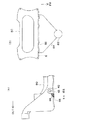
図7には、従来の鋳造方法でフロントサスペンションメンバ80を製造した場合の問題点が示されている。図7(B)に示されるように、湯口82からの鋳込み後に湯道84を切断する場合、フロントサスペンションメンバ80の前面に沿って過不足なく切断することは困難であるため、通常は切断線Rに沿って湯道84を切断する。このとき、図7(A)に示されるように、フロントサスペンションメンバ80側に残った切残し部86は、フロントサスペンションメンバ80の前面の下縁に直線状に形成される。この切残し部86がギヤボックス取付部42と重なってしまうが、ギヤボックス取付部42の隣接部位は元々応力集中が生じる高応力部88となるため、この高応力部88に切残し部86が重なると、更に応力集中が生じるという課題があった。
FIG. 7 shows a problem when the
これに対し、図8に示されるように、高応力部88を避けるかたちで、切残し部90を斜めに配置することにより、図7の切残し部86とギヤボックス取付部42とが重なることによる応力増加分を排除することができる。つまり、本実施形態に係るフロントサスペンションメンバ92では、高応力部94への応力集中を最小限に抑えることができる。
On the other hand, as shown in FIG. 8, the
〔実施形態の補足説明〕 [Supplementary explanation of the embodiment]
上述した各実施形態では、フロントサスペンションメンバ10、92に対して本発明に係る鋳造サスペンションメンバの製造方法を適用したが、これに限らず、リヤサスペンションメンバに本発明を適用することも可能である。
In each of the above-described embodiments, the method for manufacturing a cast suspension member according to the present invention is applied to the
また、上述した第1実施形態では、後側取付ベース26の板厚を前側取付ベース24の板厚よりも厚くすると共に、後側取付ベース26の剛性を高める補強リブ50、52を設定する構成を採ったが、これに限らず、いずれか一方のみを採用してもよい。さらに、前側取付ベース24及び後側取付ベース26のいずれを高剛性化するかについては、入力荷重との関係で適宜選択すればよい。概念的には、荷重分担に変化を付けるべく、高剛性部(厚肉部)と低剛性部(薄肉部)が設けられる構成であればよい。また、剛軟を付けるための構成は、板厚を異ならせる手法やリブの有無或いは多少を設定する手法以外の構成も含まれる。例えば、一方には開口部を形成し他方には開口部を形成しない等であってもよい。
In the first embodiment described above, the configuration is such that the reinforcing
さらに、上述した第2実施形態では、フロントサスペンションメンバ10の前面にギヤボックス取付部42が配置される構成に対して本発明を適用したが、これに限らず、種々の部材(例えば、操舵系部材、懸架系部材、エンジンマウント等)の取付座に対して本発明は適用可能である。
Further, in the above-described second embodiment, the present invention is applied to the configuration in which the gear
10 フロントサスペンションメンバ
20 ステアリングギヤボックス
22 フロントサスペンションアーム
24 前側取付ベース(一方の取付壁)
26 後側取付ベース(他方の取付壁)
30 前側アーム取付部
32 後側アーム取付部
34 ブッシュ
36 ボルト(締結具)
38 ナット(締結具)
42 ギヤボックス取付部(取付座)
50 補強リブ
64 下型(成形型)
66 上型(成形型)
84 湯道
90 切残し部
92 フロントサスペンションメンバ
F 入力
10
26 Rear mounting base (the other mounting wall)
30 Front
38 Nut (fastener)
42 Gearbox mounting part (mounting seat)
50 Reinforcing ribs 64 Lower mold (molding mold)
66 Upper mold (molding mold)
84
Claims (1)
成形型の鋳抜き方向を本来の抜き勾配分だけ片側へ振ることにより、一方の取付壁の外側の面を前記サスペンションアームの端部の取付面に対して平行にした、
ことを特徴とする鋳造サスペンションメンバの製造方法。 A method for manufacturing a cast suspension member comprising a pair of mounting walls for swingably mounting with a fastener so as to sandwich an end portion of a suspension arm,
The outer surface of one mounting wall was made parallel to the mounting surface at the end of the suspension arm by swinging the casting direction of the mold to one side by the original draft angle,
A method for manufacturing a cast suspension member.
Priority Applications (1)
| Application Number | Priority Date | Filing Date | Title |
|---|---|---|---|
| JP2008140629A JP4780145B2 (en) | 2008-05-29 | 2008-05-29 | Manufacturing method of casting suspension member |
Applications Claiming Priority (1)
| Application Number | Priority Date | Filing Date | Title |
|---|---|---|---|
| JP2008140629A JP4780145B2 (en) | 2008-05-29 | 2008-05-29 | Manufacturing method of casting suspension member |
Related Parent Applications (1)
| Application Number | Title | Priority Date | Filing Date |
|---|---|---|---|
| JP2003181586A Division JP2005014737A (en) | 2003-06-25 | 2003-06-25 | Cast suspension member structure and method for manufacturing cast suspension member |
Publications (2)
| Publication Number | Publication Date |
|---|---|
| JP2008201416A true JP2008201416A (en) | 2008-09-04 |
| JP4780145B2 JP4780145B2 (en) | 2011-09-28 |
Family
ID=39779323
Family Applications (1)
| Application Number | Title | Priority Date | Filing Date |
|---|---|---|---|
| JP2008140629A Expired - Fee Related JP4780145B2 (en) | 2008-05-29 | 2008-05-29 | Manufacturing method of casting suspension member |
Country Status (1)
| Country | Link |
|---|---|
| JP (1) | JP4780145B2 (en) |
Cited By (2)
| Publication number | Priority date | Publication date | Assignee | Title |
|---|---|---|---|---|
| JP2012118095A (en) * | 2010-11-29 | 2012-06-21 | Stanley Electric Co Ltd | Two-plane corner reflector array optical element, manufacturing method thereof and display device employing two-plane corner reflector array optical element |
| JP2014000850A (en) * | 2012-06-15 | 2014-01-09 | Honda Motor Co Ltd | Sub-frame for vehicle |
Citations (4)
| Publication number | Priority date | Publication date | Assignee | Title |
|---|---|---|---|---|
| JPH04306111A (en) * | 1991-03-31 | 1992-10-28 | Mazda Motor Corp | Mounting structure of suspension arm |
| JPH06340274A (en) * | 1993-06-01 | 1994-12-13 | Hitachi Metals Ltd | Suspension cross member of vehicle |
| JPH08198134A (en) * | 1995-01-22 | 1996-08-06 | Mitsubishi Motors Corp | Cross-member of aluminum alloy |
| JP2003127892A (en) * | 2001-10-23 | 2003-05-08 | Toyota Motor Corp | Suspension member |
-
2008
- 2008-05-29 JP JP2008140629A patent/JP4780145B2/en not_active Expired - Fee Related
Patent Citations (4)
| Publication number | Priority date | Publication date | Assignee | Title |
|---|---|---|---|---|
| JPH04306111A (en) * | 1991-03-31 | 1992-10-28 | Mazda Motor Corp | Mounting structure of suspension arm |
| JPH06340274A (en) * | 1993-06-01 | 1994-12-13 | Hitachi Metals Ltd | Suspension cross member of vehicle |
| JPH08198134A (en) * | 1995-01-22 | 1996-08-06 | Mitsubishi Motors Corp | Cross-member of aluminum alloy |
| JP2003127892A (en) * | 2001-10-23 | 2003-05-08 | Toyota Motor Corp | Suspension member |
Cited By (2)
| Publication number | Priority date | Publication date | Assignee | Title |
|---|---|---|---|---|
| JP2012118095A (en) * | 2010-11-29 | 2012-06-21 | Stanley Electric Co Ltd | Two-plane corner reflector array optical element, manufacturing method thereof and display device employing two-plane corner reflector array optical element |
| JP2014000850A (en) * | 2012-06-15 | 2014-01-09 | Honda Motor Co Ltd | Sub-frame for vehicle |
Also Published As
| Publication number | Publication date |
|---|---|
| JP4780145B2 (en) | 2011-09-28 |
Similar Documents
| Publication | Publication Date | Title |
|---|---|---|
| US10322751B2 (en) | Suspension member | |
| US10005412B2 (en) | Vehicle front portion structure | |
| JP2019123344A (en) | Lower vehicle body structure | |
| JP4780145B2 (en) | Manufacturing method of casting suspension member | |
| JP2008149888A (en) | Support structure for power plant | |
| JP2005014737A (en) | Cast suspension member structure and method for manufacturing cast suspension member | |
| JP2022152262A (en) | Sub frame | |
| JP5626485B2 (en) | Cast parts for internal combustion engines, bearing caps, and methods for manufacturing the same | |
| JP2001063630A (en) | Vehicle body side part structure | |
| JPS6257861B2 (en) | ||
| JP4754386B2 (en) | Manufacturing method of closed cross-section structural member | |
| JP3523782B2 (en) | Automotive subframe structure | |
| JP2005014728A (en) | Cast suspension member structure | |
| JP6514184B2 (en) | Fastening structure for vehicle | |
| KR101619877B1 (en) | Sub frame of dissimilar materials using embossed reinforce panel | |
| JP3223733B2 (en) | Automotive bumper | |
| JP4114055B2 (en) | Plate member reinforcement structure | |
| MX2012001251A (en) | Magnesium hybrid parts and processes. | |
| JP2003182678A (en) | Vehicle body frame for motor bicycle | |
| JP2009126207A (en) | Power unit supporting structure | |
| JP2008296857A (en) | Stay for mounting radiator | |
| JP3968691B2 (en) | Engine mount bracket | |
| JP2003211929A (en) | Suspension component for automobile having offset part | |
| JP2017190102A (en) | Vehicle body structure | |
| JP6414565B2 (en) | Vehicle body structure |
Legal Events
| Date | Code | Title | Description |
|---|---|---|---|
| A621 | Written request for application examination |
Free format text: JAPANESE INTERMEDIATE CODE: A621 Effective date: 20080529 |
|
| A977 | Report on retrieval |
Free format text: JAPANESE INTERMEDIATE CODE: A971007 Effective date: 20101029 |
|
| A131 | Notification of reasons for refusal |
Free format text: JAPANESE INTERMEDIATE CODE: A131 Effective date: 20101116 |
|
| A521 | Written amendment |
Free format text: JAPANESE INTERMEDIATE CODE: A523 Effective date: 20110114 |
|
| TRDD | Decision of grant or rejection written | ||
| A01 | Written decision to grant a patent or to grant a registration (utility model) |
Free format text: JAPANESE INTERMEDIATE CODE: A01 Effective date: 20110607 |
|
| A01 | Written decision to grant a patent or to grant a registration (utility model) |
Free format text: JAPANESE INTERMEDIATE CODE: A01 |
|
| A61 | First payment of annual fees (during grant procedure) |
Free format text: JAPANESE INTERMEDIATE CODE: A61 Effective date: 20110620 |
|
| FPAY | Renewal fee payment (event date is renewal date of database) |
Free format text: PAYMENT UNTIL: 20140715 Year of fee payment: 3 |
|
| R151 | Written notification of patent or utility model registration |
Ref document number: 4780145 Country of ref document: JP Free format text: JAPANESE INTERMEDIATE CODE: R151 |
|
| FPAY | Renewal fee payment (event date is renewal date of database) |
Free format text: PAYMENT UNTIL: 20140715 Year of fee payment: 3 |
|
| LAPS | Cancellation because of no payment of annual fees |