JP2008201069A - Liquid jetting apparatus - Google Patents
Liquid jetting apparatus Download PDFInfo
- Publication number
- JP2008201069A JP2008201069A JP2007041855A JP2007041855A JP2008201069A JP 2008201069 A JP2008201069 A JP 2008201069A JP 2007041855 A JP2007041855 A JP 2007041855A JP 2007041855 A JP2007041855 A JP 2007041855A JP 2008201069 A JP2008201069 A JP 2008201069A
- Authority
- JP
- Japan
- Prior art keywords
- ink
- liquid
- passage
- common
- pressure chamber
- Prior art date
- Legal status (The legal status is an assumption and is not a legal conclusion. Google has not performed a legal analysis and makes no representation as to the accuracy of the status listed.)
- Withdrawn
Links
Images


Landscapes
- Particle Formation And Scattering Control In Inkjet Printers (AREA)
Abstract
Description
本発明は、ノズルから液体を噴射する技術に関し、詳しくは、ノズルへの液体の供給経路内に混入した気泡を、液体とともにノズルから排出する技術に関する。 The present invention relates to a technique for ejecting liquid from a nozzle, and more particularly, to a technique for discharging bubbles mixed in a liquid supply path to the nozzle together with the liquid from the nozzle.
印刷媒体上に微細なインク滴を吐出して画像を印刷するプリンタ(いわゆるインクジェットプリンタ)は、高品質の画像を簡便に印刷可能であることから、今日では、画像の出力手段として広く使用されている。また、この技術を応用して、インク滴の代わりに、適切な成分に調製した液体の液滴を、基板上に吐出したり、あるいは液体を連続的に噴射することにより、電極や、センサ、バイオチップなどを製造する技術も開発されている。 Printers that print images by ejecting fine ink droplets on a print medium (so-called inkjet printers) are widely used today as image output means because they can easily print high-quality images. Yes. In addition, by applying this technology, instead of ink droplets, liquid droplets prepared in appropriate components are ejected onto the substrate, or liquid is continuously ejected, so that electrodes, sensors, Technologies for manufacturing biochips have also been developed.
これらの技術では、正確な位置に正確な分量の液体を吐出(あるいは噴射)することが肝要であり、このために専用の吐出ヘッドが開発されている。吐出ヘッドには、液体を噴射する複数の微細なノズルや、それらノズル毎に設けられた圧力室、共通液体通路などが設けられており、各ノズルは圧力室を介して共通液体通路に並列に接続された構造となっている。そして、容器に収容されているインクなどの液体は、共通液体通路に一旦供給された後、共通液体通路から各ノズルの圧力室に供給されて、圧力室で加圧され、ノズルから噴射される。 In these techniques, it is important to discharge (or eject) an accurate amount of liquid at an accurate position, and a dedicated discharge head has been developed for this purpose. The discharge head is provided with a plurality of fine nozzles for ejecting liquid, a pressure chamber provided for each nozzle, a common liquid passage, and the like. Each nozzle is arranged in parallel with the common liquid passage through the pressure chamber. It has a connected structure. A liquid such as ink stored in the container is once supplied to the common liquid passage, then supplied from the common liquid passage to the pressure chamber of each nozzle, pressurized in the pressure chamber, and ejected from the nozzle. .
ここで、共通液体通路から各圧力室に液体を供給するための供給口に気泡が付着したり、あるいは圧力室に気泡が混入すると、液体を適切に供給できなくなったり、圧力室内で適切に液体を加圧することができなくなって、液体の噴射に支障を来すことになる。更には、共通液体通路内に大きな気泡が発生して通路を閉塞すると、より下流側のノズルに液体を供給することができなくなって、液体を噴射不能となるノズルが集中して発生することも生じ得る。そこで、こうした事態の発生を回避するために、ノズルから多量の液体を噴射または吸引することにより、気泡を液体の流れに載せてノズルから排出する動作(クリーニング動作)が行われる。 Here, if bubbles are attached to the supply port for supplying liquid from the common liquid passage to each pressure chamber, or if bubbles are mixed into the pressure chamber, the liquid cannot be supplied properly, or the liquid is properly supplied in the pressure chamber. This makes it impossible to pressurize the liquid and hinders liquid ejection. Furthermore, if large bubbles are generated in the common liquid passage and the passage is closed, the liquid cannot be supplied to the nozzles on the downstream side, and the nozzles that cannot eject the liquid may be concentrated. Can occur. Therefore, in order to avoid the occurrence of such a situation, an operation (cleaning operation) is performed in which a large amount of liquid is ejected or sucked from the nozzle to discharge bubbles from the nozzle on the liquid flow.
また、共通液体通路には複数の圧力室が並列に接続されており、クリーニング動作時には各圧力室から多量の液体が噴射または吸引されることから、共通液体通路の下流側では液体の流量が不足して、付着している気泡を排出するだけの流速を確保することが困難となり易い。そこで、こうした事態を回避するために、共通液体通路の下流側では通路の幅を狭めることにより、液体の流速を確保しようとした技術も提案されている(特許文献1)。 In addition, a plurality of pressure chambers are connected in parallel to the common liquid passage, and a large amount of liquid is ejected or sucked from each pressure chamber during the cleaning operation, so that the liquid flow rate is insufficient on the downstream side of the common liquid passage. Thus, it is difficult to secure a flow rate sufficient to discharge the attached bubbles. Therefore, in order to avoid such a situation, a technique has been proposed in which the flow velocity of the liquid is secured by narrowing the width of the passage on the downstream side of the common liquid passage (Patent Document 1).
しかし、気泡を排出するだけの流速を確保するために、共通液体通路の下流側で通路幅を狭める技術では、気泡の排出を容易にする効果にも限界があるという問題があった。これは、気泡の排出に必要な流速を確保しようとして共通液体通路の通路幅を狭めると、通路抵抗も増加し、そして通路抵抗の増加は流速を低下させる方向に作用するので、共通液体通路の通路幅をむやみに狭めることが出来ないためである。 However, the technique of narrowing the passage width on the downstream side of the common liquid passage in order to ensure a flow rate sufficient to discharge the bubbles has a problem that the effect of facilitating the discharge of the bubbles is limited. This is because if the passage width of the common liquid passage is reduced in order to secure the flow rate necessary for discharging bubbles, the passage resistance also increases, and the increase in passage resistance acts in the direction of lowering the flow velocity. This is because the passage width cannot be narrowed unnecessarily.
もちろん、各ノズルから排出する液体の流量を増加させれば、気泡の排出に必要な流速を確保することが可能であるが、これではクリーニング動作で消費する液体が増加してしまう。 Of course, if the flow rate of the liquid discharged from each nozzle is increased, it is possible to secure a flow rate necessary for discharging the bubbles, but this increases the liquid consumed in the cleaning operation.
この発明は、従来の技術が有する上述した課題を解決するためになされたものであり、吐出ヘッド内に混入した気泡を、クリーニング動作で消費する液体を増加させることなく、確実に排出可能な技術の提供を目的とする。 The present invention has been made to solve the above-described problems of the prior art, and is a technology capable of reliably discharging bubbles mixed in the ejection head without increasing the liquid consumed in the cleaning operation. The purpose is to provide.
上述した課題の少なくとも一部を解決するために、本発明の液体噴射装置は次の構成を採用した。すなわち、
液体が収容された液体収容容器内の液体を、複数のノズルから液滴状にして吐出する液体噴射装置であって、
前記複数のノズル毎に設けられ、前記液体を加圧することによって下流側のノズルから液体を噴射させる圧力室と、
複数の前記圧力室が並列に接続されて、該圧力室の各々に前記液体を供給する共通液体通路と、
前記共通液体通路に複数箇所の連通口で連通し、前記液体収容容器からの液体を、該複数の連通口に分配して該共通液体通路へと供給する液体分配供給部と
を備えることを要旨とする。
In order to solve at least a part of the problems described above, the liquid ejecting apparatus of the present invention employs the following configuration. That is,
A liquid ejecting apparatus that ejects liquid in a liquid storage container in which liquid is stored in the form of droplets from a plurality of nozzles,
A pressure chamber that is provided for each of the plurality of nozzles, and injects liquid from a nozzle on the downstream side by pressurizing the liquid;
A plurality of pressure chambers connected in parallel, and a common liquid passage for supplying the liquid to each of the pressure chambers;
And a liquid distribution supply unit that communicates with the common liquid passage through a plurality of communication ports, distributes the liquid from the liquid container to the plurality of communication ports, and supplies the liquid to the common liquid passage. And
かかる本発明の液体噴射装置においては、液体を噴射する複数のノズルが並列した状態で、共通液体通路に接続されており、共通液体通路から各ノズルに液体が供給されて、液体が噴射される。また、噴射すべき液体を収容した液体収容容器と、共通液体通路との間には、液体分配供給部が設けられており、この液体分配供給部は複数箇所の連通口で共通液体通路と連通している。そして、液体収容容器内の液体は、一旦、液体分配供給部に供給された後、複数の連通口からそれぞれ共通液体通路に供給され、共通液体通路から各ノズルに供給される。 In the liquid ejecting apparatus of the present invention, a plurality of nozzles for ejecting liquid are connected in parallel to the common liquid passage, and the liquid is supplied from the common liquid passage to each nozzle to eject the liquid. . In addition, a liquid distribution supply unit is provided between the liquid storage container that stores the liquid to be ejected and the common liquid passage, and the liquid distribution supply unit communicates with the common liquid passage through a plurality of communication ports. is doing. The liquid in the liquid storage container is once supplied to the liquid distribution supply unit, then supplied from the plurality of communication ports to the common liquid passage, and supplied from the common liquid passage to each nozzle.
共通液体通路には複数のノズルが並列に接続されている関係上、共通液体通路に液体が供給されてから、各ノズルに達するまでの距離に差が生じるので、各ノズルに供給される液体の流量に差が生じ易い。特に、クリーニング動作時のように各ノズルから多量の液体が排出される場合には、下流側のノズルに供給される液体が不足気味となり易く、気泡の排出不良が生じ易い。この点で、共通液体通路に複数の連通口で連通した液体分配供給部を設けておき、液体収容容器からの液体を、液体分配供給部で各連通口に分配した状態で共通液体通路に供給してやれば、共通液体通路に液体が供給されてから各ノズルに達するまでの距離の差が小さくなり、クリーニング動作時でも各ノズルに均等に液体を供給することができる。その結果、排出する液体の流量を増加させずとも、共通液体通路や圧力室などに混入した気泡を確実に排出することが可能となる。 Since a plurality of nozzles are connected in parallel to the common liquid passage, there is a difference in the distance from when the liquid is supplied to the common liquid passage until it reaches each nozzle. Differences in flow rate are likely to occur. In particular, when a large amount of liquid is discharged from each nozzle as in the cleaning operation, the liquid supplied to the downstream nozzle tends to be insufficient, and bubble discharge failure tends to occur. In this regard, a liquid distribution supply unit that is connected to the common liquid passage through a plurality of communication ports is provided, and the liquid from the liquid storage container is supplied to the common liquid passage in a state of being distributed to each communication port by the liquid distribution supply unit. Then, the difference in distance from the supply of the liquid to the common liquid passage to the arrival of each nozzle is reduced, and the liquid can be supplied to each nozzle evenly during the cleaning operation. As a result, it is possible to reliably discharge bubbles mixed in the common liquid passage or the pressure chamber without increasing the flow rate of the liquid to be discharged.
また、本発明の液体噴射装置においては、液体分配供給部と共通液体通路と仕切り部材によって隔て、共通液体通路と並行した通路状に、液体分配供給部を設けることとしてもよい。 In the liquid ejecting apparatus according to the aspect of the invention, the liquid distribution supply unit may be provided in a path parallel to the common liquid path, separated by the liquid distribution supply unit, the common liquid path, and the partition member.
このようにして、仕切り部材で共通液体通路と隔てることによって通路状の液体分配供給部を形成すれば、共通液体通路および液体分配供給部をコンパクトにまとめることができ、延いては、液体噴射装置を小型化することが可能となる。また、液体分配供給部を、共通液体通路に並行した通路状に形成しておくことにより、複数の連通口を設けることも容易となる。 In this way, if the passage-shaped liquid distribution and supply unit is formed by separating the common liquid passage by the partition member, the common liquid passage and the liquid distribution and supply unit can be combined in a compact manner. Can be miniaturized. In addition, it is easy to provide a plurality of communication ports by forming the liquid distribution supply unit in a path shape parallel to the common liquid path.
こうした通路状の液体分配供給部を備えた本発明の液体噴射装置においては、液体分配供給部の断面積を、複数の連通口の中で最も大きな連通口よりも大きな面積に設定してもよい。 In the liquid ejecting apparatus of the present invention having such a passage-shaped liquid distribution supply unit, the cross-sectional area of the liquid distribution supply unit may be set to a larger area than the largest communication port among the plurality of communication ports. .
液体分配供給部の断面積を、このような面積に設定しておけば、液体分配供給部内を液体が流れることによる圧力損失を抑制することができる。その結果、何れの連通口にも、ほぼ同じような圧力で液体を供給することができるので、共通液体通路および各ノズルに均等に液体を供給することができ、延いては、クリーニング動作時に液体の排出量をむやみに増加させずとも、気泡を確実に排出することが可能となる。 If the cross-sectional area of the liquid distribution supply unit is set to such an area, pressure loss due to the liquid flowing in the liquid distribution supply unit can be suppressed. As a result, liquid can be supplied to almost all the communication ports with substantially the same pressure, so that liquid can be supplied equally to the common liquid passage and each nozzle. It is possible to reliably discharge the air bubbles without increasing the amount of the air discharge.
また、液体分配供給部と共通液体通路とを隔てる仕切り部材には、圧力室が共通液体通路から液体を取り込む取込口よりも、小さな連通口を複数設けることとしても良い。 The partition member that separates the liquid distribution supply unit and the common liquid passage may be provided with a plurality of communication ports that are smaller than the intake port through which the pressure chamber takes in the liquid from the common liquid passage.
こうすれば、圧力室への取込口を詰まらせるような異物は、仕切り部材に設けられた連通口で捕捉することが可能となる。このため、液体収容容器から圧力室の取込口までの間に、液体中の異物を捕捉するための濾材を設ける必要が無くなり、その分、液体噴射装置の構成を簡素なものとすることが可能となる。加えて、共通液体通路内に設けた仕切り部材を濾材の代わりに用いることができれば、その共通液体通路に接続された圧力室(およびノズル)に対して十分な濾過面積を確保することができる。このため、液体の通路全体としての通路抵抗を低減させることも可能となる。 In this way, foreign matter that clogs the inlet to the pressure chamber can be captured by the communication port provided in the partition member. For this reason, there is no need to provide a filter medium for capturing foreign matter in the liquid between the liquid storage container and the pressure chamber inlet, and the configuration of the liquid ejecting apparatus can be simplified correspondingly. It becomes possible. In addition, if the partition member provided in the common liquid passage can be used instead of the filter medium, a sufficient filtration area can be secured for the pressure chamber (and nozzle) connected to the common liquid passage. For this reason, it is also possible to reduce the passage resistance of the entire liquid passage.
以下では、上述した本願発明の内容を明確にするために、次のような順序に従って実施例を説明する。
A.装置構成:
A−1.液体噴射装置の構成:
A−2.吐出ヘッドの構造:
A−3.クリーニング動作の概要:
B.クリーニング動作中のインクの流れ:
B−1.従来の流路ユニットでのインクの流れ:
B−2.本実施例の流路ユニットでのインクの流れ:
C.変形例:
C−1.第1の変形例:
C−2.第2の変形例:
C−3.第3の変形例:
C−4.第4の変形例:
Hereinafter, in order to clarify the contents of the present invention described above, examples will be described in the following order.
A. Device configuration:
A-1. Configuration of liquid ejector:
A-2. Discharge head structure:
A-3. Overview of cleaning operation:
B. Ink flow during cleaning:
B-1. Ink flow in a conventional flow path unit:
B-2. Ink flow in the flow path unit of this embodiment:
C. Variation:
C-1. First modification:
C-2. Second modification:
C-3. Third modification:
C-4. Fourth modification:
A.装置構成 :
A−1.液体噴射装置の構成 :
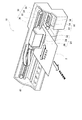
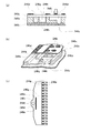
図1は、いわゆるインクジェットプリンタを例に用いて本実施例の液体噴射装置の大まかな構成を示した説明図である。図示されているように、インクジェットプリンタ10は、主走査方向に往復動しながら印刷媒体2上にインクドットを形成するキャリッジ20と、キャリッジ20を往復動させる駆動機構30と、印刷媒体2の紙送りを行うためのプラテンローラ40と、正常に印刷可能なようにメンテナンスを行うメンテナンス機構50などから構成されている。キャリッジ20には、インクを収容したインクカートリッジ26や、インクカートリッジ26が装着されるキャリッジケース22、キャリッジケース22の底面側(印刷媒体2に向いた側)に搭載されてインク滴を吐出するインク吐出ヘッド24などが設けられており、インクカートリッジ26内のインクがインク吐出ヘッド24からインク滴として吐出されて、印刷媒体2上にインクドットが形成されるようになっている。
A. Device configuration :
A-1. Configuration of liquid ejector:
FIG. 1 is an explanatory diagram showing a rough configuration of a liquid ejecting apparatus according to the present embodiment, using a so-called ink jet printer as an example. As illustrated, the
キャリッジ20を往復動させる駆動機構30は、主走査方向に延設されたガイドレール38と、内側に複数の歯形が形成されたタイミングベルト32と、タイミングベルト32の歯形と噛み合う駆動プーリ34と、駆動プーリ34を駆動するためのステップモータ36などから構成されている。タイミングベルト32の一部はキャリッジケース22に固定されており、タイミングベルト32を駆動することによって、ガイドレール38に沿ってキャリッジケース22を移動させることができる。また、タイミングベルト32と駆動プーリ34とは歯形によって互いに噛み合っているので、ステップモータ36で駆動プーリ34を駆動すると、駆動量に応じて精度良くキャリッジケース22を移動させることが可能となっている。
The
印刷媒体2の紙送りを行うプラテンローラ40は、図示しない駆動モータやギア機構によって駆動されて、印刷媒体2を副走査方向に所定量ずつ紙送りすることが可能である。また、メンテナンス機構50は、ホームポジションと呼ばれる印字領域外の領域に設けられており、インク吐出ヘッド24の表面を払拭するワイパーブレード52や、インク吐出ヘッド24に押しつけられてインク吐出ヘッド24との間に密閉空間を形成するキャップ部54、キャップ部54の密閉空間に接続された吸引ポンプ56などから構成されている。印刷を行わないときには、キャリッジ20をホームポジションまで移動させて、ワイパーブレード52でインク吐出ヘッド24の表面を払拭するとともに、キャップ部54を押しつけてインク吐出ヘッド24の表面に密閉空間を形成することによって、インクの乾きを防止する。そして、必要に応じて(あるいは定期的に)吸引ポンプ56を作動させて密閉空間を負圧にすることにより、インク吐出ヘッド24からインクを吸い出す動作(クリーニング動作)を行う。後述するように、必要に応じて(あるいは定期的に)クリーニング動作を行うことにより、正常な印字状態を保つことが可能となっている。
The
A−2.インク吐出ヘッドの構造 :
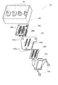
図2は、キャリッジ20に搭載されたインク吐出ヘッド24の構造を示す分解斜視図である。図示されるようにインク吐出ヘッド24は、硬質樹脂によって形成された基台240の下面側に、回路基板242と、硬質樹脂製のヘッドベース244と、流路ユニット246と、ステンレス製の薄板によって形成されたヘッドカバー248とが、取付ネジ249によって共締めされて構成されている。尚、図示が煩雑となることを避けるために、図2では、シール用の部材については表示を省略している。
A-2. Ink discharge head structure:
FIG. 2 is an exploded perspective view showing the structure of the
このうちの流路ユニット246には、複数本の微細なインク流路が形成されており、流路ユニット246の下面側にはインク滴を吐出する微細なノズルが、インク流路毎に設けられている。また、それぞれのインク流路には、インクを加圧してノズルからインク滴を吐出するための圧力室も形成されている。流路ユニット246の詳細な構造については後ほど別図を用いて説明するが、圧力室の上面側は弾性変形可能に構成されており、圧電素子を用いて圧力室の上面側を変形させることによって、圧力室内のインクを加圧することが可能となっている。
Among these, the
回路基板242には圧電素子アセンブリ242pが組み込まれており、この圧電素子アセンブリ242pの先端には、圧力室を変形させてインクを加圧するための圧電素子が取り付けられている。周知のように圧電素子は、電圧を加えると高い応答速度で伸縮する特性を有しており、この特性を利用することで、圧力室内のインクを高い応答速度で加圧して微細なインク滴を吐出することが可能となっている。また、回路基板242には、圧電素子を駆動する電気回路や、回路を構成する各種の電子部品なども搭載されている。
A
ヘッドベース244には、細長い貫通穴244gが設けられており、回路基板242とヘッドベース244とを組み付けると、回路基板242に組み付けられた圧電素子アセンブリ242pが、この貫通穴244gに収容されて、圧電素子アセンブリ242pの先端に設けられた圧電素子が、流路ユニット246の圧力室の上面に接するようになっている。また、ヘッドベース244に設けられた貫通穴244gは、圧電素子が圧力室の上面の適切な位置に適切な角度で接するように圧電素子アセンブリ242pを位置決めする機能も有している。
The
基台240には、インクカートリッジ26からインクを取り込むためのインク取込部241が設けられている。インクカートリッジ26をキャリッジケース22に装着すると、カートリッジ内のインクがインク取込部241から取り込めるようになっている。基台240の内部には、インク取込部241から下面に貫通するインクの通路が設けられており、インク取込部241から流入したインクは、この通路を通って基台240の下面側の開口部から流出する。
The
基台240の直ぐ下方に組み付けられる回路基板242には、基台240内のインクの通路が下面側で開口する位置に、インク通過穴242hが設けられている。また、この回路基板242の直ぐ下方に組み付けられるヘッドベース244にも、インクが通過するインク通路244hが設けられている。このため、インクカートリッジ26を基台240に装着すると、インクカートリッジ26の内部のインクがインク取込部241から取り込まれて、基台240内部に設けられたインクの通路を通過した後、インク通過穴242h、インク通路244hを通って、流路ユニット246に供給されるようになっている。
The
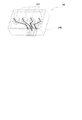
図3は、インク取込部241から取り込まれたインクが、基台240およびヘッドベース244を経由して、流路ユニット246に供給される様子を概念的に示した説明図である。図中に示した太い実線は、基台240内を通過するインクの流路を概念的に表している。また、太い一点鎖線は、ヘッドベース244内を通過するインクの流路を概念的に表している。このように、インク取込部241から取り込まれたインクは、それぞれのインク通路を通って流路ユニット246に供給され、流路ユニット246内で、各ノズルに分配される。以下では、流路ユニット246の構造と、流路ユニット246内で各ノズルにインクが供給される様子について説明する。
FIG. 3 is an explanatory diagram conceptually showing a state in which ink taken in from the ink take-in
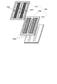
図4は、流路ユニット246の構造を示した分解組立図である。流路ユニット246は、シリコンプレート製のキャビティ246sの上面側および下面側に、それぞれ弾性フィルム製のシート246uと、ステンレス製のノズルプレート246nとを、エポキシ樹脂系の接着剤で接着しながら積層した構造となっている。キャビティ246sには、大きな共通インク通路246gと、後述するインク分配部、共通インク通路246gとインク分配部との間の仕切り壁246k、ノズル毎に設けられた微細な圧力室、更に共通インク通路246gとそれぞれの圧力室とを繋ぐ溝などが、エッチング加工によって形成されている。そして、上面側および下面側にシート246uとノズルプレート246nとを積層することで、共通インク通路246gからノズル毎の圧力室へとインクを供給するインク通路が形成されるようになっている。
FIG. 4 is an exploded view showing the structure of the
シート246uは、ステンレス製の薄い金属泊に、弾性フィルムをラミネート加工で接着することによって形成されている。図4では、ステンレス製の薄膜の部分を、斜線を付すことによって表示している。また、シート246uには、ヘッドベース244からインクが供給される箇所に供給口246hが設けられており、ヘッドベース244を通過したインクは、供給口246hからキャビティ246sの共通インク通路246gに流入した後、共通インク通路246gから、それぞれの圧力室に供給されるようになっている。また、ノズルプレート246nには、各圧力室に対応する位置に1つずつノズル穴が形成されており、このノズル穴からインク滴が吐出される。
The
図5は、流路ユニット246内で、それぞれの圧力室246pにインクが供給される通路の形状を示した説明図である。図5(a)には、インク分配部246d、共通インク通路246g、および圧力室246pの部分で流路ユニット246の断面を取った拡大図が示されている。図5(a)に示されているように、流路ユニット246内には、インク分配部246dや、共通インク通路246g、圧力室246p、ノズル246zなどが設けられており、インク分配部246dと共通インク通路246gとは仕切り壁246kで隔てられ、また、共通インク通路246gと圧力室246pとの間には突起246tが設けられている。供給口246hから流路ユニット246内に流入したインクは、インク分配部246dに供給され、その後、インク分配部246dから共通インク通路246g、更には、圧力室246pへと供給されるようになっている。
FIG. 5 is an explanatory view showing the shape of a passage through which ink is supplied to each
図5(b)は、流路ユニット246の構造を概念的に示した斜視図である。また、図5(c)は、流路ユニット246を上方から見て、内部に形成されているインクの通路を概念的に示した説明図である。図示されているように、インク分配部246dと共通インク通路246gとの間には仕切り壁246kが設けられているが、仕切り壁246kはインク分配部246dと共通インク通路246gとを完全には隔てておらず、インク分配部246dは連通口246oを介して共通インク通路246gと連通した構造となっている。また、共通インク通路246gと圧力室246pとの間には突起246tが設けられているが、共通インク通路246g内に供給されたインクは、突起246tの側方を通って圧力室246p内に流入可能に形成されている。更に、圧力室246pの底面(ノズルプレート246n)には、インク滴を吐出するためのノズル246zが、各圧力室246pに1つずつ設けられている。
FIG. 5B is a perspective view conceptually showing the structure of the
以上に説明したように、本実施例のインクジェットプリンタ10では、キャリッジケース22にインクカートリッジ26を装着すると、インクカートリッジ26内のインクが、インク取込部241を介してインク吐出ヘッド24内に取り込まれ、基台240およびヘッドベース244を通過して、流路ユニット246内に流入する。そして、流路ユニット246内では、先ず、インク分配部246dに流入し、次いで共通インク通路246gに流入して、共通インク通路246gから圧力室246pに流入した後、それぞれの圧力室246pがインクで満たされるようになっている。このように圧力室246pがインクで満たされた状態で、圧力室246pの上面側を押圧すると、圧力室246p内のインクが加圧されて、ノズル246zからインク滴として吐出される。
As described above, in the
本実施例のインクジェットプリンタ10では、圧電素子アセンブリ242pに組み込まれた圧電素子を用いて圧力室246pの上面を押圧しており、この圧電素子アセンブリ242pは、図2に示したように、回路基板242に搭載されている。このように、圧力室246pが形成されている流路ユニット246と、圧電素子が組み込まれている回路基板242とが別部品として構成されていることから、流路ユニット246および圧電素子アセンブリ242pは、ヘッドベース244によって互いに位置決めされた状態で組み付けられるようになっている。しかし、それでも、圧電素子が押圧する位置が、設計上の押圧位置から若干ずれてしまうことも生じ得る。そこで、シート246uには、圧力室246pのほぼ中央にある設計上の押圧位置に、ステンレス製の金属薄膜が設けられている。尚、この金属薄膜の部分は、島246iと呼ばれることがある。前述したように、シート246u自体は弾性フィルムによって形成されているが、島246iの部分は弾性フィルムよりも固いので、圧電素子の押圧位置が多少ずれたとしても、島246i全体で圧力室246pを押圧することになる。その結果、位置ずれによる圧力室246pの変形量の違い、延いてはインク吐出量の違いを吸収することが可能となっている。
In the
尚、以上の説明では、圧力室246p内のインクを加圧する手法として、圧電素子を用いて圧力室246pを変形させる手法を用いた場合について説明した。しかし、圧力室246p内のインクを加圧することが可能であれば、どのような方法を用いても良く、例えば、圧力室内の一部に発熱体を組み込んでおき、発熱体を発熱させることによって、圧力室内のインクを加圧することも可能である。
In the above description, the case where the method of deforming the
最後に、インクを収容したインクカートリッジ26について簡単に説明しておく。図6は、本実施例のインクジェットプリンタ10で用いられるインクカートリッジ26の外観形状を示した斜視図である。図示されるように、インクカートリッジ26は略長方形に形成された箱形の容器であり、底面には、取付孔26hが設けられている。工場からの出荷時には、取付孔26hはフィルムによって封止されており、カートリッジ内のインクが外気に触れないようになっている。そして、インクカートリッジ26をキャリッジケース22に装着すると、取付孔26hを封止していたフィルムを破って、インク取込部241と取付孔26hとが接続され、インクカートリッジ26内のインクがインク吐出ヘッド24側に供給されるようになっている。また、インクカートリッジ26のインクが空になった場合には、インクカートリッジ26毎、新たなものに交換する。
Finally, the
もっとも、インクカートリッジ26を交換する際に、インク取込部241から空気が混入することがある。また、印刷時にキャリッジ20が往復動することによる振動などにより、インクカートリッジ26の装着後にも、少しずつ空気が混入することがある。そして、図2ないし図5を用いて説明したように、インク吐出ヘッド24の内部は極めて微細な構造となっているので、例えば、気泡で共通インク通路246g内が塞がれてしまうと、それより下流側の圧力室246pにはインクが供給されず、インク滴が吐出できなくなってしまうという不具合が発生する。あるいは、圧力室246pに気泡が発生すると、圧電素子で押圧しても気泡が縮むだけでインクは加圧されず、その圧力室246pのノズル246zからはインク滴が吐出できなくなってしまう。そこで、こうした問題の発生を回避するために、定期的に、あるいは必要に応じて、インクと一緒に気泡をノズル246zから強制的に排出させるクリーニング動作が行われる。
However, when the
A−3.クリーニング動作の概要 :
クリーニング動作は、キャリッジ20をホームポジションまで移動させた状態で行われる。図1を用いて説明したように、印刷を行わないときには、印字領域の外側に設けられたホームポジションにキャリッジ20を退避させておき、ホームポジションに設けられたキャップ部54でインク吐出ヘッド24のノズル面を封止して、インクの乾きを防止するようになっている。また、印字領域とホームポジションとの間にはワイパーブレード52が設けられており、キャリッジ20をホームポジションに退避させる際には、インク吐出ヘッド24のノズル面に付着した異物や余分なインクなどを、ワイパーブレード52で拭い取るようになっている。
A-3. Overview of cleaning operation:
The cleaning operation is performed with the
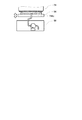
図7は、インク吐出ヘッド24のノズル面をキャップ部54で封止した状態を概念的に表した説明図である。キャップ部54は、図示しないアクチュエータによって上下方向に移動可能に構成されており、キャリッジ20をホームポジションに退避させた後、キャップ部54をノズル面に押しつけると、インク吐出ヘッド24のノズル面とキャップ部54との間に密閉された空間が形成される。これにより、インクの乾きを防止することが可能となる。
FIG. 7 is an explanatory diagram conceptually showing a state in which the nozzle surface of the
また、キャップ部54の下方には吸引ポンプ56が設けられており、吸引ポンプ56の吸い込み口がキャップ部54の内側に開口している。このため、キャップ部54を押しつけた状態で吸引ポンプ56を作動させると、インク吐出ヘッド24のノズル面とキャップ部54との間に形成された空間が負圧となり、ノズル246zからインクが吸い出されて、通常の印刷では生じないような速いインクの流れが発生する。インクに混入した気泡がインク通路の何処かに引っ掛かっている場合でも、このインクの流れに押し流されるようにして、ノズル246zから排出することが可能となる。クリーニング動作では、このようにして、インクを勢いよく吸い出すことにより、インク取込部241からノズル246zまでのインク通路に混入している気泡をインクとともに排出する。
A
もっとも、クリーニング動作では多量のインクを消費するので、できるだけ効率よく気泡を排出可能なことが望ましい。すなわち、1回のクリーニング動作で消費するインク量はできるだけ少ないことが望ましく、また、消費するインク量が同じであれば、できるだけ完全に気泡を排出する方が望ましい。たとえ、1回のクリーニング動作で消費するインク量が同じであっても、クリーニング動作後に残存する気泡の量が少なければ、クリーニング動作の頻度が少なくなるので、結局、インク消費を抑制することが可能である。本実施例のインクジェットプリンタ10では、図5に示したように流路ユニット246内にインク分配部246dを設けることで、効率よいクリーニング動作を実現している。以下では、この点について詳しく説明する。
However, since a large amount of ink is consumed in the cleaning operation, it is desirable that bubbles can be discharged as efficiently as possible. That is, it is desirable that the amount of ink consumed in one cleaning operation is as small as possible. If the amount of ink consumed is the same, it is desirable to discharge bubbles as completely as possible. Even if the amount of ink consumed in a single cleaning operation is the same, if the amount of bubbles remaining after the cleaning operation is small, the frequency of the cleaning operation is reduced, so that it is possible to suppress ink consumption after all. It is. In the
B.クリーニング動作中のインクの流れ :
本実施例のインクジェットプリンタ10では、共通インク通路246gの上流側にインク分配部246dを設けることにより、クリーニング動作中の共通インク通路246g内でのインクの流れを改善して、流路ユニット246内の気泡を効率よく排出することを可能としている。以下では、このようなことが可能な理由について説明するが、その準備として、インク分配部246dを有さない従来の流路ユニット246におけるクリーニング動作中のインクの流れについて簡単に説明しておく。
B. Ink flow during cleaning operation:
In the
B−1.従来の流路ユニットでのインクの流れ :
従来の流路ユニット246では、共通インク通路246gの両端(インクの流れ方向からすると下流側)で通路の幅を狭めることによって、共通インク通路246g内でのインクの流れを改善し、これによって、気泡を排出され易くしている。
B-1. Ink flow in a conventional flow path unit:
In the conventional
図8は、インク分配部246dを有さない従来の流路ユニット246において、共通インク通路246gの両端の通路幅を狭めることにより、気泡が排出され易くなる理由を示した説明図である。図8(a)には、共通インク通路246gの両端で通路幅が狭められていないものとした場合の、流路ユニット246内に形成されるインクの通路が概念的に示されている。そして、図8(b)は、このような形態のインクの通路でクリーニング動作を行ったときに、共通インク通路246g内をインクが流れる様子を概念的に示した説明図である。
FIG. 8 is an explanatory diagram showing the reason why bubbles are easily discharged by narrowing the passage width at both ends of the
インク分配部246dが設けられていない従来の流路ユニット246では、インクが供給口246hから共通インク通路246gに直接供給され、そしてインクは、共通インク通路246g内を流れながら各ノズルで吸引されて外部に排出される。図8(b)には、このときの共通インク通路246g内でのインクの流れ、およびノズル246zからインクが排出される様子が概念的に示されている。クリーニング動作中は、各ノズルから多量のインクが吸引されるから、供給口246hから下流側(共通インク通路246gの両端側)では、インクの流量が不足気味となる。このため、共通インク通路246gの通路幅が同じであれば、流量の低下に伴ってインクの流速が低下してしまい、共通インク通路246gの壁面や圧力室246p内などに気泡が付着している場合でも、インクの流れによって気泡を引き剥がして、ノズル246zから排出することが出来なくなってしまう。
In the conventional
そこで、従来の流路ユニット246では、共通インク通路246gの両端側(供給口246hからのインクの流れで言えば下流側)で通路幅を狭くすることにより、インクの流速を確保している。これにより、付着した気泡をインクの流れによって引き剥がし、ノズル246zからインクとともに外部に排出することを可能としている。図8(c)には、共通インク通路246gの両端側で通路幅が狭くなっている様子が概念的に示されており、また、図8(d)には、通路幅を狭くすることによって、共通インク通路246gの下流側でもインクの流速が確保される様子を概念的に示されている。
Therefore, in the conventional
もっとも、通路幅が狭くなる程、インクの通路抵抗が増加し、通路抵抗が増加すると流速の低下を引き起こす。このため、共通インク通路246gの通路幅を狭めることによってインクの流速を確保する方法では、気泡の排出を容易にする効果にも限界がある。特に、ノズル246zの数が増加して、共通インク通路246gの長さが長くなった場合には、下流側で十分なインク流速を確保することは困難となる。
However, as the passage width becomes narrower, the ink passage resistance increases. When the passage resistance increases, the flow velocity decreases. For this reason, the method of ensuring the ink flow rate by narrowing the passage width of the
図9は、共通インク通路246gが長くなった場合に、両端の通路幅を狭める方法では、通路の下流側でインクの流速を確保することが困難となる理由を示した説明図である。インクの流速を確保するために、共通インク通路246gの通路幅を狭くする方法では、共通インク通路246gが長くなると、その分だけ更に通路幅を狭くしなければならなくなる。その結果、図9に示すように、共通インク通路246gが長くなると両端付近で通路幅が極端に狭くなって通路抵抗が増加してしまい、この部分(図中に破線で囲った部分)でのインク流速を確保することが困難となってしまう。このため、共通インク通路246gの両端での通路幅を狭めてインク流速を確保する方法では、通路内あるいは圧力室内などに付着した気泡を引き剥がして、ノズルから排出する効果に限界があるのである。
FIG. 9 is an explanatory diagram showing the reason why it is difficult to secure the ink flow velocity on the downstream side of the passage by the method of narrowing the passage width at both ends when the
こうした点に鑑みて、本実施例の流路ユニット246では、図5を用いて説明したように、共通インク通路246gの上流側にインク分配部246dを設け、供給口246hから供給されたインクを分配した状態で共通インク通路246gに供給している。こうすることで、クリーニング動作中の共通インク通路246g内でのインクの流れを改善して、通路内あるいは圧力室内などに付着している気泡を引き剥がして、より確実に排出することが可能になるとともに、たとえ共通インク通路246gが長くなった場合でも、気泡を確実に排出することが可能となっている。以下、この点について詳しく説明する。
In view of these points, in the
B−2.本実施例の流路ユニットでのインクの流れ :
図10は、本実施例の流路ユニット246内に形成された通路を流れるインクの流れを概念的に示した説明図である。図10(a)には、流路ユニット246内に形成されたインクの通路が概念的に示されている。図示されているように、本実施例の流路ユニット246においても、共通インク通路246gには複数の圧力室246pが並列に接続されているが、共通インク通路246gの上流側には、仕切り壁246kで隔てられて、インク分配部246dが設けられている。そして、供給口246hから供給されたインクは、インク分配部246dに設けられた2つの連通口246oに分配されて、共通インク通路246gに供給されるようになっている。
B-2. Ink flow in the flow path unit of this example:
FIG. 10 is an explanatory diagram conceptually showing the flow of ink flowing through the passage formed in the
図10(b)には、インク分配部246dに供給されたインクが分配されて、共通インク通路246gに供給される様子が概念的に示されている。図示されているように、共通インク通路246gには、2箇所に設けられた連通口246oからインクが供給されている。このため、共通インク通路246gの両端付近、および両端付近の圧力室246pについても連通口246oからの距離を短くすることができ、途中の圧力室246pで吸引されるインク量が減少し、気泡を引き剥がすために必要なインク流速を確保することができる。その結果、クリーニング動作を行っても気泡が残ってしまう領域を発生させることなく、確実に気泡を排出することが可能となる。
FIG. 10B conceptually shows the state where the ink supplied to the
もちろん、2つの連通口246oの中間付近の圧力室246pについては、インクの経路が長くなった分だけインク流量が減少し、流量の減少は気泡の排出を悪くする方向に作用する。しかし、この領域の圧力室246pは、図8に例示したように、従来の共通インク通路246gの場合には他の圧力室246pに比べてインクの供給経路が極端に短く、従ってインク流量も他の圧力室に比べて多過ぎた状態となっている。すなわち、この領域の圧力室246pのインク流量を抑制することは、多すぎる流量を是正しているのに過ぎず、抑制した分だけ他の圧力室246pへのインク流量を増加させることができる。結局、共通インク通路246g全体としては、気泡がより排出され易いように、インクの流れが改善されていることになる。
Of course, with respect to the
また、インク分配部246dと共通インク通路246gとを連通する連通口246oは、2つに限らず、より多数の連通口246oを設けることとしても良い。例えば、図11(a)に例示したように、3つの連通口246oを設けることとしても良い。この場合でも、インク分配部246dに供給されたインクは、インク分配部246d内で3つの連通口246oに分配された状態で、共通インク通路246gに供給された後、各圧力室246pに供給される。図11(b)には、各圧力室246pにインクが供給される様子が概念的に示されている。このように、3つの連通口246oが設けられている場合でも、各圧力室246pは、最寄りの連通口246oからインクの供給を受けることができる。このため、共通インク通路246g内でインクの流量が不足する部分や、インク流量が不足する圧力室246pが発生することが無く、確実に気泡を排出することが可能となる。
Further, the number of communication ports 246o that allow the
尚、共通インク通路246g内のインクの流れを改善するためには、インク分配部246dは、供給口246hから供給されたインクを複数の連通口246oに分配するようなものであることが望ましい。例えば、図12に例示したように、仕切り壁246kによって隔てられるとともに、3つの連通口「A」、「B」、「C」で共通インク通路246gと連通する部屋を形成したとしても、供給口246hから供給されたインクは大部分が連通口「B」から共通インク通路246gに供給されるので、仕切り壁246kによって隔てられた部屋はインクを分配する機能を実質的には備えていない。このような場合は、インク分配部246dが形成されているとは言えず、従って、共通インク通路246g内のインクの流れを改善する効果を期待することは難しい旨を付言しておく。
In order to improve the flow of ink in the
共通インク通路246gの上流側にインク分配部246dを有する本実施例の流路ユニット246によれば、共通インク通路246gが長くなった場合でも、複数の連通口246oを適切な位置に設けることで、共通インク通路246g内のインクの流れを改善して、確実に気泡を排出することが可能となる。
According to the
図13は、インク分配部246dを設けることで長い共通インク通路246g内でのインクの流れを改善している様子を示した説明図である。図13(a)に示した例では、共通インク通路246gが長くなったことに伴って、より両端の方向に移動させた位置に、連通口246oが設けられている。また、図13(b)には、このような位置に設けられた連通口246oから各圧力室246pにインクが供給される様子が、概念的に示されている。図示されているように、共通インク通路246gが長くなり、インクを供給すべき圧力室246pの数は増えているものの、それぞれの連通口246oについて見れば、インクを供給すべき共通インク通路246gの長さも、圧力室246pの数もそれほど多いわけではない。従って、共通インク通路246g内でインク流量が不足する部分や、インク流量が不足する圧力室246pを発生させることなく、気泡を確実に排出することが可能となる。
FIG. 13 is an explanatory diagram showing a state in which the ink flow in the long
加えて、本実施例では、前述したように、インクの経路が短く、従ってインク流量が多い圧力室246pについてはインク流量を抑制し、その分を他の圧力室246pに回すことで、各圧力室246pのインク流量を均一化する作用も有している。このため、クリーニング動作時に、各ノズル246zから排出するインク流量をいたずらに増加させずとも、共通インク通路246gあるいは圧力室246pなど、流路ユニット246全体の気泡を効率よく排出することが可能となる。
In addition, in the present embodiment, as described above, the ink flow rate is suppressed for the
C.変形例 :
上述した本実施例の流路ユニット246については、種々の変形例を考えることができる。以下では、これらの変形例について簡単に説明する。
C. Modified example:
Various modifications of the
C−1.第1の変形例 :
上述した実施例では、インクが供給される供給口246hの周辺の形状はそのままで、単に仕切り壁246kを追加することによって、インク分配部246dを形成するものとして説明した。こうした方法では、最も簡単にインク分配部246dを形成して、共通インク通路246g内のインクの流れを改善することが可能である。しかし、インク分配部246dの形状がより適したものとなるように、供給口246hの周辺の形状を変更しても良い。
C-1. First modification:
In the above-described embodiment, the shape of the periphery of the
図14は、第1の変形例の流路ユニット246において、より適切な形状に形成されたインク分配部246dを概念的に示した説明図である。図14(a)では、2つの連通口246oが設けられている場合が例示されている。また、図14(b)には、より多数の連通口246oを有する場合が例示されている。図14に示した例は何れも、インク分配部246d内をインクが流れるときのインク分配部246dの断面積が、連通口246oに対して十分な大きさに設定されている。
FIG. 14 is an explanatory diagram conceptually showing the
このようにしておけば、供給口246hから供給されたインクが連通口246oに流れる間に発生する圧力損失(通路抵抗と言い換えることも可能)を最小限に抑制することができるので、連通口246oの大きさによって、それぞれの連通口246oに分配するインク流量を簡単に制御することが可能となる。例えば、連通口246oの大きさを揃えておけば、何れの連通口246oからも同じように共通インク通路246gにインクを供給することができる。その結果、共通インク通路246gの中でインク流量の不足する部分が発生したり、インク流量の不足する圧力室246pが発生することを回避することが可能となり、より確実に気泡を排出することが可能となる。
By doing so, the pressure loss (which can be paraphrased as passage resistance) generated while the ink supplied from the
加えて、インク分配部246d内での圧力損失を最小限に抑制することができるので、供給口246hを設ける位置に大きな自由度を持たせることが可能となる。例えば、図14(b)に示した例では、供給口246hが偏った位置に設けられているため、246hから各連通口246oまでの距離が大きく異なっている。しかし、第1の変形例では、インク分配部246dの流れ方向への断面積が、連通口246oの大きさに対して十分に確保されているので、供給口246hから各連通口246oまでの圧力損失は何れも小さく、従って、何れの連通口246oからも、ほぼ同じ圧力でインクを供給することが可能となる。その結果、インクカートリッジ26から流路ユニット246にインクを供給するための通路の設計自由度を増加させることができ、延いては、インク吐出ヘッド24の設計自由度を増加させることが可能となる。
In addition, since the pressure loss in the
C−2.第2の変形例 :
上述した実施例では、連通口246oの大きさは、共通インク通路246gから圧力室246pにインクを取り込むための取込口(図5に示した突起246tと圧力室246pの側壁との間の開口部)に比べれば、十分に大きいものとして説明した。しかし、圧力室246pへのインクの取込口と同程度(例えば、10倍程度以下の大きさ)の小さな連通口246oを、共通インク通路246gとインク分配部246dとを隔てる仕切り壁246kに多数設けることとしてもよい。
C-2. Second modification:
In the embodiment described above, the size of the communication port 246o is the intake port for taking ink from the
図15は、仕切り壁246kに多数の微細な連通口246oが設けられた第2の変形例を概念的に示した説明図である。図15(a)には、第2の変形例の流路ユニット246内に形成されるインクの通路が概念的に示されており、図15(b)には、第2の変形例の流路ユニット246内に形成された通路をインクが流れる様子が概念的に示されている。また、図15(c)には、仕切り壁246kに多数の微細な連通口246oが形成された様子を表す斜視図が示されている。
FIG. 15 is an explanatory diagram conceptually showing a second modification in which a number of fine communication ports 246o are provided in the
このような微細な連通口246oは通路抵抗となるので、図15(b)に示されているように、インクは仕切り壁246kに沿って共通インク通路246gの両端まで行き渡り、全ての連通口246oから万遍なく圧力室246pにインクを供給することが可能となる。
Since such a fine communication port 246o serves as a passage resistance, as shown in FIG. 15B, the ink spreads along the
特に、連通口246oの大きさを、共通インク通路246gから圧力室246pにインクを取り込むための取込口(図5に示した突起246tと圧力室246pの側壁との間の開口部)よりも小さくしておけば、インクカートリッジ26からノズル246zまでのインクの通路全体として見たときの通路抵抗を低減することも可能となる。すなわち、インクに混入した異物が、共通インク通路246gから圧力室246pにインクを取り込むための取込口を詰まらせると、インク滴が吐出不能となってしまうため、こうした事態を避けるべく、インク通路の上流側(代表的には、図2に示したインク取込部241と基台240との間)には、目の細かなフィルタが設けられている。そして、圧力室246pにインクを取り込むための取込口よりも大きな異物は、フィルタで除去された後、流路ユニット246内に供給されるようになっている。
In particular, the size of the communication port 246o is larger than the intake port (the opening between the
しかし、連通口246oの大きさを、圧力室246pに設けられた取込口よりも小さくしておけば、取込口を詰まらせるような異物は連通口246oで除去することができるので、上流側に設けたフィルタを省略することが可能となる。加えて、図15(b)に示されているように、連通口246oは共通インク通路246gの全長に亘って設けることができるので、十分な濾過面積を確保することができ、上流側に設けられているフィルタよりも通過抵抗を小さなものとすることができる。このため、インクの通路全体としての通路抵抗を低減することも可能となる。
However, if the size of the communication port 246o is made smaller than that of the intake port provided in the
C−3.第3の変形例 :
また、上述した各種の実施例では、流路ユニット246内のインクの通路は、シリコンプレートをエッチング処理して形成されたキャビティ246sによって主に形成され、ノズル246zは、ステンレス製のノズルプレート246nに形成されているものとして説明した。しかし、図5に示したように、仕切り壁246kを設ける関係上、共通インク通路246gの部分はハーフエッチング処理(その部分が貫通するまでエッチング処理を行うのではなく、底部を残した状態で中断するエッチング処理)されることが多い。このような場合には、圧力室246pの部分もハーフエッチング処理することで底面を形成し、ノズル246zの部分だけ貫通させてもよい。
C-3. Third modification:
Further, in the various embodiments described above, the ink passage in the
こうすれば、キャビティ246sとノズルプレート246nとを一体で形成することができるので、部品点数が低減できて製造効率を向上させることが可能となるとともに、部品の組み付け誤差が混入する可能性も排除することができる。
In this way, the
更に加えて、上述した第2の変形例のように、圧力室246pの取込口よりも小さな連通口246oを仕切り壁246kに多数設けた場合には、インクカートリッジ26からノズル246zまでの全体の通路抵抗を低減させることができるので、これを活用して、次のような大きな利点を得ることも可能となる。すなわち、全体としてのインクの通路抵抗が小さくなるので、この分だけ、共通インク通路246g(およびインク分配部246d)を薄くすることができる。現状の流路ユニット246では、全体としてのインクの通路抵抗を抑えるために、共通インク通路246gの断面積を確保する必要があり、そのため、図5あるいは図15などに示したように、共通インク通路246gと圧力室246pのインク取込口との間に段差が発生している。そして、このような段差の部分ではインクの流れが滞り易く、気泡が溜まり易くなっている。
In addition, in the case where a large number of communication ports 246o smaller than the intake port of the
しかし、圧力室246pのインク取込口よりも小さな連通口246oを仕切り壁246kに多数も受けることで、全体としての通路抵抗を低下させることができれば、その分だけ、共通インク通路246gを薄くすることができるので、共通インク通路246gと圧力室246pの取込口との段差を縮小(あるいは解消)することが可能となる。
However, if the overall passage resistance can be reduced by receiving a large number of communication ports 246o smaller than the ink intake port of the
図16は、共通インク通路246gと圧力室246pの取込口との段差が解消された第3の変形例を例示した説明図である。図示した例では、共通インク通路246gと圧力室246pのインク取込口との間には、何らの段差も発生していない。このため、クリーニング動作を行うことで、気泡を確実に排出することが可能となる。
FIG. 16 is an explanatory diagram illustrating a third modification in which a step between the
C−4.第4の変形例 :
以上に説明した実施例では、インク分配部246dは、何れも流路ユニット246内に設けられているものとして説明した。すなわち、流路ユニット246にインクを供給する供給口246hは、インクカートリッジ26毎に1つずつ設けられており、インクは供給口246hから流路ユニット246内に供給された後、流路ユニット246内に形成されたインク分配部246dで分配されて、共通インク通路246gに供給されるものとして説明した。しかし、インク分配部246dは、共通インク通路246gと複数の連通口246oで連通するとともに、インクを分配して共通インク通路246gに供給するのであれば、必ずしも流路ユニット246内に設けられている必要はない。
C-4. Fourth modification:
In the embodiment described above, the
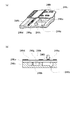
図17は、このような第4の変形例におけるインク分配部246dを概念的に示した説明図である。図示した例では、ヘッドベース244の底面に、溝状のインク分配部246dが形成されている。尚、図17では、図示が煩雑化することを避けるために、貫通穴244gや、インク通路244hの一部については図示が省略されている。
FIG. 17 is an explanatory diagram conceptually showing the
図2を用いて前述したように、ヘッドベース244の底面には流路ユニット246が組み付けられるので、ヘッドベース244の底面に設けられた溝の部分にインク分配部246dが形成される。そして、流路ユニット246の上面側(すなわち、シート246u)には、インク分配部246dが形成される部分の複数箇所に、インクを供給する供給口246hが設けられており、インクカートリッジ26から供給されたインクは、インク分配部246dで分配されて、各供給口246hから流路ユニット246内の共通インク通路246gに流入する。このように、第4の変形例では、流路ユニット246にインクを供給する供給口246hが、そのままインク分配部246dと共通インク通路246gとを連通させる連通口246oとなっている。
As described above with reference to FIG. 2, since the
このような第4の変形例においては、インクを供給する供給口246hを追加するだけで、流路ユニット246の内部については大きな構造変更が不要であり、また、ヘッドベース244についても底面側に溝を追加するだけでよい。このため、従来のヘッドベース244や流路ユニット246を流用しながら、クリーニング動作中に確実に気泡を排出させることが可能となる。
In such a fourth modification, only the
以上、本実施例の印刷装置について説明したが、本発明は上記すべての実施例に限られるものではなく、その要旨を逸脱しない範囲において種々の態様で実施することが可能である。 Although the printing apparatus of the present embodiment has been described above, the present invention is not limited to all the embodiments described above, and can be implemented in various modes without departing from the spirit of the present invention.
10…インクジェットプリンタ、 20…キャリッジ、
22…キャリッジケース、 24…インク吐出ヘッド、
26…インクカートリッジ、 26h…取付孔、 30…駆動機構、
32…タイミングベルト、 40…プラテンローラ、
50…メンテナンス機構、 54…キャップ部、 56…吸引ポンプ、
240…基台、 240f…フィルタ、 241…インク取込部、
242…回路基板、 242h…インク通過穴、
242p…圧電素子アセンブリ、 244…ヘッドベース、
244g…貫通穴、 244h…インク通路、 246…流路ユニット、
246d…インク分配部、 246g…共通インク通路、 246h…供給口、 246i…島、 246k…仕切り壁、 246n…ノズルプレート、
246o…連通口、246p…圧力室、 246s…キャビティ、
246t…突起、 246u…シート、 246z…ノズル
10 ... Inkjet printer, 20 ... Carriage,
22 ... Carriage case, 24 ... Ink discharge head,
26 ... Ink cartridge, 26h ... Mounting hole, 30 ... Drive mechanism,
32 ... Timing belt, 40 ... Platen roller,
50 ... Maintenance mechanism, 54 ... Cap part, 56 ... Suction pump,
240 ... base, 240f ... filter, 241 ... ink intake part,
242 ... Circuit board, 242h ... Ink passage hole,
242p: Piezoelectric element assembly, 244: Head base,
244g ... through hole, 244h ... ink passage, 246 ... flow path unit,
246d: Ink distribution part, 246g: Common ink passage, 246h ... Supply port, 246i ... Island, 246k ... Partition wall, 246n ... Nozzle plate,
246o ... Communication port, 246p ... Pressure chamber, 246s ... Cavity,
246t ... projection, 246u ... sheet, 246z ... nozzle
Claims (4)
前記複数のノズル毎に設けられ、前記液体を加圧することによって下流側のノズルから液体を噴射させる圧力室と、
複数の前記圧力室が並列に接続されて、該圧力室の各々に前記液体を供給する共通液体通路と、
前記共通液体通路に複数箇所の連通口で連通し、前記液体収容容器からの液体を、該複数の連通口に分配して該共通液体通路へと供給する液体分配供給部と
を備える液体噴射装置。 A liquid ejecting apparatus that ejects liquid in a liquid storage container in which liquid is stored from a plurality of nozzles,
A pressure chamber that is provided for each of the plurality of nozzles, and injects liquid from a nozzle on the downstream side by pressurizing the liquid;
A plurality of pressure chambers connected in parallel, and a common liquid passage for supplying the liquid to each of the pressure chambers;
A liquid ejecting apparatus comprising: a liquid distribution supply unit that communicates with the common liquid passage through a plurality of communication ports, distributes the liquid from the liquid storage container to the plurality of communication ports, and supplies the liquid to the common liquid passage. .
前記液体分配供給部は、前記共通液体通路と仕切り部材によって隔てられ、該共通液体通路と並行して設けられた通路である液体噴射装置。 The liquid ejecting apparatus according to claim 1,
The liquid ejecting apparatus, wherein the liquid distribution supply unit is a passage that is separated from the common liquid passage by a partition member and is provided in parallel with the common liquid passage.
前記液体分配供給部は、前記複数の連通口の中で最も大きな連通口よりも大きな断面積を有する通路である液体噴射装置。 The liquid ejecting apparatus according to claim 2,
The liquid ejecting apparatus, wherein the liquid distribution supply unit is a passage having a larger cross-sectional area than a largest communication port among the plurality of communication ports.
前記液体分配供給部と前記共通液体通路とを隔てる仕切り部材は、前記圧力室が前記共通液体通路から前記液体を取り込む取込口よりも小さな複数の前記連通口が形成された部材である液体噴射装置。 The liquid ejecting apparatus according to claim 2,
The partition member that separates the liquid distribution supply unit and the common liquid passage is a member in which the pressure chamber is a member in which a plurality of communication ports smaller than intake ports for taking in the liquid from the common liquid passage are formed. apparatus.
Priority Applications (1)
| Application Number | Priority Date | Filing Date | Title |
|---|---|---|---|
| JP2007041855A JP2008201069A (en) | 2007-02-22 | 2007-02-22 | Liquid jetting apparatus |
Applications Claiming Priority (1)
| Application Number | Priority Date | Filing Date | Title |
|---|---|---|---|
| JP2007041855A JP2008201069A (en) | 2007-02-22 | 2007-02-22 | Liquid jetting apparatus |
Publications (2)
| Publication Number | Publication Date |
|---|---|
| JP2008201069A true JP2008201069A (en) | 2008-09-04 |
| JP2008201069A5 JP2008201069A5 (en) | 2009-12-17 |
Family
ID=39779032
Family Applications (1)
| Application Number | Title | Priority Date | Filing Date |
|---|---|---|---|
| JP2007041855A Withdrawn JP2008201069A (en) | 2007-02-22 | 2007-02-22 | Liquid jetting apparatus |
Country Status (1)
| Country | Link |
|---|---|
| JP (1) | JP2008201069A (en) |
Cited By (5)
| Publication number | Priority date | Publication date | Assignee | Title |
|---|---|---|---|---|
| JP2011140145A (en) * | 2010-01-06 | 2011-07-21 | Seiko Epson Corp | Liquid ejecting head and liquid ejecting apparatus |
| JP2011156805A (en) * | 2010-02-02 | 2011-08-18 | Seiko Epson Corp | Liquid ejecting head and liquid ejecting apparatus |
| JP2014061712A (en) * | 2013-11-21 | 2014-04-10 | Seiko Epson Corp | Liquid injecting head and liquid injecting apparatus |
| JP2015063142A (en) * | 2014-12-25 | 2015-04-09 | セイコーエプソン株式会社 | Liquid jet head and liquid discharge device |
| EP3263341A1 (en) * | 2016-06-30 | 2018-01-03 | Brother Kogyo Kabushiki Kaisha | Liquid ejection head |
Citations (5)
| Publication number | Priority date | Publication date | Assignee | Title |
|---|---|---|---|---|
| JPH0252745A (en) * | 1988-08-17 | 1990-02-22 | Seiko Epson Corp | Ink-jet head |
| JPH09262980A (en) * | 1996-03-29 | 1997-10-07 | Citizen Watch Co Ltd | Ink-jet head |
| JPH11123826A (en) * | 1997-10-23 | 1999-05-11 | Canon Inc | Ink-jet head, and production thereof |
| JP2001058402A (en) * | 1999-08-20 | 2001-03-06 | Brother Ind Ltd | Ink-jet head |
| JP2001058404A (en) * | 1999-08-20 | 2001-03-06 | Brother Ind Ltd | Ink-jet head and manufacture of ink-jet head |
-
2007
- 2007-02-22 JP JP2007041855A patent/JP2008201069A/en not_active Withdrawn
Patent Citations (5)
| Publication number | Priority date | Publication date | Assignee | Title |
|---|---|---|---|---|
| JPH0252745A (en) * | 1988-08-17 | 1990-02-22 | Seiko Epson Corp | Ink-jet head |
| JPH09262980A (en) * | 1996-03-29 | 1997-10-07 | Citizen Watch Co Ltd | Ink-jet head |
| JPH11123826A (en) * | 1997-10-23 | 1999-05-11 | Canon Inc | Ink-jet head, and production thereof |
| JP2001058402A (en) * | 1999-08-20 | 2001-03-06 | Brother Ind Ltd | Ink-jet head |
| JP2001058404A (en) * | 1999-08-20 | 2001-03-06 | Brother Ind Ltd | Ink-jet head and manufacture of ink-jet head |
Cited By (7)
| Publication number | Priority date | Publication date | Assignee | Title |
|---|---|---|---|---|
| JP2011140145A (en) * | 2010-01-06 | 2011-07-21 | Seiko Epson Corp | Liquid ejecting head and liquid ejecting apparatus |
| JP2011156805A (en) * | 2010-02-02 | 2011-08-18 | Seiko Epson Corp | Liquid ejecting head and liquid ejecting apparatus |
| JP2014061712A (en) * | 2013-11-21 | 2014-04-10 | Seiko Epson Corp | Liquid injecting head and liquid injecting apparatus |
| JP2015063142A (en) * | 2014-12-25 | 2015-04-09 | セイコーエプソン株式会社 | Liquid jet head and liquid discharge device |
| EP3263341A1 (en) * | 2016-06-30 | 2018-01-03 | Brother Kogyo Kabushiki Kaisha | Liquid ejection head |
| US10046565B2 (en) | 2016-06-30 | 2018-08-14 | Brother Kogyo Kabushiki Kaisha | Liquid ejection head having flow passages |
| US10464323B2 (en) | 2016-06-30 | 2019-11-05 | Brother Kogyo Kabushiki Kaisha | Liquid ejection head having flow passages |
Similar Documents
| Publication | Publication Date | Title |
|---|---|---|
| JP6428791B2 (en) | Liquid discharge head, liquid discharge unit, and apparatus for discharging liquid | |
| JP5668482B2 (en) | Liquid ejecting head and liquid ejecting apparatus | |
| EP3456541B1 (en) | Liquid ejecting apparatus and control method of liquid ejecting apparatus | |
| CN110461612B (en) | Fluid ejection device and method of operating a fluid ejection device | |
| CN109484032B (en) | Liquid ejecting head, method of manufacturing the same, liquid ejecting apparatus, and piezoelectric device | |
| JP6066263B2 (en) | Droplet discharge head and image forming apparatus | |
| JP2011088400A (en) | Liquid ejector | |
| US8061813B2 (en) | Liquid ejecting head and liquid ejecting apparatus | |
| JP2008201069A (en) | Liquid jetting apparatus | |
| JP2013193445A (en) | Liquid droplet discharging apparatus, and image forming apparatus | |
| JP2004001366A (en) | Liquid ejection head and liquid ejector | |
| JP2009178951A (en) | Liquid jet head and liquid jet device | |
| JP6213815B2 (en) | Droplet discharge head and image forming apparatus | |
| JP2006069168A (en) | Liquid injection apparatus | |
| JP2012143923A (en) | Head and apparatus for ejecting liquid | |
| JP5958795B2 (en) | Ink jet head and image forming apparatus | |
| CN111347787B (en) | Liquid ejecting apparatus and supply system | |
| JP2008179071A (en) | Liquid injection device | |
| TWI399301B (en) | Fluid ejection device | |
| JP2018140599A (en) | Liquid ejecting apparatus and cleaning method | |
| US20090058969A1 (en) | Droplet ejecting device having flow adjusting member | |
| JP2008238414A (en) | Liquid ejection head | |
| JP2014019128A (en) | Droplet discharge head and image forming apparatus | |
| JP2012224052A (en) | Liquid injection head and liquid injection device | |
| JP2012071498A (en) | Liquid ejection head unit |
Legal Events
| Date | Code | Title | Description |
|---|---|---|---|
| A521 | Written amendment |
Effective date: 20091028 Free format text: JAPANESE INTERMEDIATE CODE: A523 |
|
| A621 | Written request for application examination |
Effective date: 20091028 Free format text: JAPANESE INTERMEDIATE CODE: A621 |
|
| A131 | Notification of reasons for refusal |
Free format text: JAPANESE INTERMEDIATE CODE: A131 Effective date: 20110927 |
|
| A521 | Written amendment |
Free format text: JAPANESE INTERMEDIATE CODE: A523 Effective date: 20111125 |
|
| A131 | Notification of reasons for refusal |
Effective date: 20111220 Free format text: JAPANESE INTERMEDIATE CODE: A131 |
|
| A761 | Written withdrawal of application |
Effective date: 20120217 Free format text: JAPANESE INTERMEDIATE CODE: A761 |