JP2008200412A - Storage container and washstand - Google Patents
Storage container and washstand Download PDFInfo
- Publication number
- JP2008200412A JP2008200412A JP2007042452A JP2007042452A JP2008200412A JP 2008200412 A JP2008200412 A JP 2008200412A JP 2007042452 A JP2007042452 A JP 2007042452A JP 2007042452 A JP2007042452 A JP 2007042452A JP 2008200412 A JP2008200412 A JP 2008200412A
- Authority
- JP
- Japan
- Prior art keywords
- plate
- groove
- storage
- shelf
- recess
- Prior art date
- Legal status (The legal status is an assumption and is not a legal conclusion. Google has not performed a legal analysis and makes no representation as to the accuracy of the status listed.)
- Withdrawn
Links
Images


Landscapes
- Assembled Shelves (AREA)
Abstract
Description
本発明は収納庫並びに洗面化粧台に関し、さらに詳細には、鏡の奥に設けられた収納スペースをより有効に使用できる収納庫、並びに、当該収納庫を化粧台として備える洗面化粧台に関する。 The present invention relates to a storage and a vanity, and more particularly to a storage that can use the storage space provided in the back of a mirror more effectively, and a vanity that includes the storage as a vanity.
従来より、棚板の位置を自在に変えることができる収納庫が広く普及しており、収納機能付きのミラーキャビネットを有する三面鏡タイプの洗面化粧台等に応用されている。当該収納庫の一般的な構造は、例えば特許文献1に開示されている。この構造を応用した一般的な三面鏡タイプの洗面化粧台では、三面鏡の裏側に収納スペースとなる凹部が設けられ、それぞれの鏡に対応する3つの空間に分割されている。各空間には着脱可能な棚板が備えられており、棚位置の高さを変更することができる。これにより、収納する物品の高さに応じて棚位置を自由に変えることができる。一方、幅方向に関しては鏡の幅に合わせた縦壁があり、幅方向のサイズを変更することはできない。したがって、横長の物品を収納したい場合には、立てて置く以外に対応する手段がない。
しかし、鏡の裏側の収納スペースに横長の物品を収納したいという要望もあり、従来の洗面化粧台の収納構造の改良が望まれている。本発明の目的は、収納スペースのサイズをより自由に変更できる収納庫、並びに、当該収納庫を備えた洗面化粧台を提供することにある。 However, there is also a desire to store a horizontally long article in the storage space on the back side of the mirror, and an improvement in the storage structure of a conventional vanity is desired. An object of the present invention is to provide a storage room in which the size of the storage space can be changed more freely, and a bathroom vanity equipped with the storage room.
上記した課題を解決するための請求項1に記載の発明は、前面に開口する凹部が設けられた収納庫本体と、前記凹部の開口部分を開閉自在に覆う扉板とを有する収納庫であって、前記収納庫本体は前記凹部の奥壁から手前方向に伸びる棒状の支持部材を複数有し、前記支持部材には板状の部材の端部が係合可能な溝が設けられ、当該溝を介して相互の支持部材間に前記板状の部材を支持可能であることを特徴とする収納庫である。 The invention described in claim 1 for solving the above-described problem is a storage having a storage body provided with a recess opening on the front surface, and a door plate that covers the opening of the recess so as to be opened and closed. The storage body has a plurality of rod-like support members extending in the front direction from the back wall of the recess, and the support member is provided with a groove that can be engaged with an end of a plate-like member. It is a storage characterized by being able to support the said plate-shaped member between mutual support members via.
本発明の収納庫は、収納スペースとして機能する凹部が収納庫本体に設けられており、扉板が当該凹部の開口部分を開閉自在に覆うものである。そして、本発明の収納庫では、収納庫本体が凹部の奥壁から手前方向に伸びる棒状の支持部材を複数有しており、当該支持部材には板状の部材の端部が係合可能な溝が設けられ、当該溝を介して相互の支持部材間に前記板状の部材を支持可能である。本発明の収納庫では、前記したような棒状の支持部材を採用しているので、従来技術のように、固定された縦壁を備える必要がない。すなわち、支持部材間に板状の部材を別途設けることにより、所望の位置に縦壁に相当する部材を設けることができる。本発明の収納庫によれば、収納スペースのサイズを高さ方向のみならず、幅方向にも変更することができる。 In the storage of the present invention, a recess functioning as a storage space is provided in the storage body, and the door plate covers the opening of the recess so as to be freely opened and closed. In the storage of the present invention, the storage body has a plurality of rod-like support members extending in the front direction from the back wall of the recess, and the end of the plate-like member can be engaged with the support member. A groove is provided, and the plate-like member can be supported between the support members via the groove. In the storage of the present invention, since the rod-shaped support member as described above is employed, it is not necessary to provide a fixed vertical wall as in the prior art. That is, by separately providing a plate-like member between the support members, a member corresponding to the vertical wall can be provided at a desired position. According to the storage of the present invention, the size of the storage space can be changed not only in the height direction but also in the width direction.
請求項2に記載の発明は、請求項1に記載の収納庫において、前記凹部の内周壁には板状の部材の端部が係合可能な溝が設けられ、支持部材に設けられた溝と凹部の内周壁に設けられた溝とを介して内周壁と支持部材との間に前記板状の部材を支持可能であることを特徴とする。 According to a second aspect of the present invention, in the storage according to the first aspect, the inner peripheral wall of the concave portion is provided with a groove that can be engaged with an end portion of a plate-like member, and the groove provided in the support member And the plate-like member can be supported between the inner peripheral wall and the support member via a groove provided in the inner peripheral wall of the recess.
本発明の収納庫では、凹部の内周壁にも溝が設けられており、内周壁と支持部材との間に前記板状の部材を支持可能である。かかる構成により、より高い自由度をもって収納スペースのサイズを変更することができる。なお、内周壁は左側壁、右側壁、上壁、および下壁の4面からなる。 In the storage of the present invention, a groove is also provided in the inner peripheral wall of the recess, and the plate-like member can be supported between the inner peripheral wall and the support member. With this configuration, the size of the storage space can be changed with a higher degree of freedom. The inner peripheral wall is composed of four surfaces, a left side wall, a right side wall, an upper wall, and a lower wall.
請求項3に記載の発明は、請求項1又は2に記載の収納庫において、前記板状の部材は、垂直方向に設置される仕切り板であることを特徴とする。 According to a third aspect of the present invention, in the storage according to the first or second aspect, the plate-like member is a partition plate installed in a vertical direction.
かかる構成により、幅方向のサイズをより高い自由度をもって変更することができる。 With this configuration, the size in the width direction can be changed with a higher degree of freedom.
請求項4に記載の発明は、請求項1又は2に記載の収納庫において、前記板状の部材は、水平方向に設置される棚板であることを特徴とする。 According to a fourth aspect of the present invention, in the storage according to the first or second aspect, the plate-like member is a shelf plate installed in a horizontal direction.
かかる構成により、高さ方向のサイズもより高い自由度をもって変更することができる。 With this configuration, the size in the height direction can be changed with a higher degree of freedom.
請求項5に記載の発明は、請求項3に記載の収納庫において、前記仕切り板はその側面に板状の部材の端部が係合可能な溝が設けられたものであり、当該仕切り板に設けられた溝を介して相互の仕切り板間に板状の棚板を支持可能であることを特徴とする。 According to a fifth aspect of the present invention, in the storage according to the third aspect, the partition plate is provided with a groove that can engage an end portion of a plate-like member on a side surface thereof. A plate-like shelf board can be supported between the partition plates via a groove provided in the board.
本発明の収納庫では、仕切り板間にも板状の棚板を支持可能であるので、高さ方向のサイズをさらに高い自由度をもって変更することができる。 In the storage of this invention, since a plate-shaped shelf board can be supported also between partition plates, the size of a height direction can be changed with a still higher degree of freedom.
請求項6に記載の発明は、請求項3に記載の収納庫において、前記仕切り板はその側面に板状の部材の端部が係合可能な溝が設けられたものであり、前記凹部の側壁には板状の部材の端部が係合可能な溝が設けられ、凹部の側壁に設けられた溝と仕切り板に設けられた溝とを介して側壁と仕切り板との間に板状の棚板を支持可能であることを特徴とする。
The invention according to
本発明の収納庫では、側壁と仕切り板との間にも板状の棚板を支持可能であるので、高さ方向のサイズをさらに高い自由度をもって変更することができる。 In the storage of the present invention, a plate-shaped shelf board can be supported between the side wall and the partition plate, so that the size in the height direction can be changed with a higher degree of freedom.
請求項7に記載の発明は、請求項1〜6のいずれか1項に記載の収納庫において、前記支持部材は、凹部の奥壁と一体的に形成されていることを特徴とする。
The invention according to
かかる構成により、凹部の収納スペースをより有効に活用でき、強度的にも優れた収納庫が提供される。 With such a configuration, the storage space of the concave portion can be used more effectively, and a storage room having excellent strength can be provided.
請求項8に記載の発明は、請求項1〜7のいずれか1項に記載の収納庫からなる化粧台が洗面台の上部に設置され、前記扉板の表面に鏡が設けられていることを特徴とする洗面化粧台である。 As for invention of Claim 8, the dressing table which consists of a storage of any one of Claims 1-7 is installed in the upper part of a wash-stand, and the mirror is provided in the surface of the said door plate. It is a vanity table characterized by.
本発明は洗面化粧台に係るものであり、上述した本発明の収納庫を化粧台として備えるものである。本発明の洗面化粧台によれば、鏡の裏(すなわち扉板の裏)の収納スペースをより有効に使うことができる。 The present invention relates to a vanity, and includes the above-described storage of the present invention as a vanity. According to the vanity of the present invention, the storage space behind the mirror (that is, the back of the door plate) can be used more effectively.
本発明の収納庫によれば、収納スペースのサイズを高さ方向のみならず、幅方向にも変更することができ、収納スペースをより有効に使うことができる。 According to the storage of the present invention, the size of the storage space can be changed not only in the height direction but also in the width direction, and the storage space can be used more effectively.
本発明の洗面化粧台についても同様であり、鏡の裏の収納スペースをより有効に使うことができる。 The same applies to the vanity of the present invention, and the storage space behind the mirror can be used more effectively.
以下、本発明の実施形態について、洗面化粧台を例として説明する。なお、以下の説明において、上下、左右、手前・奥は洗面化粧台の正面に立った使用者から見た方向を指すものとする。図1は、本発明の実施形態に係る洗面化粧台の外観を示す斜視図である。図2は、図1の洗面化粧台における化粧台本体を示す正面図である。図3は、凹部内における支持部材の設置状態を示す斜視図である。図4は、支持部材を示す斜視図である。図5は、仕切り板を示す斜視図である。図6は、中央棚部を示す斜視図である。図7は、仕切り板と棚部を取り付けた状態における化粧台本体を示す正面図である。図8は、仕切り板と棚部を取り付けた状態の他の例における化粧台本体を示す正面図である。 Hereinafter, an embodiment of the present invention will be described using a vanity as an example. In the following description, the top, bottom, left, right, front, and back indicate directions viewed from the user standing in front of the vanity. FIG. 1 is a perspective view showing an appearance of a vanity according to an embodiment of the present invention. FIG. 2 is a front view showing a dressing table body in the vanity table of FIG. FIG. 3 is a perspective view showing an installation state of the support member in the recess. FIG. 4 is a perspective view showing the support member. FIG. 5 is a perspective view showing the partition plate. FIG. 6 is a perspective view showing the central shelf. FIG. 7 is a front view showing the dressing table main body with the partition plate and the shelf attached. FIG. 8 is a front view showing a dressing table main body in another example in which a partition plate and a shelf are attached.
図1に示す洗面化粧台1は、洗面台2と化粧台(収納庫)3とからなる。洗面台2は、シンク5、カラン6、収納部7を備えた一般的なものである。
A vanity table 1 shown in FIG. 1 includes a vanity table 2 and a vanity table (storage) 3. The
化粧台3は洗面台2の上に設置されている。化粧台3は、化粧台本体(収納庫本体)10の前面に中央鏡15および左右のサイド鏡16,17からなる三面鏡が設けられたものである。三面鏡の上部であって化粧台本体10の前面には照明装置18が設けられている。また、右サイド鏡17の下方には、スイッチ類19が設置されており、照明スイッチや後述する曇り止め用電熱線のスイッチ並びに電源コンセント等が配置されている。
The dressing table 3 is installed on the
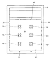
図2に示す様に、化粧台本体10には物品を収納できる凹部25が設けられ、前面に向かって開口している。従来技術の洗面化粧台では、凹部25が中央鏡15と左右のサイド鏡16,17の幅に合わせた3つの空間に分けられたものが多いが、本実施形態では凹部25は基本的に1つの空間からなる。そして、中央鏡15と左右のサイド鏡16,17とをもって、凹部25の開口22が覆われている。より具体的には、中央鏡15は扉板21の表面に装着されており、扉板21が開閉自在に凹部25の開口22の中央部分を覆っている。左右のサイド鏡16,17についても左右の扉板(図示せず)に装着されており、凹部25の開口22の左右部分を覆っている。
As shown in FIG. 2, the dressing table
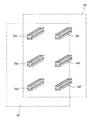
図2,3に示す様に、本実施形態の洗面化粧台1では、凹部25内に6本の棒状の支持部材12a〜12fが設けられている。支持部材12a〜12fは凹部25の奥壁23と一体的に形成されており、奥から手前に向かって(開口22に向かって)に伸びている。
As shown in FIGS. 2 and 3, in the vanity 1 of the present embodiment, six rod-
互いに水平方向に位置する1組の支持部材12同士(支持部材12aと12b、12cと12d、並びに、12eと12f)の距離は、凹部25の側壁から各支持部材12までの水平方向の距離(左側壁から支持部材12a,12c,12eまでの距離、並びに、右側壁から支持部材12b,12d,12fまでの距離)よりも大きい。これは、互い水平方向に位置する1組の支持部材12同士の距離が中央鏡15の幅に対応し、凹部25の側壁から各支持部材12までの水平方向の距離が左右のサイド鏡16,17の幅にそれぞれ対応するためである。
The distance between the pair of
図3,4に示す様に、支持部材12は棒状の部材であり、より具体的には四角柱状の部材である。支持部材12の各側面には溝13が設けられている。溝13は四角状に削られた形状を有しており、支持部材12の一端から他端にかけて連続的に形成されている。1本の支持部材12には計4個の溝13が設けられている。
As shown in FIGS. 3 and 4, the
図2に示す様に、凹部25の内周壁にも溝24,43が設けられている。溝24は凹部25の左右の側壁に7個ずつ、計14個設けられている。溝24は、支持部材12の溝13と同じ形状とサイズを有するものであり、溝13と同じ高さの位置ならびにそれらの中間位置に設けられている。一方、溝43は凹部25の上壁と下壁に2個ずつ、計4個設けられている。溝43も溝13と同じ形状とサイズを有するものであり、溝13と同じ幅方向の位置に設けられている。
As shown in FIG. 2,
凹部25内には、仕切り板27(図5)、中央棚部(棚板)33(図6)、及びサイド棚部(棚板)53が設置される。仕切り板27は、互いに垂直方向に位置する1組の支持部材12同士(支持部材12aと12c、12cと12e、12bと12d、並びに、12dと12f)あるいは支持部材12と上下壁との間(上壁と支持部材12a,12bとの間、並びに、下壁と支持部材12e,12fとの間)に設置されるものである。仕切り板27は、図5に示す様な形状を有する板状の部材であり、溝28と突起30を有する。溝28は仕切り板27の両側面に設けられており、その形状とサイズは支持部材12の溝13と全く同じである。一方、突起30は仕切り板27の上端部分と下端部分とから構成されている。すなわち、仕切り板27の上下の端部をもって突起30が1個ずつ形成されている。突起30の短手方向の幅と支持部材12の溝13の幅とは略同じであり、突起30は溝13に係合可能である。
In the
仕切り板27の縦方向のサイズは、互いに垂直方向に位置する1組の支持部材12同士(支持部材12aと12c、12cと12e、12bと12d、並びに、12dと12f)の溝13に突起30を嵌め込んだ場合に、これらの支持部材12間にちょうど嵌るサイズである。
The size of the
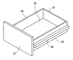
一方、互いに水平方向に位置する1組の支持部材12同士(支持部材12aと12b、12cと12d、並びに、12eと12f)の間(中央鏡15に対応する位置)には、中央棚部(棚板)33が設置可能である。図6に示す様に、中央棚部33は、底板35と側面板36と正面板37によって構成されている。中央棚部33はトレイとして機能し、底板35に物品を載置可能である。中央棚部33の2個の側面板36には、それぞれ突起38が長手方向全体に設けられている。すなわち、中央棚部33の幅方向の両端部に突起38が1個ずつ設けられている。突起38の短手方向の幅と、支持部材12の溝13の幅ならびに仕切り板27の溝28の幅とは略同じであり、突起38は溝13ならびに溝28に係合可能である。
On the other hand, between the pair of
中央棚部33の幅方向のサイズは、互いに水平方向に位置する1組の支持部材12同士(支持部材12aと12b、12cと12d、並びに、12eと12f)の溝13に突起38を嵌め込んだ場合に、支持部材12間にちょうど嵌るサイズである。これは、仕切り板27を支持部材12に嵌め込み、左右に配置された1組の仕切り板27の溝28に突起38を嵌め込んだ場合に、仕切り板27の間にちょうど嵌るサイズでもある。
The size of the
支持部材12a,12c,12eと左側壁との間(左のサイド鏡16に対応する位置)、並びに支持部材12b,12d,12fと右側壁との間(右のサイド鏡17に対応する位置)には、サイド棚部53(図7,8参照)が設置可能である。サイド棚部53の構成は、中央棚部33の構成と基本的に同じであり、幅方向のサイズが異なるのみである。すなわち、支持部材12の溝13と側壁の溝24に、側面に設けられた突起を嵌め込んだ場合に、支持部材12と凹部25の側壁との間にちょうど嵌るサイズである。これは、仕切り板27を支持部材12に嵌め込み、仕切り板27の溝28と側壁の溝24に側面に設けられた突起を嵌め込んだ場合に、仕切り板27と凹部25の側壁との間にちょうど嵌るサイズでもある。
Between the
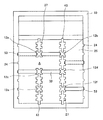
本実施形態において、仕切り板27、中央棚部33、及びサイド棚部53はかなり高い自由度をもって化粧台本体10の凹部25内に設置することができる。図7に示す例では、7個の仕切り板27と、2個の中央棚部33と、4個のサイド棚部53とを設置している。図7の空間Aは、支持部材12aと12cとの間に仕切り板27をあえて設けないことにより形成されており、幅方向に広い空間となっている。空間Aを利用することにより、横長の物品を収納することができる。もちろん、全ての中央棚部33とサイド棚部53は着脱可能であり、所望の垂直位置に設置することができる。また、仕切り板27を所望の位置に組み直すことにより、所望の幅方向のサイズを有する空間を形成することができる。
In this embodiment, the
図8に示す例では、8個の仕切り板27と、2個の中央棚部33と、4個のサイド棚部53とを設置している。この例では、仕切り板27を設置可能な8箇所全てに設置しているので、従来の洗面化粧台で採用されている縦壁を有する構成に近い。しかし、この例でも仕切り板27を所望の位置に組み直すことにより、所望の幅方向のサイズを有する空間を形成することができる。
In the example shown in FIG. 8, eight
上記した実施形態では、凹部25が中央鏡15と左右のサイド鏡16,17とをもって覆われているが、凹部25が中央鏡15のみによって覆われるものでもよい。この場合には、中央鏡15の奥にある収納スペースのみが、そのサイズを高さ方向や幅方向に自由に変更できるものとなる。なおこの場合には、左右のサイド鏡16,17の奥には収納スペースを設けてもよいし、設けなくてもよい。
In the above-described embodiment, the
上記した実施形態では、仕切り板として図5に示す仕切り板27のような溝28を有するものを採用しているが、仕切り板は溝を有しない単なる板体でもよい。この場合には、仕切り板間や仕切り板と側壁との間には棚部を設置することができないが、支持部材12間ならびに支持部材12と側壁との間に棚部を設けることができる。
In the above-described embodiment, a partition plate having a
1 洗面化粧台
2 洗面台
3 化粧台(収納庫)
10 化粧台本体(収納庫本体)
12 支持部材
13 溝
15 中央鏡(鏡)
16 左サイド鏡(鏡)
17 右サイド鏡(鏡)
21 扉板
22 開口
23 奥壁
24 溝
25 凹部
27 仕切り板
28 溝
30 突起
33 中央棚部(棚板)
38 突起
43 溝
53 サイド棚部(棚板)
1
10 Vanity body (storage body)
12 Supporting
16 Left side mirror (mirror)
17 Right side mirror (mirror)
21
38
Claims (8)
Priority Applications (1)
| Application Number | Priority Date | Filing Date | Title |
|---|---|---|---|
| JP2007042452A JP2008200412A (en) | 2007-02-22 | 2007-02-22 | Storage container and washstand |
Applications Claiming Priority (1)
| Application Number | Priority Date | Filing Date | Title |
|---|---|---|---|
| JP2007042452A JP2008200412A (en) | 2007-02-22 | 2007-02-22 | Storage container and washstand |
Publications (1)
| Publication Number | Publication Date |
|---|---|
| JP2008200412A true JP2008200412A (en) | 2008-09-04 |
Family
ID=39778486
Family Applications (1)
| Application Number | Title | Priority Date | Filing Date |
|---|---|---|---|
| JP2007042452A Withdrawn JP2008200412A (en) | 2007-02-22 | 2007-02-22 | Storage container and washstand |
Country Status (1)
| Country | Link |
|---|---|
| JP (1) | JP2008200412A (en) |
Citations (4)
| Publication number | Priority date | Publication date | Assignee | Title |
|---|---|---|---|---|
| JPS49116319U (en) * | 1973-02-01 | 1974-10-04 | ||
| JPH04354902A (en) * | 1991-05-31 | 1992-12-09 | Natl House Ind Co Ltd | Rack structure |
| JPH0619580U (en) * | 1992-05-27 | 1994-03-15 | サンウエーブ工業株式会社 | Mounting structure for shelves, etc. |
| JPH07124024A (en) * | 1993-11-02 | 1995-05-16 | Noritz Corp | Dressing mirror unit |
-
2007
- 2007-02-22 JP JP2007042452A patent/JP2008200412A/en not_active Withdrawn
Patent Citations (4)
| Publication number | Priority date | Publication date | Assignee | Title |
|---|---|---|---|---|
| JPS49116319U (en) * | 1973-02-01 | 1974-10-04 | ||
| JPH04354902A (en) * | 1991-05-31 | 1992-12-09 | Natl House Ind Co Ltd | Rack structure |
| JPH0619580U (en) * | 1992-05-27 | 1994-03-15 | サンウエーブ工業株式会社 | Mounting structure for shelves, etc. |
| JPH07124024A (en) * | 1993-11-02 | 1995-05-16 | Noritz Corp | Dressing mirror unit |
Similar Documents
| Publication | Publication Date | Title |
|---|---|---|
| JP2008200412A (en) | Storage container and washstand | |
| JP2013000384A (en) | Kitchen cabinet | |
| JP6193580B2 (en) | Partition storage structure | |
| JP7417890B2 (en) | drawer | |
| JP6288817B2 (en) | Article storage unit, fixture system | |
| KR20130051593A (en) | Self assembly storage goods for drawer | |
| KR20170089590A (en) | Corner-mounted folding type dressing table | |
| CN218219597U (en) | Beautiful makeup washing articles for use store frame | |
| WO2021084966A1 (en) | Drawer | |
| JP2003213820A (en) | Partition wall | |
| JP2007054542A (en) | Washstand | |
| JP2010167103A (en) | Mirror support with outlet | |
| JP2008081974A (en) | Structure for residential floor change | |
| KR20180002245U (en) | Dressing table attached with a chair | |
| JP2023142122A (en) | Wash stand | |
| JP2017080152A (en) | Wiring structure in cabinet and washstand having the same | |
| JP2008200411A (en) | Washstand | |
| JP2896852B2 (en) | Partition panel | |
| KR200200827Y1 (en) | Mirror stand | |
| JP2005000229A (en) | Mirrored basin cabinet | |
| JP5294040B2 (en) | Bathroom vanity | |
| JP2011162961A (en) | Partition device and partition system | |
| JP2019072379A (en) | Furniture with mirror | |
| JP2011072483A (en) | Cabinet having storage | |
| JP2022169159A (en) | storage cabinet |
Legal Events
| Date | Code | Title | Description |
|---|---|---|---|
| A621 | Written request for application examination |
Free format text: JAPANESE INTERMEDIATE CODE: A621 Effective date: 20090728 |
|
| A977 | Report on retrieval |
Free format text: JAPANESE INTERMEDIATE CODE: A971007 Effective date: 20110121 |
|
| A131 | Notification of reasons for refusal |
Free format text: JAPANESE INTERMEDIATE CODE: A131 Effective date: 20110125 |
|
| A761 | Written withdrawal of application |
Free format text: JAPANESE INTERMEDIATE CODE: A761 Effective date: 20110325 |