JP2008195475A - Earthquake resistant passenger conveyor device for building - Google Patents

Earthquake resistant passenger conveyor device for building Download PDF

Info

Publication number
JP2008195475A
JP2008195475A JP2007030691A JP2007030691A JP2008195475A JP 2008195475 A JP2008195475 A JP 2008195475A JP 2007030691 A JP2007030691 A JP 2007030691A JP 2007030691 A JP2007030691 A JP 2007030691A JP 2008195475 A JP2008195475 A JP 2008195475A
Authority
JP
Japan
Prior art keywords
building
passenger conveyor
section
horizontal section
bent portion
Prior art date
Legal status (The legal status is an assumption and is not a legal conclusion. Google has not performed a legal analysis and makes no representation as to the accuracy of the status listed.)
Granted
Application number
JP2007030691A
Other languages
Japanese (ja)
Other versions
JP5284590B2 (en
Inventor
Chuichi Saito
忠一 斎藤
Mayumi Fukuyama
満由美 福山
Atsushi Hayashi
篤 林
Hajime Yoshida
一 吉田
Current Assignee (The listed assignees may be inaccurate. Google has not performed a legal analysis and makes no representation or warranty as to the accuracy of the list.)
Hitachi Ltd
East Japan Railway Co
Original Assignee
Hitachi Ltd
East Japan Railway Co
Priority date (The priority date is an assumption and is not a legal conclusion. Google has not performed a legal analysis and makes no representation as to the accuracy of the date listed.)
Filing date
Publication date
Application filed by Hitachi Ltd, East Japan Railway Co filed Critical Hitachi Ltd
Priority to JP2007030691A priority Critical patent/JP5284590B2/en
Publication of JP2008195475A publication Critical patent/JP2008195475A/en
Application granted granted Critical
Publication of JP5284590B2 publication Critical patent/JP5284590B2/en
Active legal-status Critical Current
Anticipated expiration legal-status Critical

Links

Images

Abstract

<P>PROBLEM TO BE SOLVED: To provide an earthquake resistant passenger conveyor device for a building capable of improving earthquake resistance of the building. <P>SOLUTION: An upper end of a framework 5 of the passenger conveyor is fixed to a strength member 3, which is provided in the building 4, through a coupling means 16, and a lower end of the framework 5 is fixed to the ground 2 through a fixing means. With this structure, the passenger conveyor 1 can restrict vibration of the building 4 in earthquake till the passenger conveyor 1 is broken, and as a result, an earthquake resistant passenger conveyor device for a building capable of improving earthquake resistance of the building 4 can be obtained. <P>COPYRIGHT: (C)2008,JPO&amp;INPIT

Description

本発明はエスカレーターや傾斜型電動道路等の乗客コンベアを設置して建築物の耐震性を向上させる建築物耐震用の乗客コンベア装置に係り、特に、乗客コンベアを地盤から傾斜して建築物に設置して建築物の耐震性を向上させる建築物耐震用の乗客コンベア装置に関する。   The present invention relates to a passenger conveyor device for building earthquake resistance that installs passenger conveyors such as escalators and inclined electric roads to improve the earthquake resistance of the building, and in particular, the passenger conveyor is installed on the building inclined from the ground. It is related with the passenger conveyor apparatus for building earthquake resistance which improves the earthquake resistance of a building.

従来の乗客コンベア装置において、地震時の建築物の揺れに対しては、例えば特許文献1に示すような対策が講じられている。即ち、地震時の建築物の揺れによる離れた階床間の距離の拡大変位によって乗客コンベア装置が落下しないように、乗客コンベア装置と階床との間に滑動部を設けたものである。   In a conventional passenger conveyor device, for example, a countermeasure as shown in Patent Document 1 is taken against shaking of a building during an earthquake. That is, a sliding part is provided between the passenger conveyor device and the floor so that the passenger conveyor device does not fall due to an enlarged displacement of the distance between the separated floors due to the shaking of the building during the earthquake.

特開2001−158585号公報JP 2001-158585 A

上記特許文献1に開示の技術は、乗客コンベア装置に対する対策であり、乗客コンベア装置が設置された建築物が耐震構造となっていることが前提の技術である。そのため、地震時の際、乗客コンベア装置の落下に対しての対策を講じても、建築物が揺れによって損傷しては意味のない対策となる。   The technique disclosed in Patent Document 1 is a countermeasure against the passenger conveyor device, and is based on the premise that the building in which the passenger conveyor device is installed has an earthquake-resistant structure. Therefore, even if measures are taken against the fall of the passenger conveyor device during an earthquake, it is meaningless if the building is damaged by shaking.

本発明の目的は、建築物に対する耐震性を向上し得る建築物耐震用の乗客コンベア装置を提供することにある。   The objective of this invention is providing the passenger conveyor apparatus for building earthquake resistance which can improve the earthquake resistance with respect to a building.

上記目的を達成する為に本発明は、乗客コンベアの枠体の上端部を建築物に設けられた強度部材に連結手段を介して固定すると共に、この枠体の下端部を地盤に形成したピット内に固定手段を介して固定したのである。   In order to achieve the above object, the present invention provides a pit in which the upper end of a passenger conveyor frame is fixed to a strength member provided in a building via a connecting means, and the lower end of the frame is formed on the ground. It was fixed through fixing means.

以上説明したように、乗客コンベアの枠体の上端部を建築物に固定し、下端部を地盤に固定することで、建築物の地震時の揺れに対して乗客コンベアが損傷されるまで抑制することができ、その結果、建築物の耐震性を向上し得る建築物耐震用の乗客コンベア装置を得ることができるのである。   As described above, the upper end of the passenger conveyor frame is fixed to the building, and the lower end is fixed to the ground, so that the passenger conveyor is suppressed against shaking during an earthquake of the building. As a result, it is possible to obtain a passenger conveyor device for building earthquake resistance that can improve the earthquake resistance of the building.

以下本発明による建築物耐震用の乗客コンベア装置の第1の実施の形態を図1〜図5に示すエスカレーター装置について説明する。ここに示すエスカレーター装置1は、駅舎のホーム(地盤)2と、ホーム2から支持体3を介して支持された橋上通路(建築物)4間に跨って設置されるものである。   A first embodiment of a passenger conveyor device for building earthquake resistance according to the present invention will be described below with reference to an escalator device shown in FIGS. The escalator device 1 shown here is installed across a platform (ground) 2 of a station building and a bridge passage (building) 4 supported from the platform 2 via a support 3.

そして、エスカレーター装置1は、地盤であるホーム2の床面2Fと建築物である橋上通路4の床面4Fに跨って、枠体5を設置している。   And the escalator apparatus 1 has installed the frame 5 across the floor surface 2F of the platform 2 which is the ground, and the floor surface 4F of the bridge passage 4 which is a building.

この枠体5は、図5に示すように、左右一対の側枠6A,6Bと、これら側枠6A,6Bを連結する連結梁7とを備えている。そして前記側枠6A,6Bは、長手方向に延在する上弦材8A,8Bと、この上弦材8A,8Bの下方に間隔をおいて配置された下弦材9A,9Bと、これら上弦材8A,8Bと下弦材9A,9Bとを連結する連結部材10A,10Bとを備えている。   As shown in FIG. 5, the frame 5 includes a pair of left and right side frames 6A and 6B and a connecting beam 7 that connects the side frames 6A and 6B. The side frames 6A and 6B include upper chord members 8A and 8B extending in the longitudinal direction, lower chord members 9A and 9B disposed below the upper chord members 8A and 8B, and the upper chord members 8A and 8B. 8B and lower chord members 9A and 9B are provided with connecting members 10A and 10B.

このように構成された枠体5は、図4に示すように、傾斜区間L1と、この傾斜区間L1の上端部に連なる上水平区間L2と、傾斜区間L1の下端部に連なる下水平区間L3とを有している。   As shown in FIG. 4, the frame 5 configured in this manner includes an inclined section L1, an upper horizontal section L2 continuous with the upper end of the inclined section L1, and a lower horizontal section L3 continuous with the lower end of the inclined section L1. And have.

このように構成された枠体5の下水平区間L3は、前記ホーム2に設けたピット2P内に収納され、その端部を床面2Fの近傍に係合し、上水平区間L2の端部は橋上通路4の床面4Fの近傍に係合している。そして、このような枠体5内には無端状に連結された複数の踏板11が図示しない駆動手段によって回動できるように案内されている。この踏板11の両側に沿った前記側枠6A,6Bには、夫々欄干パネル12が立設され、この欄干パネル12の周縁に沿って前記踏板11と同期して駆動される移動手摺13が案内されている。   The lower horizontal section L3 of the frame body 5 thus configured is housed in the pit 2P provided in the home 2, and its end is engaged in the vicinity of the floor surface 2F, and the end of the upper horizontal section L2 Is engaged in the vicinity of the floor surface 4F of the bridge passage 4. In such a frame body 5, a plurality of step plates 11 connected endlessly are guided so as to be rotated by a driving means (not shown). A balustrade panel 12 is erected on each of the side frames 6A and 6B along both sides of the tread board 11, and a moving handrail 13 driven in synchronization with the tread board 11 is guided along the periphery of the balustrade panel 12. Has been.

このように構成された枠体5の上端部、具体的には、枠体5の傾斜区間L1の上端部を、強度部材である前記橋上通路4の支持体3に、連結手段であるワイヤロープ16を介して連結している。詳細には、枠体5の傾斜区間L1における左右一対の下弦材9A,9Bの上端部に跨って連結座17を固定し、この連結座17と前記支持体3に夫々アイボルト18A,18Bを連結し、これらアイボルト18A,18B間にワイヤロープ16を通して張力を加えたものである。尚、ワイヤロープ16の代わりにチェーンや連結棒を用いてもよい。   The upper end of the frame body 5 configured as described above, specifically, the upper end portion of the inclined section L1 of the frame body 5 is connected to the support body 3 of the bridge passage 4 which is a strength member as a wire rope as a connecting means. 16 are connected. Specifically, the connecting seat 17 is fixed across the upper ends of the left and right lower chord members 9A and 9B in the inclined section L1 of the frame body 5, and the eyebolts 18A and 18B are connected to the connecting seat 17 and the support body 3, respectively. A tension is applied through the wire rope 16 between the eyebolts 18A and 18B. In place of the wire rope 16, a chain or a connecting rod may be used.

さらに、枠体5の下端部、具体的には、枠体5の傾斜区間L1の下端部でホーム2に設けたピット2P内に収納された部分を、固定具19に固定している。さらに詳しく説明すると、図3に示すように、ピット2P内に、枠体5の傾斜区間L1と同じ傾斜の取付け面19Sを有する固定具19を固定し、この取付け面19Sと対向する枠体5の傾斜区間L1の下端に固定座20を設け、これら固定座20と取付け面19Sとをボルトやナットあるいは溶接等の周知の固定手段21で固定している。   Furthermore, the lower portion of the frame 5, specifically, the portion housed in the pit 2 </ b> P provided in the home 2 at the lower end of the inclined section L <b> 1 of the frame 5 is fixed to the fixture 19. More specifically, as shown in FIG. 3, a fixture 19 having a mounting surface 19S having the same inclination as the inclined section L1 of the frame 5 is fixed in the pit 2P, and the frame 5 facing the mounting surface 19S is fixed. A fixed seat 20 is provided at the lower end of the inclined section L1, and the fixed seat 20 and the mounting surface 19S are fixed by a known fixing means 21 such as a bolt, a nut, or welding.

以上説明したように、エスカレーター装置1の枠体5の上端部を支持体3に連結手段(16,18A,18B)を介して連結し、枠体5の下端部を固定手段21を介してホーム2に固定することで、地震時に橋上通路4が揺れようとしても、その揺れはエスカレーター装置1の枠体5が強度部材となって抑制される。その結果、橋上通路4の耐震性は向上する。   As described above, the upper end of the frame 5 of the escalator device 1 is connected to the support 3 via the connecting means (16, 18A, 18B), and the lower end of the frame 5 is connected to the home via the fixing means 21. By fixing to 2, even if the bridge passage 4 tries to sway during an earthquake, the swaying is suppressed by the frame 5 of the escalator device 1 being a strength member. As a result, the earthquake resistance of the bridge passage 4 is improved.

ところで、上記実施の形態においては、震度が小さい地震時には、エスカレーター装置1によって建築物(橋上通路4)の揺れにある程度耐えるが、震度が大きい地震時には、建築物(橋上通路4)の揺れを抑制することで、エスカレーター装置1の枠体5には大きな力が作用し、枠体5を変形させようとする。   By the way, in the above-described embodiment, the escalator device 1 withstands the shaking of the building (bridge passage 4) to some extent by the escalator device 1 when the seismic intensity is low. By doing so, a large force acts on the frame body 5 of the escalator device 1 and tries to deform the frame body 5.

このように、エスカレーター装置1の枠体5には大きな力が作用することが十分に予想される場合には、図6及び図7の第1変形例に示すように、枠体5を補強すればよい。尚、図1〜図5と同符号は、同一構成部品を示すので、再度の詳細な説明は省略する。   As described above, when a large force is expected to act on the frame 5 of the escalator device 1, the frame 5 is reinforced as shown in the first modification of FIGS. 6 and 7. That's fine. The same reference numerals as those in FIGS. 1 to 5 indicate the same components, and thus detailed description thereof is omitted.

即ち、建築物(橋上通路4)の揺れによって圧縮力や引張力が集中し易い枠体5の上屈曲部P1と下屈曲部P2とを、上水平区間L2から傾斜区間L1の一部にかけて上補強板22A,22Bを設けると共に、下水平区間L3から傾斜区間L1の一部にかけて下補強板23A,23Bを設けるのである。   That is, the upper bent portion P1 and the lower bent portion P2 of the frame body 5 where compressive force and tensile force tend to concentrate due to the shaking of the building (bridge passage 4) are extended from the upper horizontal section L2 to a part of the inclined section L1. The reinforcing plates 22A and 22B are provided, and the lower reinforcing plates 23A and 23B are provided from the lower horizontal section L3 to a part of the inclined section L1.

これら上補強板22A,22B及び下補強板23A,23Bは、各側枠6A,6Bの幅寸法Wを超えてエスカレーター装置1の構成部品の設置に支障が生じては問題となるので、図7に示すように、上弦材8A,8B及び下弦材9A,9Bの幅寸法W内に位置するように、上弦材8A,8B及び下弦材9A,9Bと略同じ厚さの板材を用いている。   The upper reinforcing plates 22A and 22B and the lower reinforcing plates 23A and 23B exceed the width dimension W of the side frames 6A and 6B, which causes a problem in the installation of the components of the escalator device 1. As shown in FIG. 4, plate materials having substantially the same thickness as the upper chord members 8A, 8B and the lower chord members 9A, 9B are used so as to be positioned within the width dimension W of the upper chord members 8A, 8B and the lower chord members 9A, 9B.

そして、上補強板22A,22Bと下補強板23A,23Bは、高さ方向に延在して上弦材8A,8Bの下縁と下弦材9A,9Bの上縁に跨って溶接して連結されると共に、必要に応じて、連結部材10A,10Bにも溶接により連結されている。   The upper reinforcing plates 22A and 22B and the lower reinforcing plates 23A and 23B extend in the height direction and are connected by welding over the lower edges of the upper chord members 8A and 8B and the upper edges of the lower chord members 9A and 9B. In addition, it is connected to the connecting members 10A and 10B by welding as necessary.

このように、枠体5の上屈曲部P1と下屈曲部P2を補強することで、地震によって橋上通路4が大きく横揺れしようとしても、その圧縮力や引張力による曲げに対して上屈曲部P1と下屈曲部P2は変形することはない。その結果、エスカレーター装置1の枠体5によって橋上通路4の横揺れを防止することができ、橋上通路4の耐震性を向上させることができる。逆を云えば、エスカレーター装置1によって橋上通路4の耐震性が向上するので、橋上通路4の支持体3は、垂直荷重を重点に設計をすればよく、したがって、支持体3の設計施工を簡単にすることが可能となる。   In this way, by reinforcing the upper bent portion P1 and the lower bent portion P2 of the frame body 5, even if the bridge passage 4 is about to roll due to an earthquake, the upper bent portion is bent against the bending due to the compressive force or tensile force. P1 and the lower bent portion P2 are not deformed. As a result, the rolling of the bridge passage 4 can be prevented by the frame 5 of the escalator device 1, and the earthquake resistance of the bridge passage 4 can be improved. In other words, since the escalator device 1 improves the earthquake resistance of the bridge passage 4, the support body 3 of the bridge passage 4 has only to be designed with emphasis on the vertical load. Therefore, the design and construction of the support body 3 can be simplified. It becomes possible to.

さらに、枠体5の上水平区間L2と下水平区間L3を建築物である橋上通路4に連結及び固定せずに、枠体5の傾斜区間L1の上下端部を建築物である橋上通路4の支持体3及びホーム2に直接連結及び固定することで、上水平区間L2と下水平区間L3には橋上通路4の横揺れに起因する圧縮力や引張力が作用することがなくなり、したがって、枠体5の上屈曲部P1及び下屈曲部P2には大きな曲げ応力は作用しなくなる。その結果、場合によっては上補強板22A,22Bの機械的強度を下げたり、あるいは省略したりすることが可能となる。   Furthermore, without connecting and fixing the upper horizontal section L2 and the lower horizontal section L3 of the frame 5 to the bridge passage 4 that is a building, the upper and lower ends of the inclined section L1 of the frame 5 are the bridge passage 4 that is a building. By directly connecting and fixing to the support body 3 and the home 2, the upper horizontal section L 2 and the lower horizontal section L 3 are not affected by the compressive force or tensile force due to the rolling of the bridge passage 4. Large bending stress does not act on the upper bent portion P1 and the lower bent portion P2 of the frame 5. As a result, the mechanical strength of the upper reinforcing plates 22A and 22B can be lowered or omitted depending on circumstances.

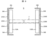
図8及び図9は、枠体5の第2変形例を示すもので、枠体5の上下端部を橋上通路4及びホーム2に連結及び固定するための補強構成であり、図1〜図7に示す符号と同一符号は同一構成部品を示すので、再度の詳細な説明は省略する。   8 and 9 show a second modification of the frame body 5, which is a reinforcing configuration for connecting and fixing the upper and lower ends of the frame body 5 to the bridge passage 4 and the platform 2, and FIG. The same reference numerals as those shown in FIG. 7 indicate the same components, and thus detailed description thereof is omitted.

第2変形例において、第1の実施の形態と異なる構成は、夫々の側枠6A,6Bの傾斜区間L1における上補強板22A,22Bと下補強板23A,23Bで補強された以外の部分をさらに補強して建築物の耐震性を向上させるものである。   In the second modification, the configuration different from that of the first embodiment is that portions other than those reinforced by the upper reinforcing plates 22A and 22B and the lower reinforcing plates 23A and 23B in the inclined sections L1 of the side frames 6A and 6B, respectively. It is further reinforced to improve the earthquake resistance of the building.

即ち、上補強板22A,22Bと下補強板23A,23Bで補強された以外の傾斜区間L1の各側枠6A,6Bにおいて、上弦材8A,8B及び下弦材9A,9Bの下縁及び上縁に、上縁側中間補強板24A,24Bと下縁側中間補強板25A,25Bを、上補強板22A,22B及び下補強板23A,23Bと同じ方法で連結したのである。   That is, in the side frames 6A and 6B of the inclined section L1 other than those reinforced by the upper reinforcing plates 22A and 22B and the lower reinforcing plates 23A and 23B, the lower and upper edges of the upper chord members 8A and 8B and the lower chord members 9A and 9B. In addition, the upper edge side intermediate reinforcing plates 24A and 24B and the lower edge side intermediate reinforcing plates 25A and 25B are connected in the same manner as the upper reinforcing plates 22A and 22B and the lower reinforcing plates 23A and 23B.

このように、上縁側中間補強板24A,24Bと下縁側中間補強板25A,25Bを、上弦材8A,8B及び下弦材9A,9Bの下縁及び上縁に連結することで、上弦材8A,8B及び下弦材9A,9Bの断面積が結果的に増加したこととなる。   In this way, by connecting the upper edge side intermediate reinforcing plates 24A, 24B and the lower edge side intermediate reinforcing plates 25A, 25B to the lower and upper edges of the upper chord members 8A, 8B and the lower chord members 9A, 9B, the upper chord member 8A, As a result, the cross-sectional areas of 8B and the lower chord members 9A and 9B are increased.

その結果、上弦材8A,8B及び下弦材9A,9Bの傾斜区間L1における強度を向上させることができるのは勿論のこと、上屈曲部P1及び下屈曲部P2も上補強板22A,22Bと下補強板23A,23Bで補強できるので、さらに圧縮力と引張力に強い枠体5を得ることができ、建築物(橋上通路4)の耐震性をさらに向上させることができる。   As a result, it is possible to improve the strength of the upper chord members 8A and 8B and the lower chord members 9A and 9B in the inclined section L1, and the upper bent portion P1 and the lower bent portion P2 also have the upper reinforcing plates 22A and 22B and the lower portions. Since it can reinforce with the reinforcing plates 23A and 23B, it is possible to obtain the frame 5 that is more resistant to compressive force and tensile force, and to further improve the earthquake resistance of the building (bridge passage 4).

図10は、図8及び図9をさらに変形させた枠体5の第3変形例を示すもので、図1〜図9に示す符号と同一符号は同一構成部品を示すので、再度の詳細な説明は省略する。   FIG. 10 shows a third modification of the frame 5 that is a further modification of FIG. 8 and FIG. 9, and the same reference numerals as those shown in FIGS. Description is omitted.

この第3変形例においては、枠体5の上屈曲部P1の圧縮力に対する強度をさらに向上させる構成として、上屈曲部P1の内側に、上水平区間L2における下弦材9A,9Bと傾斜区間L1における下弦材9A,9Bとに跨って、補強梁26を設け、この補強梁26と下弦材9A,9Bとの間を補助補強板27で塞ぐか、上補強板22A,22Bを補強梁26まで延在させて補強梁26と下弦材9A,9Bとの間を塞ぐようにしたものである。   In the third modified example, as a configuration for further improving the strength against the compressive force of the upper bent portion P1 of the frame 5, the lower chord members 9A and 9B and the inclined section L1 in the upper horizontal section L2 are provided inside the upper bent section P1. A reinforcing beam 26 is provided to straddle the lower chord members 9A and 9B, and the auxiliary beam 27 is closed between the reinforcing beam 26 and the lower chord members 9A and 9B, or the upper reinforcing plates 22A and 22B are extended to the reinforcing beam 26. It extends so as to close the space between the reinforcing beam 26 and the lower chord members 9A and 9B.

このように、補強梁26を設けることで、枠体5に圧縮力が作用して上屈曲部P1を内側に曲げようとしても、補強梁26及び補助補強板27さらには上補強板22A,22Bによってその曲げに対抗することができ、結果的に、枠体5の強度を向上させて建築物の揺れを抑制することができる。   Thus, by providing the reinforcing beam 26, even if the compressive force acts on the frame 5 and the upper bent portion P1 is bent inward, the reinforcing beam 26, the auxiliary reinforcing plate 27, and the upper reinforcing plates 22A and 22B. Therefore, the bending can be counteracted, and as a result, the strength of the frame 5 can be improved and the shaking of the building can be suppressed.

図11は、本発明による建築物耐震用の乗客コンベア装置の第2の実施の形態を示すもので、図1〜図10に示す符号と同一符号は同一構成部品を示すので、再度の詳細な説明は省略する。   FIG. 11 shows a second embodiment of a passenger conveyor device for building earthquake resistance according to the present invention. The same reference numerals as those shown in FIG. 1 to FIG. Description is omitted.

本実施の形態は、枠体5の上水平区間L2の端部における左右一対の側枠6A,6Bに跨って、連結座28を設けると共に、この連結座28と橋上通路4の強度梁29とに夫々アイボルト18A,18Bを設け、これらアイボルト18A,18B間を連結具30で連結したものである。   In the present embodiment, a connecting seat 28 is provided across the pair of left and right side frames 6A and 6B at the end of the upper horizontal section L2 of the frame 5, and the connecting seat 28 and the strength beam 29 of the bridge passage 4 are provided. Eyebolts 18A and 18B are provided respectively, and the eyebolts 18A and 18B are connected by a connector 30.

即ち、第1の実施の形態は、枠体5の傾斜区間L1における上端部の下方と支持体3との間をワイヤロープ16で連結したものであるが、第2の実施の形態においては、枠体5の上水平区間L2の端部と強度部材である橋上通路4の強度梁29との間を連結具30で連結したものであり、第1の実施の形態と同等の効果を奏することができる。   That is, in the first embodiment, the lower portion of the upper end portion in the inclined section L1 of the frame body 5 and the support body 3 are connected by the wire rope 16, but in the second embodiment, The end portion of the upper horizontal section L2 of the frame 5 and the strength beam 29 of the bridge passage 4 that is a strength member are connected by a connecting tool 30, and the same effect as that of the first embodiment is achieved. Can do.

尚、第2の実施の形態においても、建築物の規模に応じて、枠体5に、上補強板22A,22B、下補強板23A,23B、上縁側中間補強板24A,24B、下縁側中間補強板25A,25B、補強梁26、補助補強板27を全て備えたり、選択的に備えたりすることは可能である。   In the second embodiment, the upper reinforcement plates 22A and 22B, the lower reinforcement plates 23A and 23B, the upper edge side intermediate reinforcement plates 24A and 24B, and the lower edge side intermediate are also attached to the frame 5 according to the scale of the building. The reinforcing plates 25A and 25B, the reinforcing beam 26, and the auxiliary reinforcing plate 27 can all be provided or selectively provided.

図12は、図10の第3変形例をさらに変形させた枠体5の第4変形例を示すもので、図1〜図11に示す符号と同一符号は同一構成部品を示すので、再度の詳細な説明は省略する。   FIG. 12 shows a fourth modification of the frame 5 that is a further modification of the third modification of FIG. 10, and the same reference numerals as those shown in FIGS. 1 to 11 indicate the same components. Detailed description is omitted.

本実施の形態において、第3変形例と異なる構成は、下屈曲部P2に下補強板を設ける代わりに、傾斜区間L1に設けられた上縁側中間補強板19A,19Bと下縁側中間補強板20A,20Bを下水平区間L3の端部にまで延在させて設けたのである。   In the present embodiment, the configuration different from the third modification is that instead of providing a lower reinforcing plate in the lower bent portion P2, upper edge side intermediate reinforcing plates 19A and 19B and a lower edge side intermediate reinforcing plate 20A provided in the inclined section L1. , 20B are provided to extend to the end of the lower horizontal section L3.

ただ本変形例においては、枠体5の下端部が傾斜区間L1の下端においてピット2P内に固定されていることが前提である。即ち、枠体5の下端部が傾斜区間L1の下端においてピット2P内に固定されていると云うことは、枠体5の長手方向に圧縮力と引張力が加わっても、傾斜区間L1と下水平区間L3との境界の下屈曲部P2には、この下屈曲部P2を変形させるような力は加わることはなく、したがって、重量が嵩む大掛かりな下補強板を設置する必要はなく、軽量な上縁側中間補強板19A,19Bと下縁側中間補強板20A,20Bで十分に対応することができるからである。   However, in this modification, it is a premise that the lower end portion of the frame 5 is fixed in the pit 2P at the lower end of the inclined section L1. That is, the fact that the lower end of the frame 5 is fixed in the pit 2P at the lower end of the inclined section L1 means that even if a compressive force and a tensile force are applied in the longitudinal direction of the frame 5, A force that deforms the lower bent portion P2 is not applied to the lower bent portion P2 at the boundary with the horizontal section L3. Therefore, it is not necessary to install a large lower reinforcing plate that is heavy in weight. This is because the upper edge side intermediate reinforcing plates 19A and 19B and the lower edge side intermediate reinforcing plates 20A and 20B can sufficiently cope with each other.

しかし、各実施の形態において、枠体5の下水平区間L3が地盤に固定される場合には、下屈曲部P2を変形させる力が作用するので、下補強板を設置する必要がある。   However, in each embodiment, when the lower horizontal section L3 of the frame 5 is fixed to the ground, a force that deforms the lower bent portion P2 acts, so that it is necessary to install a lower reinforcing plate.

本実施の形態によっても上記各実施の形態と略同じような効果を奏することができる。   Also according to the present embodiment, substantially the same effects as those of the above-described embodiments can be obtained.

以上説明したように本発明によれば、エスカレーター装置1の枠体5の上端部を、建築物である橋上通路4の強度部材である支持体3や強度梁29に連結した上で、枠体5の下端部を地盤(ホーム2)に固定することで、結果的に、橋上通路(建築物)4はエスカレーター装置1の枠体5で支えられることになり、橋上通路4の耐震性を向上することができる。   As described above, according to the present invention, the upper end portion of the frame body 5 of the escalator device 1 is connected to the support body 3 and the strength beam 29 that are strength members of the bridge passage 4 that is a building, and then the frame body. By fixing the lower end of 5 to the ground (home 2), as a result, the bridge passage (building) 4 is supported by the frame 5 of the escalator device 1, and the earthquake resistance of the bridge passage 4 is improved. can do.

ところで、上記各実施の形態は、乗客コンベア装置としてエスカレーター装置を説明したが、エスカレーター装置に特定されるものではなく、傾斜して設置される電動道路にも適用できる。   By the way, although each said embodiment demonstrated the escalator apparatus as a passenger conveyor apparatus, it is not specified to an escalator apparatus, It can apply also to the electric road installed in an inclination.

本発明による建築物耐震用の乗客コンベア装置の第1の実施の形態を示すエスカレーター装置の全体を示す概略側面図。BRIEF DESCRIPTION OF THE DRAWINGS The schematic side view which shows the whole escalator apparatus which shows 1st Embodiment of the passenger conveyor apparatus for building earthquake resistance by this invention. 図1のエスカレーター装置の枠体の上端部近傍を示す拡大側面図。The enlarged side view which shows the upper end part vicinity of the frame of the escalator apparatus of FIG. 図1のエスカレーター装置の枠体の下端部近傍を示す拡大側面図。The enlarged side view which shows the lower end part vicinity of the frame of the escalator apparatus of FIG. 図1のエスカレーター装置の枠体の全体を示す側面図。The side view which shows the whole frame of the escalator apparatus of FIG. 図4のA−A線に沿う拡大断面図。The expanded sectional view which follows the AA line of FIG. 図4の枠体の第1変形例を示す側面図。The side view which shows the 1st modification of the frame of FIG. 図6のB−B線に沿う拡大断面図。The expanded sectional view which follows the BB line of FIG. 図4の枠体の第2変形例を示す側面図。The side view which shows the 2nd modification of the frame of FIG. 図8のB−B線に沿う拡大断面図。The expanded sectional view which follows the BB line of FIG. 第2変形例をさらに変形した第3変形例を示す図8相当図。FIG. 8 is a diagram corresponding to FIG. 8 and shows a third modified example in which the second modified example is further modified. 本発明による建築物耐震用の乗客コンベア装置の第2の実施の形態を示すエスカレーター装置の枠体の上端部を示す図1相当図。The equivalent view of FIG. 1 which shows the upper end part of the frame of the escalator apparatus which shows 2nd Embodiment of the passenger conveyor apparatus for building earthquake resistance by this invention. 第3変形例をさらに変形させた第4変形例を示す図3相当図。FIG. 3 is a diagram corresponding to FIG. 3 and shows a fourth modified example in which the third modified example is further modified.

符号の説明Explanation of symbols

1…エスカレーター装置、2…ホーム(地盤)、2F…床面、3…支持体、4…橋上通路(建築物)、4F…床面、5…枠体、6A,6B…側枠、7…連結梁、8A,8B…上弦材、9A,9B…下弦材、10A,10B…連結部材、11…踏板、12…欄干パネル、13…移動手摺、16…ワイヤロープ、17,28…連結座、18A,18B…アイボルト、19…固定具、19S…取付け面、20…固定座、21…固定手段、22A,22B…上補強板、23A,23B…下補強板、24A,24B…上縁側中間補強板、25A,25B…下縁側中間補強板、26…補強梁、27…補助補強板、29…強度梁、30…連結具、P1…上屈曲部、P2…下屈曲部、L1…傾斜区間、L2…上水平区間、L3…下水平区間。   DESCRIPTION OF SYMBOLS 1 ... Escalator apparatus, 2 ... Home (ground), 2F ... Floor surface, 3 ... Support body, 4 ... Passage on bridge (building), 4F ... Floor surface, 5 ... Frame body, 6A, 6B ... Side frame, 7 ... Connecting beam, 8A, 8B ... Upper chord material, 9A, 9B ... Lower chord material, 10A, 10B ... Connecting member, 11 ... Tread, 12 ... Railing panel, 13 ... Moving handrail, 16 ... Wire rope, 17, 28 ... Connecting seat, 18A, 18B ... Eye bolt, 19 ... Fixing tool, 19S ... Mounting surface, 20 ... Fixing seat, 21 ... Fixing means, 22A, 22B ... Upper reinforcing plate, 23A, 23B ... Lower reinforcing plate, 24A, 24B ... Upper edge side intermediate reinforcement 25A, 25B ... lower edge side intermediate reinforcing plate, 26 ... reinforcing beam, 27 ... auxiliary reinforcing plate, 29 ... strength beam, 30 ... coupling tool, P1 ... upper bent portion, P2 ... lower bent portion, L1 ... inclined section, L2: Upper horizontal section, L3: Lower horizontal section.

Claims (11)

地盤から傾斜して設置した乗客コンベアによって建築物の耐震性を向上させるように構成した建築物耐震用の乗客コンベア装置において、前記乗客コンベアは、傾斜区間と上水平区間との間及び傾斜区間と下水平区間との間に形成した上屈曲部及び下屈曲部を有する枠体を備え、この枠体の上端部を前記建築物に設けた強度部材に連結手段を介して固定すると共に、この枠体の下端部を前記地盤に形成したピット内に固定手段を介して固定したことを特徴とする建築物耐震用の乗客コンベア装置。   In the passenger conveyor device for building earthquake resistance constructed so as to improve the earthquake resistance of the building by the passenger conveyor installed inclined from the ground, the passenger conveyor is between the inclined section and the upper horizontal section and the inclined section. A frame having an upper bent portion and a lower bent portion formed between the lower horizontal section and an upper end portion of the frame body is fixed to a strength member provided in the building via a connecting means. A passenger conveyor device for earthquake-resistant building, wherein the lower end of the body is fixed in a pit formed on the ground via fixing means. 地盤から傾斜して設置した乗客コンベアによって建築物の耐震性を向上させるように構成した建築物耐震用の乗客コンベア装置において、前記乗客コンベアは、傾斜区間と上水平区間との間及び傾斜区間と下水平区間との間に形成した上屈曲部及び下屈曲部を有する枠体を備え、この枠体の上端部を前記建築物に設けた強度部材に連結手段を介して固定すると共に、この枠体の下水平区間の下端部を前記地盤に形成したピット内に固定手段を介して固定したことを特徴とする建築物耐震用の乗客コンベア装置。   In the passenger conveyor device for building earthquake resistance constructed so as to improve the earthquake resistance of the building by the passenger conveyor installed inclined from the ground, the passenger conveyor is between the inclined section and the upper horizontal section and the inclined section. A frame having an upper bent portion and a lower bent portion formed between the lower horizontal section and an upper end portion of the frame body is fixed to a strength member provided in the building via a connecting means. A passenger conveyor device for earthquake-proofing a building, wherein a lower end portion of a lower horizontal section of the body is fixed in a pit formed in the ground via fixing means. 地盤から傾斜して設置した乗客コンベアによって建築物の耐震性を向上させるように構成した建築物耐震用の乗客コンベア装置において、前記乗客コンベアは、傾斜区間と上水平区間との間及び傾斜区間と下水平区間との間に形成した上屈曲部及び下屈曲部を有する枠体を備え、この枠体の上水平区間の上端部を前記建築物に設けた強度部材に連結手段を介して固定すると共に、この枠体の下端部を前記地盤に形成したピット内に固定手段を介して固定したことを特徴とする建築物耐震用の乗客コンベア装置。   In the passenger conveyor device for building earthquake resistance constructed so as to improve the earthquake resistance of the building by the passenger conveyor installed inclined from the ground, the passenger conveyor is between the inclined section and the upper horizontal section and the inclined section. A frame body having an upper bent portion and a lower bent portion formed between the lower horizontal section and an upper end section of the upper horizontal section of the frame body is fixed to a strength member provided in the building via a connecting means. In addition, a passenger conveyor device for earthquake-proof building, wherein the lower end of the frame is fixed in a pit formed in the ground via fixing means. 地盤から傾斜して設置した乗客コンベアによって建築物の耐震性を向上させるように構成した建築物耐震用の乗客コンベア装置において、前記乗客コンベアは、傾斜区間と上水平区間との間及び傾斜区間と下水平区間との間に形成した上屈曲部及び下屈曲部を有する枠体を備え、この枠体の前記傾斜区間の上端部を前記建築物に設けた強度部材に連結手段を介して固定すると共に、この枠体の前記傾斜区間の下端部を前記地盤に形成したピット内に固定手段を介して固定したことを特徴とする建築物耐震用の乗客コンベア装置。   In the passenger conveyor device for building earthquake resistance constructed so as to improve the earthquake resistance of the building by the passenger conveyor installed inclined from the ground, the passenger conveyor is between the inclined section and the upper horizontal section and the inclined section. A frame having an upper bent portion and a lower bent portion formed between the lower horizontal section and an upper end portion of the inclined section of the frame body is fixed to a strength member provided in the building via a connecting means. In addition, a passenger conveyor device for earthquake-proofing a building, wherein a lower end portion of the inclined section of the frame body is fixed in a pit formed in the ground via a fixing means. 地盤から傾斜して設置した乗客コンベアによって建築物の耐震性を向上させるように構成した建築物耐震用の乗客コンベア装置において、前記乗客コンベアは、傾斜区間と上水平区間との間及び傾斜区間と下水平区間との間に形成した上屈曲部及び下屈曲部を有する枠体を備え、この枠体を構成する左右一対の側枠の前記上屈曲部及び下屈曲部を含む上水平区間及び下水平区間に対応する位置に、夫々側枠の高さ方向に延在する上補強板と下補強板を設け、かつ、枠体の上端部を前記建築物に設けた強度部材に連結手段を介して固定すると共に、この枠体の下端部を前記地盤に形成したピット内に固定手段を介して固定したことを特徴とする建築物耐震用の乗客コンベア装置。   In the passenger conveyor device for building earthquake resistance constructed so as to improve the earthquake resistance of the building by the passenger conveyor installed inclined from the ground, the passenger conveyor is between the inclined section and the upper horizontal section and the inclined section. An upper horizontal section including a frame body having an upper bent portion and a lower bent portion formed between the lower horizontal section and the upper horizontal section and the lower bent section including the upper bent section and the lower bent section of the pair of left and right side frames constituting the frame body An upper reinforcing plate and a lower reinforcing plate extending in the height direction of the side frame are provided at positions corresponding to the horizontal section, and the upper end portion of the frame body is connected to a strength member provided in the building via a connecting means. And a lower end portion of the frame body is fixed in a pit formed in the ground via a fixing means. 地盤から傾斜して設置した乗客コンベアによって建築物の耐震性を向上させるように構成した建築物耐震用の乗客コンベア装置において、前記乗客コンベアは、傾斜区間と上水平区間との間及び傾斜区間と下水平区間との間に形成した上屈曲部及び下屈曲部を有する枠体を備え、この枠体は上弦材と下弦材とこれらを連結する連結部材とで構成した左右一対の側枠と、これら左右の側枠を連結する連結梁とで構成した枠体とで構成され、この枠体の長手方向に屈曲する上屈曲部及び下屈曲部を含む上水平区間及び下水平区間に、前記上弦材と下弦材に跨る上補強板と下補強板を設け、かつ、枠体の上端部を前記建築物に設けた強度部材に連結手段を介して固定すると共に、この枠体の下端部を前記地盤に形成したピット内に固定手段を介して固定したことを特徴とする建築物耐震用の乗客コンベア装置。   In the passenger conveyor device for building earthquake resistance configured to improve the earthquake resistance of the building by the passenger conveyor installed inclined from the ground, the passenger conveyor is between the inclined section and the upper horizontal section and the inclined section. A frame body having an upper bent portion and a lower bent portion formed between the lower horizontal section, the frame body is a pair of left and right side frames configured by an upper chord material, a lower chord material, and a connecting member that connects them; The upper chord is formed in an upper horizontal section and a lower horizontal section including an upper bent portion and a lower bent portion that are bent in the longitudinal direction of the frame body. An upper reinforcing plate and a lower reinforcing plate straddling the material and the lower chord material are provided, and the upper end portion of the frame body is fixed to a strength member provided in the building via a connecting means, and the lower end portion of the frame body is Through the fixing means in the pit formed in the ground Passenger conveyor device for building earthquake-resistant, characterized in that was boss. 左右一対の側枠を有し傾斜区間と上水平区間との間及び傾斜区間と下水平区間との間に形成した上屈曲部及び下屈曲部を有する枠体と、前記左右一対の側枠の前記上屈曲部及び下屈曲部を含む上水平区間及び下水平区間に夫々側枠の高さ方向に延在して設けられた上補強板と下補強板とを備えた乗客コンベアを構成し、この乗客コンベアを地盤と建築物との間に傾斜して設置し、かつ、前記枠体の前記傾斜区間の上端部を前記建築物に設けた強度部材に連結手段を介して固定すると共に、この枠体の下端部を前記地盤に形成したピット内に固定手段を介して固定したことを特徴とする建築物耐震用の乗客コンベア装置。   A frame having a pair of left and right side frames and having an upper bent portion and a lower bent portion formed between the inclined section and the upper horizontal section and between the inclined section and the lower horizontal section; and A passenger conveyor comprising an upper reinforcing plate and a lower reinforcing plate provided in the upper horizontal section and the lower horizontal section including the upper bent portion and the lower bent portion, respectively, extending in the height direction of the side frame; The passenger conveyor is installed inclined between the ground and the building, and the upper end of the inclined section of the frame is fixed to a strength member provided in the building via a connecting means, and this A passenger conveyor device for building earthquake resistance, wherein a lower end portion of a frame body is fixed in a pit formed on the ground via a fixing means. 前記上補強板と下補強板との間の前記側枠の上縁及び下縁に沿って上縁側中間補強板と下縁側中間補強板とを設けたことを特徴とする請求項5,6又は7記載の建築物耐震用の乗客コンベア装置。   The upper edge side intermediate reinforcing plate and the lower edge side intermediate reinforcing plate are provided along the upper edge and the lower edge of the side frame between the upper reinforcing plate and the lower reinforcing plate. 7. A passenger conveyor device for earthquake-proof building. 前記側枠は、前記上屈曲部の内側に前記傾斜区間から上水平区間に跨る強度梁を有することを特徴とする請求項5,6又は7記載の建築物耐震用の乗客コンベア装置。   The said side frame has a strength beam which straddles an upper horizontal section from the said inclination section inside the said upper bending part, The passenger conveyor apparatus for building earthquake resistance of Claim 5, 6 or 7 characterized by the above-mentioned. 前記上補強板は、前記補強梁まで延在されていることを特徴とする請求項9記載の建築物耐震用の乗客コンベア装置。   The said upper reinforcement board is extended to the said reinforcement beam, The passenger conveyor apparatus for building earthquake resistance of Claim 9 characterized by the above-mentioned. 地盤から傾斜して設置した乗客コンベアによって建築物の耐震性を向上させるように構成した建築物耐震用の乗客コンベア装置において、前記乗客コンベアは、傾斜区間と上水平区間との間及び傾斜区間と下水平区間との間に形成された上屈曲部及び下屈曲部を有する枠体を備え、この枠体を構成する左右一対の側枠の前記上屈曲部を含む上水平部に対応する位置に、夫々側枠の高さ方向に延在する上補強板を設けると共に、前記傾斜区間から下水平区間に至る左右の側枠の上弦材と下弦材とに上縁側中間補強板と下縁側中間補強板とを設け、かつ、枠体の上端部を前記建築物に設けた強度部材に連結手段を介して固定すると共に、この枠体の上縁側中間補強板と下縁側中間補強板とで補強された前記傾斜区間の下端部を前記地盤に形成したピット内に固定手段を介して固定したことを特徴とする建築物耐震用乗客コンベア装置。   In the passenger conveyor device for building earthquake resistance constructed so as to improve the earthquake resistance of the building by the passenger conveyor installed inclined from the ground, the passenger conveyor is between the inclined section and the upper horizontal section and the inclined section. A frame body having an upper bent portion and a lower bent portion formed between the lower horizontal section and a position corresponding to the upper horizontal portion including the upper bent portion of the pair of left and right side frames constituting the frame body. The upper reinforcement plate extending in the height direction of the side frame is provided, and the upper edge side intermediate reinforcement plate and the lower edge side intermediate reinforcement are provided on the upper chord material and the lower chord material of the left and right side frames extending from the inclined section to the lower horizontal section. And the upper end of the frame body is fixed to the strength member provided in the building via a connecting means, and is reinforced by the upper edge side intermediate reinforcing plate and the lower edge side intermediate reinforcing plate. The lower end of the inclined section was formed on the ground Buildings Seismic passenger conveyor and wherein the fixed via a fixing means to Tsu the bets.
JP2007030691A 2007-02-09 2007-02-09 Passenger conveyor equipment for building earthquake resistance Active JP5284590B2 (en)

Priority Applications (1)

Application Number Priority Date Filing Date Title
JP2007030691A JP5284590B2 (en) 2007-02-09 2007-02-09 Passenger conveyor equipment for building earthquake resistance

Applications Claiming Priority (1)

Application Number Priority Date Filing Date Title
JP2007030691A JP5284590B2 (en) 2007-02-09 2007-02-09 Passenger conveyor equipment for building earthquake resistance

Publications (2)

Publication Number Publication Date
JP2008195475A true JP2008195475A (en) 2008-08-28
JP5284590B2 JP5284590B2 (en) 2013-09-11

Family

ID=39754784

Family Applications (1)

Application Number Title Priority Date Filing Date
JP2007030691A Active JP5284590B2 (en) 2007-02-09 2007-02-09 Passenger conveyor equipment for building earthquake resistance

Country Status (1)

Country Link
JP (1) JP5284590B2 (en)

Cited By (5)

* Cited by examiner, † Cited by third party
Publication number Priority date Publication date Assignee Title
CN102234056A (en) * 2010-04-21 2011-11-09 株式会社日立制作所 Passenger conveyer
CN102398839A (en) * 2010-09-15 2012-04-04 株式会社日立制作所 Passenger conveying device
CN102398838A (en) * 2010-09-14 2012-04-04 株式会社日立制作所 Passenger conveying device
JP2014205525A (en) * 2013-04-10 2014-10-30 株式会社竹中工務店 Fall prevention structure of structural member
JP2017193401A (en) * 2016-04-19 2017-10-26 株式会社日立製作所 Passenger conveyor and aseismic reinforcement method of the same

Citations (6)

* Cited by examiner, † Cited by third party
Publication number Priority date Publication date Assignee Title
JPS51116591U (en) * 1975-03-18 1976-09-21
JPS58197178A (en) * 1982-05-10 1983-11-16 三菱電機株式会社 Main frame of passenger conveyor
JPS6118691A (en) * 1984-07-04 1986-01-27 株式会社日立製作所 Frame for escalator
JPH0958956A (en) * 1995-08-29 1997-03-04 Mitsubishi Electric Corp Fail suppressing device of man conveyor
JPH10291758A (en) * 1997-03-17 1998-11-04 Inventio Ag Escalator or movable passage provided with lower brace
JPH11171449A (en) * 1997-12-12 1999-06-29 Hitachi Ltd Supporting body of passenger conveyor

Patent Citations (6)

* Cited by examiner, † Cited by third party
Publication number Priority date Publication date Assignee Title
JPS51116591U (en) * 1975-03-18 1976-09-21
JPS58197178A (en) * 1982-05-10 1983-11-16 三菱電機株式会社 Main frame of passenger conveyor
JPS6118691A (en) * 1984-07-04 1986-01-27 株式会社日立製作所 Frame for escalator
JPH0958956A (en) * 1995-08-29 1997-03-04 Mitsubishi Electric Corp Fail suppressing device of man conveyor
JPH10291758A (en) * 1997-03-17 1998-11-04 Inventio Ag Escalator or movable passage provided with lower brace
JPH11171449A (en) * 1997-12-12 1999-06-29 Hitachi Ltd Supporting body of passenger conveyor

Cited By (5)

* Cited by examiner, † Cited by third party
Publication number Priority date Publication date Assignee Title
CN102234056A (en) * 2010-04-21 2011-11-09 株式会社日立制作所 Passenger conveyer
CN102398838A (en) * 2010-09-14 2012-04-04 株式会社日立制作所 Passenger conveying device
CN102398839A (en) * 2010-09-15 2012-04-04 株式会社日立制作所 Passenger conveying device
JP2014205525A (en) * 2013-04-10 2014-10-30 株式会社竹中工務店 Fall prevention structure of structural member
JP2017193401A (en) * 2016-04-19 2017-10-26 株式会社日立製作所 Passenger conveyor and aseismic reinforcement method of the same

Also Published As

Publication number Publication date
JP5284590B2 (en) 2013-09-11

Similar Documents

Publication Publication Date Title
US9988244B2 (en) Track system for an escalator or moving walkway
JP5284590B2 (en) Passenger conveyor equipment for building earthquake resistance
KR100911451B1 (en) Composite temporary bridge be combind main girder and deck plate construction and method thereof
JP5011324B2 (en) Passenger conveyor
KR100647223B1 (en) Deck plate
JP5054390B2 (en) Passenger conveyor equipment for building earthquake resistance
JP7169174B2 (en) Building
JP5284589B2 (en) Passenger conveyor equipment for building earthquake resistance
JP5779255B2 (en) Passenger conveyor
JP5247041B2 (en) Building conveyor equipment for earthquake resistance
JP5247040B2 (en) Passenger conveyor equipment for building earthquake resistance
KR100759861B1 (en) Reinforced beam structure of Ramen-type metal skeletal structure for parking lot
JP6352473B1 (en) Passenger conveyor
KR102148034B1 (en) Sidewalk structure for bridge with vibration damping assembly
JP2006103825A (en) Main frame structure of passenger conveyor
JP5161425B2 (en) Passenger conveyor equipment
JP7118252B2 (en) passenger conveyor truss
JP2006057337A (en) Suspended scaffolding and method of constructing the same
JP6169425B2 (en) Passenger conveyor
CN102883987A (en) Passenger conveyor
JP3161248U (en) Mobile suspension scaffold device
JP2005132597A (en) Guide rail fixing device for elevator
JP5266074B2 (en) Bending fracture type shear wall and building using the same
JP6818637B2 (en) Passenger conveyor support device, and passenger conveyor and passenger conveyor installation method using it
JP6608327B2 (en) Passenger conveyor and its seismic reinforcement method

Legal Events

Date Code Title Description
A621 Written request for application examination

Free format text: JAPANESE INTERMEDIATE CODE: A621

Effective date: 20100205

A131 Notification of reasons for refusal

Free format text: JAPANESE INTERMEDIATE CODE: A131

Effective date: 20130108

A521 Written amendment

Free format text: JAPANESE INTERMEDIATE CODE: A523

Effective date: 20130311

A131 Notification of reasons for refusal

Free format text: JAPANESE INTERMEDIATE CODE: A131

Effective date: 20130402

A521 Written amendment

Free format text: JAPANESE INTERMEDIATE CODE: A523

Effective date: 20130509

TRDD Decision of grant or rejection written
A01 Written decision to grant a patent or to grant a registration (utility model)

Free format text: JAPANESE INTERMEDIATE CODE: A01

Effective date: 20130528

A61 First payment of annual fees (during grant procedure)

Free format text: JAPANESE INTERMEDIATE CODE: A61

Effective date: 20130530

R150 Certificate of patent or registration of utility model

Ref document number: 5284590

Country of ref document: JP

Free format text: JAPANESE INTERMEDIATE CODE: R150

S111 Request for change of ownership or part of ownership

Free format text: JAPANESE INTERMEDIATE CODE: R313117

R350 Written notification of registration of transfer

Free format text: JAPANESE INTERMEDIATE CODE: R350