JP2008195312A - Grip member with electric heater - Google Patents
Grip member with electric heater Download PDFInfo
- Publication number
- JP2008195312A JP2008195312A JP2007034441A JP2007034441A JP2008195312A JP 2008195312 A JP2008195312 A JP 2008195312A JP 2007034441 A JP2007034441 A JP 2007034441A JP 2007034441 A JP2007034441 A JP 2007034441A JP 2008195312 A JP2008195312 A JP 2008195312A
- Authority
- JP
- Japan
- Prior art keywords
- heat
- generating layer
- electric heater
- grip member
- layer
- Prior art date
- Legal status (The legal status is an assumption and is not a legal conclusion. Google has not performed a legal analysis and makes no representation as to the accuracy of the status listed.)
- Pending
Links
Images


Landscapes
- Resistance Heating (AREA)
Abstract
Description
本発明は、オートバイ、スノーモービル等のハンドルパイプに装着して用いる電熱ヒータ付グリップ部材に関するものである。 The present invention relates to a grip member with an electric heater used by being mounted on a handle pipe of a motorcycle, a snowmobile or the like.
寒冷地帯で使用するオートバイ、スノーモービル等のハンドルの合成ゴム製グリップには、例えば特許文献1に示すように、握り手を暖める電熱線が内蔵されることがある。この電熱ヒータ付グリップ部材には、合成樹脂製のコアに設けた溝内に発熱体として電熱線を螺旋状に巻いた後に、周囲を合成ゴムによりモールドして覆っているものが知られている。
A synthetic rubber grip of a handle of a motorcycle, a snowmobile, or the like used in a cold region may have a built-in heating wire that warms the grip as shown in
しかし、特許文献1のグリップでは、グリップ全体に発熱体を螺旋状に巻き付けているため、グリップ全体を暖めることができるが、所望の温度まで暖まるまでに時間が要する。また、ハンドルを握った場合に、冷たさを感ずるのは手の平よりも指先なので、指先を重点的に暖めることが好ましく、手の平のように比較的温度に対し鈍い部位を積極的に加熱することは電力の無駄にもなる。
However, in the grip of
一般に、グリップの発熱体である電熱ヒータは、仕様により電気容量は決まっているため、発熱体の全抵抗を変更し、温度上昇特性を変更することは困難である。 In general, the electric heater, which is a heating element of the grip, has an electric capacity that is determined by specifications, so it is difficult to change the temperature rise characteristics by changing the total resistance of the heating element.
特許文献2には、グリップの或る一定範囲に発熱体を密集させることにより、この範囲の温度上昇特性を向上させるグリップも知られている。
しかしながら、特許文献2のように或る一定範囲に発熱体を密集させると、この範囲の温度上昇特性は向上するが、範囲外では暖まり難くなる問題が生ずる。
However, when the heating elements are concentrated in a certain range as in
本発明の目的は、上述の問題点を解消し、所定領域の発熱量を大とし、この発熱量をグリップ表面に拡散させることにより、グリップ全体の温度上昇特性を向上させた電熱ヒータ付グリップ部材を提供することにある。 An object of the present invention is to provide a grip member with an electric heater that solves the above-mentioned problems, increases the heat generation amount in a predetermined region, and diffuses the heat generation amount on the grip surface, thereby improving the temperature rise characteristics of the entire grip. Is to provide.
上述の目的を達成するための本発明に係る電熱ヒータ付グリップ部材の技術的特徴は、円筒体から成る合成樹脂製のコア本体上に発熱層、絶縁層を積層した電熱ヒータ付グリップ部材であって、前記発熱層は帯状箔導体を張り巡らした構造とし、前記帯状箔導体を密に配置した領域を設け、該密に配置した領域から発生した熱を前記コア本体の表面に拡散させるための熱拡散部を設けたことにある。 The technical feature of the grip member with an electric heater according to the present invention for achieving the above object is a grip member with an electric heater in which a heat generating layer and an insulating layer are laminated on a synthetic resin core body made of a cylindrical body. The heating layer has a structure in which a strip-shaped foil conductor is stretched around, and a region in which the strip-shaped foil conductor is densely arranged is provided, and heat generated from the densely arranged region is diffused to the surface of the core body. The heat diffusion part is provided.
本発明に係る電熱ヒータ付グリップ部材によれば、発熱層に発熱量が大きい領域を設けると共に熱拡散部を設けたので、加熱すべき領域を重点的に暖めることができると共に、グリップ表面の温度上昇を向上させ得る。 According to the grip member with an electric heater according to the present invention, since the heat generating layer is provided with the region where the heat generation amount is large and the heat diffusion portion is provided, the region to be heated can be preferentially warmed, and the temperature of the grip surface can be increased. Can increase the rise.
具体的には、グリップ部材を暖めるのに供給できる電力の範囲内で、グリップ部材を握った際に、寒暖に敏感な人差し指、中指の指先が当たる個所を重点的に暖めることができる。そして、運転者に感覚的に暖かいことを認識させながら、熱拡散部によって手全体を実質的に温めることができる。 Specifically, when the grip member is gripped within the range of electric power that can be supplied to warm the grip member, it is possible to preferentially warm the portion where the index finger and middle fingertip that are sensitive to cold and cold are touched. And while making a driver | operator recognize that it is warm sensuously, the whole hand can be warmed substantially by a thermal diffusion part.
本発明を図示の実施例に基づいて詳細に説明する。 The present invention will be described in detail based on the embodiments shown in the drawings.
図1は実施例1における電熱ヒータ付グリップ部材のコア本体の斜視図を示している。グリップの骨格部材となるコア本体1は、電気絶縁性を有する合成樹脂材により円筒状に成形されている。
FIG. 1 shows a perspective view of a core body of a grip member with an electric heater in the first embodiment. The
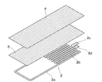
図2は図1に示す円筒体から成るコア本体1上に貼り付ける発熱層2、絶縁層3、熱伝導層4の分解斜視図、図3は発熱層の平面図を示している。発熱層2は例えば厚さ30μm程度のSUS(不銹鋼)から成る帯状箔導体を所定幅の帯状導体2aに打ち抜きにより加工し、部分的に密集させた密集部2bを有している。そして、端部2c、2d間に電流を流して帯状導体2aを発熱させることができる。
FIG. 2 is an exploded perspective view of the heat generating
密集部2bにおいては、細条の帯状導体2aを折り返して密に張り巡らすことにより、発熱量が大きくなるようにされている。密集部2bでは、帯状導体2aはコア本体1の長手方向に沿って平行部が多く、かつ平行部同士の隙間が小さくされており、コア本体1に貼り付ける場合に円周方向への屈曲が容易となる。
In the
発熱層2上には、発熱層2とほぼ同じ大きさを有するPET等の電気絶縁性の高い材料から成る絶縁層3、銅箔等の熱伝導率の良い材料から成る熱伝導層4が順次に積層されている。実際には、例えば絶縁層3上に貼り付けた金属箔層を打ち抜き、不要部分を剥離することにより発熱層2を得ることができ、絶縁層3はそのまま使用できる。
On the heat generating
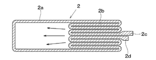
図4はコア本体1の表面に発熱層2を貼り付けた状態の斜視図を示しており、帯状導体2aの端部2c、2dに図示しない給電線を接続し、この発熱層2上に図示しない絶縁層3、熱伝導層4が積層されている。そして、発熱層2、絶縁層3、熱伝導層4を含めたコア本体1の内外面に、合成ゴムをモールドすることにより電熱ヒータ付グリップ部材が完成する。
FIG. 4 is a perspective view showing a state in which the heat generating
このように製作したグリップ部材は、オートバイ等のハンドルパイプに装着して使用され、給電線を介して発熱層2に電流を流すと、発熱層2が発熱し、使用者の手を暖めることができる。
The grip member manufactured in this way is used by being attached to a handle pipe of a motorcycle or the like, and when a current is passed through the heat generating
発熱層2に部分的に密集部2bを設けていることにより、この密集部2bの温度は急速に上昇し、最初に暖めるべき部分を局所的に暖めることができる。更に、絶縁層3を介して熱伝導率の高い熱伝導層4から成る熱拡散部を設けたことにより、密集部2bにおいて発生した熱を、熱拡散により矢印で示すように、帯状導体2aの配置が粗、或いは帯状導体2aがなく発熱量が少ない領域に拡散させることができ、グリップ全体においても良好な温度分布を得ることができる。
Since the heat generating
密集部2bは電力を効率良く熱に変換するために、グリップ部材の給電線と接続される側から半分の長さまで、更には1/3の間の個所に設置していればよい。また、周方向には特に限定されないが、全周から半周の範囲であればよく、密集部2bは指先が当たるような位置にあることが好ましい。
In order to efficiently convert electric power into heat, the
なお、発熱層2の密集部2b、或いは熱伝導層4の任意の個所に温度センサを取り付け、グリップの温度制御を行ってもよい。
Note that a temperature sensor may be attached to the
図5は実施例2におけるコア本体1の表面に発熱層2’を貼り付けた状態の斜視図を示している。
FIG. 5 is a perspective view showing a state in which the heat generating
本実施例2においては、コア本体1の所定の領域のみに発熱層2’の密集部2b’を貼り付け、この発熱層2’上に、絶縁層3’、熱伝導層4’が積層されている。なお、熱伝導層4’は発熱層2’を設けていないコア本体1の表面にも貼り付けられている。
In Example 2, the
これにより、例えば指先等が当接する領域を発熱層2’により優先的に暖めると共に、熱伝導層4’によりグリップ全体に熱を拡散することができる。
Thereby, for example, the region where the fingertip or the like abuts can be preferentially warmed by the heat generating
図6は実施例3における発熱層12の平面図を示している。なお、本実施例3においては、実施例1において用いた熱伝導層4を省略することができる。
FIG. 6 shows a plan view of the heat generating
本実施例3においては、実施例1と同様に帯状導体12aを部分的に密集させた密集部12bを設けていると共に、大きな面積の帯状箔導体から成る熱拡散部としての熱伝熱部12cを例えば2個所に有している。この熱伝熱部12cは電気抵抗が小さいため、熱伝熱部12cでは殆ど発熱はしないが、熱伝導率は高く熱を良好に伝熱できる。
In the third embodiment, as in the first embodiment, a
従って、端部12d、12eから給電線を介して電流を流すと、密集部12bにより発熱した熱は、帯状導体12aを介して熱伝熱部12cに拡散し、グリップ全体で良好な温度分布を得ることができる。
Therefore, when a current is passed from the
1 コア本体
2、2’、12 発熱層
2a、12a 帯状導体
2b、2b’、12b 密集部
3、3’ 絶縁層
4、4’ 熱伝導層
12c 熱伝熱部
DESCRIPTION OF
Claims (5)
Priority Applications (1)
| Application Number | Priority Date | Filing Date | Title |
|---|---|---|---|
| JP2007034441A JP2008195312A (en) | 2007-02-15 | 2007-02-15 | Grip member with electric heater |
Applications Claiming Priority (1)
| Application Number | Priority Date | Filing Date | Title |
|---|---|---|---|
| JP2007034441A JP2008195312A (en) | 2007-02-15 | 2007-02-15 | Grip member with electric heater |
Publications (2)
| Publication Number | Publication Date |
|---|---|
| JP2008195312A true JP2008195312A (en) | 2008-08-28 |
| JP2008195312A5 JP2008195312A5 (en) | 2010-12-16 |
Family
ID=39754651
Family Applications (1)
| Application Number | Title | Priority Date | Filing Date |
|---|---|---|---|
| JP2007034441A Pending JP2008195312A (en) | 2007-02-15 | 2007-02-15 | Grip member with electric heater |
Country Status (1)
| Country | Link |
|---|---|
| JP (1) | JP2008195312A (en) |
Cited By (2)
| Publication number | Priority date | Publication date | Assignee | Title |
|---|---|---|---|---|
| JP5898798B1 (en) * | 2015-03-27 | 2016-04-06 | 株式会社ファルテック | Handle grip and internal housing of handle grip |
| JP2016113002A (en) * | 2014-12-15 | 2016-06-23 | 株式会社日本ロック | Handle grip device |
Citations (6)
| Publication number | Priority date | Publication date | Assignee | Title |
|---|---|---|---|---|
| JPS59141688A (en) * | 1983-02-03 | 1984-08-14 | 成和機工株式会社 | Drilling rod disassembling method of drilling machine, drilling rod and wrench |
| JPS6194868A (en) * | 1984-10-15 | 1986-05-13 | Matsushita Electric Ind Co Ltd | Steering wheel for car |
| JPS61143965A (en) * | 1984-12-17 | 1986-07-01 | 田中貴金属工業株式会社 | Slide contact unit |
| JPH0210190A (en) * | 1988-06-29 | 1990-01-12 | Hitachi Ltd | Nuclear fusion device |
| JPH0254676A (en) * | 1988-08-19 | 1990-02-23 | Canon Inc | Picture processing method |
| JPH1081282A (en) * | 1996-09-11 | 1998-03-31 | Koito Mfg Co Ltd | Heater-built-in grip for vehicle |
-
2007
- 2007-02-15 JP JP2007034441A patent/JP2008195312A/en active Pending
Patent Citations (6)
| Publication number | Priority date | Publication date | Assignee | Title |
|---|---|---|---|---|
| JPS59141688A (en) * | 1983-02-03 | 1984-08-14 | 成和機工株式会社 | Drilling rod disassembling method of drilling machine, drilling rod and wrench |
| JPS6194868A (en) * | 1984-10-15 | 1986-05-13 | Matsushita Electric Ind Co Ltd | Steering wheel for car |
| JPS61143965A (en) * | 1984-12-17 | 1986-07-01 | 田中貴金属工業株式会社 | Slide contact unit |
| JPH0210190A (en) * | 1988-06-29 | 1990-01-12 | Hitachi Ltd | Nuclear fusion device |
| JPH0254676A (en) * | 1988-08-19 | 1990-02-23 | Canon Inc | Picture processing method |
| JPH1081282A (en) * | 1996-09-11 | 1998-03-31 | Koito Mfg Co Ltd | Heater-built-in grip for vehicle |
Cited By (5)
| Publication number | Priority date | Publication date | Assignee | Title |
|---|---|---|---|---|
| JP2016113002A (en) * | 2014-12-15 | 2016-06-23 | 株式会社日本ロック | Handle grip device |
| JP5898798B1 (en) * | 2015-03-27 | 2016-04-06 | 株式会社ファルテック | Handle grip and internal housing of handle grip |
| WO2016157888A1 (en) * | 2015-03-27 | 2016-10-06 | 株式会社ファルテック | Handle grip and inner housing for handle grip |
| JP2016185748A (en) * | 2015-03-27 | 2016-10-27 | 株式会社ファルテック | Handle grip and internal housing of the same |
| US10220904B2 (en) * | 2015-03-27 | 2019-03-05 | Faltec Co., Ltd. | Hand grip and inner housing of hand grip |
Similar Documents
| Publication | Publication Date | Title |
|---|---|---|
| JP5032835B2 (en) | Grip member with electric heater | |
| US8698043B2 (en) | Handle grip with heater | |
| JP4939025B2 (en) | Grip member for handle with electric heater | |
| JP2008195312A (en) | Grip member with electric heater | |
| KR101352232B1 (en) | Heated steering wheel | |
| JP7110764B2 (en) | heater device | |
| WO2007138957A1 (en) | Grip member provided with electrothermal heater | |
| CN207995425U (en) | Flat heater | |
| JP4685389B2 (en) | Grip member for handle with electric heater | |
| JP2008195312A5 (en) | ||
| KR102323142B1 (en) | Heating element and heater for air conditioner including the same | |
| JP4628768B2 (en) | Grip member with electric heater | |
| US20180146651A1 (en) | Heated Fishing Rod System | |
| JP2007035476A (en) | Planar heating element | |
| JP2008204263A (en) | Heating-type mouse | |
| JP4087513B2 (en) | Sheet heating element for electric toilet seat | |
| JP3131205U (en) | Grip heater | |
| JP5461220B2 (en) | Manufacturing method of planar heater and planar heater | |
| JP6723935B2 (en) | 3D type planar heater | |
| TWM346391U (en) | Heat-conducting toilet seat pad | |
| JP2016113002A (en) | Handle grip device | |
| TWM515865U (en) | Electric wax carver having electric carving head with wound coil | |
| JP2008023141A (en) | Warmed toilet seat | |
| CN208891090U (en) | A kind of heating tube and the heating device comprising it | |
| TWI594735B (en) | Electric wax wound coil electric wax knife |
Legal Events
| Date | Code | Title | Description |
|---|---|---|---|
| A621 | Written request for application examination |
Free format text: JAPANESE INTERMEDIATE CODE: A621 Effective date: 20091029 |
|
| A521 | Written amendment |
Free format text: JAPANESE INTERMEDIATE CODE: A523 Effective date: 20100312 |
|
| A521 | Written amendment |
Free format text: JAPANESE INTERMEDIATE CODE: A523 Effective date: 20101026 |
|
| A131 | Notification of reasons for refusal |
Free format text: JAPANESE INTERMEDIATE CODE: A131 Effective date: 20110614 |
|
| A977 | Report on retrieval |
Free format text: JAPANESE INTERMEDIATE CODE: A971007 Effective date: 20110616 |
|
| A02 | Decision of refusal |
Free format text: JAPANESE INTERMEDIATE CODE: A02 Effective date: 20111101 |