JP2008194854A - Image forming apparatus, image processing apparatus, and its controlling method - Google Patents
Image forming apparatus, image processing apparatus, and its controlling method Download PDFInfo
- Publication number
- JP2008194854A JP2008194854A JP2007029712A JP2007029712A JP2008194854A JP 2008194854 A JP2008194854 A JP 2008194854A JP 2007029712 A JP2007029712 A JP 2007029712A JP 2007029712 A JP2007029712 A JP 2007029712A JP 2008194854 A JP2008194854 A JP 2008194854A
- Authority
- JP
- Japan
- Prior art keywords
- recording
- image
- scan
- scanning
- image data
- Prior art date
- Legal status (The legal status is an assumption and is not a legal conclusion. Google has not performed a legal analysis and makes no representation as to the accuracy of the status listed.)
- Pending
Links
Images


Classifications
-
- G—PHYSICS
- G06—COMPUTING; CALCULATING OR COUNTING
- G06K—GRAPHICAL DATA READING; PRESENTATION OF DATA; RECORD CARRIERS; HANDLING RECORD CARRIERS
- G06K15/00—Arrangements for producing a permanent visual presentation of the output data, e.g. computer output printers
- G06K15/02—Arrangements for producing a permanent visual presentation of the output data, e.g. computer output printers using printers
- G06K15/10—Arrangements for producing a permanent visual presentation of the output data, e.g. computer output printers using printers by matrix printers
- G06K15/102—Arrangements for producing a permanent visual presentation of the output data, e.g. computer output printers using printers by matrix printers using ink jet print heads
- G06K15/105—Multipass or interlaced printing
- G06K15/107—Mask selection
-
- B—PERFORMING OPERATIONS; TRANSPORTING
- B41—PRINTING; LINING MACHINES; TYPEWRITERS; STAMPS
- B41J—TYPEWRITERS; SELECTIVE PRINTING MECHANISMS, i.e. MECHANISMS PRINTING OTHERWISE THAN FROM A FORME; CORRECTION OF TYPOGRAPHICAL ERRORS
- B41J2/00—Typewriters or selective printing mechanisms characterised by the printing or marking process for which they are designed
- B41J2/005—Typewriters or selective printing mechanisms characterised by the printing or marking process for which they are designed characterised by bringing liquid or particles selectively into contact with a printing material
- B41J2/01—Ink jet
- B41J2/21—Ink jet for multi-colour printing
- B41J2/2121—Ink jet for multi-colour printing characterised by dot size, e.g. combinations of printed dots of different diameter
- B41J2/2128—Ink jet for multi-colour printing characterised by dot size, e.g. combinations of printed dots of different diameter by means of energy modulation
-
- H—ELECTRICITY
- H04—ELECTRIC COMMUNICATION TECHNIQUE
- H04N—PICTORIAL COMMUNICATION, e.g. TELEVISION
- H04N1/00—Scanning, transmission or reproduction of documents or the like, e.g. facsimile transmission; Details thereof
- H04N1/40—Picture signal circuits
- H04N1/405—Halftoning, i.e. converting the picture signal of a continuous-tone original into a corresponding signal showing only two levels
Landscapes
- Engineering & Computer Science (AREA)
- Physics & Mathematics (AREA)
- Mathematical Physics (AREA)
- General Engineering & Computer Science (AREA)
- General Physics & Mathematics (AREA)
- Theoretical Computer Science (AREA)
- Multimedia (AREA)
- Signal Processing (AREA)
- Ink Jet (AREA)
Abstract
Description
本発明は画像形成装置、画像処理装置およびその制御方法に関し、特に、入力画像よりも低階調による画像形成を行う画像形成装置、画像処理装置およびその制御方法に関する。 The present invention relates to an image forming apparatus, an image processing apparatus, and a control method thereof, and more particularly to an image forming apparatus, an image processing apparatus, and a control method thereof that perform image formation with a lower gradation than an input image.
ワードプロセッサやパーソナルコンピュータ、ファクシミリ等の画像出力装置としては一般に、所望される文字や画像等の情報を、用紙やフィルム等のシート状の記録媒体に記録する記録装置が用いられる。このような記録装置としては様々な記録方式のものがあるが、なかでも記録媒体に記録剤を付着させることで記録媒体上に画像を形成する方式が広く実用化されており、このような方式の代表例として、インクジェット記録方式が知られている。 As an image output device such as a word processor, personal computer, or facsimile, a recording device that records information such as desired characters and images on a sheet-like recording medium such as paper or film is generally used. As such a recording apparatus, there are various recording methods, and among them, a method of forming an image on a recording medium by attaching a recording agent to the recording medium has been widely put into practical use. As a representative example, an ink jet recording method is known.
インクジェット記録方式を適用した記録装置においては、記録速度の向上や高画質化等を実現するために、同一色同一濃度のインクを吐出可能なインク吐出口(ノズル)の複数を集積配列したノズル群を備える。さらに、画質の向上を実現するために、同一色で濃度の異なるインクを吐出可能としたノズル群や、同一色で同一濃度のインクの吐出量を何段階かに変えて吐出可能としたノズル群が設けられる場合もある。 In a recording apparatus to which an ink jet recording method is applied, a nozzle group in which a plurality of ink discharge ports (nozzles) capable of discharging ink of the same color and the same density are arranged in an integrated manner in order to improve recording speed and improve image quality. Is provided. Furthermore, in order to improve image quality, a nozzle group that can eject ink of the same color and different density, or a nozzle group that can eject by changing the ejection amount of ink of the same color and the same density in several stages May be provided.
このような記録装置において、記録される画像の品位は記録ヘッド単体の性能に依存する部分が大きい。例えば、記録ヘッドの吐出口の形状や、吐出ヒータやピエゾ素子などのバラツキ等、記録ヘッドの製作工程において生じる僅かな誤差が、吐出されるインクの吐出量や方向に大きく影響を及ぼす。すなわち、このような僅かな誤差が、形成される画像に濃度ムラが発生して画質が劣化してしまう原因となる。 In such a recording apparatus, the quality of the recorded image largely depends on the performance of the recording head alone. For example, slight errors that occur in the manufacturing process of the recording head, such as the shape of the discharge port of the recording head and variations in the discharge heater and piezo element, greatly affect the discharge amount and direction of the discharged ink. That is, such a slight error causes density unevenness in the formed image and causes image quality to deteriorate.
そこでこのような濃度ムラ発生を抑制するための対策として、マルチパス記録方式が知られている(例えば、特許文献1参照)。かかる技術によれば、画像処理と印字制御を組み合わせることで、白スジや濃度ムラなどによる画質の低下を抑えつつ、画像の高速形成を可能としている。 Therefore, a multi-pass printing method is known as a countermeasure for suppressing such density unevenness (see, for example, Patent Document 1). According to such a technique, by combining image processing and print control, it is possible to form an image at high speed while suppressing deterioration in image quality due to white stripes and density unevenness.
以下、図51を用いてマルチパス記録方式について詳細に説明する。 Hereinafter, the multi-pass recording method will be described in detail with reference to FIG.
図51において、5101はマルチヘッドであり、ここでは説明を簡略化するために8個のノズル5102によって構成されているものとする。5103は、マルチノズル5102によって吐出されたインクドロップレットである。通常、所定の記録媒体における同一の主走査記録領域を1回の走査(スキャン)で完成させる場合は、図51に示すように揃った吐出量で、揃った方向にインクが吐出されることが理想である。
In FIG. 51,
しかし、実際にはノズル1つ1つにバラツキがあり、1回の走査で印字を行った場合には、それぞれのノズルにより吐出されるインクドロップの大きさや向きにバラツキが生じる。これにより、ヘッド主走査方向に対して、周期的に白地の部分が存在したり、また逆に必要以上にドットが重なりあったりする。このような状態で着弾されたドットの集まりは、ノズルの配列方向に対して濃度ムラとして感知される。 However, there is actually a variation in each nozzle, and when printing is performed by one scan, there is a variation in the size and direction of the ink drop ejected by each nozzle. As a result, white portions periodically exist in the head main scanning direction, and conversely, dots overlap more than necessary. A collection of dots landed in such a state is perceived as density unevenness in the nozzle arrangement direction.
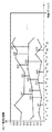
そこで、マルチパス記録方式では図52に示すように、マルチヘッド5202によって複数回(この例では3回)の主走査を行う。図中、縦方向8画素の半分である4画素を単位とする記録走査領域は、2回の記録走査(パス)で完成している。この場合、マルチヘッド5201内の8ノズルは、上側の4ノズル(上側ノズル群)と下側の4ノズル(下側ノズル群)のグループに分けられる。1ノズルが1回のスキャンで記録するドットは、画像データをある所定の画像データ配列に従って、約半分に間引いたものである。そして、2回目のスキャン時に残りの約半分のドットを、先に形成した画像に埋め込むことによって、4画素単位領域の記録を完成させる。 Therefore, in the multi-pass recording method, as shown in FIG. 52, the multi-head 5202 performs main scanning a plurality of times (in this example, three times). In the figure, the recording scan area in units of 4 pixels, which is half of the 8 pixels in the vertical direction, is completed by two recording scans (passes). In this case, the 8 nozzles in the multi-head 5201 are divided into groups of 4 upper nozzles (upper nozzle group) and 4 lower nozzles (lower nozzle group). The dots recorded by one nozzle in one scan are obtained by thinning image data by about half according to a predetermined image data array. Then, the remaining half of the dots are embedded in the previously formed image during the second scan, thereby completing the recording of the 4-pixel unit area.
マルチパス記録方式においてはまた、所定の配列に従って1スキャン目と2スキャン目で互いの埋め合わせを行う。このために使用される画像データ配列(間引きマスクパターン)としては通常、図53に示すように、縦横1画素毎に千鳥格子状をなす配列が用いられる。従って、単位印字領域(ここでは4画素単位)においては、千鳥格子を印字する1スキャン目と、逆千鳥格子を印字する2スキャン目によって印字が完成される。図53の上段、中段、下段の図はそれぞれ、上述した千鳥パターン、逆千鳥パターンを用いて同一領域における記録が完成されていく様子を示している。すなわち、記録媒体上の所定領域に対し、まず図53上段に示すように、1スキャン目では、下4ノズルを用いて千鳥パターン(黒丸印)の記録を行う。次に図53中段に示すように、該領域に対する2スキャン目には、紙送りを4画素分だけ行い、全8ノズルを用いて逆千鳥パターン(白丸印)の記録を行う。さらに図53の下段に示すように、該領域に対する3スキャン目では再度、4画素分の紙送りを行い、上4ノズルを用いて千鳥パターンを記録する。 In the multi-pass printing method, the first scan and the second scan are compensated for each other according to a predetermined arrangement. As an image data array (thinning-out mask pattern) used for this purpose, an array having a staggered pattern for each vertical and horizontal pixel is usually used as shown in FIG. Therefore, in the unit printing area (in this case, in units of four pixels), printing is completed by the first scan for printing the staggered lattice and the second scan for printing the inverted staggered lattice. The upper, middle, and lower diagrams in FIG. 53 show how recording in the same area is completed using the above-described zigzag pattern and inverted zigzag pattern, respectively. That is, first, as shown in the upper part of FIG. 53, a staggered pattern (black circles) is recorded in the first scan using the lower four nozzles in a predetermined area on the recording medium. Next, as shown in the middle part of FIG. 53, in the second scan with respect to the area, paper feeding is performed for 4 pixels, and a reverse zigzag pattern (white circles) is recorded using all 8 nozzles. Further, as shown in the lower part of FIG. 53, in the third scan with respect to the area, paper feeding for 4 pixels is performed again, and a staggered pattern is recorded using the upper 4 nozzles.
このマルチパス記録方式を実施すれば、図52で示したようなバラツキを有するマルチヘッドを使用した場合でも、該バラツキによる記録領域への影響が半減されるので、形成される画像において濃度ムラが緩和される。 If this multi-pass recording method is used, even when a multi-head having a variation as shown in FIG. 52 is used, the influence on the recording area due to the variation is halved. Alleviated.
しかしながら、このようなマルチパス記録を行った際にも、各記録走査の記録率によっては濃度ムラが解消されにくい場合がある。そこでマルチパス記録を行う際に、各記録走査間の副走査方向送り量(紙送り量)を乱数的に変化させることにより、各領域のピッチを可変として、濃度ムラを低減する技術が提案されている(例えば、特許文献2参照)。 However, even when such multi-pass printing is performed, density unevenness may be difficult to eliminate depending on the printing rate of each printing scan. Therefore, a technique has been proposed for reducing density unevenness by changing the sub-scanning direction feed amount (paper feed amount) between print scans in a random manner so that the pitch of each region is variable when performing multi-pass printing. (For example, refer to Patent Document 2).
また、マルチパス記録方式において、1回の記録走査に使用する記録ヘッドのノズル数を変更することで、記録媒体の搬送方向上の先端および後端領域での画質劣化を低減する方法も提案されている(例えば、特許文献3参照)。該技術によれば、記録媒体の搬送方向上の先端および後端領域では、記録媒体搬送の位置精度が低下するため、そのような領域に対しては搬送量および使用ノズル数を減らすことにより、位置精度低下に起因する記録画像品位の劣化を目立たなくしている。
上述した紙送り量を乱数的に変化させるマルチパス記録方式では、副走査方向に周期的に発生する濃度ムラを低減することが可能である。しかしながら該方式によれば、各主走査においてマスクパターンを用いて画像を形成するため、紙送りずれが発生した場合には画像の粒状性が悪化し出力画像の画質品位が低下してしまう。 In the multipass printing method in which the paper feed amount is changed randomly, it is possible to reduce density unevenness that occurs periodically in the sub-scanning direction. However, according to this method, an image is formed using a mask pattern in each main scan, and therefore, when paper feed misalignment occurs, the granularity of the image deteriorates and the image quality of the output image decreases.
以下、この紙送りずれによって粒状性が悪化する様子を、図54、図55を用いて説明する。図54、図55は、図53のような千鳥マスクパターンを用いて2パス印字を行う例を示す図であり、図54は記録媒体の紙送りのずれが生じない場合の記録例を、図55は紙送りずれが生じた場合の記録例を示す。 Hereinafter, how the graininess deteriorates due to this paper feed deviation will be described with reference to FIGS. 54 and 55. FIG. 54 and 55 are diagrams showing an example of performing two-pass printing using the staggered mask pattern as shown in FIG. 53, and FIG. 54 is a diagram showing a recording example in the case where the paper feed of the recording medium does not shift. Reference numeral 55 denotes an example of recording when a paper feed deviation occurs.
図54に示すように、紙送りずれがない場合には、入力の2値ハーフトーン画像で指定された位置に正確にドットが打たれる。なお、ここではノズル吐出バラツキは発生していないものとする。しかしながら図55に示すように、2パス目の印字前に記録媒体の紙送りが矢印方向ずれた場合には、記録媒体上に形成された画像は粒状性が悪化してしまう。これは、マスクパターンによるマルチパス記録方式では、最終的に出力される画像の分散性が高い場合でも、図55に示すように、各パスで打たれるドットの分散性が低いためである。 As shown in FIG. 54, when there is no paper feed misalignment, dots are accurately printed at positions designated by the input binary halftone image. Here, it is assumed that there is no nozzle discharge variation. However, as shown in FIG. 55, when the paper feed of the recording medium is shifted in the direction of the arrow before the second pass printing, the image formed on the recording medium is deteriorated in graininess. This is because in the multi-pass printing method using the mask pattern, even when the finally output image has high dispersibility, as shown in FIG.
また、紙送りのずれ量は紙搬送時毎に異なることにより、以下のような問題が生じる。例えば、入力データ値が同じ領域でも、紙送りずれが発生していない図54の状態と、紙送りずれが発生する図55の状態が隣接することで、ノズルのバラつきから生じる濃度のムラよりも長周期の濃度のムラが発生する。 Further, the following problem arises because the amount of deviation of the paper feed differs every time the paper is conveyed. For example, even in a region where the input data value is the same, the state shown in FIG. 54 where no paper feed deviation occurs and the state shown in FIG. 55 where paper feed deviation occurs are adjacent to each other. Long-period density unevenness occurs.
一方、上述した1回の記録走査に使用する記録ヘッドのノズル数を変更して、記録媒体の搬送方向上の先端および後端領域での画質劣化を低減する方法では、以下のような問題があった。すなわち、紙送り量の最小単位(例えば所定のノズル数分)の整数倍でしか、紙送り量を設定することができないため、制限されたノズルを効率的に使用できなくなることがある。 On the other hand, the above-described method for changing the number of nozzles of the recording head used for one recording scan to reduce image quality degradation in the leading and trailing end regions in the recording medium conveyance direction has the following problems. there were. That is, since the paper feed amount can be set only by an integral multiple of the minimum unit of the paper feed amount (for example, a predetermined number of nozzles), the limited nozzles may not be used efficiently.
本発明は上述した問題を解決するためになされたものであり、以下の機能を有する画像形成装置、画像処理装置およびその制御方法を提供することを目的とする。すなわち、マルチパス印字において、記録素子のバラツキによる濃度ムラや記録媒体の搬送量のずれによる粒状性悪化および長周期の濃度ムラを低減し、高画質化を実現する。 SUMMARY An advantage of some aspects of the invention is that it provides an image forming apparatus, an image processing apparatus, and a control method thereof having the following functions. That is, in multi-pass printing, it is possible to reduce the density unevenness due to the variation of the recording elements and the graininess deterioration due to the shift of the recording medium conveyance amount and the long-period density unevenness, thereby realizing high image quality.
上記目的を達成するための一手段として、本発明の画像形成装置は以下の構成を備える。 As a means for achieving the above object, an image forming apparatus of the present invention comprises the following arrangement.
すなわち、複数の記録素子を備えた記録ヘッドを複数の領域に分割し、記録媒体上の同一領域に対して該分割された領域単位での走査によって画像を形成する画像形成装置であって、画像データを入力する画像入力手段と、前記記録ヘッドの主走査ごとに、前記記録素子ごとの記録量分割率を設定したテーブルを保持するテーブル保持手段と、前記画像データに応じて、前記記録ヘッドの主走査ごとに、前記記録素子ごとの記録量を、前記テーブルに基づいて設定する走査内記録量設定手段と、前記走査内記録量設定手段で設定された記録量に対し、N値化処理(Nは2以上の整数)を施して形成対象となるドットパターンを作成するN値化手段と、を有し、前記テーブルは、前記記録媒体上の同一領域を形成するための主走査の回数と、主走査ごとに使用する記録素子数に基づいて作成されていることを特徴とする。 That is, an image forming apparatus that divides a recording head including a plurality of recording elements into a plurality of areas and forms an image by scanning the same area on the recording medium in units of the divided areas. Image input means for inputting data, table holding means for holding a table in which the recording amount division ratio for each recording element is set for each main scan of the recording head, and according to the image data, An intra-scan recording amount setting unit that sets a recording amount for each recording element for each main scanning based on the table, and an N-value conversion process for the recording amount set by the intra-scan recording amount setting unit ( N is a N-value conversion unit that creates a dot pattern to be formed by applying N to an integer of 2 or more, and the table includes the number of main scans for forming the same area on the recording medium. , main Characterized in that it is created based on the number of recording elements to be used for each 査.
本発明によれば、マルチパス印字において、同一記録領域の主走査回数と、主走査ごとに使用する記録素子数を任意に設定することにより、以下の機能を有する画像形成装置、画像処理装置およびその制御方法を提供することができる。すなわち、記録素子のバラツキによる濃度ムラや記録媒体の搬送量のずれによる粒状性悪化および長周期の濃度ムラを低減し、高画質化が実現される。 According to the present invention, in multi-pass printing, by arbitrarily setting the number of main scans in the same recording area and the number of recording elements used for each main scan, an image forming apparatus, an image processing apparatus, and The control method can be provided. In other words, density unevenness due to variations in recording elements, graininess deterioration due to deviations in the conveyance amount of the recording medium, and long-period density unevenness are reduced, and high image quality is achieved.
以下、添付の図面を参照して、本発明をその好適な実施形態に基づいて詳細に説明する。なお、以下の実施形態において示す構成は一例に過ぎず、本発明は図示された構成に限定されるものではない。 Hereinafter, the present invention will be described in detail based on preferred embodiments with reference to the accompanying drawings. The configurations shown in the following embodiments are merely examples, and the present invention is not limited to the illustrated configurations.
<第1実施形態>
図1は、本実施形態による画像形成システムの構成を示したブロック図である。図1において、1は画像処理装置、2はプリンタを示す。なお、画像処理装置1は例えば一般的なパーソナルコンピュータにインストールされたプリンタドライバによって実施され得る。その場合、以下に説明する画像処理装置1の各部は、コンピュータが所定のプログラムを実行することにより実現されることになる。また、別の構成としては、例えば、プリンタ2が画像処理装置1を含む構成としてもよい。
<First Embodiment>
FIG. 1 is a block diagram showing the configuration of the image forming system according to the present embodiment. In FIG. 1, 1 is an image processing apparatus, and 2 is a printer. The
画像処理装置1とプリンタ2は、プリンタインタフェースやネットワークインタフェースによって接続されている。画像処理装置1は、画像データ入力端子101より印刷対象の画像データを入力し、これを入力画像バッファ102に格納する。色分解処理部103は、入力された画像データをプリンタ2が備えるインク色へ色分解する。この色分解処理に際しては、色分解用ルックアップテーブル(LUT)104が参照される。記録データ設定部105は、記録データ設定用LUT106に基づき、色分解処理部103にて分解された各インク色値から各走査ごとの記録データを設定し、記録データ格納メモリ107に格納する。なお、本実施形態における記録データとは、各走査における各インク色の記録インク量である。
The
ハーフトーン処理部108は、記録データ格納メモリ107に格納された多階調(3階調以上)の画像データを2値に変換し、ハーフトーン画像格納メモリ109に格納する。以上一連の処理によって形成された2値画像データは、出力端子110を介してプリンタ2へ出力される。
The
プリンタ2においては、記録ヘッド201を記録媒体202に対して相対的に縦横に移動することにより、画像処理装置1にて形成された2値画像データを記録媒体上に形成する。記録ヘッド201としては電子写真方式、熱転写方式、インクジェット方式等のものを用いることができ、いずれも一つ以上の記録素子(インクジェット方式であればノズル)を有する。移動部203は、ヘッド制御部204の制御下で、記録ヘッド201を移動する。搬送部205は、ヘッド制御部204の制御下で、記録媒体を搬送する。また、インク色及び吐出量選択部206は、画像処理装置1により形成された各色の2値画像データに基づいて、記録ヘッド201に搭載されるインク色の中から、インク色と、吐出可能なインク吐出量を選択する。
In the
図2は、記録ヘッド201の構成例を示す図である。本実施形態ではシアン(C)、マゼンタ(M)、イエロー(Y)、ブラック(K)の4色のインクに加え、相対的にインク濃度が低い淡シアン(Lc)、淡マゼンタ(Lm)を含めた6色のインクを、記録ヘッド201に搭載している。
FIG. 2 is a diagram illustrating a configuration example of the
なお、図2においては、説明を簡単にするため用紙搬送方向にノズルが一列に配置された構成を示しているが、ノズルの数、配置はこの例に限られるものではない。例えば、同一色でも吐出量が異なるノズル列を有しても良いし、同一吐出量ノズルが複数列あっても良いし、ノズルがジグザグに配置されているような構成であっても良い。また、図2ではインク色の配置順序はヘッド移動方向に一列となっているが、用紙搬送方向に一列に配置する構成であっても良い。 2 shows a configuration in which nozzles are arranged in a line in the paper conveyance direction for the sake of simplicity, the number and arrangement of nozzles are not limited to this example. For example, there may be nozzle rows with the same color but different discharge amounts, there may be a plurality of nozzles with the same discharge amount, or the nozzles may be arranged in a zigzag manner. In FIG. 2, the ink color is arranged in a line in the head movement direction, but may be arranged in a line in the paper transport direction.
次に、上述した機能構成を備えた本実施形態の画像処理装置1における処理について、図3のフローチャートを用いて説明する。
Next, processing in the
まず、多階調のカラー入力画像データが入力端子101より入力され、入力画像バッファ102に格納される(S101)。ここで入力画像データは、レッド(R)、グリーン(G)、ブルー(B)の3つの色成分によりカラー画像データを構築している。
First, multi-tone color input image data is input from the
次に、色分解処理部103にて、入力画像バッファ102に格納された多階調のカラー入力画像データに対し、色分解用LUT104を用いて、RGBからCMYK及びLcLmのインク色プレーンへの色分解処理を行う(S102)。本実施形態では、色分解処理後の各画素データを8ビットとして扱うが、それ以上の階調数への変換を行っても構わない。
Next, the color
上述したように本実施形態における記録ヘッド201は、6種類の各インク色を保有する。そのため、RGBのカラー入力画像データは、CMYKLcLm各プレーンの計6プレーンの画像データへ変換される。即ち、6種類のインク色に対応した6種類のプレーンの画像データが生成される。
As described above, the
以下、本実施形態における色分解処理の詳細について、図4を用いて説明する。 Hereinafter, the details of the color separation processing in the present embodiment will be described with reference to FIG.
図4は、色分解処理部103における入出力データの詳細を示している。同図に示すように入力された画像データR'G'B'は、色分解用LUT104を参照して次式の通りに、CMYKLcLmデータへ変換される。
FIG. 4 shows details of input / output data in the color
C=C_LUT_3D(R',G',B') ・・・(1)
K=M_LUT_3D(R',G',B') ・・・(2)
Y=Y_LUT_3D(R',G',B') ・・・(3)
K=K_LUT_3D(R',G',B') ・・・(4)
Lc=Lc_LUT_3D(R',G',B') ・・・(5)
Lm=Lm_LUT_3D(R',G',B') ・・・(6)
ここで、式(1)〜(6)の右辺に定義される各関数が、色分解用LUT104の内容に該当する。色分解用LUT104はレッド、グリーン、ブルーの3入力値から、各インク色への出力値を定める。本実施形態では、CMYKLcLmの6色を具備する構成であるため、3入力値から6出力値を得るLUT構成となる。
C = C_LUT — 3D (R ′, G ′, B ′) (1)
K = M_LUT — 3D (R ′, G ′, B ′) (2)
Y = Y_LUT — 3D (R ′, G ′, B ′) (3)
K = K_LUT — 3D (R ′, G ′, B ′) (4)
Lc = Lc_LUT — 3D (R ′, G ′, B ′) (5)
Lm = Lm_LUT — 3D (R ′, G ′, B ′) (6)
Here, each function defined on the right side of the equations (1) to (6) corresponds to the contents of the
以上の処理により、本実施形態における色分解処理が完了する。 With the above processing, the color separation processing in this embodiment is completed.
図3に戻り、次に、記録データ設定部105は、走査番号k及び色分解データ切り出し位置としてのY座標を示すYcut(k)を設定する(S103)。Ycut(k)はすなわち、走査番号kにおける色分解データ切り出し位置であり、ノズル上端座標に相当する。なお、走査番号kの初期値は1であり、処理ループ毎に1づつインクリメントされる。
Returning to FIG. 3, next, the recording
ここで、8個のノズル列を具備し、画像上の同一主走査記録領域に対して4回のスキャンで画像を形成させる4パス印字の場合を例として、色分解データ切り出し位置Y座標Ycutの設定法を、図5および図6を用いて説明する。 Here, as an example of four-pass printing having eight nozzle rows and forming an image by four scans for the same main scanning recording area on the image, the color separation data cut-out position Y coordinate Ycut The setting method will be described with reference to FIGS.
図5は、走査番号kにおける走査後の紙送り量LF(k)(なお、実際の搬送量はノズル間ピッチとLF(k)で決まる値とする)が一定である場合を示す図である。同図に示すように、一般的な4パス印字では走査番号k=1において、ノズル501の下端1/4(ノズル番号n7,n8)のみを使用して画像形成を行う。続いて走査番号k=2では、走査番号k=1に対して、ノズル長の1/4分の紙送り(紙送り量LF(1)=2(ノズル数))を行い、ノズル501の下端1/2(ノズル番号n5、n6、n7、n8)を使用して画像形成を行う。さらに走査番号k=3では、走査番号k=2に対して、ノズル長の1/4分の紙送り(LF(2)=2)を行い、ノズル501の下端3/4(ノズル番号n3、n4、n5、n6、n7、n8)を使用して画像形成を行う。
FIG. 5 is a diagram showing a case where the paper feed amount LF (k) after scanning at the scan number k (the actual carry amount is a value determined by the nozzle pitch and LF (k)) is constant. . As shown in the figure, in general four-pass printing, image formation is performed using only the lower end quarter (nozzle numbers n7 and n8) of the
以上のような処理を繰り返すことにより、最終出力画像502が形成される。図5の例によれば、走査番号k=1における色分解データ切り出し位置Ycut(1)=−6となることが分かる。
By repeating the above processing, a
ここで、紙送り量LF(k)が一定である場合の、色分解データ切り出し位置Ycut(k)を一般化すると、ノズル列数:Nzzl、パス数:Pass、走査番号:k、として次式で与えられる。 Here, when the color separation data cutout position Ycut (k) is generalized when the paper feed amount LF (k) is constant, the following equation is obtained as the number of nozzle rows: Nzzl, the number of passes: Pass, and the scanning number: k. Given in.
Ycut(k)=−Nzzl+(Nzzl/Pass)×k ・・・(7)
次に、走査番号kにおける走査後の紙送り量LF(k)を変化させる場合について、図6を用いて説明する。同図に示すように、まず走査番号k=1において、ノズル601の最下端ノズルn8のみを使用して画像形成を行う。このとき、走査番号k=1における色分解データ切り出し位置は、Ycut(1)=−7となる。続いて走査番号k=2では、走査番号k=1に対して、ノズル長の3/8分の紙送り(LF(1)=3)を行い、ノズルn5、n6、n7、n8を使用して画像形成を行う。よって走査番号k=2における色分解データ切り出し位置は、Ycut(2)=−4となる。さらに走査番号k=3では、走査番号k=2に対して、ノズル長の1/8分の紙送り(LF(2)=1)を行い、ノズルn4、n5、n6、n7、n8を使用して画像形成を行う。
Ycut (k) = − Nzzl + (Nzzl / Pass) × k (7)
Next, the case where the paper feed amount LF (k) after scanning at the scanning number k is changed will be described with reference to FIG. As shown in the figure, first, at the scan number k = 1, image formation is performed using only the lowest nozzle n8 of the
以上のような処理を繰り返すことにより、最終出力画像602が形成される。
By repeating the above processing, a
以上説明したように、本実施形態の特徴の一つである、走査後の紙送り量LF(k)が一定でない場合において、色分解データ切り出し位置Ycutは次式で与えられる。 As described above, when the paper feed amount LF (k) after scanning, which is one of the features of this embodiment, is not constant, the color separation data cutout position Ycut is given by the following equation.
k=1のとき、
Ycut(k)=−Nzzl+(k=1における使用ノズル数) ・・・(8)
k≧1のとき、
Ycut(k)=Ycut(k−1)+LF(k−1) ・・・(9)
なお、走査番号kにおける色分解データ切り出し位置Ycut(k)は、記録データ設定用LUT106に記録されているが、その詳細については後述する。
When k = 1
Ycut (k) = − Nzzl + (number of nozzles used at k = 1) (8)
When k ≧ 1,
Ycut (k) = Ycut (k−1) + LF (k−1) (9)
The color separation data cut-out position Ycut (k) at the scan number k is recorded in the recording
以上のようにYcut(k)が設定されると、次に記録データ設定部105は、記録データ設定用LUT106と色分解後の画像データに基づき、走査毎の記録データ値を設定する(S104)。
When Ycut (k) is set as described above, the recording
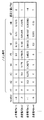
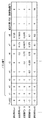
ここで図7に、8個のノズル列が一列に配置された構成を有する記録ヘッドを用いて、画像上の同一主走査記録領域に対して4回の走査で画像を形成する4パス印字を行う場合に、記録データ設定用LUT106に格納されるデータ例を示す。
Here, FIG. 7 shows a four-pass printing in which an image is formed by four scans for the same main scanning recording area on an image using a recording head having a configuration in which eight nozzle rows are arranged in one row. An example of data stored in the recording
記録データ設定用LUT106には図7に示すように、走査番号kごとに、色分解データ切り出し位置Ycut(k)、各ノズルに対する入力データの分割率、走査後の紙送り量LF(k)、が与えられている。
In the recording
ここで、各ノズルに対する入力データの分割率は、例えば図8に示すように設定される。図8において縦軸がノズル位置、横軸が分割率であり、入力DUTYを1とした場合に、各分割率は0〜1の実数値として設定される。本実施形態において、各ノズルに対する分割率は、印字パス数、紙送り量、使用ノズル数によって決定される。本実施形態における分割率の設定は、予め作成された入力DUTY分割テーブルに基づいて行われるが、このテーブルの作成方法についての詳細は後述する。また、本実施形態において、入力DUTYとは色分解処理後の各インク値を示す。 Here, the division ratio of the input data for each nozzle is set, for example, as shown in FIG. In FIG. 8, when the vertical axis is the nozzle position, the horizontal axis is the division ratio, and the input DUTY is 1, each division ratio is set as a real value from 0 to 1. In this embodiment, the division ratio for each nozzle is determined by the number of print passes, the paper feed amount, and the number of used nozzles. The setting of the division ratio in the present embodiment is performed based on an input DUTY division table created in advance. Details of the method of creating this table will be described later. In this embodiment, the input DUTY indicates each ink value after color separation processing.
ステップS104で設定される記録データは、図9に示すように、記録データ設定用LUT106と色分解データの積として設定される。すなわち、図9の左項に示されるように、色分解後のデータに対して、ノズルごとに設定されたDUTY分割率(記録データの分割率)を乗じることにより、その結果が図9の右項に示されるように、ノズルごとの記録データとして設定される。これにより、実際の走査時には、ターゲットとする色分解データに対し、各ノズルは記録データ分のみのインクを吐出して画像を形成する。
The recording data set in step S104 is set as the product of the recording
ここで本実施形態においては、対応するノズルが画像Yアドレスの領域外座標になるときは、記録データを0とする。例えば、走査番号k=1では、図10に示すように、ノズル列上端3/4で画像Yアドレスが負になるため記録データ値=0が代入され、ノズル列下端1/4には有意な値が代入される。
Here, in the present embodiment, when the corresponding nozzle is outside the area of the image Y address, the recording data is set to 0. For example, when the scan number is k = 1, as shown in FIG. 10, since the image Y address becomes negative at the nozzle row
また、色分解データ切り出し位置Ycut(k)は走査番号kによって決まるため、走査番号k=1〜7の場合、記録データは図11に示すように決定される。図11においては、各走査番号ごとのノズル位置に対する記録データが示されており、走査番号ごとに記録データが異なっていることが分かる。図11における各記録データは、色分解データと、記録データ設定用LUT106の積により定まるため、紙送りしながらLUTとの積をとると、領域1の部分では、走査番号k=1〜4の4回の走査で形成される1ラスタの合計値が色分解データと同じになる。同様に領域2、3、4においても、1ラスタの合計値が色分解データと同じになる。
Further, since the color separation data cut-out position Ycut (k) is determined by the scan number k, when the scan number k = 1 to 7, the print data is determined as shown in FIG. In FIG. 11, the print data for the nozzle positions for each scan number is shown, and it can be seen that the print data differs for each scan number. Each print data in FIG. 11 is determined by the product of the color separation data and the print
上述したような記録データ設定部105における記録データの設定は、下式のように与えられる。なお、C'_(X,Y)、Lc'_(X,Y)、M'_(X,Y)、Lm'_(X,Y)、Y'_(X,Y)、K'_(X,Y)は、アドレス(X,Y)における各色の色分解データを示す。またC_d(X,Y)、Lc_d(X,Y)、M_d(X,Y)、Lm_d(X,Y)、Y_d(X,Y)、K_d(X,Y)は、アドレス(X,Y)における記録データを示す。またS_LUT(Y)は、アドレスYにおける記録データ設定用LUT106の値を示す。また、0≦nx<画像Xサイズ、0≦ny<Nzzl(ノズル列数:この場合8)、である。
The recording data setting in the recording
C_d(nx,ny)=C'_(nx,Ycut(k)+ny)×S_LUT(ny) ・・・(10)
Lc_d(nx,ny)=Lc'_(nx,Ycut(k)+ny)×S_LUT(ny)・・・(11)
M_d(nx,ny)=M'_(nx,Ycut(k)+ny)×S_LUT(ny) ・・・(12)
Lm_d(nx,ny)=Lm'_(nx,Ycut(k)+ny)×S_LUT(ny)・・・(13)
Y_d(nx,ny)=Y'_(nx,Ycut(k)+ny)×S_LUT(ny) ・・・(14)
K_d(nx,ny)=K'_(nx,Ycut(k)+ny)×S_LUT(ny) ・・・(15)
以上のように記録データ設定部105で設定された記録データは、記録データ格納メモリ107に格納される(S105)。すなわち、記録データ格納メモリ107は図12に示すように、縦方向がノズル数、横方向が画像のXサイズに相当するバンド状の記録データ値を、各色毎に格納する。
C_d (nx, ny) = C ′ _ (nx, Ycut (k) + ny) × S_LUT (ny) (10)
Lc_d (nx, ny) = Lc ′ _ (nx, Ycut (k) + ny) × S_LUT (ny) (11)
M_d (nx, ny) = M ′ _ (nx, Ycut (k) + ny) × S_LUT (ny) (12)
Lm_d (nx, ny) = Lm ′ _ (nx, Ycut (k) + ny) × S_LUT (ny) (13)
Y_d (nx, ny) = Y ′ _ (nx, Ycut (k) + ny) × S_LUT (ny) (14)
K_d (nx, ny) = K ′ _ (nx, Ycut (k) + ny) × S_LUT (ny) (15)
The recording data set by the recording
以下、上述した入力DUTY分割テーブルの作成方法について詳細に説明する。 Hereinafter, a method for creating the input DUTY division table described above will be described in detail.
図13は、記録媒体の同一記録領域を4パス印字で形成していくの場合の、入力DUTY分割テーブル例を示す図である。同図において、横軸は入力画像の縦画素位置i(Yアドレス)、縦軸は注目画素の画素値(入力DUTY)について各パスでの相対分割率jを示し、さらに、テーブル内の線分で区切られた領域内の数字は、走査番号kを示している。このテーブルにより、注目画素I(X,Y)が記録される走査番号k、および概走査で記録される記録率が決定される。また図14に、図13に示す入力DUTY分割テーブルを使用した場合に、各走査において記録される領域と、使用されるノズルの対応例を示す。 FIG. 13 is a diagram showing an example of an input DUTY division table when the same recording area of the recording medium is formed by 4-pass printing. In the figure, the horizontal axis indicates the vertical pixel position i (Y address) of the input image, the vertical axis indicates the relative division ratio j in each pass for the pixel value of the target pixel (input DUTY), and the line segment in the table. The number in the area delimited by indicates the scan number k. Based on this table, the scan number k in which the target pixel I (X, Y) is recorded and the recording rate recorded in the approximate scan are determined. FIG. 14 shows an example of correspondence between the area recorded in each scan and the nozzle used when the input DUTY division table shown in FIG. 13 is used.
図14によれば、走査番号k=1では記録ヘッド201における下端4ノズルが使用され、走査番号k=2ではさらに2ノズルが追加使用され、走査番号k=3ではさらに1ノズルが追加使用されている。そして走査番号k=4において、使用ノズルは下端より3ノズルのみとなる。この4走査により、その全パスでの記録がなされた3ノズル分に相当する、記録領域Aが形成される。他の領域についても同様に、4走査によって画像形成が完成している。また各走査ごとに紙送り量が異なっていることが分かる。
According to FIG. 14, the lower four nozzles in the
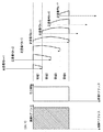
図13に示す入力DUTY分割テーブルの作成方法について、図15のフローチャートを用いて説明する。なお、入力DUTY分割テーブルの作成に先立って、図16に示すような、横サイズが入力画像の縦サイズ(1メモリは画像の縦方向の解像度に相当)であり、縦サイズが10(0〜1まで0.1刻みの格子)である領域を確保しておく。以下、この領域をテーブル領域と称し、横軸および縦軸の座標をそれぞれi,jとする。 A method of creating the input DUTY division table shown in FIG. 13 will be described with reference to the flowchart of FIG. Prior to the creation of the input DUTY division table, as shown in FIG. 16, the horizontal size is the vertical size of the input image (one memory corresponds to the vertical resolution of the image), and the vertical size is 10 (0 to 0). An area which is a grid of 0.1 increments up to 1) is secured. Hereinafter, this area is referred to as a table area, and the coordinates of the horizontal axis and the vertical axis are i and j, respectively.
まず、同一記録領域を形成するパス数を決定する(S1501)。パス数は、印字モードや記録媒体に応じて決定されることが多い。本実施形態では、同一記録領域を4パス印字で形成していく場合を例として説明する。 First, the number of passes for forming the same recording area is determined (S1501). The number of passes is often determined according to the print mode and the recording medium. In the present embodiment, a case where the same recording area is formed by 4-pass printing will be described as an example.
4パス印字を行うためには、まず、図16に示すテーブル領域内を横方向に4つの領域に分割するが、この分割をステップS1502〜S1504において行う。 In order to perform four-pass printing, first, the table area shown in FIG. 16 is divided into four areas in the horizontal direction, and this division is performed in steps S1502 to S1504.
まず、第1領域を設定するための頂点をn個設定する(S1502)。この頂点の数について特に制限はなく、例えば、分割率を滑らかに変化させたい場合には点の数を増やすとよい。また、第1領域を設定するための頂点an(i_an,j_an)の値の範囲は、例えば4パス印字であれば、各パス間で記録データの差が大きくならないように、j座標幅の平均が所定値(例えば0.25)となるように設定するなどの工夫が考えられる。 First, n vertices for setting the first area are set (S1502). There is no particular limitation on the number of vertices. For example, when it is desired to smoothly change the division ratio, the number of points may be increased. Further, the range of the value of the vertex an (i_an, j_an) for setting the first area is, for example, the average of the j-coordinate widths so that the difference in the recording data does not increase between the passes if printing is performed with 4 passes. It is conceivable to devise such that the value is set to a predetermined value (for example, 0.25).
ここで図17に、第1領域を設定するための頂点a1〜a7を設定した例を示す。このとき、頂点anのi座標は下式を満たす。なお、nは第1領域を設定するための頂点数を示し、頂点a1のi座標は0とする。 Here, FIG. 17 shows an example in which vertices a1 to a7 for setting the first region are set. At this time, the i coordinate of the vertex an satisfies the following expression. Note that n indicates the number of vertices for setting the first region, and the i coordinate of the vertex a1 is 0.
i_a1<i_a2<…<i_an ・・・(16)
すなわち、i座標については式(16)を満たしつつ、j座標値を適宜設定する。このj座標値によって分割率が設定されるが、その詳細については後述する。
i_a1 <i_a2 <... <i_an (16)
That is, for the i coordinate, the j coordinate value is appropriately set while satisfying the equation (16). The division ratio is set by the j coordinate value, and details thereof will be described later.
次に、第2領域の頂点をn'個設定する(S1503)。なお、この頂点の数についても特に制限はなく、例えば、分割率を滑らかに変化させたい場合は点の数を増やすとよい。 Next, n 'vertices in the second area are set (S1503). The number of vertices is not particularly limited. For example, when the division ratio is to be changed smoothly, the number of points may be increased.
第2領域の頂点を設定するにあたり、まず、その際に参照される値rn'(i_rn',j_rn')を設定する。この値rn'(i_rn',j_rn')は、i座標が第2領域の頂点のi座標を示し、j座標は第2領域の頂点から第1領域への距離を示し、以下のように設定される。まず、i座標について、下式を満たす。 In setting the vertices of the second region, first, values rn ′ (i_rn ′, j_rn ′) to be referred to at that time are set. This value rn ′ (i_rn ′, j_rn ′) is the i coordinate indicating the i coordinate of the vertex of the second region, the j coordinate indicating the distance from the vertex of the second region to the first region, and is set as follows: Is done. First, the following formula is satisfied for the i coordinate.
i_r1<i_r2<…<i_rn' ・・・(17)
そしてrn'におけるj座標の範囲については、例えば4パス印字であれば、各パス間で記録データの差が大きくならないように、j座標幅の平均が所定値(例えば0.25)となるように設定するなどの工夫が考えられる。
i_r1 <i_r2 <... <i_rn '(17)
As for the range of the j coordinate at rn ′, for example, in the case of 4-pass printing, the average of the j-coordinate width is set to a predetermined value (for example, 0.25) so that the difference in recording data between the passes does not increase. It is possible to devise such as setting to.
次に、第2領域を設定するための頂点bn'(i_bn',j_bn')を、上記rn'を用いて以下の式(18),(19)により算出する。 Next, the vertex bn ′ (i_bn ′, j_bn ′) for setting the second region is calculated by the following equations (18) and (19) using the rn ′.
i_bn'=i_rn' ・・・(18)
j_bn'=j_rn'+j_a((n'-1)・n') ・・・(19)
ここで、式(18),(19)による頂点bn'の算出について、図18を用いて具体的に説明する。図18においては、既に設定されている第1領域の頂点a1とa2に基づき、第2領域の頂点b2を設定する例(上記式(18),(19)におけるn'=2に相当)を示す。同図においてb2(i_b2,j_b2)は、予め設定された値r2(i_r2,j_r2)に基づいて、まずi座標値i_b2=i_r2となる。そしてj座標値については、第1領域を形成する線分a2−a1上において、i座標がi_r2となる点a12(i_r2,j_a1・2)に基づき、j_b2=j_r2+j_a1・2となる。すなわち、式(19)におけるj_a(n'・(n'-1))は、点bn'から第1領域を形成する線分an−a(n-1)上でi座標がi_rn'となる点(図18ではa12)を、点anおよび点a(n-1)の線形補間により算出することによって得られる。
i_bn '= i_rn' (18)
j_bn ′ = j_rn ′ + j_a ((n′−1) · n ′) (19)
Here, the calculation of the vertex bn ′ by the equations (18) and (19) will be specifically described with reference to FIG. In FIG. 18, an example of setting the vertex b2 of the second region based on the vertices a1 and a2 of the first region already set (corresponding to n ′ = 2 in the above equations (18) and (19)). Show. In the figure, b2 (i_b2, j_b2) first becomes an i coordinate value i_b2 = i_r2 based on a preset value r2 (i_r2, j_r2). The j coordinate value is j_b2 = j_r2 + j_a1 · 2 based on the point a12 (i_r2, j_a1 · 2) where the i coordinate is i_r2 on the line segment a2−a1 forming the first region. That is, j_a (n ′ · (n′−1)) in the equation (19) has an i coordinate i_rn ′ on the line segment an−a (n−1) forming the first region from the point bn ′. The point (a12 in FIG. 18) is obtained by calculating by linear interpolation of the point an and the point a (n-1).
ここで図19に、第2領域を設定するための頂点b1〜b5を設定した例を示す。 Here, FIG. 19 shows an example in which vertices b1 to b5 for setting the second region are set.
そして、同様に第3領域用の頂点cnを設定する(ステップS1504)。図20に、第3領域を設定するための頂点c1〜c8の例を示す。またこのとき、残りの領域が第4領域として設定される。 Similarly, the vertex cn for the third region is set (step S1504). FIG. 20 shows an example of vertices c1 to c8 for setting the third region. At this time, the remaining area is set as the fourth area.
以上のようにテーブル領域を4分割することによって設定された第1〜第4領域はそれぞれ、4パス印字における第1〜第4パス目に形成される領域に対応する。 As described above, the first to fourth areas set by dividing the table area into four correspond to areas formed in the first to fourth passes in 4-pass printing, respectively.
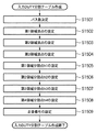
次に、第1〜第4領域のそれぞれについて、何走査目でいくつのノズルを使用するかを決定するために、各領域の分割点をステップS1505〜S1508において設定する。なお、各領域における分割点間の距離が使用ノズル数を示し、隣接する領域間における分割点の差が、紙送り量に相当する。 Next, for each of the first to fourth regions, division points for each region are set in steps S1505 to S1508 in order to determine how many nozzles are used for which scan. The distance between division points in each region indicates the number of nozzles used, and the difference between division points between adjacent regions corresponds to the paper feed amount.
まず、第1領域を画像縦方向に複数の領域に分割するために、図21に示すように、第1領域を設定する線上に点h1nを設定し、そこからi軸方向に垂線を下ろす(S1505)。ここで、点h1n(i_h1n,j_h1n)は、式(20)で示す関係を示し、さらに各点の差△hは式(21)に示すように、ノズル長以下でなければならない。 First, in order to divide the first area into a plurality of areas in the vertical direction of the image, as shown in FIG. 21, a point h1n is set on a line for setting the first area, and a perpendicular line is dropped therefrom in the i-axis direction ( S1505). Here, the point h1n (i_h1n, j_h1n) indicates the relationship expressed by the equation (20), and the difference Δh between the points must be equal to or less than the nozzle length as shown in the equation (21).
i_h11<i_h12<…<i_h1n(nは頂点数) ・・・(20)
△h=|i_h1n−i_h1(n-1)|<Nzzl ・・・(21)
なぜなら、上述した図14からも分かるように、点h1nにより分割された複数の領域の幅△hは、その領域を記録するために使用されるノズル数に相当するためである。
i_h11 <i_h12 <... <i_h1n (n is the number of vertices) (20)
Δh = | i_h1n−i_h1 (n−1) | <Nzzl (21)
This is because the width Δh of the plurality of areas divided by the point h1n corresponds to the number of nozzles used for recording the area, as can be seen from FIG.
そして第2〜第4領域についても同様に、それぞれの領域分割点hを設定し、図22,図23に示すように、各領域をi軸方向に複数領域に分割する(S1506〜S1508)。 Similarly, for each of the second to fourth regions, each region dividing point h is set, and each region is divided into a plurality of regions in the i-axis direction as shown in FIGS. 22 and 23 (S1506 to S1508).
以上のように各領域が縦に分割されると、次に、領域分割点hから下ろした垂線で区分された複数の多角形領域に対して、走査番号を割り当てる(S1509)。ここでの走査番号の振り方の規則は以下の通りである。まず、第1領域の最も左についての走査番号を1とし、次に、その上にある多角形領域(第2領域の最も左)の走査番号を2とする。同様な規則で走査番号を順次付していくことにより、各領域には以下のような走査番号が付される。 When each region is vertically divided as described above, next, a scan number is assigned to a plurality of polygonal regions divided by perpendicular lines drawn from the region dividing point h (S1509). The rules for assigning scan numbers here are as follows. First, the scan number for the leftmost of the first area is set to 1, and then the scan number of the polygon area (leftmost of the second area) thereabove is set to 2. By sequentially assigning scan numbers according to the same rule, the following scan numbers are assigned to each region.
第1領域:走査番号(4n+1)
第2領域:走査番号(4n+2)
第3領域:走査番号(4n+3)
第4領域:走査番号(4n+4)
以上のように、同一記録領域を走査する回数と、各走査で使用する記録素子数に基づいて、図13に示すような入力DUTY分割テーブルが作成される。すなわち本実施形態においては、同一記録領域を走査する回数と、各走査で使用する記録素子数を任意に設定して、入力Duty分割テーブルを作成することができる。
First area: scanning number (4n + 1)
Second area: scanning number (4n + 2)
Third area: scanning number (4n + 3)
Fourth area: scanning number (4n + 4)
As described above, an input DUTY division table as shown in FIG. 13 is created based on the number of times the same recording area is scanned and the number of recording elements used in each scan. That is, in this embodiment, the input duty division table can be created by arbitrarily setting the number of times of scanning the same printing area and the number of printing elements used in each scan.
以下、入力DUTY分割テーブルにおける設定内容について、詳細に説明する。 Hereinafter, the setting contents in the input DUTY division table will be described in detail.
上述した図14は、入力DUTY分割テーブルに対して、各走査において使用するノズルと画像上の記録領域の関係を示している。 FIG. 14 described above shows the relationship between the nozzles used in each scan and the recording area on the image with respect to the input DUTY division table.
図14によれば例えば、入力画像の主走査方向における記録領域Aは、走査番号k=1において下端1/2ノズルが使用され、ノズル1/4分の紙送り後、走査番号k=2が走査される。そしてノズル1/8分の紙送り後、走査番号=3が走査され・・・というように、順次走査がなされる。このとき、注目画素の分割率は入力DUTY分割テーブルのj軸の値によって決まる。
According to FIG. 14, for example, in the recording area A in the main scanning direction of the input image, the lower half nozzle is used at the scanning number k = 1, and after feeding the paper for the
例えば走査番号k=1において、各ノズルに対して、入力DUTYの分割率は図25の2501に示すように設定される。この場合すなわち、下端4ノズルn5〜n8について、i=0〜3に応じたj値で入力DUTYが割り当てられ、上端4ノズルn1〜n4についての割り当ては0である。なお、図25の例では、各領域の頂点間においては線形補間を行うことにより、分割率を0〜1の実数として算出している。
For example, at the scan number k = 1, the division ratio of the input DUTY is set as indicated by 2501 in FIG. 25 for each nozzle. In this case, the input DUTY is assigned with a j value corresponding to i = 0 to 3 for the
また、図25の2502,2503はそれぞれ、走査番号k=2,3における、各ノズルに対する入力DUTYの分割率を示す。例えば走査番号k=2の場合、2502に示すように、ノズルn1,n2については入力DUTYの割り当てはなく、他のノズルn3〜n8について、i=0〜5に応じたj値に基づき、入力DUTYが割り当てられている。このときの割り当て量は、j値から前回(走査番号k=1)の割り当て分を減じていることが分かる。走査番号k=3の場合も同様に、走査番号k=1,2の割り当て分が、j値より減じられて割り当てられる。 Also, 2502 and 2503 in FIG. 25 indicate the division ratios of the input DUTY for each nozzle at the scan numbers k = 2 and 3, respectively. For example, in the case of scan number k = 2, as indicated by 2502, there is no assignment of input DUTY for nozzles n1, n2, and the other nozzles n3-n8 are input based on j values corresponding to i = 0-5. DUTY is assigned. It can be seen that the allocation amount at this time is obtained by subtracting the previous allocation (scan number k = 1) from the j value. Similarly, in the case of scan number k = 3, the assignment of scan number k = 1, 2 is assigned by subtracting from the j value.
図25の2504に示す、走査番号k=4における各ノズルに対する入力DUTYの分割率は、同一領域での各パスでの分割率の合計が1となるように、走査番号k=1,2,3における分割率の和を1から減じることによって算出する。よって、記録パス数が4パスの場合は、同一領域の走査において、走査番号k=(4n+4)の分割率は、走査番号k=(4n+1),k=(4n+2),k=(4n+3)の和を1から減じることによって算出される。これにより、分割後のDUTYの和が、入力DUTYに等しくなる。 The division ratio of the input DUTY for each nozzle at the scan number k = 4 shown in 2504 of FIG. 25 is such that the total of the division ratios in each pass in the same region is 1, the scan numbers k = 1, 2, 3 is calculated by subtracting the sum of the division ratios at 3. Therefore, when the number of print passes is 4, the division ratio of the scan number k = (4n + 4) in the scan of the same area is as follows: scan number k = (4n + 1), k = (4n + 2), k = (4n + 3). Calculated by subtracting the sum from 1. Thereby, the sum of the divided DUTY becomes equal to the input DUTY.
ここで図26に、図14に示す入力DUTY分割テーブルに基づく、走査番号k=5〜8に対応した入力DUTY分割率の設定例を示す。図26についても図25と同様に、各パスに分割率が割り当てられる。 FIG. 26 shows a setting example of the input DUTY division ratio corresponding to the scan numbers k = 5 to 8 based on the input DUTY division table shown in FIG. Also in FIG. 26, as in FIG. 25, a division ratio is assigned to each path.
本実施形態では4パスによるマルチパス印字を行うため、走査番号k=1〜4,5〜8等、4つの走査番号ごとに、分割後の走査DUTYの和が入力DUTYに等しくなる。 In this embodiment, multi-pass printing is performed with four passes, so that the sum of the divided scan DUTY is equal to the input DUTY for every four scan numbers such as scan numbers k = 1 to 4, 5-8.
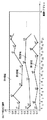
さらに、紙送り量LF(k)が、各領域内の分割点hの差によって算出される。図24に、入力DUTY分割テーブルによって設定される、各走査後の紙送り量LF(k)を示す。図24においては、矢印の方向に紙送りが行われ、例えば、走査番号k=1の走査後の紙送り量は、図22に示すh11とh12の差に応じてLF(1)=2となる。図24からも分かるように、本実施形態では、各走査後の紙送り量LF(k)が変化し、すなわち紙送り量LF(k)は一定の周期性を有さない。 Further, the paper feed amount LF (k) is calculated from the difference between the division points h in each region. FIG. 24 shows the paper feed amount LF (k) after each scan set by the input DUTY division table. In FIG. 24, paper feeding is performed in the direction of the arrow. For example, the paper feeding amount after scanning with the scanning number k = 1 is LF (1) = 2 according to the difference between h11 and h12 shown in FIG. Become. As can be seen from FIG. 24, in this embodiment, the paper feed amount LF (k) after each scan changes, that is, the paper feed amount LF (k) does not have a constant periodicity.
本実施形態における記録データ設定用LUT106は、上述した方法により作成された入力DUTY分割テーブルに基づき、各走査番号kごとに算出された以下の3項目の値が格納される。すなわち、1)色分解データ切り出し位置Ycut(k)、2)各ノズルに対する入力データの分割率、そして、3)走査後の紙送り量LF(k)である。
The print
以上例示したように、図14に示す入力DUTY分割テーブルに基づいて図25に示すような割り当てが行われることにより、上述した図7に示すように、記録データ設定用LUT106に分割率が設定される。
As illustrated above, the allocation as shown in FIG. 25 is performed based on the input DUTY division table shown in FIG. 14, so that the division ratio is set in the recording
入力DUTY分割テーブル及び記録データ設定用LUT106は、印字処理毎にリアルタイムに作成してもよいが、最終画像が高画質になるように、予め最適化された形で作成しておいても良い。印字処理毎に作成する場合には、入力DUTY分割テーブルは、入力画像の縦サイズを取得したタイミングで作成すると良い。
The input DUTY division table and the recording
また、入力DUTY分割テーブル作成時には、図16に示す格子点数のメモリ領域を確保してテーブルを作成してもよいが、領域分割点のデータをランダムに発生させてそれらの関係をポインタで示すことも可能である。この場合、記録データ設定用LUT106は、領域分割点aからdおよびhのi座標と前後の走査番号の関係を格納することによって作成される。
When creating the input DUTY division table, the table may be created by securing the memory area having the number of grid points shown in FIG. 16, but the data of the area division points is randomly generated and their relationship is indicated by the pointer. Is also possible. In this case, the recording
以上で、本実施形態における入力DUTY分割テーブルについての説明を終了する。 Above, description about the input DUTY division | segmentation table in this embodiment is complete | finished.
図3に戻り、ステップS105で記録データ格納メモリ107に記録データが格納されると、次にハーフトーン処理部108において、記録データ格納メモリ107に格納された記録データを、より少ない階調数に変換するハーフトーン処理を行う(S106)。ここでは、入力画像の各画素データの階調値を8ビットとし、ハーフトーン処理後には2レベルの階調値(2値データ)に変換する。
Returning to FIG. 3, when the recording data is stored in the recording
本実施形態におけるハーフトーン処理は、多値の入力画像データを2値画像に変換する処理として、例えば周知の誤差拡散法を用いる。以下、本実施形態におけるハーフトーン処理について、図27のフローチャートと図29のブロック図を用いて詳細に説明するが、説明を簡略化するため、4パス印字、走査番号k=1におけるシアンのハーフトーン処理を例として説明する。図27はハーフトーン処理部108におけるハーフトーン処理の詳細を示すフローチャートであり、図29は、ハーフトーン処理部108の詳細構成を示すブロック図である。
In the halftone process in the present embodiment, for example, a known error diffusion method is used as a process for converting multi-valued input image data into a binary image. Hereinafter, the halftone process according to the present embodiment will be described in detail with reference to the flowchart of FIG. 27 and the block diagram of FIG. 29. To simplify the description, the half-process of cyan in four-pass printing and scan number k = 1 is described. A tone process will be described as an example. FIG. 27 is a flowchart showing details of the halftone processing in the
まず図27に示すステップS201において、シアンの記録データC_dをハーフトーン処理部108に入力する。 First, in step S201 shown in FIG. 27, cyan recording data C_d is input to the halftone processing unit.
次にステップS202において、誤差拡散処理用に累積誤差を加算する。以下、累積誤差の加算処理について詳細に説明する。 In step S202, the accumulated error is added for error diffusion processing. The cumulative error adding process will be described in detail below.
本実施形態においては、誤差拡散処理のための誤差拡散係数として、図28に示すようにK1〜K4の4つの係数を持つとする。例えば、K1=7/16、K2=3/16、K3=5/16、K4=1/16とする。ただし、拡散係数は上記のように固定とする必要はなく、階調に応じて(例えばC_dに応じて)変更させても良いし、上記4係数に限らずさらに多くの係数を持たせても良い。 In this embodiment, it is assumed that there are four coefficients K1 to K4 as error diffusion coefficients for error diffusion processing as shown in FIG. For example, K1 = 7/16, K2 = 3/16, K3 = 5/16, and K4 = 1/16. However, the diffusion coefficient does not need to be fixed as described above, and may be changed according to the gradation (for example, according to C_d), or may be more than the above four coefficients. good.
このような誤差拡散係数により誤差を拡散、累積するために、ハーフトーン処理部108では累積誤差ラインバッファをシアンに対して4組確保し(2902〜2905)、使用する累積誤差ラインバッファを走査番号ごとに、例えば以下のように切り替える。
In order to diffuse and accumulate errors using such an error diffusion coefficient, the
「走査番号k=1,5,・・・,4n+1(nは0以上の整数)のとき」
(4n+1)累積誤差ラインバッファ2902を使用
「走査番号k=2,6,・・・,4n+2のとき」
(4n+2)累積誤差ラインバッファ2903を使用
「走査番号k=3,7,・・・,4n+3のとき」
(4n+3)累積誤差ラインバッファ2904を使用
「走査番号k=4,8,・・・,4n+4のとき」
(4n+4)累積誤差ラインバッファ2905を使用
なお、各累積誤差ラインバッファ2902,2903,2904,2905はそれぞれ、図30の3001〜3004に示す4組の記憶領域からなる。すなわち、「E1_0,E1(x)」、「E2_0,E2(x)」、「E3_0,E3(x)」、「E4_0,E4(x)」の4組である。例えば、(4n+1)累積誤差ラインバッファ2902は、1個の記憶領域E1_0と、入力画像の横画素数Wと同数の記憶領域E1_(x)(x=1〜W)を有する。また、各累積誤差ラインバッファ2902,2903,2904,2905はそれぞれ、走査番号k=1,2,3,4の処理開始時のみ、全て初期値0で初期化されている。例えば走査番号k=5の処理開始時には、(4n+1)累積誤差ラインバッファ2902は初期化されない。
“When scan number k = 1, 5,..., 4n + 1 (n is an integer of 0 or more)”
(4n + 1) Use cumulative
(4n + 2) Use cumulative error line buffer 2903 “when scan number k = 3, 7,..., 4n + 3”
(4n + 3) Use cumulative error line buffer 2904 "when scan number k = 4, 8, ..., 4n + 4"
(4n + 4) Cumulative
本実施形態では、1色のハーフトーン処理について、上述した4組の累積誤差ラインバッファが必要になるため、これを6色分用意する必要がある。すなわち、合計4×6=24組のラインバッファが必要になる。 In the present embodiment, since the four sets of accumulated error line buffers described above are required for halftone processing of one color, it is necessary to prepare these for six colors. That is, a total of 4 × 6 = 24 sets of line buffers are required.
ここでは、走査番号k=1についてのハーフトーン処理を例として説明するため、(4n+1)累積誤差ラインバッファ2902を使用して誤差拡散処理を実施するとする。すなわちステップS202では、累積誤差加算部2906において、入力された記録データ値に対して、入力データの横画素位置xに対応する誤差E1(x)が加算される。即ち、入力された注目画素の記録データをC_d、累積誤差加算後のデータをC_d'とすると、以下の式が成り立つ。
Here, in order to explain halftone processing for scan number k = 1 as an example, it is assumed that error diffusion processing is performed using (4n + 1) cumulative
C_d'=C_d+E1(x) ・・・(22)
次にステップS203において、閾値選択部2907は閾値Tを選択する。閾値Tは、例えば以下のように設定される。
C_d ′ = C_d + E1 (x) (22)
In step S203, the
T=128 ・・・(23)
或いは、ドット生成遅延を回避するため、平均量子化誤差が小さくなるよう、入力された注目画素の記録データC_dに応じて閾値Tを以下のように細かく変更しても良い。
T = 128 (23)
Alternatively, in order to avoid dot generation delay, the threshold value T may be finely changed as follows according to the input recording data C_d of the target pixel so that the average quantization error is reduced.
T=f(C_d) ・・・(24)
或いは、バンド内のアドレス(X、Y)に応じて、以下のように細かく変更しても良い。
T = f (C_d) (24)
Or according to the address (X, Y) in a band, you may change finely as follows.
T=f(X,Y) ・・・(25)
次にステップS204において、量子化部2908は、誤差加算後の画素データC_d'と閾値Tを比較し、ドットの2値化処理の結果であるOut_cを決定する。その規則は次の通りである。
T = f (X, Y) (25)
Next, in step S204, the
C_d'<Tのとき、
Out_c=0 ・・・(26)
C_d'≧Tのとき、
Out_c=255 ・・・(27)
次にステップS205において、誤差演算部2909は、注目画素の記録データC_dに誤差を加算した画素データC_d'と、出力画素値Out_cとの差分Errを、次のように算出する。
When C_d ′ <T,
Out_c = 0 (26)
When C_d ′ ≧ T,
Out_c = 255 (27)
In step S205, the
Err(x)=C_d'−Out_c ・・・(28)
次にステップS206において、誤差拡散部2910が誤差を拡散する。即ち、(4n+1)累積誤差ラインバッファ2902を用いて、横画素位置xに応じた誤差Err(x)の拡散処理が、以下のように行われる。
Err (x) = C_d′−Out_c (28)
In step S206, the
E1(x+1)←E1(x+1)+Err(x)×7/16 (x<W)
E1(x−1)←E1(x−1)+Err(x)×3/16 (x>1)
E1(x)←E1_0+Err(x)×5/16 (1<x<W)
E1(x)←E1_0+Err(x)×8/16 (x=1)
E1(x)←E1_0+Err(x)×13/16 (x=W)
E1_0←Err(x)×1/16 (x<W)
E1_0←0 (x=W)
・・・(29)
以上で、走査番号k=1のシアン1画素分の2値化処理(量子化値0,255)が完了する。
E1 (x + 1) ← E1 (x + 1) + Err (x) × 7/16 (x <W)
E1 (x-1) ← E1 (x-1) + Err (x) × 3/16 (x> 1)
E1 (x) ← E1_0 + Err (x) × 5/16 (1 <x <W)
E1 (x) ← E1_0 + Err (x) × 8/16 (x = 1)
E1 (x) ← E1_0 + Err (x) × 13/16 (x = W)
E1_0 ← Err (x) × 1/16 (x <W)
E1_0 ← 0 (x = W)
... (29)
This completes the binarization process (quantized
以上説明したステップS201〜S206の処理を、バンド内の全ての画素(アドレス(0,0)〜(W−1,Nzzl−1))について行う(S207)ことにより、ハーフトーン画像データを生成することができる。 The processes in steps S201 to S206 described above are performed for all the pixels in the band (address (0, 0) to (W-1, Nzzl-1)) (S207), thereby generating halftone image data. be able to.
なお、以上は走査番号k=1について説明したが、走査番号k=2〜4については、それぞれの累積誤差ラインバッファ2903〜2905を用いて上記ハーフトーン処理を行う。走査番号k=5の処理では、走査番号k=1と同じ(4n+1)累積誤差ラインバッファ2902を、初期化せずに(全0を代入せずに)そのまま用いる。これは図14に示すように、走査番号k=1と走査番号k=5の印字領域が上下に隣接しているため、保存されている累積誤差をそのまま、隣接下の領域に適用するためである。もしも、k=5で累積誤差ラインバッファ2902を初期化すると、k=1と隣接する境界部で誤差が保存されなくなり、ドットの連続性が保てなくなってしまう。
The scan number k = 1 has been described above. However, for the scan numbers k = 2 to 4, the halftone process is performed using the accumulated error line buffers 2903 to 2905. In the process of scan number k = 5, the same (4n + 1) cumulative
図3に戻り、以上説明したようにステップS106におけるハーフトーン処理が終了すると、次に、ハーフトーン処理後の2値画像データはハーフトーン画像格納メモリ109に格納される(S107)。ここで図31に、走査番号k=1の記録データをハーフトーン処理した結果が、ハーフトーン画像格納メモリ109に格納された様子を示す。同図に示されるようにハーフトーン画像格納メモリ109には、記録データの画素位置に対応する(ノズル数:Nzzl)×(画像Xサイズ:W)分の2値画像データが格納される。
Returning to FIG. 3, when the halftone process in step S106 is completed as described above, the binary image data after the halftone process is stored in the halftone image storage memory 109 (S107). Here, FIG. 31 shows a state in which the result of halftone processing of the print data of scan number k = 1 is stored in the halftone
なお、図31からも分かるように、本実施形態におけるハーフトーン処理は、縦がノズル数、横が画像Xサイズである記録データ格納メモリ107に格納されたデータに対し、順次2値画像データを生成していく。したがって、ハーフトーン画像格納メモリ109も同様に、縦ノズル数、横画像Xサイズのバンドデータ分のメモリ空間を用意したものである。
As can be seen from FIG. 31, the halftone process in the present embodiment sequentially outputs binary image data with respect to the data stored in the recording
以上により、走査番号k=1でのハーフトーン処理が終了し、その結果、各色分の一回のヘッド動作で形成される2値画像が、各色分のハーフトーン画像格納メモリ109に格納されることになる。
As described above, the halftone process at the scan number k = 1 is completed, and as a result, a binary image formed by one head operation for each color is stored in the halftone
なお、本実施形態のハーフトーン処理部108における量子化手法は、上述した誤差拡散法に限らず、例えばブルーノイズマスク系やベイヤ系のディザ法、濃度パターン法を利用してもよい。あるいは、これら複数の方法を組み合わせて利用してもよい。
The quantization method in the
次に、ハーフトーン画像格納メモリ109に蓄えられた、縦方向がノズル数(Nzzl)、横方向が画像のXサイズ(W)に相当するバンドデータが、画像出力端子112より出力される(S108)。
Next, band data corresponding to the number of nozzles (Nzzl) in the vertical direction and the X size (W) of the image in the horizontal direction stored in the halftone
ハーフトーンの画像データを受けたプリンタ2では、該画像データをハーフトーン画像格納メモリ207に格納する。そして、該画像データに適合するインク色および吐出量がインク色及び吐出量選択部206で選択され、印字動作が開始される(S109)。この印字動作においては、記録ヘッド201が記録媒体に対して左から右に移動しながら、一定の駆動間隔で各ノズルを駆動して記録媒体上に画像を記録する。なお、本実施形態では、記録媒体上で記録ヘッド201によって複数回の走査を行って画像を完成させるマルチパス記録方式を用いている。
The
そして、全ての走査が終了したか否かの判定を行う(S110)。終了した場合には一連の画像形成処理が完了し、終了していない場合にはステップS103に戻る。以上により、多階調のカラー入力画像データに対する一連の画像形成処理が完了する。 Then, it is determined whether or not all scanning has been completed (S110). If completed, a series of image forming processes are completed, and if not completed, the process returns to step S103. Thus, a series of image forming processes for multi-tone color input image data is completed.
以上説明したように本実施形態によれば、マルチパス印字において、各走査で使用する記録素子数すなわち記録媒体の搬送量を任意に設定することができる。これにより、記録素子のバラツキによる濃度ムラおよび紙送りずれによる粒状性の悪化と長周期の濃度ムラを低減し、記録媒体全面で高画質を実現することが可能である。 As described above, according to the present embodiment, in multi-pass printing, the number of recording elements used in each scan, that is, the conveyance amount of the recording medium can be arbitrarily set. Accordingly, it is possible to reduce the density unevenness due to the variation of the recording elements, the deterioration of the graininess due to the paper feed deviation and the long-period density unevenness, and to realize high image quality on the entire surface of the recording medium.
<第2実施形態>
以下、本発明に係る第2実施形態について説明する。
Second Embodiment
Hereinafter, a second embodiment according to the present invention will be described.
上述した第1実施形態では、マルチパス記録方式において、画像の主走査方向の記録領域を完成させるパス数が一定(例えば4パス)である場合について説明した。第2実施形態においては、このパス数を可変とする例を示す。なお、第2実施形態における画像形成装置の構成は、上述した第1実施形態と同様であるため、説明を省略する。 In the first embodiment described above, a case has been described in which the number of passes for completing a recording area in the main scanning direction of an image is constant (for example, four passes) in the multi-pass printing method. The second embodiment shows an example in which the number of paths is variable. Note that the configuration of the image forming apparatus according to the second embodiment is the same as that of the first embodiment described above, and a description thereof will be omitted.
第2実施形態におけるパス数は、入力DUTY分割テーブルによって制御される。すなわち第2実施形態においては、入力DUTY分割テーブルに対してパス数を設定可能とすることを特徴とする。 The number of paths in the second embodiment is controlled by the input DUTY division table. That is, the second embodiment is characterized in that the number of passes can be set for the input DUTY division table.
図32に、第2実施形態で作成される入力DUTY分割テーブル例を示す。この入力DUTY分割テーブルに基づいて、図33に示す記録データ設定用LUT106が作成される。すなわち第2実施形態においては、図33に示す記録データ設定用LUT106に、図32に示す入力DUTY分割テーブルに設定されたパス数の情報が含まれている。
FIG. 32 shows an example of an input DUTY division table created in the second embodiment. Based on the input DUTY division table, a recording
図32において、横軸は入力画像の縦画素位置i(Yアドレス)、縦軸は注目画素の画素値(入力DUTY)について各パスでの相対分割率jを示し、さらに、テーブル内の線分で区切られた領域内の数字は、走査番号kを示している。このテーブルにより、注目画素I(X,Y)が記録される走査番号k、および概走査で記録される記録率が決定される。 ここで図34に、図32に示す入力DUTY分割テーブルを使用した場合に、各走査において記録される領域と、使用されるノズルの対応例を示す。なお、図34によれば、上述した図14と同様に各走査における使用ノズルおよび紙送り量が示されるが、全ての領域について4パスによる画像形成が行われているわけではない。例えば、記録領域A〜Cは4パス形成されるが、記録領域D〜Hは5パス、記録領域Iは6パスによる画像形成がなされている。 In FIG. 32, the horizontal axis indicates the vertical pixel position i (Y address) of the input image, the vertical axis indicates the relative division ratio j in each pass for the pixel value of the target pixel (input DUTY), and a line segment in the table. The number in the area delimited by indicates the scan number k. Based on this table, the scan number k in which the target pixel I (X, Y) is recorded and the recording rate recorded in the approximate scan are determined. Here, FIG. 34 shows a correspondence example between the area to be recorded in each scan and the nozzle to be used when the input DUTY division table shown in FIG. 32 is used. FIG. 34 shows the used nozzles and the paper feed amount in each scan as in FIG. 14 described above, but image formation by four passes is not performed for all regions. For example, the recording areas A to C are formed by 4 passes, but the recording areas D to H are formed by 5 passes and the recording area I is formed by 6 passes.
以下、図32に示す入力DUTY分割テーブルを作成する方法について、図35のフローチャートを用いて説明する。なお、入力DUTY分割テーブルの作成に先立って、図16に示すような、横サイズが入力画像の縦サイズ(1メモリは画像の縦方向の解像度に相当)であり、縦サイズが10(0〜1まで0.1刻みの格子)である領域を確保しておく。以下、この領域をテーブル領域と称し、横軸および縦軸の座標をそれぞれi,jとする。 Hereinafter, a method of creating the input DUTY division table shown in FIG. 32 will be described with reference to the flowchart of FIG. Prior to the creation of the input DUTY division table, as shown in FIG. 16, the horizontal size is the vertical size of the input image (one memory corresponds to the vertical resolution of the image), and the vertical size is 10 (0 to 0). An area which is a grid of 0.1 increments up to 1) is secured. Hereinafter, this area is referred to as a table area, and the coordinates of the horizontal axis and the vertical axis are i and j, respectively.
まず、同一記録領域を形成する最小パス数と最大パス数を決定する(S3501)。パス数は、印字モードや記録媒体に応じて決定されることが多い。本実施形態では、同一記録領域を最小4パス、最大6パスによる印字で形成していく場合を例として説明する。 First, the minimum number of passes and the maximum number of passes that form the same recording area are determined (S3501). The number of passes is often determined according to the print mode and the recording medium. In this embodiment, a case where the same recording area is formed by printing with a minimum of 4 passes and a maximum of 6 passes will be described as an example.
そして、図16に示すテーブル領域内を横方向に、まず最小パス数分(すなわち4つ)の領域に分割するが、この分割をステップS3502〜S3505において行う。 Then, the table area shown in FIG. 16 is first divided into areas corresponding to the minimum number of paths (that is, four) in the horizontal direction. This division is performed in steps S3502 to S3505.
まず、第1領域を設定するための頂点をn個設定する(S3502)。この頂点の数について特に制限はなく、例えば、分割率を滑らかに変化させたい場合には点の数を増やすとよい。また、第1領域を設定するための頂点an(i_an,j_an)の値の範囲は、例えば4パス印字であれば、各パス間で記録データの差が大きくならないように、j座標幅の平均が所定値(例えば0.25)となるように設定するなどの工夫が考えられる。 First, n vertices for setting the first region are set (S3502). There is no particular limitation on the number of vertices. For example, when it is desired to smoothly change the division ratio, the number of points may be increased. Further, the range of the value of the vertex an (i_an, j_an) for setting the first area is, for example, the average of the j-coordinate widths so that the difference in the recording data does not increase between the passes if printing is performed with 4 passes. It is conceivable to devise such that the value is set to a predetermined value (for example, 0.25).
ここで図36に、第1領域を設定するための頂点a1〜a7の設定例を示す。このとき、頂点anのi座標は下式を満たす。なお、nは第1領域を設定するための頂点数を示し、頂点a1のi座標は0とする。 FIG. 36 shows an example of setting the vertices a1 to a7 for setting the first region. At this time, the i coordinate of the vertex an satisfies the following expression. Note that n indicates the number of vertices for setting the first region, and the i coordinate of the vertex a1 is 0.
i_a1<i_a2<…<i_an ・・・(30)
すなわち、i座標については式(16)を満たしつつ、j座標値を適宜設定する。
i_a1 <i_a2 <... <i_an (30)
That is, for the i coordinate, the j coordinate value is appropriately set while satisfying the equation (16).
次に、第2領域の頂点をn'個設定する(S3503)。なお、この頂点の数についても特に制限はなく、例えば、分割率を滑らかに変化させたい場合は点の数を増やすとよい。 Next, n 'vertices in the second area are set (S3503). The number of vertices is not particularly limited. For example, when the division ratio is to be changed smoothly, the number of points may be increased.
第2領域の頂点を設定するにあたり、まず、その際に参照される値rn'(i_rn',j_rn')を設定する。この値rn'(i_rn',j_rn')は、i座標が第2領域の頂点のi座標を示し、j座標は第2領域の頂点から第1領域への距離を示し、以下のように設定される。まず、i座標について、下式を満たす。 In setting the vertices of the second region, first, values rn ′ (i_rn ′, j_rn ′) to be referred to at that time are set. This value rn ′ (i_rn ′, j_rn ′) is the i coordinate indicating the i coordinate of the vertex of the second region, the j coordinate indicating the distance from the vertex of the second region to the first region, and is set as follows: Is done. First, the following formula is satisfied for the i coordinate.
i_r1<i_r2<…<i_rn' ・・・(31)
そしてrn'におけるj座標の範囲については、例えば4パス印字であれば、各パス間で記録データの差が大きくならないように、j座標幅の平均が所定値(例えば0.25)となるように設定するなどの工夫が考えられる。
i_r1 <i_r2 <... <i_rn '(31)
As for the range of the j coordinate at rn ′, for example, in the case of 4-pass printing, the average of the j-coordinate width is set to a predetermined value (for example, 0.25) so that the difference in recording data between the passes does not increase. It is possible to devise such as setting to.
次に、第2領域を設定するための頂点bn'(i_bn',j_bn')を、上記rn'を用いて以下の式(32),(33)により算出する。 Next, the vertex bn ′ (i_bn ′, j_bn ′) for setting the second region is calculated by the following equations (32) and (33) using the rn ′.
i_bn'=i_rn' ・・・(32)
j_bn'=j_rn'+j_a((n'-1)・n') ・・・(33)
なお、式(32),(33)による頂点bn'の算出については、上述した第1実施形態において図18を用いて説明したとおりであるため、ここでは詳細な説明を省略する。図36に、第2領域を設定するための頂点b1〜b5の設定例を示す。
i_bn '= i_rn' (32)
j_bn ′ = j_rn ′ + j_a ((n′−1) · n ′) (33)
Note that the calculation of the apex bn ′ by the equations (32) and (33) is as described with reference to FIG. 18 in the first embodiment, and therefore detailed description thereof is omitted here. FIG. 36 shows an example of setting the vertices b1 to b5 for setting the second region.
そして、同様に第3領域用の頂点cnを設定し(S3504)、さらに第4領域用の頂点dnを設定する(S3505)。図36に、第3領域を設定するための頂点c1〜c7、および第4領域を設定するための頂点d1〜d4の設定例を示す。 Similarly, the vertex cn for the third region is set (S3504), and the vertex dn for the fourth region is further set (S3505). FIG. 36 shows an example of setting the vertices c1 to c7 for setting the third region and the vertices d1 to d4 for setting the fourth region.
ここまでが、画像全体において同一記録領域内を最低4回の走査で形成するための、テーブル領域の分割である。 Up to this point, the table area is divided to form the same recording area in the entire image by at least four scans.
次に、同一記録領域内を5回以上の走査で形成するために、図36に示すテーブル領域をさらに分割する。すなわち、第5領域を設定するための頂点en(i_en,j_en)を、下記の条件に従って決定する(S3506)。なお、nは第5領域を設定するための頂点数を示す。 Next, the table area shown in FIG. 36 is further divided in order to form the same recording area in five or more scans. That is, the vertex en (i_en, j_en) for setting the fifth region is determined according to the following conditions (S3506). Note that n indicates the number of vertices for setting the fifth area.
0<i_e1<i_e2<…<i_en ・・・(34)
j_e1=1.0 ・・・(35)
図36に、第5領域を設定するための頂点e1〜e3の設定例を示す。
0 <i_e1 <i_e2 <... <i_en (34)
j_e1 = 1.0 (35)
FIG. 36 shows an example of setting the vertices e1 to e3 for setting the fifth region.
このように第5領域が設定されることにより、残りの領域が第6領域として設定される。 By setting the fifth area in this way, the remaining area is set as the sixth area.
以上のように領域の横6分割が終了すると、次に、各領域を何走査目で記録するかを決定するために、各領域の分割点をステップS3507〜S3512において設定する。 When the horizontal division of the area is completed as described above, the division point of each area is set in steps S3507 to S3512 in order to determine how many scans each area is to be recorded.
まず、第1領域を画像縦方向に複数の領域に分割するために、図21に示すように、第1領域を設定する線上に点h1nを設定し、そこからi軸方向に垂線を下ろす(S3507)。ここで、点h1n(i_h1n,j_h1n)は、式(36)で示す関係を示し、さらに各点の差△hは式(37)に示すように、ノズル長以下でなければならない。」
i_h11<i_h12<…<i_h1n(nは頂点数) ・・・(36)
△h=|i_h1n−i_h1(n-1)|<Nzzl ・・・(37)
なぜなら、上述した図34からも分かるように、点h1nにより分割された複数の領域の幅△hは、その領域を記録するために使用されるノズル数に相当するためである。
First, in order to divide the first area into a plurality of areas in the vertical direction of the image, as shown in FIG. 21, a point h1n is set on a line for setting the first area, and a perpendicular line is dropped therefrom in the i-axis direction ( S3507). Here, the point h1n (i_h1n, j_h1n) indicates the relationship represented by the equation (36), and the difference Δh between the points must be equal to or less than the nozzle length as represented by the equation (37). "
i_h11 <i_h12 <... <i_h1n (n is the number of vertices) (36)
Δh = | i_h1n−i_h1 (n−1) | <Nzzl (37)
This is because the width Δh of the plurality of areas divided by the point h1n corresponds to the number of nozzles used for recording the area, as can be seen from FIG.
そして第2〜第6領域についても同様に、それぞれの領域分割点hを設定し、図37に示すように、各領域をi軸方向に複数領域に分割する(S3508〜S3512)。 Similarly, for each of the second to sixth regions, each region dividing point h is set, and each region is divided into a plurality of regions in the i-axis direction as shown in FIG. 37 (S3508 to S3512).
以上のように各領域が縦に分割されると、次に、領域分割点hから下ろした垂線で区分された複数の多角形領域に対して、走査番号を割り当てる(S3513)。ここでの走査番号の振り方の規則は、上述した第1実施形態と同様に、第1領域の左下から上方向へ順次、走査番号が付されていくことにより、各領域には図32のように走査番号が付される。 When each region is vertically divided as described above, next, a scanning number is assigned to a plurality of polygonal regions divided by a perpendicular drawn from the region dividing point h (S3513). The rule for assigning the scan numbers here is the same as in the first embodiment described above. By sequentially assigning the scan numbers from the lower left of the first area to the upper direction, each area shown in FIG. The scan number is assigned as follows.
以上の方法により、図32に示すような入力DUTY分割テーブルが作成され、該テーブルにより、画像の記録領域を完成させる主走査方向のパス数を変化させることができる。図32に示す入力DUTY分割テーブルに基づく図34によれば、記録領域A〜Cは4パスで、記録領域D〜Hは5パス、記録領域Iは6パスによる印字が行われており、ステップS3501で設定された最小パス数4および最大パス数6が満たされている。
With the above method, an input DUTY division table as shown in FIG. 32 is created, and the number of passes in the main scanning direction for completing an image recording area can be changed using the table. According to FIG. 34 based on the input DUTY division table shown in FIG. 32, the recording areas A to C are printed in 4 passes, the recording areas D to H are printed in 5 passes, and the recording area I is printed in 6 passes. The minimum number of
次に、第2実施形態における紙送り量について説明する。 Next, the paper feed amount in the second embodiment will be described.
図38に、第2実施形態の入力DUTY分割テーブルに基づいて設定される、各走査後の紙送り量LF(k)を示す。図38においては、矢印の方向に紙送りが行われ、例えば、走査番号k=1の走査後の紙送り量はLF(1)=1となる。図38からも分かるように、第2実施形態では、各走査後の紙送り量LF(k)が変化し、すなわち紙送り量LF(k)は一定の周期性を有さない。 FIG. 38 shows the paper feed amount LF (k) after each scan, which is set based on the input DUTY division table of the second embodiment. In FIG. 38, the paper is fed in the direction of the arrow. For example, the paper feed amount after scanning with the scan number k = 1 is LF (1) = 1. As can be seen from FIG. 38, in the second embodiment, the paper feed amount LF (k) after each scan changes, that is, the paper feed amount LF (k) does not have a constant periodicity.
第2実施形態における記録データ設定用LUT106は、上述した方法により作成された入力DUTY分割テーブルに基づき、各走査番号kごとに、以下の項目の値が格納される。すなわち図33に示すように、まず第1実施形態と同様に、1)色分解データ切り出し位置Ycut(k)、2)各ノズルに対する入力データの分割率、そして、3)走査後の紙送り量LF(k)が格納される。さらに第2実施形態においては、後述する誤差拡散処理において参照される累積誤差バッファ番号が、4)隣接領域番号Lとして格納される。
The print
同一記録領域を形成するパス数が一定の場合には、上述した第1実施形態で示したように、例えば走査番号k=1と走査番号k=5の印字領域が上下に隣接している(図14参照)。そのため、累積誤差を隣接下の領域へ保存させるために、誤差拡散処理に使用する誤差バッファを走査番号に応じて選択することが可能であった。 When the number of passes forming the same recording area is constant, as shown in the first embodiment described above, for example, the printing areas of scanning number k = 1 and scanning number k = 5 are adjacent vertically ( (See FIG. 14). Therefore, in order to save the accumulated error in the adjacent area, it is possible to select an error buffer used for error diffusion processing according to the scan number.
しかしながら第2実施形態では、画像内で同一記録領域を形成するパス数が局所的に変化するため、累積誤差を保存させる領域はパス数に依存しない。そのため、入力DUTY分割テーブルにおいて、隣接する領域、すなわち累積誤差を保存させる領域の走査番号kを、「隣接領域番号L」として記憶しておき、誤差拡散処理での誤差バッファの選択の際に参照する。 However, in the second embodiment, since the number of passes forming the same recording area in the image locally changes, the area for storing the accumulated error does not depend on the number of passes. Therefore, in the input DUTY division table, the scan number k of the adjacent region, that is, the region in which the accumulated error is stored is stored as “adjacent region number L” and is referred to when selecting the error buffer in the error diffusion process. To do.
以上で、第2実施形態における入力DUTY分割テーブルの作成方法についての説明を終了する。 This is the end of the description of the method of creating the input DUTY division table in the second embodiment.
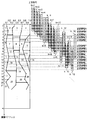
なお、第2実施形態の特徴である、入力DUTY分割テーブルに対してパス数を設定可能とする方法は、上述した手法に限らない。例えば、以下に示すようなドロネー三角分割を用いた手法も適用可能である。 Note that the method of enabling the number of passes to be set for the input DUTY division table, which is a feature of the second embodiment, is not limited to the method described above. For example, a technique using Delaunay triangulation as shown below is also applicable.
例えば、入力DUTY分割テーブルの領域を設定する頂点を図56に示すようにランダムに発生させ、これらの点集合に対してドロネー三角分割を行うことにより、図57に示すように三角形の辺を構成する。次に、下記の2つの規則により、矩形領域を複数の多角形の領域に分割する。 For example, vertices for setting the area of the input DUTY division table are randomly generated as shown in FIG. 56, and Delaunay triangulation is performed on these point sets to form triangle sides as shown in FIG. To do. Next, the rectangular area is divided into a plurality of polygonal areas according to the following two rules.
(1)原点Aに最も近い点(図57ではV1)と原点Aを結ぶ。 (1) The point closest to the origin A (V1 in FIG. 57) is connected to the origin A.
(2)閉曲線を構成する点から、テーブル領域の下辺および上辺に垂線を下ろす。 (2) Draw perpendicular lines to the lower and upper sides of the table area from the points constituting the closed curve.
これにより、図58に示すように、テーブル領域が9つの領域に分割される。なお、矩形内の領域番号は、上述した方法と同様に走査番号に対応している。 Thereby, as shown in FIG. 58, the table area is divided into nine areas. Note that the region number in the rectangle corresponds to the scan number in the same manner as described above.
この方法を利用して入力DUTY分割テーブルを作成すると、各走査で使用する記録素子数と同一領域を走査する回数を、より柔軟に設定することが可能となる。 If an input DUTY division table is created using this method, the number of times of scanning the same area as the number of printing elements used in each scan can be set more flexibly.
すなわち第2実施形態において、同一領域を走査する回数と、その際に使用する記録素子を設定可能とするには、任意に設定した規則に基き、入力DUTY分割テーブルを複数の多角形領域に分割し、各多角形領域に走査番号を振れば良い。ただし、分割時には式(37)を必ず満たさなければならない。 That is, in the second embodiment, in order to be able to set the number of times the same area is scanned and the printing elements used at that time, the input DUTY division table is divided into a plurality of polygonal areas based on arbitrarily set rules. A scanning number may be assigned to each polygonal area. However, Expression (37) must be satisfied at the time of division.
次に、第2実施形態におけるハーフトーン処理について説明する。第2実施形態においても、上述した第1実施形態と同様に誤差拡散処理を行うが、その処理の詳細については図27に示したとおりであるため、ここでは説明を省略する。 Next, halftone processing in the second embodiment will be described. Also in the second embodiment, error diffusion processing is performed in the same manner as in the first embodiment described above. Details of the processing are as shown in FIG.
図39は、第2実施形態におけるハーフトーン処理部108の詳細構成を示す図である。第2実施形態における誤差拡散処理を実行するために、ハーフトーン処理部108は
累積誤差ラインバッファを最大パス数組確保する(3902〜3907)。そして、使用する累積誤差ラインバッファを、記録データ設定用LUTの「隣接領域番号L」の値に基づいて、例えば以下のように切り替える。
FIG. 39 is a diagram illustrating a detailed configuration of the
「隣接領域番号L=6n+1のとき」
(6n+1)累積誤差ラインバッファ3902を使用
「隣接領域番号L=6n+2のとき」
(6n+2)累積誤差ラインバッファ3903を使用
「隣接領域番号L=6n+3のとき」
(6n+3)累積誤差ラインバッファ3904を使用
「隣接領域番号L=6n+4のとき」
(6n+4)累積誤差ラインバッファ3905を使用
「隣接領域番号L=6n+5のとき」
(6n+5)累積誤差ラインバッファ3906を使用
「隣接領域番号L=6n+6のとき」
(6n+6)累積誤差ラインバッファ3907を使用
以上説明したように第2実施形態によれば、記録ヘッドの分割された領域を用いた走査により画像を形成する記録方式において、記録媒体上の同一領域に対して、画像形成を完成させるパス数を任意に設定することができる。すなわち、同一領域を走査する回数と、その際に使用する記録素子、走査後の記録媒体の搬送量の設定が可能となる。
“When adjacent area number L = 6n + 1”
(6n + 1) Use cumulative
(6n + 2) Use cumulative error line buffer 3903 “When adjacent area number L = 6n + 3”
(6n + 3) Use cumulative error line buffer 3904 “When adjacent area number L = 6n + 4”
(6n + 4) Use cumulative error line buffer 3905 “When adjacent area number L = 6n + 5”
(6n + 5) Use cumulative error line buffer 3906 “When adjacent area number L = 6n + 6”
Using (6n + 6) Cumulative Error Line Buffer 3907 As described above, according to the second embodiment, in the recording method for forming an image by scanning using the divided areas of the recording head, the same area on the recording medium is used. On the other hand, the number of passes for completing image formation can be arbitrarily set. That is, it is possible to set the number of times of scanning the same area, the recording element used at that time, and the transport amount of the recording medium after scanning.
これにより第2実施形態によれば、第1実施形態と同様に記録素子のバラツキによる濃度ムラおよび紙送りずれによる粒状性の悪化を低減しつつ、形成画像の領域ごとにパス数を制御することにより、画像に応じた柔軟な画像形成が可能となる。 As a result, according to the second embodiment, the number of passes is controlled for each area of the formed image while reducing the density unevenness due to the variation of the recording elements and the deterioration of the graininess due to the paper feed deviation as in the first embodiment. Thus, flexible image formation according to the image is possible.
<第3実施形態>
以下、本発明に係る第3実施形態について説明する。
<Third Embodiment>
The third embodiment according to the present invention will be described below.
上述した第1および第2実施形態においては、各走査後の紙送り量が、入力DUTY分割テーブルにおいて各領域を分割する点hの値により設定される例を示した。従来のように紙送り量が一定の場合には、副走査方向の濃度や色のムラは周期的(紙送りの周期)に発生していた。第3実施形態ではこの紙送り量に対して、例えば人間が視覚的に認知しにくい特性を持たせることで、ムラの周期が認知しにくくなることを特徴とする。なお、第3実施形態における画像形成装置の構成は、上述した第1実施形態と同様であるため、説明を省略する。 In the first and second embodiments described above, an example in which the paper feed amount after each scan is set by the value of the point h that divides each region in the input DUTY division table is shown. When the paper feed amount is constant as in the prior art, density and color unevenness in the sub-scanning direction occur periodically (paper feed cycle). The third embodiment is characterized in that, for example, by giving the paper feed amount a characteristic that is difficult for humans to visually recognize, the period of unevenness becomes difficult to recognize. Note that the configuration of the image forming apparatus according to the third embodiment is the same as that of the first embodiment described above, and a description thereof will be omitted.
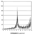
以下、第3実施形態における紙送り量に対する特性の付与について説明する。ここでは、紙送り量の周波数特性を高周波(例えばブルーノイズ特性)とする例を、図42のブロック図と図40のフローチャートを用いて説明する。図42は、第3実施形態における紙送り量を決定するための回路構成であり、図40は、該紙送り量の設定処理を示すフローチャートである。 Hereinafter, the provision of characteristics with respect to the paper feed amount in the third embodiment will be described. Here, an example in which the frequency characteristic of the paper feed amount is set to a high frequency (for example, a blue noise characteristic) will be described with reference to the block diagram of FIG. 42 and the flowchart of FIG. FIG. 42 shows a circuit configuration for determining the paper feed amount in the third embodiment, and FIG. 40 is a flowchart showing the paper feed amount setting process.
ここでは、図41に示すように、縦:1画素×横:入力画像の縦サイズ(Y)の画像メモリ4101を用意し、このメモリ分の画像データ4102に対して誤差拡散処理を行うことによって、2値画像4103を作成する。第3実施形態においては、2値画像4103においてドットがONとなる画素(黒画素)間の距離により、各走査後の紙送り量を示す。
Here, as shown in FIG. 41, by preparing an
まず、図41に示す画像データ4102の画素値を決定する(S401)。具体的には、画像データ4102の平均画素値が、同一記録領域を走査するパス数とノズル長に基づく下式(38)で示される値Iaveとなるように、各画素値を決定する。なお、ここでは1画素を8ビットで表すとする。
First, the pixel value of the
Iave=255/ノズル長/パス数 ・・・(38)
例えば、平均がIave、分散σとなるような一様乱数を発生し、四捨五入を行って得られる整数を、画像データ4102の画素値とする。このとき、分散値σによって紙送り量の特性を制御することが可能である。
Iave = 255 / nozzle length / number of passes (38)
For example, a uniform random number having an average of Iave and variance σ is generated, and an integer obtained by rounding is used as the pixel value of the
次に、以降の処理において使用されるパラメータ△H[],Q[],p,jの値を、それぞれ0に初期化する(S402)。なお、pはパス数を示し、△H[p]は第pパスによる画像形成後の紙送り量を示すパラメータである。また、Q[p]は第pパス後の紙送り量の妥当性を判定するためのパラメータである。ここで紙送り量の妥当性とは、紙送り量がノズル長を超えるか否かによって判定される。またjは、画像データ4102および2値画像4103の画素位置を示すパラメータである。
Next, the values of parameters ΔH [], Q [], p, j used in the subsequent processes are initialized to 0 (S402). Note that p indicates the number of passes, and ΔH [p] is a parameter indicating the paper feed amount after image formation by the p-th pass. Q [p] is a parameter for determining the validity of the paper feed amount after the p-th pass. Here, the validity of the paper feed amount is determined by whether or not the paper feed amount exceeds the nozzle length. J is a parameter indicating the pixel position of the
そして、多値の画像データ4102に対して、誤差拡散処理を行う(S403)。この誤差拡散処理については周知の手法が適用可能であるため、ここでは概要のみの説明にとどめる。すなわち図42において、量子化部4202で量子化閾値4201に基づき、入力データを量子化する。このときに誤差演算部4205で算出される入力データと量子化データの差分を、誤差として誤差拡散部4204で周辺画素に拡散していく。
Then, error diffusion processing is performed on the multi-valued image data 4102 (S403). Since a well-known method can be applied to the error diffusion processing, only an outline is described here. That is, in FIG. 42, the
なお、第3実施形態において誤差拡散処理に用いられる誤差拡散係数は、図43に示すように1つの係数k1(例えば、K1=1)のみを持つものとする。この誤差拡散処理により、図41に示す2値画像4103が得られる。
Note that the error diffusion coefficient used for the error diffusion processing in the third embodiment has only one coefficient k1 (for example, K1 = 1) as shown in FIG. By this error diffusion processing, a
次に、図42に示す紙送り量判定部4206において、誤差拡散処理によって作成された2値画像4103に対し、設定されている紙送り量が妥当であるか否かを判定する。
Next, the paper feed
まず、2値画像4103における画素Out(1,j)の値が、1:ON(4103における黒画素)であるか否かを判定する(S404)。Out(1,j)がONであれば、パス数を設定する。すなわち、pをパス数と比較し(S405)、pがパス数よりも小さければpをインクリメントし(S406)、パス数以上であれば、pをパス数との差分値すなわち0に更新する(S407)。なお、pの値は上述したように、誤差拡散処理前に0に初期化されている。そして、紙送り量判定パラメータQ[p]の値をjに更新する(S408)。なお、Q[p]の値は上述したように、誤差拡散処理前に0で初期化されている。
First, it is determined whether or not the value of the pixel Out (1, j) in the
一方、ステップS404においてOut(1,j)が0:OFF(4103における白画素)である場合には、下式(39)により紙送り量△H[p]を算出する(S409)。 On the other hand, if Out (1, j) is 0: OFF (white pixel in 4103) in step S404, the paper feed amount ΔH [p] is calculated by the following equation (39) (S409).
△H[p]=|注目画素のj座標−Q[p]| ・・・(39)
ここで上述したように、第3実施形態においては、図41に示す2値画像4103における黒画素間の距離により、紙送り量が示される。したがって、式(39)によって算出される△H[p]は、ノズル長以下でなければならないため、△H[p]とノズル長を比較することにより紙送り量の妥当性を判定する(S410)。そして、△H[p]がノズル長以下である場合には、この△H[p]は適切な値であるため、次の処理に移行する(S412,S413)。
ΔH [p] = | j coordinate of the pixel of interest−Q [p] | (39)
As described above, in the third embodiment, the paper feed amount is indicated by the distance between the black pixels in the
一方、△H[p]がノズル長より大きい場合は、この△H[p]は不適切であるとして、注目画素の2値化結果Out(1,j)をONにする(S411)。その後、パス数を設定し(S405〜S407)、紙送り量判定パラメータQ[p]の値をjに更新する(S408)。 On the other hand, if ΔH [p] is larger than the nozzle length, it is determined that ΔH [p] is inappropriate, and the binarization result Out (1, j) of the target pixel is turned ON (S411). Thereafter, the number of passes is set (S405 to S407), and the value of the paper feed amount determination parameter Q [p] is updated to j (S408).
以上説明したステップS402〜S411の処理が、図41に示す画像データ4102の全画素に対して終了したか否かを判定し(S412)、未終了であれば次の画素の処理に移行するために、jをインクリメントする(S413)。
It is determined whether or not the processing in steps S402 to S411 described above has been completed for all the pixels of the
以上説明した図40のフローチャートに示す処理によって、図41に示す2値画像4103が得られる。図44に、この2値画像4103の周波数特性を示す。図44によれば、2値画像4103が高域に偏ったブルーノイズ特性を有していることが確認できる。このように第3実施形態によれば、2値画像4103における黒画素間の距離に相当する紙送りを行うことで、紙送り量にブルーノイズ特性を付与することが可能となる。
The
第3実施形態においては、以上の方法により設定した紙送りを実現するための入力DUTY分割テーブルを作成する。以下、第3実施形態における入力DUTY分割テーブルの作成方法について、図46のフローチャートを用いて説明する。なお、入力DUTY分割テーブルの作成に先立って、図45に示すような、横サイズが入力画像の縦サイズ(1メモリは画像の縦方向の解像度に相当)であり、縦サイズが10(0〜1まで0.1刻みの格子)である領域を確保しておく。以下、この領域をテーブル領域と称し、横軸および縦軸の座標をそれぞれi,jとする。 In the third embodiment, an input DUTY division table for realizing paper feeding set by the above method is created. Hereinafter, a method of creating the input DUTY division table in the third embodiment will be described with reference to the flowchart of FIG. Prior to the creation of the input DUTY division table, as shown in FIG. 45, the horizontal size is the vertical size of the input image (one memory corresponds to the vertical resolution of the image), and the vertical size is 10 (0 to 0). An area which is a grid of 0.1 increments up to 1) is secured. Hereinafter, this area is referred to as a table area, and the coordinates of the horizontal axis and the vertical axis are i and j, respectively.
まず、上述した方法により、紙送り量を示す2値画像4103を作成する(S4601)。
First, a
図45においては、点線で示す位置hm(m=1,2,3,・・・)が紙送りが実行される位置(以下、紙送り位置)であり、すなわち図45に示す紙送り位置hmは、図41に示した2値画像4103の黒画素位置に対応している。
In FIG. 45, a position hm (m = 1, 2, 3,...) Indicated by a dotted line is a position (hereinafter referred to as a paper feed position) where paper feed is executed, that is, a paper feed position hm shown in FIG. Corresponds to the black pixel position of the
次に、同一記録領域を形成するパス数を決定する(S4602)。パス数は、印字モードや記録媒体に応じて決定されることが多い。第3実施形態では、同一記録領域を4パス印字で形成していく場合を例として説明する。 Next, the number of passes for forming the same recording area is determined (S4602). The number of passes is often determined according to the print mode and the recording medium. In the third embodiment, a case where the same recording area is formed by four-pass printing will be described as an example.
4パス印字を行うためには、まず、図45に示すテーブル領域内を横方向に4つの領域に分割するが、この分割をステップS4603〜S4605において行う。 In order to perform four-pass printing, first, the table area shown in FIG. 45 is divided into four areas in the horizontal direction, and this division is performed in steps S4603 to S4605.
まず、第1領域を設定するための頂点をn個設定する(S4603)。この頂点の数について特に制限はなく、例えば、分割率を滑らかに変化させたい場合には点の数を増やすとよい。また、第1領域を設定するための頂点an(i_an,j_an)の値の範囲は、例えば4パス印字であれば、各パス間で記録データの差が大きくならないように、j座標幅の平均が所定値(例えば0.25)となるように設定するなどの工夫が考えられる。 First, n vertices for setting the first region are set (S4603). There is no particular limitation on the number of vertices. For example, when it is desired to smoothly change the division ratio, the number of points may be increased. Further, the range of the value of the vertex an (i_an, j_an) for setting the first area is, for example, the average of the j-coordinate widths so that the difference in the recording data does not increase between the passes if printing is performed with 4 passes. It is conceivable to devise such that the value is set to a predetermined value (for example, 0.25).
ここで図47に、第1領域を設定するための頂点a1〜a7の設定例を示す。このとき、頂点anのi座標は下式を満たす。なお、nは第1領域を設定するための頂点数を示し、頂点a1のi座標は0とする。 FIG. 47 shows an example of setting the vertices a1 to a7 for setting the first region. At this time, the i coordinate of the vertex an satisfies the following expression. Note that n indicates the number of vertices for setting the first region, and the i coordinate of the vertex a1 is 0.
i_a1<i_a2<…<i_an ・・・(40)
すなわち、i座標については式(16)を満たしつつ、j座標値を適宜設定する。
i_a1 <i_a2 <... <i_an (40)
That is, for the i coordinate, the j coordinate value is appropriately set while satisfying the equation (16).
次に、第2領域の頂点をn'個設定する(S4604)。なお、この頂点の数についても特に制限はなく、例えば、分割率を滑らかに変化させたい場合は点の数を増やすとよい。 Next, n ′ vertices in the second area are set (S4604). The number of vertices is not particularly limited. For example, when the division ratio is to be changed smoothly, the number of points may be increased.
第2領域の頂点を設定するにあたり、まず、その際に参照される値rn'(i_rn',j_rn')を設定する。この値rn'(i_rn',j_rn')は、i座標が第2領域の頂点のi座標を示し、j座標は第2領域の頂点から第1領域への距離を示し、以下のように設定される。まず、i座標について、下式を満たす。 In setting the vertices of the second region, first, values rn ′ (i_rn ′, j_rn ′) to be referred to at that time are set. This value rn ′ (i_rn ′, j_rn ′) is the i coordinate indicating the i coordinate of the vertex of the second region, the j coordinate indicating the distance from the vertex of the second region to the first region, and is set as follows: Is done. First, the following formula is satisfied for the i coordinate.
i_r1<i_r2<…<i_rn' ・・・(41)
そしてrn'におけるj座標の範囲については、例えば4パス印字であれば、各パス間で記録データの差が大きくならないように、j座標幅の平均が所定値(例えば0.25)となるように設定するなどの工夫が考えられる。
i_r1 <i_r2 <... <i_rn '(41)
As for the range of the j coordinate at rn ′, for example, in the case of 4-pass printing, the average of the j-coordinate width is set to a predetermined value (for example, 0.25) so that the difference in recording data between the passes does not increase. It is possible to devise such as setting to.
次に、第2領域を設定するための頂点bn'(i_bn',j_bn')を、上記rn'を用いて以下の式(42),(43)により算出する。 Next, a vertex bn ′ (i_bn ′, j_bn ′) for setting the second region is calculated by the following equations (42) and (43) using the above rn ′.
i_bn'=i_rn' ・・・(42)
j_bn'=j_rn'+j_a((n'-1)・n') ・・・(43)
なお、式(42),(43)による頂点bn'の算出については、上述した第1実施形態において図18を用いて説明したとおりであるため、ここでは詳細な説明を省略する。図47に、第2領域を設定するための頂点b1〜b5の設定例を示す。
i_bn '= i_rn' (42)
j_bn ′ = j_rn ′ + j_a ((n′−1) · n ′) (43)
Note that the calculation of the vertex bn ′ by the equations (42) and (43) is as described with reference to FIG. 18 in the first embodiment described above, and thus detailed description thereof is omitted here. FIG. 47 shows an example of setting the vertices b1 to b5 for setting the second region.
そして、同様に第3領域用の頂点cnを設定する(S4605)。図47に、第3領域を設定するための頂点c1〜c7の設定例を示す。またこのとき、残りの領域が第4領域として設定される。 Similarly, the vertex cn for the third region is set (S4605). FIG. 47 shows an example of setting the vertices c1 to c7 for setting the third region. At this time, the remaining area is set as the fourth area.
以上のように領域の横4分割が終了すると、次に、各領域を何走査目で記録するかを決定するために、各領域の縦方向の分割点を設定する(S4606)。第3実施形態における分割点は、紙送り位置hm上に設定される。 When the horizontal division of the area is completed as described above, next, the division point in the vertical direction of each area is set in order to determine at which scan each area is recorded (S4606). The division points in the third embodiment are set on the paper feed position hm.
まず第1領域については、紙送り位置h(4n+1)で分割する。なお、ここでのnは、n=1,2,3・・・の変数である。 First, the first area is divided at the paper feed position h (4n + 1). Here, n is a variable of n = 1, 2, 3,.
同様に、第2,第3,第4領域については、それぞれ紙送り位置h(4n+2),h(4n+3),h(4n+4)により、i軸方向に複数の領域に分割する。 Similarly, the second, third, and fourth areas are divided into a plurality of areas in the i-axis direction by paper feed positions h (4n + 2), h (4n + 3), and h (4n + 4), respectively. To do.
以上のような領域分割により設定された複数の多角形領域に対して、走査番号を割り当てる(S4607)。ここでの走査番号の振り方の規則は以下の通りである。まず、第1領域最も左についての走査番号を1とし、次に、その上にある多角形領域(第2領域の最も左)の走査番号を2とする。同様な規則で走査番号を順次付していくことにより、各領域には以下のような走査番号が付される。 Scan numbers are assigned to a plurality of polygonal areas set by area division as described above (S4607). The rules for assigning scan numbers here are as follows. First, the scan number for the leftmost first region is set to 1, and then the scan number of the polygonal region (leftmost of the second region) thereabove is set to 2. By sequentially assigning scan numbers according to the same rule, the following scan numbers are assigned to each region.
第1領域:走査番号(4n+1)
第2領域:走査番号(4n+2)
第3領域:走査番号(4n+3)
第4領域:走査番号(4n+4)
以上の方法により、図48に示すような入力DUTY分割テーブルが作成される。
First area: scanning number (4n + 1)
Second area: scanning number (4n + 2)
Third area: scanning number (4n + 3)
Fourth area: scanning number (4n + 4)
By the above method, an input DUTY division table as shown in FIG. 48 is created.
第3実施形態における記録データ設定用LUT106は、上述した方法により作成された入力DUTY分割テーブルに基づき、第1実施形態と同様に、各走査番号kごとに算出された以下の3項目の値が格納される。すなわち、1)色分解データ切り出し位置Ycut(k)、2)各ノズルに対する入力データの分割率、そして、3)走査後の紙送り量LF(k)である。
The print
続いて、このように設定された記録データ設定用LUT106を用いて、記録データ設定部105で記録データを設定し、記録データ格納メモリ107に格納する。なお、その後のハーフトーン処理については、上述した第1実施形態と同様であるため、説明を省略する。
Subsequently, using the recording
以上説明したように第3実施形態によれば、上述した第1実施形態に加えて、各走査後の記憶媒体の搬送量に対して、任意の特性を付与して設定することができる。 As described above, according to the third embodiment, in addition to the first embodiment described above, an arbitrary characteristic can be set for the transport amount of the storage medium after each scan.
<第4実施形態>
以下、本発明に係る第4実施形態について説明する。上述した第2実施形態においては、マルチパス記録方式におけるパス数を任意に設定する例を示したが、第4実施形態では、特に画像の後端部分についてパス数を増やした印字を行う例を示す。なお、第4実施形態における画像形成装置の構成は、上述した第1実施形態と同様であるため、説明を省略する。
<Fourth embodiment>
The fourth embodiment according to the present invention will be described below. In the above-described second embodiment, an example in which the number of passes in the multi-pass printing method is arbitrarily set has been described. In the fourth embodiment, in particular, an example in which printing is performed with an increased number of passes for the rear end portion of an image. Show. Note that the configuration of the image forming apparatus according to the fourth embodiment is the same as that of the first embodiment described above, and a description thereof will be omitted.
第4実施形態におけるパス数の制御も、上述した第2実施形態と同様に入力DUTY分割テーブルに基づいて行われる。以下、第4実施形態における入力DUTY分割テーブルの作成方法について、図49のフローチャートを用いて説明する。なおここでは、画像の後端以外の領域(通常領域)では4パス印字による通常処理を行い、後端領域では8パス印字による後端処理を行うように、入力DUTY分割テーブルを作成する例を示す。 The number of passes in the fourth embodiment is also controlled based on the input DUTY division table as in the second embodiment described above. Hereinafter, a method of creating the input DUTY division table in the fourth embodiment will be described with reference to the flowchart of FIG. In this example, the input DUTY division table is created so that normal processing by 4-pass printing is performed in a region other than the rear end (normal region) of the image, and rear-end processing by 8-pass printing is performed in the rear end region. Show.
まずステップS4901において、形成画像における後端領域を決定する。この後端領域の決定方法としては例えば、入力データのサイズによらず、入力画像の下端の数%の領域を後端領域とする方法や、センサにより紙の後端を検出し、ノズル長と後端領域でのパス数に応じて設定してもよい。ここで、画像のYアドレスにおいて、決定した後端領域の開始位置をSとする。 First, in step S4901, the rear end region in the formed image is determined. As a method for determining the rear end area, for example, a method in which a few percent of the lower end of the input image is used as the rear end area regardless of the size of the input data, or the rear end area of the paper is detected by a sensor, and the nozzle length is determined. It may be set according to the number of passes in the rear end region. Here, it is assumed that the start position of the determined rear end region is S in the Y address of the image.
そして、後端処理を行わない通常領域に対し、上述した第1実施形態に示した方法によって4パス用の入力DUTY分割テーブルを作成する(S4902)。 Then, an input DUTY division table for four passes is created for the normal area where the rear end processing is not performed by the method described in the first embodiment (S4902).
次に、後端処理を行う領域に対して、以下のように8パス用の入力DUTY分割テーブルを作成する(S4903)。 Next, an input DUTY division table for 8 passes is created for the area where the rear end processing is performed as follows (S4903).
ここで図50に、以上のように作成された入力DUTY分割テーブル例を示す。同図によれば、画像のYアドレスiが後端開始位置Sよりも小さい領域(i<S)がすなわち通常領域であり、4パスによる分割がなされている。一方、i≧Sの領域については、横方向に8分割されている。この分割方法については、上述した第2実施形態で示した方法において、最小パス数を4、最大パス数を8として適用すればよい。すなわち図50に示すように、第4,第5,第6,第7領域はi≧Sの後端処理においてのみ必要となる。この第4,第5,第6,第7領域用のそれぞれの頂点dn(i_dn,j_dn),en(i_en,j_en),fn(i_fn,j_fn),gn(i_gn,j_gn)については、以下の式(44),(45)を満たすように設定されている。 Here, FIG. 50 shows an example of the input DUTY division table created as described above. According to the figure, an area where the Y address i of the image is smaller than the rear end start position S (i <S), that is, a normal area, is divided by four passes. On the other hand, the region of i ≧ S is divided into eight in the horizontal direction. As for this division method, the minimum number of paths may be 4 and the maximum number of paths may be 8 in the method described in the second embodiment. That is, as shown in FIG. 50, the fourth, fifth, sixth, and seventh regions are required only in the rear end process of i ≧ S. The vertices dn (i_dn, j_dn), en (i_en, j_en), fn (i_fn, j_fn), gn (i_gn, j_gn) for the fourth, fifth, sixth and seventh regions are as follows. It is set to satisfy the expressions (44) and (45).
i_d1=i_e1=i_f1=i_g1=S ・・・(44)
j_d1=j_e1=j_f1=j_g1=1 ・・・(45)
なお図50に示す入力DUTY分割テーブルにおいては、後端領域内の第1〜第3領域については、通常領域において分割した領域との連続性が保たれるように設定している。しかしながら第4実施形態における入力DUTY分割テーブルの作成方法はこれに限らず、i≧Sの後端領域内において、上述した第1実施形態に示した方法により、横方向への8分割を行ってもよい。
i_d1 = i_e1 = i_f1 = i_g1 = S (44)
j_d1 = j_e1 = j_f1 = j_g1 = 1 (45)
In the input DUTY division table shown in FIG. 50, the first to third areas in the rear end area are set so as to maintain continuity with the areas divided in the normal area. However, the method of creating the input DUTY division table in the fourth embodiment is not limited to this, and the eight divisions in the horizontal direction are performed in the rear end region of i ≧ S by the method described in the first embodiment. Also good.
第4実施形態においては、図50に示すような入力DUTY分割テーブルを作成することにより、通常領域では4パス、後端領域では8パスによる印字が実現される。 In the fourth embodiment, by creating an input DUTY division table as shown in FIG. 50, printing is realized with 4 passes in the normal area and 8 passes in the rear end area.
第4実施形態における記録データ設定用LUT106は、上述した方法により作成された入力DUTY分割テーブルに基づき、上述した第2実施形態と同様に、各走査番号kごとに以下の項目の値が格納される。すなわち、1)色分解データ切り出し位置Ycut(k)、2)各ノズルに対する入力データの分割率、3)走査後の紙送り量LF(k)、そして、4)隣接領域番号L、が格納される。
The recording
続いて、このように設定された記録データ設定用LUT106を用いて、記録データ設定部105で記録データを設定し、記録データ格納メモリ107に格納する。
Subsequently, using the recording
その後のハーフトーン処理については、上述した第1実施形態と同様に誤差拡散処理により行う。第4実施形態の誤差拡散処理においては、誤差を拡散して累積するためにはハーフトーン処理部108における累積誤差ラインバッファを最大パス数組分(この例では8組)確保する必要がある。そして、使用する累積誤差ラインバッファを、記録データ設定用LUT106の「隣接領域番号L」の値に基づいて切り替える。その他の処理については第1実施形態と同様であるため、説明を省略する。
Subsequent halftone processing is performed by error diffusion processing as in the first embodiment described above. In the error diffusion processing according to the fourth embodiment, in order to diffuse and accumulate errors, it is necessary to secure the maximum number of accumulated error line buffers in the halftone processing unit 108 (eight in this example). Then, the cumulative error line buffer to be used is switched based on the value of “adjacent area number L” of the recording
以上説明したように第4実施形態によれば、特に画像の後端部分においてパス数を増やすように設定することが可能となる。これにより、搬送時のずれが特に発生しやすい後端部において、紙送りずれによる画質劣化のない画像を形成することができる。 As described above, according to the fourth embodiment, it is possible to set so as to increase the number of passes, particularly in the rear end portion of the image. As a result, it is possible to form an image free from image quality deterioration due to paper feeding deviation at the rear end portion where deviation during conveyance is particularly likely to occur.
<他の実施形態>
上述した各実施形態では、所定方向に配列された複数のノズルを有する記録ヘッドをノズルの配列方向と交差する方向に記録媒体上で走査させて、記録媒体にインクを吐出することで画像を形成するインクジェット記録方式を用いた画像処理装置を説明した。しかしながら本発明は、インクジェット方式以外の他の方式に従って記録を行う記録装置(例えば熱転写方式や電子写真方式)に対しても適用できる。この場合、インク滴を吐出するノズルはドットを記録する記録素子やレーザー発光素子に対応することとなる。
<Other embodiments>
In each of the above-described embodiments, an image is formed by causing a recording head having a plurality of nozzles arranged in a predetermined direction to scan on the recording medium in a direction crossing the nozzle arrangement direction and ejecting ink onto the recording medium. An image processing apparatus using an inkjet recording system has been described. However, the present invention can also be applied to a recording apparatus (for example, a thermal transfer method or an electrophotographic method) that performs recording according to a method other than the ink jet method. In this case, the nozzle for ejecting ink droplets corresponds to a recording element for recording dots or a laser light emitting element.
また本発明は例えば、記録媒体の記録幅に対応する長さの記録ヘッドを有し、記録ヘッドに対して記録媒体を移動させて記録を行う、いわゆるフルライン型の記録装置などにも適用できる。 The present invention can also be applied to, for example, a so-called full-line type recording apparatus that has a recording head having a length corresponding to the recording width of the recording medium and performs recording by moving the recording medium relative to the recording head. .
本発明は例えば、システム、装置、方法、プログラム若しくは記憶媒体(記録媒体)等としての実施態様をとることが可能である。具体的には、複数の機器(例えば、ホストコンピュータ、インタフェース機器、撮像装置、webアプリケーション等)から構成されるシステムに適用しても良いし、また、一つの機器からなる装置に適用しても良い。 The present invention can take the form of, for example, a system, apparatus, method, program, or storage medium (recording medium). Specifically, the present invention may be applied to a system composed of a plurality of devices (for example, a host computer, an interface device, an imaging device, a web application, etc.), or may be applied to a device composed of a single device. good.
尚本発明は、前述した実施形態の機能を実現するソフトウェアのプログラムを、システムあるいは装置に直接あるいは遠隔から供給し、そのシステムあるいは装置のコンピュータが該供給されたプログラムコードを読み出して実行することによっても達成される。なお、この場合のプログラムとは、実施形態において図に示したフローチャートに対応したプログラムである。 In the present invention, a software program for realizing the functions of the above-described embodiments is supplied directly or remotely to a system or apparatus, and the computer of the system or apparatus reads and executes the supplied program code. Is also achieved. The program in this case is a program corresponding to the flowchart shown in the drawing in the embodiment.
従って、本発明の機能処理をコンピュータで実現するために、該コンピュータにインストールされるプログラムコード自体も本発明を実現するものである。つまり、本発明は、本発明の機能処理を実現するためのコンピュータプログラム自体も含まれる。 Accordingly, since the functions of the present invention are implemented by computer, the program code installed in the computer also implements the present invention. In other words, the present invention includes a computer program itself for realizing the functional processing of the present invention.
その場合、プログラムの機能を有していれば、オブジェクトコード、インタプリタにより実行されるプログラム、OSに供給するスクリプトデータ等の形態であっても良い。 In this case, as long as it has a program function, it may be in the form of object code, a program executed by an interpreter, script data supplied to the OS, or the like.
プログラムを供給するための記録媒体としては、以下に示す媒体がある。例えば、フロッピー(登録商標)ディスク、ハードディスク、光ディスク、光磁気ディスク、MO、CD-ROM、CD-R、CD-RW、磁気テープ、不揮発性のメモリカード、ROM、DVD(DVD-ROM,DVD-R)などである。 Recording media for supplying the program include the following media. For example, floppy disk, hard disk, optical disk, magneto-optical disk, MO, CD-ROM, CD-R, CD-RW, magnetic tape, nonvolatile memory card, ROM, DVD (DVD-ROM, DVD- R).
プログラムの供給方法としては、以下に示す方法も可能である。すなわち、クライアントコンピュータのブラウザからインターネットのホームページに接続し、そこから本発明のコンピュータプログラムそのもの(又は圧縮され自動インストール機能を含むファイル)をハードディスク等の記録媒体にダウンロードする。また、本発明のプログラムを構成するプログラムコードを複数のファイルに分割し、それぞれのファイルを異なるホームページからダウンロードすることによっても実現可能である。つまり、本発明の機能処理をコンピュータで実現するためのプログラムファイルを複数のユーザに対してダウンロードさせるWWWサーバも、本発明に含まれるものである。 As a program supply method, the following method is also possible. That is, the browser of the client computer is connected to a home page on the Internet, and the computer program itself (or a compressed file including an automatic installation function) is downloaded from the browser to a recording medium such as a hard disk. It can also be realized by dividing the program code constituting the program of the present invention into a plurality of files and downloading each file from a different homepage. That is, a WWW server that allows a plurality of users to download a program file for realizing the functional processing of the present invention on a computer is also included in the present invention.
また、本発明のプログラムを暗号化してCD-ROM等の記憶媒体に格納してユーザに配布し、所定の条件をクリアしたユーザに対し、インターネットを介してホームページから暗号化を解く鍵情報をダウンロードさせることも可能である。すなわち該ユーザは、その鍵情報を使用することによって暗号化されたプログラムを実行し、コンピュータにインストールさせることができる。 In addition, the program of the present invention is encrypted, stored in a storage medium such as a CD-ROM, distributed to users, and key information for decryption is downloaded from a homepage via the Internet to users who have cleared predetermined conditions. It is also possible to make it. That is, the user can execute the encrypted program by using the key information and install it on the computer.
また、コンピュータが、読み出したプログラムを実行することによって、前述した実施形態の機能が実現される。さらに、そのプログラムの指示に基づき、コンピュータ上で稼動しているOSなどが、実際の処理の一部または全部を行い、その処理によっても前述した実施形態の機能が実現され得る。 Further, the functions of the above-described embodiments are realized by the computer executing the read program. Furthermore, based on the instructions of the program, an OS or the like running on the computer performs part or all of the actual processing, and the functions of the above-described embodiments can also be realized by the processing.
さらに、記録媒体から読み出されたプログラムが、コンピュータに挿入された機能拡張ボードやコンピュータに接続された機能拡張ユニットに備わるメモリに書き込まれた後、実行されることによっても、前述した実施形態の機能が実現される。すなわち、該プログラムの指示に基づき、その機能拡張ボードや機能拡張ユニットに備わるCPUなどが実際の処理の一部または全部を行うことが可能である。 Further, the program read from the recording medium is written in a memory provided in a function expansion board inserted into the computer or a function expansion unit connected to the computer, and then executed, so that the program of the above-described embodiment can be obtained. Function is realized. That is, based on the instructions of the program, the CPU provided in the function expansion board or function expansion unit can perform part or all of the actual processing.
Claims (15)
画像データを入力する画像データ入力手段と、
前記記録ヘッドの主走査ごとに、前記記録素子ごとの記録量分割率を設定したテーブルを保持するテーブル保持手段と、
前記画像データに応じて、前記記録ヘッドの主走査ごとに、前記記録素子ごとの記録量を、前記テーブルに基づいて設定する走査内記録量設定手段と、
前記走査内記録量設定手段で設定された記録量に対し、N値化処理(Nは2以上の整数)を施して形成対象となるドットパターンを作成するN値化手段と、を有し、
前記テーブルは、前記記録媒体上の同一領域を形成するための主走査の回数と、主走査ごとに使用する記録素子数に基づいて作成されていることを特徴とする画像形成装置。 An image forming apparatus that forms an image by scanning a recording head including a plurality of recording elements on a recording medium,
Image data input means for inputting image data;
A table holding means for holding a table in which a recording amount division ratio for each recording element is set for each main scanning of the recording head;
Intra-scan recording amount setting means for setting a recording amount for each recording element based on the table for each main scan of the recording head according to the image data;
N-value conversion means for creating a dot pattern to be formed by performing N-value conversion processing (N is an integer of 2 or more) for the recording amount set by the in-scan recording amount setting means,
The image forming apparatus, wherein the table is created based on the number of times of main scanning for forming the same area on the recording medium and the number of recording elements used for each main scanning.
画像データ入力手段が、画像データを入力する画像入力ステップと、
走査内記録量設定手段が、前記画像データに応じて、前記記録ヘッドの主走査ごとに、前記記録素子ごとの記録量を、前記主走査ごとに前記記録素子ごとの記録量分割率を設定したテーブルに基づいて設定する走査内記録量設定ステップと、
N値化手段が、前記走査内記録量設定ステップにおいて設定された記録量に対し、N値化処理(Nは2以上の整数)を施して形成対象となるドットパターンを作成するN値化ステップと、を有し、
前記テーブルは、前記記録媒体上の同一領域を形成するための主走査の回数と、主走査ごとに使用する記録素子数に基づいて作成されていることを特徴とする画像形成装置の制御方法。 A control method of an image forming apparatus for forming an image by scanning a recording head including a plurality of recording elements on a recording medium,
An image input step in which the image data input means inputs the image data;
The in-scan recording amount setting means sets the recording amount for each recording element for each main scanning of the recording head and the recording amount division ratio for each recording element for each main scanning according to the image data. An intra-scan recording amount setting step set based on the table;
An N-value conversion step for generating a dot pattern to be formed by applying an N-value conversion process (N is an integer of 2 or more) to the recording amount set in the intra-scan recording amount setting step. And having
The control method of an image forming apparatus, wherein the table is created based on the number of main scans for forming the same area on the recording medium and the number of recording elements used for each main scan.
画像データを入力する画像データ入力手段と、
前記記録ヘッドの主走査ごとに、前記記録素子ごとの記録量分割率を設定したテーブルを保持するテーブル保持手段と、
前記画像データに応じて、前記記録ヘッドの主走査ごとに、前記記録素子ごとの記録量を、前記テーブルに基づいて設定する走査内記録量設定手段と、
前記走査内記録量設定手段で設定された記録量に対し、N値化処理(Nは2以上の整数)を施して形成対象となるドットパターンを作成するN値化手段と、を有し、
前記テーブルは、前記記録媒体上の同一領域を形成するための主走査の回数と、主走査ごとに使用する記録素子数に基づいて作成されていることを特徴とする画像処理装置。 An image processing apparatus that outputs a dot pattern to an image forming apparatus that forms an image by scanning a recording head including a plurality of recording elements on a recording medium,
Image data input means for inputting image data;
A table holding means for holding a table in which a recording amount division ratio for each recording element is set for each main scanning of the recording head;
Intra-scan recording amount setting means for setting a recording amount for each recording element based on the table for each main scan of the recording head according to the image data;
N-value conversion means for creating a dot pattern to be formed by performing N-value conversion processing (N is an integer of 2 or more) for the recording amount set by the in-scan recording amount setting means,
The image processing apparatus, wherein the table is created based on the number of main scans for forming the same region on the recording medium and the number of recording elements used for each main scan.
画像データ入力手段が、画像データを入力する画像入力ステップと、
走査内記録量設定手段が、前記画像データに応じて、前記記録ヘッドの主走査ごとに、前記記録素子ごとの記録量を、前記主走査ごとに前記記録素子ごとの記録量分割率を設定したテーブルに基づいて設定する走査内記録量設定ステップと、
N値化手段が、前記走査内記録量設定ステップにおいて設定された記録量に対し、N値化処理(Nは2以上の整数)を施して形成対象となるドットパターンを作成するN値化ステップと、を有し、
前記テーブルは、前記記録媒体上の同一領域を形成するための主走査の回数と、主走査ごとに使用する記録素子数に基づいて作成されていることを特徴とする画像処理装置の制御方法。 A control method for an image processing apparatus that outputs a dot pattern to an image forming apparatus that forms an image by scanning a recording head including a plurality of recording elements on a recording medium,
An image input step in which the image data input means inputs the image data;
The in-scan recording amount setting means sets the recording amount for each recording element for each main scanning of the recording head and the recording amount division ratio for each recording element for each main scanning according to the image data. An intra-scan recording amount setting step set based on the table;
An N-value conversion step for generating a dot pattern to be formed by applying an N-value conversion process (N is an integer of 2 or more) to the recording amount set in the intra-scan recording amount setting step. And having
The method of controlling an image processing apparatus, wherein the table is created based on the number of main scans for forming the same area on the recording medium and the number of recording elements used for each main scan.
前記記録媒体上の同一領域を形成するための主走査数を設定する主走査数設定ステップと、
横軸が前記画像データにおける前記記録ヘッドの副走査方向の位置を示し、縦軸が入力データ分割率を示すテーブル領域を、前記画像データにおける副走査方向の位置に対して設定された分割率に応じて、前記主走査数設定ステップにおいて設定された主走査数に応じた数の領域に、前記横軸の方向に分割する横方向分割ステップと、
前記横方向分割ステップで分割された領域のそれぞれをさらに、主走査ごとに使用する記録素子の数に応じた領域に、前記縦軸の方向に分割する縦方向分割ステップと、
前記横方向分割ステップおよび前記縦方向分割ステップにより分割された領域のそれぞれに対し、主走査順を示す走査番号を設定する走査番号設定ステップと、
を有することを特徴とするテーブル作成方法。 In an image forming apparatus that forms an image by scanning a recording head including a plurality of recording elements on a recording medium, for each main scanning of the recording head, for each recording element, according to input image data A method for creating a table to be referred to for setting a recording amount,
A main scanning number setting step for setting a main scanning number for forming the same region on the recording medium;
The horizontal axis indicates the position of the recording head in the sub-scanning direction in the image data, and the vertical axis indicates the input data division ratio in the division ratio set with respect to the position in the sub-scanning direction in the image data. In response, a horizontal direction dividing step for dividing in the direction of the horizontal axis into a number of regions corresponding to the number of main scans set in the main scanning number setting step;
Each of the areas divided in the horizontal direction dividing step is further divided in the direction of the vertical axis into areas corresponding to the number of printing elements used for each main scan,
A scanning number setting step for setting a scanning number indicating a main scanning order for each of the regions divided by the horizontal direction dividing step and the vertical direction dividing step;
A table creation method characterized by comprising:
Priority Applications (2)
| Application Number | Priority Date | Filing Date | Title |
|---|---|---|---|
| JP2007029712A JP2008194854A (en) | 2007-02-08 | 2007-02-08 | Image forming apparatus, image processing apparatus, and its controlling method |
| US12/025,409 US8253974B2 (en) | 2007-02-08 | 2008-02-04 | Image forming apparatus, image processing apparatus, and control method therefor |
Applications Claiming Priority (1)
| Application Number | Priority Date | Filing Date | Title |
|---|---|---|---|
| JP2007029712A JP2008194854A (en) | 2007-02-08 | 2007-02-08 | Image forming apparatus, image processing apparatus, and its controlling method |
Publications (2)
| Publication Number | Publication Date |
|---|---|
| JP2008194854A true JP2008194854A (en) | 2008-08-28 |
| JP2008194854A5 JP2008194854A5 (en) | 2010-03-25 |
Family
ID=39685538
Family Applications (1)
| Application Number | Title | Priority Date | Filing Date |
|---|---|---|---|
| JP2007029712A Pending JP2008194854A (en) | 2007-02-08 | 2007-02-08 | Image forming apparatus, image processing apparatus, and its controlling method |
Country Status (2)
| Country | Link |
|---|---|
| US (1) | US8253974B2 (en) |
| JP (1) | JP2008194854A (en) |
Cited By (3)
| Publication number | Priority date | Publication date | Assignee | Title |
|---|---|---|---|---|
| JP2010162770A (en) * | 2009-01-15 | 2010-07-29 | Seiko Epson Corp | Printing apparatus, dither mask, and printing method |
| JP2012144052A (en) * | 2012-05-08 | 2012-08-02 | Canon Inc | Image processing device and image processing method |
| JP2017056682A (en) * | 2015-09-18 | 2017-03-23 | 富士フイルム株式会社 | Dither mask generation method and device, and program |
Families Citing this family (8)
| Publication number | Priority date | Publication date | Assignee | Title |
|---|---|---|---|---|
| JP5147251B2 (en) * | 2007-02-01 | 2013-02-20 | キヤノン株式会社 | Image processing apparatus and image processing apparatus control method |
| JP4777268B2 (en) * | 2007-02-01 | 2011-09-21 | キヤノン株式会社 | Image forming apparatus and image processing apparatus control method |
| JP5290614B2 (en) * | 2008-04-25 | 2013-09-18 | キヤノン株式会社 | Image forming apparatus, print data generation method, and computer program |
| US8134750B2 (en) * | 2009-03-13 | 2012-03-13 | Ricoh Production Print Solutions LLC | Printing with alternative halftone patterns in ink jet printing to reduce ink penetration |
| JP2011062884A (en) * | 2009-09-16 | 2011-03-31 | Konica Minolta Business Technologies Inc | Image processor |
| JP5433645B2 (en) * | 2011-07-22 | 2014-03-05 | 富士フイルム株式会社 | Liquid discharge amount control apparatus and method, program, and ink jet apparatus |
| JP6029343B2 (en) * | 2012-06-19 | 2016-11-24 | キヤノン株式会社 | Image processing apparatus and control method thereof |
| CN110674152B (en) * | 2019-09-24 | 2023-06-23 | 京东科技控股股份有限公司 | Data synchronization method and device, storage medium and electronic equipment |
Citations (3)
| Publication number | Priority date | Publication date | Assignee | Title |
|---|---|---|---|---|
| JP2004230863A (en) * | 2003-02-03 | 2004-08-19 | Canon Inc | Ink jet recording apparatus |
| JP2005007613A (en) * | 2003-06-16 | 2005-01-13 | Canon Inc | Inkjet recording device and inkjet recording method |
| JP2005231060A (en) * | 2004-02-17 | 2005-09-02 | Fuji Xerox Co Ltd | Image processor and inkjet recording apparatus |
Family Cites Families (21)
| Publication number | Priority date | Publication date | Assignee | Title |
|---|---|---|---|---|
| ATE225540T1 (en) * | 1993-05-27 | 2002-10-15 | Canon Kk | METHOD AND APPARATUS FOR INKJET RECORDING |
| JPH0752465A (en) | 1993-06-30 | 1995-02-28 | Canon Inc | Ink jet recording device |
| JP3408089B2 (en) * | 1996-11-27 | 2003-05-19 | キヤノン株式会社 | Ink jet recording apparatus and method, and data control apparatus |
| US6406113B1 (en) * | 1997-05-07 | 2002-06-18 | Canon Kabushiki Kaisha | Control method for ink jet recording apparatus and ink jet recording apparatus |
| JP3818557B2 (en) | 1998-03-03 | 2006-09-06 | 株式会社リコー | Inkjet recording device |
| DE60035549T2 (en) * | 1999-06-07 | 2008-04-17 | Canon K.K. | Imaging device and method |
| JP4164224B2 (en) | 1999-08-24 | 2008-10-15 | キヤノン株式会社 | Inkjet recording apparatus and inkjet recording method |
| DE60035929T2 (en) * | 1999-08-24 | 2008-05-15 | Canon K.K. | Ink jet printing apparatus and ink jet printing method |
| JP4497597B2 (en) * | 1999-10-05 | 2010-07-07 | キヤノン株式会社 | Image processing apparatus and image processing method |
| JP4931165B2 (en) * | 2000-08-31 | 2012-05-16 | キヤノン株式会社 | Image recording apparatus and image processing apparatus |
| US6871934B2 (en) * | 2002-03-28 | 2005-03-29 | Canon Kabushiki Kaisha | Ink jet print head and ink jet printing apparatus |
| WO2004103709A1 (en) * | 2003-05-22 | 2004-12-02 | Seiko Epson Corporation | Liquid jetting device and liquid jetting method |
| JP4328580B2 (en) * | 2003-08-11 | 2009-09-09 | キヤノン株式会社 | Ink jet recording method, program for carrying out the method, and ink jet recording apparatus |
| JP4470501B2 (en) * | 2004-01-22 | 2010-06-02 | セイコーエプソン株式会社 | Calibration of ink discharge for printer |
| JP4551719B2 (en) * | 2004-08-18 | 2010-09-29 | キヤノン株式会社 | Ink jet recording apparatus and control method of ink jet recording apparatus |
| US7290855B2 (en) * | 2004-08-18 | 2007-11-06 | Canon Kabushiki Kaisha | Printing apparatus and printing method |
| JP2006115431A (en) * | 2004-10-18 | 2006-04-27 | Sony Corp | Intermediate tone processor, printer, information processing apparatus, intermediate tone processing method and program |
| US20060087527A1 (en) * | 2004-10-27 | 2006-04-27 | De Pena Alejandro M | Method for preparing a print mask |
| US7706023B2 (en) * | 2005-06-30 | 2010-04-27 | Canon Kabushiki Kaisha | Data processing method, printing apparatus, host apparatus, and printing system |
| JP4777268B2 (en) * | 2007-02-01 | 2011-09-21 | キヤノン株式会社 | Image forming apparatus and image processing apparatus control method |
| JP5147251B2 (en) | 2007-02-01 | 2013-02-20 | キヤノン株式会社 | Image processing apparatus and image processing apparatus control method |
-
2007
- 2007-02-08 JP JP2007029712A patent/JP2008194854A/en active Pending
-
2008
- 2008-02-04 US US12/025,409 patent/US8253974B2/en not_active Expired - Fee Related
Patent Citations (3)
| Publication number | Priority date | Publication date | Assignee | Title |
|---|---|---|---|---|
| JP2004230863A (en) * | 2003-02-03 | 2004-08-19 | Canon Inc | Ink jet recording apparatus |
| JP2005007613A (en) * | 2003-06-16 | 2005-01-13 | Canon Inc | Inkjet recording device and inkjet recording method |
| JP2005231060A (en) * | 2004-02-17 | 2005-09-02 | Fuji Xerox Co Ltd | Image processor and inkjet recording apparatus |
Cited By (4)
| Publication number | Priority date | Publication date | Assignee | Title |
|---|---|---|---|---|
| JP2010162770A (en) * | 2009-01-15 | 2010-07-29 | Seiko Epson Corp | Printing apparatus, dither mask, and printing method |
| JP2012144052A (en) * | 2012-05-08 | 2012-08-02 | Canon Inc | Image processing device and image processing method |
| JP5165130B6 (en) | 2012-05-08 | 2024-04-01 | キヤノン株式会社 | Image processing device and image processing method |
| JP2017056682A (en) * | 2015-09-18 | 2017-03-23 | 富士フイルム株式会社 | Dither mask generation method and device, and program |
Also Published As
| Publication number | Publication date |
|---|---|
| US8253974B2 (en) | 2012-08-28 |
| US20080192267A1 (en) | 2008-08-14 |
Similar Documents
| Publication | Publication Date | Title |
|---|---|---|
| JP2008194854A (en) | Image forming apparatus, image processing apparatus, and its controlling method | |
| US8922856B2 (en) | Image processing apparatus, image forming apparatus, and control method thereof for printing based on constraining condition information | |
| JP5290614B2 (en) | Image forming apparatus, print data generation method, and computer program | |
| JP5921110B2 (en) | Image processing apparatus and control method thereof | |
| JP4419947B2 (en) | Printing apparatus, printing apparatus control program, printing apparatus control method, printing data generation apparatus, printing data generation program, and printing data generation method | |
| EP2107508B1 (en) | Image processing apparatus and image processing method | |
| JP6021600B2 (en) | Image processing apparatus and image processing method | |
| US7798589B2 (en) | Image forming apparatus, image processing apparatus, and control method therefor | |
| JP4519876B2 (en) | Data processing apparatus, data processing method and program | |
| JP2016198967A (en) | Image recording device and control method for the same | |
| US7948657B2 (en) | Image processing method and image processing apparatus | |
| JP5436138B2 (en) | Image processing apparatus, image processing method, and program | |
| JP2010149385A (en) | Image processing apparatus, recording apparatus, and image processing method | |
| JP5773767B2 (en) | Image processing apparatus, image forming apparatus, and image processing method | |
| JP5596965B2 (en) | Image processing apparatus, image processing method, and program | |
| US10647115B2 (en) | Recording apparatus and recording method | |
| JP6029343B2 (en) | Image processing apparatus and control method thereof | |
| JP4785351B2 (en) | Inkjet recording apparatus, inkjet recording method, data generation apparatus, and program | |
| JP2006212907A (en) | Printing apparatus, printing program, printing method and image processing apparatus, image processing program, image processing method, and recording medium recorded with the same | |
| JP2010017975A (en) | Image forming apparatus, and its controller and computer program | |
| KR101022777B1 (en) | Image processing apparatus and image processing method | |
| JP6886108B2 (en) | Image processing method | |
| JP2006205717A (en) | Printer, printing program, printing method, image processor, image processing program, image processing method and recording medium having the programs recorded | |
| JP2007015397A (en) | Printing device, printing device control program, printing device control method, printing data generating device, printing data generating program, and printing data generating method | |
| JP2005059499A (en) | Image forming apparatus and method, recording head, computer program, and recording medium |
Legal Events
| Date | Code | Title | Description |
|---|---|---|---|
| A521 | Request for written amendment filed |
Free format text: JAPANESE INTERMEDIATE CODE: A523 Effective date: 20100208 |
|
| A621 | Written request for application examination |
Free format text: JAPANESE INTERMEDIATE CODE: A621 Effective date: 20100208 |
|
| A131 | Notification of reasons for refusal |
Free format text: JAPANESE INTERMEDIATE CODE: A131 Effective date: 20110812 |
|
| A521 | Request for written amendment filed |
Free format text: JAPANESE INTERMEDIATE CODE: A523 Effective date: 20111006 |
|
| A131 | Notification of reasons for refusal |
Free format text: JAPANESE INTERMEDIATE CODE: A131 Effective date: 20111024 |
|
| A521 | Request for written amendment filed |
Free format text: JAPANESE INTERMEDIATE CODE: A523 Effective date: 20111220 |
|
| A02 | Decision of refusal |
Free format text: JAPANESE INTERMEDIATE CODE: A02 Effective date: 20120113 |