JP2008194673A - Electrostatic spraying equipment - Google Patents
Electrostatic spraying equipment Download PDFInfo
- Publication number
- JP2008194673A JP2008194673A JP2007140901A JP2007140901A JP2008194673A JP 2008194673 A JP2008194673 A JP 2008194673A JP 2007140901 A JP2007140901 A JP 2007140901A JP 2007140901 A JP2007140901 A JP 2007140901A JP 2008194673 A JP2008194673 A JP 2008194673A
- Authority
- JP
- Japan
- Prior art keywords
- electrostatic spraying
- spray nozzle
- conductive
- spray
- liquid
- Prior art date
- Legal status (The legal status is an assumption and is not a legal conclusion. Google has not performed a legal analysis and makes no representation as to the accuracy of the status listed.)
- Granted
Links
Images

Landscapes
- Catching Or Destruction (AREA)
- Special Spraying Apparatus (AREA)
- Electrostatic Spraying Apparatus (AREA)
Abstract
【課題】過電流が漏電して使用者が感電することを抑制すること、小型の電源装置を備えること、及び軽量化することができる静電噴霧装置を提供する。
【解決手段】支持杆7の長手方向に並設されている噴霧ノズル2,2,…夫々が、この長手方向に交差する矢符S方向に液体を噴霧する。2本の導電部3,3は、噴霧ノズル2,2,…から噴霧される液体の拡散範囲D,D,…を介在して互いに略平行に、支持杆7の長手方向に離隔配置されている。導電部3,3と導電部3,3に高電圧を印加する電源装置としてのインバータ4との間に接続されている抵抗器5は、導電部3,3に流れる電流値を制限して過電流の発生を抑制する。このため、使用者が過電流に感電することが抑制され、また、過電流に耐え得る大型のインバータ4を備える必要がない。しかも、噴霧ノズル2毎に環状電極を備える必要がなく、軽量である。
【選択図】図2Disclosed is an electrostatic spraying device capable of suppressing a user from receiving an electric shock due to overcurrent leakage, including a small power supply device, and reducing the weight.
Each of the spray nozzles 2, 2,... Arranged in parallel in the longitudinal direction of the support rod 7 sprays liquid in the direction of an arrow S that intersects the longitudinal direction. The two conductive parts 3, 3 are spaced apart from each other in the longitudinal direction of the support rod 7 through the diffusion ranges D, D,... Of the liquid sprayed from the spray nozzles 2, 2,. Yes. The resistor 5 connected between the conductive parts 3 and 3 and the inverter 4 as a power supply device that applies a high voltage to the conductive parts 3 and 3 limits the current value flowing through the conductive parts 3 and 3 to limit the current value. Suppresses the generation of current. For this reason, it is not necessary to provide the large-sized inverter 4 which can suppress the user's electric shock to the overcurrent and can withstand the overcurrent. Moreover, it is not necessary to provide an annular electrode for each spray nozzle 2 and is lightweight.
[Selection] Figure 2
Description
本発明は、静電気を利用して、液体を効率よく被噴霧対象に付着させるための静電噴霧装置に関する。 The present invention relates to an electrostatic spraying device for efficiently attaching a liquid to an object to be sprayed using static electricity.
例えばブームスプレーヤのような従来の静電噴霧装置は、支持杆の長手方向に複数並設されている噴霧ノズルから液体を噴霧させる。 For example, a conventional electrostatic spraying device such as a boom sprayer sprays liquid from a plurality of spray nozzles arranged in parallel in the longitudinal direction of a support rod.
図8は、従来の静電噴霧装置が備える噴霧ノズル91近傍の縦断面図である。
静電噴霧装置は、給液管90を介して薬液が供給される噴霧ノズル91毎に環状電極92を備え、環状電極92は、噴霧ノズル91から矢符S方向に噴霧される薬液の拡散範囲Dを囲繞するよう配されている。この環状電極92に、高電圧電源装置から給電線93を介して高電圧を供給することによって、噴霧ノズル91から噴霧される薬液が帯電し、農作物のような被噴霧対象に付着し易くなる。ここで、環状電極92は正電極(又は負電極)であり、このため薬液には負の電荷(又は正の電荷)が生じる(特許文献1〜4参照)。
FIG. 8 is a longitudinal sectional view of the vicinity of a
The electrostatic spraying device includes an
環状電極92は、噴霧ノズル91を囲繞する筒状の内側ホルダ94に対して外嵌され、更に、筒状の外側ホルダ95によって囲繞されている。外側ホルダ95は、内側ホルダ94に対してネジ留めによって外嵌されており、内側ホルダ94と外側ホルダ95との間には合成ゴム製のOリング96,96が配されているため、内側ホルダ94と外側ホルダ95との空隙に薬液が侵入すること、延いては環状電極92が浸水することが抑制されている。
また、環状電極92は、薬液に対してグランドされている。
The
The
薬液は、矢符S方向に噴霧されても、例えば風に流されて、又は環状電極92にひきつけられて、内側ホルダ94及び外側ホルダ95夫々に付着し、蓄積されて、遂には噴霧ノズル91、給液管90等まで広がる薬液Lの連続膜が形成されることがある。
Oリング96,96は絶縁体を用いてなるが、現実には完全に絶縁することは困難であり、Oリング96,96には環状電極92から微弱な電流が漏電している。このため、内側ホルダ94及び外側ホルダ95夫々に付着した薬液Lに正の電荷(又は負の電荷)が生じ、この薬液Lが、図中白抜矢符に示すように噴霧ノズル91の表面を伝って噴霧ノズル91の噴霧口へ流入した場合、噴霧ノズル91の噴霧口に存在する薬液でショートして過電流が生じることがある。
Although the O-
また、この過電流が、静電噴霧装置の表面に付着している薬液Lに漏電することによって、静電噴霧装置に触れた使用者が感電する可能性がある。更にまた、この過電流によって高電圧電源装置が不具合を生じたり破壊されたりすることを抑制するために、高電圧電源装置として、過電圧に耐え得る大型の装置を備えておく必要がある。
以上のようにOリング96,96を備える静電噴霧装置は、静電噴霧装置の一例であり、一般的な静電噴霧装置は噴霧ノズルに対してOリングを備えていない。しかしながら、Oリングを備えていない静電噴霧装置は、Oリング96,96を備える静電噴霧装置よりも漏電経路が長く、このため、使用者が感電する可能性や高電圧電源装置が不具合を生じる可能性等が更に高い。
Further, this overcurrent leaks to the chemical liquid L adhering to the surface of the electrostatic spraying device, so that there is a possibility that the user who touched the electrostatic spraying device will receive an electric shock. Furthermore, in order to prevent the high voltage power supply device from being damaged or destroyed by this overcurrent, it is necessary to provide a large device capable of withstanding the overvoltage as the high voltage power supply device.
As described above, the electrostatic spraying device including the O-
ところで、環状電極92は噴霧ノズル91毎に設けられているため、特に、噴霧ノズル91,91,…の個数が多い場合は、環状電極92,92,…の重量の総計も大きい。この結果、噴霧ノズル91,91,…を支持する支持杆の強度を向上させることが必要になり、全体として、静電噴霧装置が大きく、重くなる。
静電噴霧装置は、例えばトラクタのような走行体に設置される、自走する、使用者が運搬する等の方法で移動するため、小型軽量であることが望ましい。
By the way, since the
The electrostatic spraying device is installed on a traveling body such as a tractor, and moves by a method such as self-running or transported by a user, and thus it is desirable that the electrostatic spraying device be small and light.
本発明は斯かる事情に鑑みてなされたものであり、その主たる目的は、噴霧ノズルから噴霧される液体を帯電させるための帯電部に流れる電流値を制限する抵抗器を備えることにより、過電流の発生を抑制することができる静電噴霧装置を提供することにある。 The present invention has been made in view of such circumstances, and a main object of the present invention is to provide an overcurrent by providing a resistor that limits a current value flowing in a charging unit for charging a liquid sprayed from a spray nozzle. It is in providing the electrostatic spraying apparatus which can suppress generation | occurrence | production of this.
本発明の他の目的は、導電部2個の間に、噴霧ノズルから噴霧される液体の拡散範囲を介在する構成とすることにより、帯電部を軽量化することができる静電噴霧装置を提供することにある。 Another object of the present invention is to provide an electrostatic spraying device capable of reducing the weight of a charging unit by providing a structure in which a diffusion range of a liquid sprayed from a spray nozzle is interposed between two conductive units. There is to do.
本発明の他の目的は、噴霧ノズルが、支持杆の長手方向に複数並設され、条状の導電部が、支持杆の長手方向に複数離隔配置されている支持部間に装架される構成とすることにより、過電流の発生を抑制しつつ軽量化することができる静電噴霧装置を提供することにある。 Another object of the present invention is that a plurality of spray nozzles are juxtaposed in the longitudinal direction of the support rod, and the strip-shaped conductive portions are mounted between the support portions spaced apart in the longitudinal direction of the support rod. An object of the present invention is to provide an electrostatic spraying device that can be reduced in weight while suppressing the occurrence of overcurrent.
本発明の他の目的は、導電部を非絶縁部で被覆する構成とすることにより、液体の帯電効率を維持しつつ、使用者の感電を更に抑制することができる静電噴霧装置を提供することにある。 Another object of the present invention is to provide an electrostatic spraying device that can further suppress the electric shock of the user while maintaining the charging efficiency of the liquid by adopting a configuration in which the conductive portion is covered with the non-insulating portion. There is.
本発明の更に他の目的は、圧液供給源が薬液を加圧して噴霧ノズルに供給し、噴霧ノズルが液体を噴霧する構成とすることにより、例えば農業用の薬液を撒布するために圃場で使用される薬液撒布装置として機能することができる静電噴霧装置を提供することにある。 Still another object of the present invention is to provide a configuration in which a pressurized liquid supply source pressurizes a chemical liquid and supplies it to a spray nozzle, and the spray nozzle sprays the liquid, for example, in the field for distributing agricultural chemical liquid. An object of the present invention is to provide an electrostatic spraying device that can function as a chemical solution distribution device to be used.
第1発明に係る静電噴霧装置は、液体を噴霧する噴霧ノズルと、該噴霧ノズルから噴霧される液体を帯電させるための帯電部とを備える静電噴霧装置において、前記帯電部に流れる電流値を制限する抵抗器が接続されていることを特徴とする。 An electrostatic spray device according to a first aspect of the present invention is an electrostatic spray device including a spray nozzle for spraying a liquid and a charging unit for charging the liquid sprayed from the spray nozzle. It is characterized in that a resistor for limiting the resistance is connected.
第2発明に係る静電噴霧装置は、前記帯電部は、前記液体の拡散範囲を介在して離隔配置されている2個の導電部を用いてなることを特徴とする。 The electrostatic spraying apparatus according to a second aspect of the invention is characterized in that the charging unit uses two conductive units that are spaced apart from each other with a diffusion range of the liquid.
第3発明に係る静電噴霧装置は、前記噴霧ノズルは、該噴霧ノズルを支持する支持杆の長手方向に複数並設されており、前記導電部は互いに略平行な条状であり、前記長手方向に複数離隔配置されている支持部間に装架されていることを特徴とする。 In the electrostatic spraying apparatus according to a third aspect of the present invention, a plurality of the spray nozzles are arranged side by side in the longitudinal direction of a support rod that supports the spray nozzle, and the conductive portions are strips that are substantially parallel to each other. It is characterized in that it is mounted between support parts that are spaced apart in the direction.
第4発明に係る静電噴霧装置は、前記導電部は、該導電部よりも導電性が低く、更に防水性を有する非絶縁部に被覆されていることを特徴とする。 In the electrostatic spraying device according to a fourth aspect of the present invention, the conductive portion is covered with a non-insulating portion having lower conductivity than the conductive portion and having waterproof properties.
第5発明に係る静電噴霧装置は、薬液を加圧して前記噴霧ノズルに供給する圧液供給源を更に備えることを特徴とする。 The electrostatic spray device according to a fifth aspect of the present invention further includes a pressurized liquid supply source that pressurizes the chemical liquid and supplies the chemical liquid to the spray nozzle.
第1発明にあっては、例えば帯電部に給電する電源装置と帯電部との間に抵抗器が接続されており、この抵抗器が、帯電部に流れる電流値を制限する。このため、帯電部からの漏電が発生しても電流値は低く、ショートしたとしても過電流は発生し難い。この結果、漏電、過電流等によって使用者が感電したり、電源装置に悪影響が及んだりすることが抑制される。
また、噴霧ノズルは液体を噴霧し、帯電部が噴霧ノズルから噴霧される液体を帯電させるため、噴霧された液体は、静電気の作用によって、被噴霧対象に効率よく付着する。
In the first invention, for example, a resistor is connected between the power supply device that supplies power to the charging unit and the charging unit, and this resistor limits the value of the current flowing through the charging unit. For this reason, even if the leakage from the charging portion occurs, the current value is low, and even if a short circuit occurs, an overcurrent hardly occurs. As a result, it is possible to prevent the user from receiving an electric shock or an adverse effect on the power supply device due to leakage, overcurrent, or the like.
Further, since the spray nozzle sprays the liquid and the charging unit charges the liquid sprayed from the spray nozzle, the sprayed liquid efficiently adheres to the spray target due to the action of static electricity.
第2発明にあっては、帯電部が2個の導電部を用いてなり、通電された導電部は、噴霧ノズルから噴霧される液体を帯電させる。
この導電部は、噴霧ノズルから噴霧される液体の拡散範囲を介在して離隔配置されている。即ち、導電部は、従来のような液体の拡散範囲を囲繞する環状電極ではなく、例えば従来の環状電極が部分的に欠けたような形状になるため、相対的に軽量である。
このような導電部は、例えば2個の導電部材を用いて構成してもよく、1個のU字状の導電部材の両端部分を用いて構成してもよい。
In the second invention, the charging unit uses two conductive parts, and the conductive part that is energized charges the liquid sprayed from the spray nozzle.
The conductive portions are spaced apart from each other with a diffusion range of the liquid sprayed from the spray nozzle. That is, the conductive portion is not an annular electrode surrounding the liquid diffusion range as in the prior art, but is, for example, a shape in which the conventional annular electrode is partially missing, and is relatively lightweight.
Such a conductive portion may be configured using, for example, two conductive members, or may be configured using both end portions of one U-shaped conductive member.
第3発明にあっては、噴霧ノズル、及び互いに略平行な2本の条状の導電部が、夫々支持杆に支持されている。更に詳細には、2本の導電部は、支持杆の長手方向に沿って配され、且つ、支持杆の長手方向に並設されている複数の噴霧ノズルから噴霧される液体の拡散範囲を介在して、互いに略平行に離隔配置されている。このために、導電部は、複数の支持部の間に装架されており、この支持部は、支持杆の長手方向に複数離隔配置されている。 In the third invention, the spray nozzle and the two strip-shaped conductive portions substantially parallel to each other are supported by the support rods, respectively. More specifically, the two conductive portions are arranged along the longitudinal direction of the support rod, and interpose the diffusion range of the liquid sprayed from a plurality of spray nozzles arranged in parallel in the longitudinal direction of the support rod. Thus, they are spaced apart from and substantially parallel to each other. For this purpose, the conductive portion is mounted between a plurality of support portions, and a plurality of the support portions are arranged in the longitudinal direction of the support rod.
従来の環状電極及び環状電極を保持する筒状のホルダは噴霧ノズル毎に配されているが、導電部及び導電部を支持する支持部は、並設されている複数の噴霧ノズルで共有することが可能である。
更に、各噴霧ノズルが筒状のホルダによって囲繞されていないため、導電部、支持部、支持杆等に付着した液体が噴霧ノズルへ流入することが抑制されている。
Although the conventional annular electrode and the cylindrical holder holding the annular electrode are arranged for each spray nozzle, the conductive part and the support part that supports the conductive part should be shared by a plurality of spray nozzles arranged in parallel. Is possible.
Further, since each spray nozzle is not surrounded by the cylindrical holder, the liquid adhering to the conductive portion, the support portion, the support rod and the like is prevented from flowing into the spray nozzle.
第4発明にあっては、導電部が非絶縁部に被覆されている。
このため、使用者、圃場の農作物等が導電部に直接的に触れることがない。
また、導電部よりも導電性が低い非絶縁部は抵抗器の役割を果たすため、電流値が高い電流が、導電部から非絶縁部を介して外部へ漏電することがない。しかも、非絶縁部は防水性を有するため、非絶縁部が液体を吸い込むことで、吸い込んだ液体を介した漏電が生じることがない。
従って、非絶縁部には電流値が低い電流しか流れておらず、非絶縁部に触れた使用者が感電することがない。
In the fourth invention, the conductive part is covered with the non-insulating part.
For this reason, a user, a farm crop, etc. do not touch a conductive part directly.
In addition, since the non-insulating part having lower conductivity than the conductive part serves as a resistor, a current having a high current value does not leak from the conductive part to the outside via the non-insulating part. In addition, since the non-insulating part is waterproof, the non-insulating part sucks the liquid, so that no leakage occurs through the sucked liquid.
Accordingly, only a low current value flows through the non-insulating part, and a user who touches the non-insulating part does not get an electric shock.
更に、電流値が低いとはいえ、絶縁部ではない非絶縁部には十分な電圧が印加されるため、導電部が被覆されていても、噴霧ノズルから噴霧される液体が十分に帯電される。
更にまた、使用者、圃場の農作物等が非絶縁部の一部に直接的に触れることによって短絡が生じ、電流値が低い電流が地面へ漏電したとしても、導電部には電流値が高い電流が流れ続けるため、非絶縁部の残部ではほとんど電圧降下が生じず、噴霧ノズルから噴霧される液体が十分に帯電される。
Furthermore, although the current value is low, a sufficient voltage is applied to the non-insulating part that is not the insulating part, so that the liquid sprayed from the spray nozzle is sufficiently charged even if the conductive part is covered. .
Furthermore, even if a user, a farm product, etc. directly touches a part of the non-insulated part, a short circuit occurs, and even if a low current value leaks to the ground, the conductive part has a high current value. Therefore, the voltage drop hardly occurs in the remaining part of the non-insulating part, and the liquid sprayed from the spray nozzle is sufficiently charged.
第5発明にあっては、圧液供給源が薬液を加圧して噴霧ノズルに供給し、噴霧ノズルは供給された液体を噴霧し、帯電部が噴霧ノズルから噴霧される液体を帯電させるため、噴霧された薬液は、静電気の作用によって、被噴霧対象に効率よく付着する。 In the fifth invention, the pressurized liquid supply source pressurizes the chemical solution and supplies it to the spray nozzle, the spray nozzle sprays the supplied liquid, and the charging unit charges the liquid sprayed from the spray nozzle. The sprayed chemical solution adheres efficiently to the spray target due to the action of static electricity.
第1発明の静電噴霧装置による場合、抵抗器を備えることによって、帯電部に流れる電流値を簡易な構成で制限することができ、また、漏電、過電流等によって使用者が感電すること、帯電部に給電するための電源装置に悪影響が及んだりすること等を抑制することができる。つまり、使用者の感電が抑制されているため静電噴霧装置の安全性を向上させることができ、漏電、過電流等に耐え得る大型の電源装置を備える必要がないため、小型の電源装置を用いて静電噴霧装置を軽量且つ安価に構成することができる。 In the case of the electrostatic spraying device of the first invention, by providing a resistor, the value of the current flowing through the charging unit can be limited with a simple configuration, and the user can be electrocuted by leakage, overcurrent, etc. An adverse effect on a power supply device for supplying power to the charging unit can be suppressed. In other words, since the electric shock of the user is suppressed, it is possible to improve the safety of the electrostatic spraying device, and it is not necessary to provide a large power supply device that can withstand electric leakage, overcurrent, etc. By using it, the electrostatic spraying device can be configured to be lightweight and inexpensive.
第2発明の静電噴霧装置による場合、噴霧ノズルから噴霧される液体を帯電させる帯電部は、噴霧ノズルから噴霧される液体の拡散範囲を囲繞する従来の環状電極ではなく、液体の拡散範囲を介在するように離隔配置された2個の導電部を用いてなる。このため、特に、噴霧ノズルの個数が多い場合に、従来の環状電極を用いてなる帯電部に比べて、導電部を用いてなる帯電部を相対的に軽量化することができる。 In the case of the electrostatic spraying apparatus of the second invention, the charging unit for charging the liquid sprayed from the spray nozzle is not a conventional annular electrode surrounding the diffusion range of the liquid sprayed from the spray nozzle, but the liquid diffusion range. It consists of two conductive parts spaced apart so as to intervene. For this reason, particularly when the number of spray nozzles is large, the charging unit using the conductive portion can be made relatively lighter than the charging unit using the conventional annular electrode.
第3発明の静電噴霧装置による場合、導電部及び支持部を複数の噴霧ノズルが共有することができる。このため、特に、噴霧ノズルの個数が多い場合に導電部及び支持部を軽量化することができ、更に、従来の環状電極及び筒状のホルダを備える支持杆に比べて、導電部及び支持部を備える支持杆を軽量化することができる。また、導電部及び支持部が軽量であるため支持杆の強度を向上させる必要がなく、全体として、静電噴霧装置を小型軽量化することができる。
また、導電部、支持部、支持杆等に付着した液体が噴霧ノズルへ流入することを抑制することができるため、導電部からこの液体に漏電したとしても、噴霧ノズルの噴霧口に存在する液体でショートすること、延いてはショートによる過電流の発生を抑制することができる。
In the case of the electrostatic spraying device of the third invention, the plurality of spray nozzles can share the conductive portion and the support portion. For this reason, especially when the number of spray nozzles is large, the conductive portion and the support portion can be reduced in weight, and moreover, the conductive portion and the support portion can be compared with the conventional support rod provided with the annular electrode and the cylindrical holder. The support rod provided with can be reduced in weight. Further, since the conductive portion and the support portion are lightweight, there is no need to improve the strength of the support rod, and the electrostatic spray device can be reduced in size and weight as a whole.
Moreover, since it can suppress that the liquid adhering to an electroconductive part, a support part, a support rod, etc. flows into a spray nozzle, even if it leaks to this liquid from an electroconductive part, the liquid which exists in the spray nozzle of a spray nozzle Therefore, it is possible to suppress the occurrence of overcurrent due to the short circuit.
第4発明の静電噴霧装置による場合、導電部を被覆する非絶縁部によって、導電部から漏電する電流値を簡易な構成で更に制限することができる。この結果、液体の帯電効率を維持しつつも使用者の感電を抑制することができる。 In the case of the electrostatic spraying apparatus according to the fourth aspect of the invention, the current value leaking from the conductive portion can be further limited with a simple configuration by the non-insulating portion covering the conductive portion. As a result, the electric shock of the user can be suppressed while maintaining the charging efficiency of the liquid.
第5発明の静電噴霧装置による場合、圧液供給源が薬液を加圧して噴霧ノズルに供給し、噴霧ノズルが液体を噴霧する。このため、静電噴霧装置は、例えば農業用の薬液を撒布する薬液撒布装置として圃場で使用することができる。 In the case of the electrostatic spraying apparatus according to the fifth aspect of the invention, the pressurized liquid supply source pressurizes the chemical liquid and supplies it to the spray nozzle, and the spray nozzle sprays the liquid. For this reason, the electrostatic spraying device can be used in the field as a chemical solution distribution device for distributing agricultural chemical solutions, for example.
以下、本発明を、その実施の形態を示す図面に基づいて詳述する。 Hereinafter, the present invention will be described in detail with reference to the drawings illustrating embodiments thereof.
実施の形態 1.
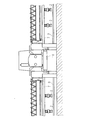
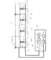
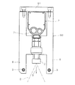
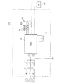
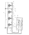
図1は、本発明の実施の形態1に係る静電噴霧装置1の要部構成を示す正面図である。また、図2は、静電噴霧装置1が備える噴霧ノズル2,2,…近傍を拡大した正面図であり、図3は、図2におけるIII −III 線の断面図である。更に、図4は、静電噴霧装置1が備える電源回路40の要部構成を示すブロック図である。
図1に示すように、静電噴霧装置1はブームスプレーヤであり、図示しない車輪を備える自走式の本体10と、本体10の左右両側に突出し、複数の噴霧ノズル2,2,…を支持する2本の支持杆7,7と、正電極として用いられる条状の導電部3,3,…とを備える。
FIG. 1 is a front view showing a main configuration of an
As shown in FIG. 1, the
図1及び図2に示すように、本体10には、約12Vの直流電圧を出力するバッテリ41と、バッテリ41から導電部3,3,…に給電するための電源回路40とが搭載され、更に、除草剤、植物生長調整剤等の薬液を貯留する貯留タンク61と、貯留タンク61に貯留されている薬液を加圧して噴霧ノズル2,2,…に供給するポンプ(圧液供給源)6とが搭載されている。
図2及び図4に示すように、電源回路40には、静電噴霧装置1をオン/オフするスイッチ43と、DC/DC変換器を用いてなるインバータ4と、インバータ4の出力電圧を調整する電圧調整部44とを備える。
As shown in FIGS. 1 and 2, the
As shown in FIGS. 2 and 4, the
インバータ4は、入力端子がスイッチ43を介してバッテリ41に接続されており、スイッチ43がオンである場合にバッテリ41の出力電圧を約4500V〜約15000V(通常約9000V)に昇圧する。また、インバータ4の正側の出力端子は、複数本(図4中3本)の導電部3,3,…に、各1個の抵抗器5,5,…を介在して接続されており、インバータ4の負側の出力端子は、貯留タンク61に貯留されている薬液に対してグランドされている。
このように、インバータ4は、導電部3,3,…に給電する高電圧電源装置として機能する。
The
Thus, the
インバータ4の出力端子における電流値は約10μAであるが、各抵抗器5は、導電部3に流れる電流値を最大で数μA、通常1μA以下に制限する。このため、導電部3から漏電した電流に使用者が触れても感電することが抑制されており、また、導電部3から漏電した電流がショートしても過電流が発生することが抑制されている。なお、上述した数値は一例であり、これらに限定されるものではない。
このように過電流の発生が抑制されているため、過電流によって使用者が感電することや、過電流によってインバータ4が故障する又は破壊されることが抑制されている。つまり、静電噴霧装置1は安全性が向上されており、漏電、過電流等に耐え得る大型のインバータを備える必要がないため、小型のインバータ4を用いて軽量且つ安価に構成されている。
Although the current value at the output terminal of the
As described above, since the occurrence of overcurrent is suppressed, it is possible to suppress the user from receiving an electric shock due to the overcurrent and the failure or destruction of the
電源ランプ45はスイッチ43がオンである場合に点灯し、3個の静電ランプ46,46,…は、対応する導電部3,3,…に正常な範囲の電流値を有する電流が流れている場合に点灯する。
なお、インバータ4から導電部3,3,…に供給される電流値及び電圧値夫々を検出して表示する電流・電圧モニタを本体10に備えてもよい。
The
The
図2及び図3に示すように、各支持杆7に関し、噴霧ノズル2,2,…夫々は、噴霧ノズル2から噴霧される液体の噴霧方向(図中矢符S方向)を下向きにして、支持杆7の長手方向に略等間隔に並設されている。
支持杆7は中空であり、支持杆7の下部に、ポンプ6によって供給された薬液が流通する流通管71が支持杆7に沿って設けられており、流通管71と、各噴霧ノズル2の噴霧口とが連結されている。
ポンプ6によって貯留タンク61から供給された薬液は、流通管71を流通して各噴霧ノズル2へ供給され、噴霧ノズル2は、噴霧口から矢符S方向へ、液体を噴霧する。図中Dは、噴霧ノズル2から噴霧される液体の拡散範囲であり、拡散範囲Dは、噴霧ノズル2の噴霧口を頂点とする円錐状又は扇状である。
As shown in FIGS. 2 and 3, the
The
The chemical liquid supplied from the
本実施の形態においては、噴霧ノズル2,2,…夫々から噴霧される液体を誘電帯電させるための帯電部として、液体の拡散範囲Dを介在して(即ち拡散範囲Dを間に挟むようにして)互いに略平行に離隔配置されている2本の導電部3,3が備えられている。
各導電部3は、銅線、鋼管等の1本の導電部材を用いてなる。つまり、1本の支持杆7に対して2本の導電部材が導電部3,3として配されている。
なお、U字状に配された1本の導電部材の往路と復路とを導電部3,3となす構成でもよい。また、導電部3,3を、例えば合成樹脂製の絶縁性被膜で被覆してもよい。この場合、導電部3に触れた使用者が感電することが更に抑制される。
In the present embodiment, the liquid sprayed from each of the
Each
In addition, a configuration in which the forward path and the return path of one conductive member arranged in a U-shape are the
このような導電部3,3は、噴霧ノズル2,2,…夫々から噴霧される液体に十分に誘導帯電可能であり、且つ、噴霧ノズル2,2,…からの液体の噴霧を阻害したり導電部3,3に付着した薬液が噴霧ノズル2,2,…へ流入したりすることが十分に抑制される距離だけ、噴霧ノズル2,2,…から離隔配置されている。
Such
また、各導電部3は、図2に示すように、支持杆7の長手方向に複数離隔配置されている支持部8,8,…間に装架されている。隣り合う支持部8,8間の離隔距離は、例えば導電部3の中央部が過剰に垂れ下がらない程度に設定されている。
更に、図3に示すように、導電部3,3に対応する支持部8,8は、H字状の支持板80の2本の下端部であり、噴霧ノズル2,2,…に係る噴霧方向(即ち矢符S方向)に夫々突出している。
Further, as shown in FIG. 2, each
Further, as shown in FIG. 3, the
一方、支持板80の2本の上端部は、棒状の連結部材81の両端部にネジ留めされており、この連結部材81の長手方向中央部下側が支持杆7の上部に取り付けられている。このような支持板80,80,…夫々は、最も近い噴霧ノズル2,2,…から十分に離隔しており、噴霧ノズル2,2,…からの液体の噴霧を阻害すること、及び支持板80,80,…に付着した薬液が噴霧ノズル2,2,…へ流入することが抑制されている。
On the other hand, the two upper end portions of the
図2及び図3に示すように、導電部3,3に対応する支持部8,8、延いては支持板80及び連結部材81は、各噴霧ノズル2を囲繞しておらず、2枚の支持板80が3個の噴霧ノズル2,2,…を間に介在して配されている。つまり、これらは複数の噴霧ノズル2,2,…に共用されている。同様に、導電部3,3も、各噴霧ノズル2を囲繞することなく、複数の噴霧ノズル2,2,…に共用されている。
As shown in FIGS. 2 and 3, the
このため、多数の噴霧ノズル2,2,…を備えていても、従来の噴霧ノズル毎に設けられる環状電極及び環状電極の筒状のホルダに比べて、導電部3,3及び支持部8,8,…は軽量化されている。この結果、導電部3,3及び支持部8,8,…を支持する支持杆7が軽量化され、支持杆7の強度を向上させる必要もない。つまり、静電噴霧装置1が小型軽量化されている。
また、多数の噴霧ノズル2,2,…個々に設けられた電極に対して給電する複雑な電気配線を必要としないため、断線する可能性が低い。
For this reason, even if it has
In addition, since there is no need for complicated electrical wiring for supplying power to the electrodes provided for each of the
しかも、導電部3,3、支持板80,80,…等に付着した薬液は、噴霧ノズル2,2,…の噴霧口へ流入し難いため、導電部3,3からこの薬液に漏電したとしても、噴霧ノズル2,2,…の噴霧口に存在する薬液でショートすること、延いてはショートによる過電流の発生が抑制されている。
Moreover, since the chemical solution attached to the
以上のような静電噴霧装置1は、支持杆7,7の噴霧ノズル2,2,…から液体を噴霧させることによって、例えば圃場の農作物へ薬液を撒布する。このとき、導電部3,3,…に高電圧が供給されて、噴霧ノズル2,2,…から噴霧される液体に負の電荷が与えられる。
例えば植物の葉の近傍に負電荷が存在すると、葉は表面及び裏面夫々が正、内部が負に分極する。このため、負に帯電している液体が農作物の表面にひきつけられて、葉の表面にも裏面にも満遍なく付着する。
The
For example, when a negative charge is present near the leaves of a plant, the leaves are polarized positively on the front and back surfaces and negatively inside. For this reason, the negatively charged liquid is attracted to the surface of the crop and adheres evenly to the front and back surfaces of the leaves.
なお、充放電可能なバッテリ41の代わりに、使いきりの電池を備えてもよい。また、導電部3,3,…にインバータ4の負側の出力端子を接続することによって導電部3,3,…を負電極となし、薬液に正電荷を与える構成でもよい。
更に、静電噴霧装置1は、自走式に限定されず、トラクタのような作業車に搭載されるタイプ、地面に設置されるタイプ、使用者が携帯するタイプ等でもよい。更にまた、静電噴霧装置1は、噴霧ノズル2を1個又は少数備える構成でもよい。
また、導電部3の代わりに、棒状又は管状の導電部を用いてもよい。
Instead of the chargeable /
Furthermore, the
Further, instead of the
実施の形態 2.
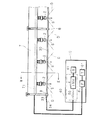
図5は、本発明の実施の形態2に係る静電噴霧装置が備える噴霧ノズル近傍を拡大した正面図である。
本実施の形態における静電噴霧装置は、実施の形態1の静電噴霧装置1と略同様であるが、噴霧ノズル2,2,…の代わりに、三方切替ノズルを用いてなる噴霧ノズル20,20,…を備えている。その他、実施の形態1に対応する部分には同一符号を付してそれらの説明を省略する。
FIG. 5 is an enlarged front view of the vicinity of the spray nozzle provided in the electrostatic spray device according to
The electrostatic spraying device in the present embodiment is substantially the same as the
このような静電噴霧装置は、各噴霧ノズル20が備える3個の噴霧部夫々で簡易に静電効果が得られ、また、実施の形態1の静電噴霧装置1と同様、過電流の発生が抑制され、更に、導電部3,3,…が軽量化されている。
つまり、本発明の静電噴霧装置は、噴霧ノズルの形状、噴霧形態等に関わらず、安全性の向上、装置の小型軽量化等の効果を奏する。
In such an electrostatic spraying device, an electrostatic effect can be easily obtained by each of the three spraying portions provided in each
That is, the electrostatic spraying device of the present invention has the effects of improving safety and reducing the size and weight of the device regardless of the shape of the spray nozzle, the spraying form, and the like.
ところで、従来のように、各噴霧ノズルに対して環状電極を配している場合は、噴霧ノズルの形状、サイズ等に応じて環状電極を取り替える必要があるが、導電部3,3は各噴霧ノズル2,20に個別に設けられておらず、複数の噴霧ノズル2,2,…又は噴霧ノズル20,20,…が共用しているため、実施の形態1の噴霧ノズル2,2,…に対応する導電部3,3が噴霧ノズル20,20,…に対して流用可能である。
つまり、異なる態様の静電噴霧装置が簡易に構成されている。
By the way, when the annular electrode is arranged for each spray nozzle as in the prior art, it is necessary to replace the annular electrode according to the shape, size, etc. of the spray nozzle. The
That is, the electrostatic spray apparatus of a different aspect is simply comprised.
実施の形態 3.
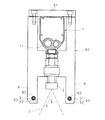
図6は、本発明の実施の形態3に係る静電噴霧装置が備える噴霧ノズル近傍を拡大した正面図であり、図7は、図6におけるVII −VII 線の断面図である。
本実施の形態における静電噴霧装置は、実施の形態1の静電噴霧装置1と略同様であるが、抵抗器5,5,…の代わりに抵抗器50,50,…を備え、導電部3,3,…の代わりに、支持部8,8,…間に装架されている被覆電線30,30,…、及び被覆電線30,30,…と電源回路40との間に配設されている高圧電線34,34,…を備えている。
6 is an enlarged front view of the vicinity of the spray nozzle provided in the electrostatic spray device according to
The electrostatic spray device in the present embodiment is substantially the same as the
各被覆電線30は、防水コネクタ33を介して高圧電線34に接続されており、高圧電線34と電源回路40内のインバータ4の正側の出力端子とは電源回路40内の各抵抗器50を介在して接続されている。
また、各被覆導線30は、導電部31を非絶縁部32で被覆してなり、支持部8に形成されている孔に、円筒状の緩衝材82を介して挿通されている。
その他、実施の形態1に対応する部分には同一符号を付してそれらの説明を省略する。
Each covered
Each covered
Other parts corresponding to those in the first embodiment are denoted by the same reference numerals, and description thereof is omitted.
ところで、実施の形態1において、導電部3に流れる電流値を最大で数μA、通常1μA以下に制限するためには、一般に、大型で高価な抵抗器5,5,…を備える必要がある。
一方、本実施の形態においては、抵抗器5の代わりに、小型で安価な抵抗器50を備えることによって、装置全体の小型化と低コスト化を図っている。しかしながら、抵抗器50は一般に抵抗器5よりも抵抗値が低いため、導電部31に流れる電流値を最大で数μA、通常1μA以下に制限することは困難である。
Incidentally, in the first embodiment, in order to limit the value of the current flowing through the
On the other hand, in the present embodiment, instead of the
このために、本実施の形態においては、導電部31を非絶縁部32で被覆することによって、非絶縁部32の表面に流れる電流値が最大で数μA、通常1μA以下に制限されるようにしてある。
この結果、使用者、圃場の農作物等が、数μAを超える電流が流れる導電部31に直接的に触れることが防止されており、また、非絶縁部32又は非絶縁部32から漏電した数μA以下の電流に使用者が触れても感電することが抑制されている。更に、非絶縁部32から漏電した電流がショートしても過電流が発生することが抑制されている。
For this reason, in this embodiment, by covering the
As a result, it is possible to prevent a user, a farm product, etc. from directly touching the
ところで、導電部31に印加される電圧が5000Vのような比較的低い値である場合、薬液に生じる電荷が小さくなるため、農作物のような被噴霧対象に薬液が付着する力も小さくなる。特に、薬液が噴霧ノズル2,2,…から下向きに噴霧されるときは、薬液には噴霧力と重力とが下向きに掛かるため、薬液は、例えば農作物の葉の上側には十分に付着したとしても、静電効果によって噴霧力及び重力の両方を打ち消して薬液を上昇させるだけの付着力が得られなければ、農作物の葉の下側には付着し難い。
By the way, when the voltage applied to the
このような不都合を解決するために、導電部31に印加される電圧を9000Vのような高電圧に設定することが考えられる。この場合でも、非絶縁部32に流れる電流は数μA以下の低電流であるため、使用者が感じるレベルにはならない。
なお、抵抗器5を抵抗器50に代えることなく、導電部3を被覆電線30に代えてもよい。この場合、非絶縁部32の表面に流れる電流値は更に制限される。
In order to solve such inconvenience, it can be considered that the voltage applied to the
Note that the
導電部31は、例えば銅線を用いてなり、非絶縁部32は、導電部31の表面を被覆する合成樹脂製、合成ゴム製等のチューブである。ただし、導電部31の表面に合成樹脂製、合成ゴム製等の被膜をコーティングすることによって非絶縁部32を形成してもよい。
非絶縁部32は、導電部31よりも導電性が低く、更に防水性を有する。しかしながら、導電性が低すぎて絶縁性を有することはない。本実施の形態においては、非絶縁部32として約1mmの厚さを有するナイロン製のチューブを用いているが、他の材料や他の厚みであってもよい。
The
The
このような非絶縁部32は、導電部31と外部の物体(例えば使用者、圃場の農作物等)との間に介在する抵抗器の役割を果たすため、導電部31を流れる電流値が高い電流が、導電部31から非絶縁部32を介して外部へ漏電することはない。しかも、非絶縁部32は防水性を有するため、非絶縁部32が薬液を吸い込むことで、吸い込んだ薬液を介した漏電が生じることもない。
更に、非絶縁部32は絶縁部ではないため、少なくとも1μA以下の必要十分な電流値を有する電流が非絶縁部32の表面に流れ、また、必要十分な電圧が印加される。この結果、導電部31が被覆されていても、噴霧ノズル2,2,…から噴霧される薬液が十分に帯電される。
Since such a
Further, since the
更にまた、非絶縁部32の一部に使用者、圃場の農作物等が直接的に触れることによって短絡が生じ、導電部31を流れていた電流の僅かな一部が地面へ漏電し多少電圧降下が生じたとしても、導電部31を流れていた電流のほとんどの残部が導電部31に流れ続ける。このため、非絶縁部32の残部(即ち使用者、圃場の農作物等が触れた部分以外)では、電圧降下が抑制されて、噴霧ノズル2,2,…から噴霧される薬液が十分に帯電される。
Furthermore, a short circuit occurs when a user, a farm product, or the like directly touches a part of the
仮に、導電部31が全く被覆されておらず、剥き出しのままである場合、使用者、圃場の農作物等が導電部31に直接的に触れる可能性が高い。
また、導電部31には電流値が比較的高い電流が流れるため、導電部31に直接的に触れた使用者が感電することがある。更に、使用者、圃場の農作物等が導電部31に直接的に触れることによって短絡が生じ、高電流値の電流が地面へ漏電して電圧が降下するため、導電部31全体で電流値の減少と電圧の降下とが過度に生じる。この結果、噴霧ノズル2,2,…から噴霧される薬液を十分に帯電させることができなくなる。
If the
In addition, since a current having a relatively high current value flows through the
このような不都合を解決するために、一般的な被覆導線のように、導電部31を絶縁部で被覆することが考えられる。この場合、導電部31を覆う絶縁部には電流がほとんど流れないため、使用者、作物等が触れることによる不都合は生じなくなる。
しかしながら、導電部を覆う絶縁部には電流が流れず電圧も印加されないため、絶縁部の周囲の空間において、噴霧ノズル2,2,…から噴霧される薬液が十分に帯電されないという不都合が生じる。
In order to solve such an inconvenience, it is conceivable to cover the
However, since no current flows and no voltage is applied to the insulating portion covering the conductive portion, there is a problem that the chemical liquid sprayed from the
つまり、本実施の形態の静電噴霧装置においては、被覆導線30を用いることによって、これらの不都合を同時的に解決している。
ところで、高圧電線34は薬液を帯電させる用途には用いられないため、銅線を絶縁性のチューブで被覆してなる被覆電線を用いて高圧電線34を構成してもよい。
That is, in the electrostatic spraying device of the present embodiment, these disadvantages are simultaneously solved by using the coated
By the way, since the high voltage
以上のような静電噴霧装置は、実施の形態1の静電噴霧装置1と同様、過電流の発生が抑制され、更に、導電部3,3,…が軽量化されている。しかも、被覆電線30を用いることによって、導電部31から漏電する電流値を簡易な構成で制限している。この結果、薬液の帯電効率を維持しつつも使用者の感電が抑制される。
つまり、本発明の静電噴霧装置は、導電部3,3,…の構成に関わらず、安全性の向上、装置の小型軽量化等の効果を奏する。
なお、噴霧ノズル2,2,…の代わりに噴霧ノズル20を備えていてもよい。
The electrostatic spraying device as described above, like the
That is, the electrostatic spraying device of the present invention has the effects of improving safety and reducing the size and weight of the device regardless of the configuration of the
A
1 静電噴霧装置
2,20 噴霧ノズル
3 導電部(帯電部)
30 被覆電線(帯電部)
31 導電部
32 非絶縁部
4 インバータ
5,50 抵抗器
6 ポンプ(圧液供給源)
7 支持杆
8 支持部
S 矢符(噴霧方向)
D 拡散範囲
DESCRIPTION OF
30 Coated wire (Charging part)
31 Conducting
7
D Diffusion range
Claims (5)
該噴霧ノズルから噴霧される液体を帯電させるための帯電部と
を備える静電噴霧装置において、
前記帯電部に流れる電流値を制限する抵抗器が接続されていることを特徴とする静電噴霧装置。 A spray nozzle for spraying liquid;
An electrostatic spraying device comprising: a charging unit for charging a liquid sprayed from the spray nozzle;
An electrostatic spraying device, wherein a resistor for limiting a current value flowing through the charging unit is connected.
前記導電部は互いに略平行な条状であり、前記長手方向に複数離隔配置されている支持部間に装架されていることを特徴とする請求項2に記載の静電噴霧装置。 A plurality of the spray nozzles are juxtaposed in the longitudinal direction of the support rod that supports the spray nozzle,
The electrostatic spraying device according to claim 2, wherein the conductive portions are strips that are substantially parallel to each other, and are mounted between support portions that are spaced apart from each other in the longitudinal direction.
Priority Applications (1)
| Application Number | Priority Date | Filing Date | Title |
|---|---|---|---|
| JP2007140901A JP5129512B2 (en) | 2007-01-16 | 2007-05-28 | Electrostatic spraying equipment |
Applications Claiming Priority (3)
| Application Number | Priority Date | Filing Date | Title |
|---|---|---|---|
| JP2007007370 | 2007-01-16 | ||
| JP2007007370 | 2007-01-16 | ||
| JP2007140901A JP5129512B2 (en) | 2007-01-16 | 2007-05-28 | Electrostatic spraying equipment |
Publications (2)
| Publication Number | Publication Date |
|---|---|
| JP2008194673A true JP2008194673A (en) | 2008-08-28 |
| JP5129512B2 JP5129512B2 (en) | 2013-01-30 |
Family
ID=39754117
Family Applications (1)
| Application Number | Title | Priority Date | Filing Date |
|---|---|---|---|
| JP2007140901A Active JP5129512B2 (en) | 2007-01-16 | 2007-05-28 | Electrostatic spraying equipment |
Country Status (1)
| Country | Link |
|---|---|
| JP (1) | JP5129512B2 (en) |
Cited By (10)
| Publication number | Priority date | Publication date | Assignee | Title |
|---|---|---|---|---|
| JP2010104321A (en) * | 2008-10-31 | 2010-05-13 | Iseki & Co Ltd | Electrostatic spray apparatus of farm work vehicle |
| JP2010148441A (en) * | 2008-12-25 | 2010-07-08 | Iseki & Co Ltd | Self-propelled pest-controlling machine |
| JP2012005432A (en) * | 2010-06-25 | 2012-01-12 | Iseki & Co Ltd | Chemical spraying machine |
| JP2012024082A (en) * | 2010-06-24 | 2012-02-09 | Arimitsu Industry Co Ltd | Spray device |
| JP2012035170A (en) * | 2010-08-05 | 2012-02-23 | Minoru Industrial Co Ltd | Electric leakage preventing part |
| JP2013163154A (en) * | 2012-02-10 | 2013-08-22 | Minoru Industrial Co Ltd | Induction charging electrostatic spraying device |
| JP2019017304A (en) * | 2017-07-18 | 2019-02-07 | 有光工業株式会社 | Electrostatic spray nozzle, electrostatic spray device, spray method of electrostatic spray device, spray device and spray method of spray device |
| KR20200023465A (en) * | 2017-07-06 | 2020-03-04 | 바이엘 악티엔게젤샤프트 | Weed control device |
| JP2023104831A (en) * | 2022-01-18 | 2023-07-28 | みのる産業株式会社 | Inductive charging type electrostatic sprayer |
| EP4403266A4 (en) * | 2021-09-16 | 2025-09-24 | Arimitsu Ind | ELECTROSTATIC SPRAYING DEVICE |
Citations (6)
| Publication number | Priority date | Publication date | Assignee | Title |
|---|---|---|---|---|
| JPS5525108U (en) * | 1978-08-01 | 1980-02-18 | ||
| JPS61162124A (en) * | 1985-01-10 | 1986-07-22 | 農業機械化研究所 | Chemicals scattering apparatus |
| JPH01151856U (en) * | 1988-03-24 | 1989-10-19 | ||
| JPH05501675A (en) * | 1989-11-21 | 1993-04-02 | シックルズ、ジェイムズ・イー | electrostatic spray gun |
| JPH08187452A (en) * | 1994-12-28 | 1996-07-23 | Abb Ind Kk | Rotary atomizing head type coating device |
| JPH09155242A (en) * | 1995-12-08 | 1997-06-17 | Mesatsuku:Kk | Electrostatic flocking device |
-
2007
- 2007-05-28 JP JP2007140901A patent/JP5129512B2/en active Active
Patent Citations (6)
| Publication number | Priority date | Publication date | Assignee | Title |
|---|---|---|---|---|
| JPS5525108U (en) * | 1978-08-01 | 1980-02-18 | ||
| JPS61162124A (en) * | 1985-01-10 | 1986-07-22 | 農業機械化研究所 | Chemicals scattering apparatus |
| JPH01151856U (en) * | 1988-03-24 | 1989-10-19 | ||
| JPH05501675A (en) * | 1989-11-21 | 1993-04-02 | シックルズ、ジェイムズ・イー | electrostatic spray gun |
| JPH08187452A (en) * | 1994-12-28 | 1996-07-23 | Abb Ind Kk | Rotary atomizing head type coating device |
| JPH09155242A (en) * | 1995-12-08 | 1997-06-17 | Mesatsuku:Kk | Electrostatic flocking device |
Cited By (18)
| Publication number | Priority date | Publication date | Assignee | Title |
|---|---|---|---|---|
| JP2010104321A (en) * | 2008-10-31 | 2010-05-13 | Iseki & Co Ltd | Electrostatic spray apparatus of farm work vehicle |
| JP2010148441A (en) * | 2008-12-25 | 2010-07-08 | Iseki & Co Ltd | Self-propelled pest-controlling machine |
| JP2012024082A (en) * | 2010-06-24 | 2012-02-09 | Arimitsu Industry Co Ltd | Spray device |
| JP2012005432A (en) * | 2010-06-25 | 2012-01-12 | Iseki & Co Ltd | Chemical spraying machine |
| JP2012035170A (en) * | 2010-08-05 | 2012-02-23 | Minoru Industrial Co Ltd | Electric leakage preventing part |
| JP2013163154A (en) * | 2012-02-10 | 2013-08-22 | Minoru Industrial Co Ltd | Induction charging electrostatic spraying device |
| JP2020525687A (en) * | 2017-07-06 | 2020-08-27 | バイエル、アクチエンゲゼルシャフトBayer Aktiengesellschaft | Weed control equipment |
| KR20200023465A (en) * | 2017-07-06 | 2020-03-04 | 바이엘 악티엔게젤샤프트 | Weed control device |
| JP7166302B2 (en) | 2017-07-06 | 2022-11-07 | バイエル、アクチエンゲゼルシャフト | weed control equipment |
| KR102648591B1 (en) | 2017-07-06 | 2024-03-19 | 디스커버리 퍼체이서 코퍼레이션 | weed control device |
| US12075768B2 (en) | 2017-07-06 | 2024-09-03 | Discovery Purchaser Corporation | Weed control apparatus |
| JP2019017304A (en) * | 2017-07-18 | 2019-02-07 | 有光工業株式会社 | Electrostatic spray nozzle, electrostatic spray device, spray method of electrostatic spray device, spray device and spray method of spray device |
| JP2021182932A (en) * | 2017-07-18 | 2021-12-02 | 有光工業株式会社 | Spraying device and spraying method of spraying device |
| JP7175530B2 (en) | 2017-07-18 | 2022-11-21 | 有光工業株式会社 | Spraying device and spraying method of the spraying device |
| JP7175488B2 (en) | 2017-07-18 | 2022-11-21 | 有光工業株式会社 | Electrostatic spraying nozzle, electrostatic spraying device, and spraying method of electrostatic spraying device |
| EP4403266A4 (en) * | 2021-09-16 | 2025-09-24 | Arimitsu Ind | ELECTROSTATIC SPRAYING DEVICE |
| JP2023104831A (en) * | 2022-01-18 | 2023-07-28 | みのる産業株式会社 | Inductive charging type electrostatic sprayer |
| JP7807052B2 (en) | 2022-01-18 | 2026-01-27 | みのる産業株式会社 | Induction charging type electrostatic sprayer |
Also Published As
| Publication number | Publication date |
|---|---|
| JP5129512B2 (en) | 2013-01-30 |
Similar Documents
| Publication | Publication Date | Title |
|---|---|---|
| JP5129512B2 (en) | Electrostatic spraying equipment | |
| JP5334500B2 (en) | Power supply for vehicle | |
| EP0186353B1 (en) | Spraying apparatus | |
| RU2019122633A (en) | LOADING DEVICE FOR SUPPLYING LOADS | |
| US20220132831A1 (en) | Device for treating soil and method for operating such a device | |
| CA2790304C (en) | Aerial spraying apparatus | |
| JP6316625B2 (en) | Electrostatic spraying equipment | |
| JP6317578B2 (en) | Electrospray equipment | |
| CN113731660B (en) | Electrostatic spraying device and electrostatic spraying method | |
| CN114082541A (en) | Hotel epidemic prevention is electronic electrostatic spray rifle of hand-held type for disinfection | |
| WO2016067310A4 (en) | Manually controlled variable coverage high range electrostatic sprayer | |
| JP7580119B2 (en) | Electrostatic spraying device | |
| US20240382985A1 (en) | Electrostatic Spraying Device | |
| JP2008012459A (en) | Electrostatic application spreader | |
| US20250128277A1 (en) | Electrostatic Spraying Device | |
| RU2019122821A (en) | LOADING DEVICE FOR SUPPLYING LOAD IN A LIQUID | |
| ATE416976T1 (en) | TELESCOPIC REFUELING MAST FOR AIRCRAFT PROTECTED AGAINST LIGHTNING | |
| JP2006136814A (en) | Electrical leak prevention member | |
| WO2022027736A1 (en) | Handheld-type electric electrostatic spray gun for epidemic prevention and disinfection of hotels | |
| JP7410213B2 (en) | Battery assembly and electronic atomization device | |
| US20230033525A1 (en) | Powered sprayer | |
| CN215784196U (en) | Electrostatic liquid spraying device | |
| JP2006198573A (en) | Electrostatic sprayer | |
| JP7807052B2 (en) | Induction charging type electrostatic sprayer | |
| KR20130062257A (en) | Lubrication system and vehicle having a lubrication system |
Legal Events
| Date | Code | Title | Description |
|---|---|---|---|
| A621 | Written request for application examination |
Free format text: JAPANESE INTERMEDIATE CODE: A621 Effective date: 20100203 |
|
| A977 | Report on retrieval |
Free format text: JAPANESE INTERMEDIATE CODE: A971007 Effective date: 20120213 |
|
| A131 | Notification of reasons for refusal |
Free format text: JAPANESE INTERMEDIATE CODE: A131 Effective date: 20120221 |
|
| A521 | Request for written amendment filed |
Free format text: JAPANESE INTERMEDIATE CODE: A523 Effective date: 20120423 |
|
| TRDD | Decision of grant or rejection written | ||
| A01 | Written decision to grant a patent or to grant a registration (utility model) |
Free format text: JAPANESE INTERMEDIATE CODE: A01 Effective date: 20121016 |
|
| A01 | Written decision to grant a patent or to grant a registration (utility model) |
Free format text: JAPANESE INTERMEDIATE CODE: A01 |
|
| A61 | First payment of annual fees (during grant procedure) |
Free format text: JAPANESE INTERMEDIATE CODE: A61 Effective date: 20121102 |
|
| R150 | Certificate of patent or registration of utility model |
Ref document number: 5129512 Country of ref document: JP Free format text: JAPANESE INTERMEDIATE CODE: R150 Free format text: JAPANESE INTERMEDIATE CODE: R150 |
|
| FPAY | Renewal fee payment (event date is renewal date of database) |
Free format text: PAYMENT UNTIL: 20151109 Year of fee payment: 3 |
|
| R250 | Receipt of annual fees |
Free format text: JAPANESE INTERMEDIATE CODE: R250 |
|
| R250 | Receipt of annual fees |
Free format text: JAPANESE INTERMEDIATE CODE: R250 |
|
| R250 | Receipt of annual fees |
Free format text: JAPANESE INTERMEDIATE CODE: R250 |
|
| R250 | Receipt of annual fees |
Free format text: JAPANESE INTERMEDIATE CODE: R250 |
|
| R250 | Receipt of annual fees |
Free format text: JAPANESE INTERMEDIATE CODE: R250 |
|
| R250 | Receipt of annual fees |
Free format text: JAPANESE INTERMEDIATE CODE: R250 |
|
| R250 | Receipt of annual fees |
Free format text: JAPANESE INTERMEDIATE CODE: R250 |