JP2008192528A - Fuel cell power generating device and its ventilating device - Google Patents
Fuel cell power generating device and its ventilating device Download PDFInfo
- Publication number
- JP2008192528A JP2008192528A JP2007027570A JP2007027570A JP2008192528A JP 2008192528 A JP2008192528 A JP 2008192528A JP 2007027570 A JP2007027570 A JP 2007027570A JP 2007027570 A JP2007027570 A JP 2007027570A JP 2008192528 A JP2008192528 A JP 2008192528A
- Authority
- JP
- Japan
- Prior art keywords
- fuel
- motor chamber
- fuel cell
- chamber
- exhaust
- Prior art date
- Legal status (The legal status is an assumption and is not a legal conclusion. Google has not performed a legal analysis and makes no representation as to the accuracy of the status listed.)
- Pending
Links
Images


Classifications
-
- Y—GENERAL TAGGING OF NEW TECHNOLOGICAL DEVELOPMENTS; GENERAL TAGGING OF CROSS-SECTIONAL TECHNOLOGIES SPANNING OVER SEVERAL SECTIONS OF THE IPC; TECHNICAL SUBJECTS COVERED BY FORMER USPC CROSS-REFERENCE ART COLLECTIONS [XRACs] AND DIGESTS
- Y02—TECHNOLOGIES OR APPLICATIONS FOR MITIGATION OR ADAPTATION AGAINST CLIMATE CHANGE
- Y02E—REDUCTION OF GREENHOUSE GAS [GHG] EMISSIONS, RELATED TO ENERGY GENERATION, TRANSMISSION OR DISTRIBUTION
- Y02E60/00—Enabling technologies; Technologies with a potential or indirect contribution to GHG emissions mitigation
- Y02E60/30—Hydrogen technology
- Y02E60/50—Fuel cells
Abstract
Description
この発明は、燃料電池本体などを収容する燃料・モータ室(本体室)とインバータなどを収容する電気室とに区画された筐体を有する燃料電池発電装置とその換気装置に関する。 The present invention relates to a fuel cell power generation device having a housing partitioned into a fuel / motor chamber (main body chamber) for accommodating a fuel cell main body and the like and an electric chamber for accommodating an inverter and the like, and a ventilator for the same.
燃料が有している化学エネルギーを直接電気に変換するシステムとして燃料電池が知られている。この燃料電池は、燃料である水素と酸化剤である酸素とを電気化学的に反応させて直接電気を取り出すものであり、高い発電効率で電気エネルギーを取り出すことができると同時に、静かで有害排気を出さないという環境性に優れた特徴を有する発電装置である。特に、最近では小型のPEFC(固体高分子形燃料電池)の開発が活性化し、家庭用燃料電池システムの普及も間近な状況となっている。 A fuel cell is known as a system that directly converts chemical energy contained in fuel into electricity. This fuel cell is one that takes out electricity directly by electrochemically reacting hydrogen as fuel and oxygen as oxidant, and can take out electric energy with high power generation efficiency, and at the same time, quiet and harmful exhaust This is a power generation device having an environmentally friendly feature that does not emit light. In particular, the development of small PEFC (solid polymer fuel cells) has recently been activated, and the spread of household fuel cell systems is imminent.
ところで、この燃料電池発電装置は、水素発生装置(燃料改質装置)、発電部である燃料電池本体、燃料電池本体より発電された直流電圧を交流電圧に変換するインバータ、制御装置、熱交換器、反応器、回転器などから構成されている。これらの構成要素は1つまたは複数のエンクロージャ(筐体)に収容され、一体のパッケージ内に組み込まれている。したがって、都市ガスやLPGなど化石燃料を使用する当該燃料電池発電装置において、パッケージ換気による可燃性ガス漏洩管理やプロセス排気に対する外部環境性維持は、安定した運転を継続させるために重要なものとなっている。 By the way, this fuel cell power generation device includes a hydrogen generator (fuel reforming device), a fuel cell main body that is a power generation unit, an inverter that converts a DC voltage generated by the fuel cell main body into an AC voltage, a control device, and a heat exchanger. , Reactor, rotator and the like. These components are housed in one or more enclosures (housings) and are incorporated into an integral package. Therefore, in the fuel cell power generation apparatus using fossil fuels such as city gas and LPG, the management of combustible gas leakage by package ventilation and the maintenance of the external environment for process exhaust are important for maintaining stable operation. ing.
図4は、従来の燃料電池発電装置のパッケージ換気とプロセス排気構造を示す図である。筐体20は隔壁21によって、燃料・モータ室2と電気室1とに区画されており、燃料・モータ室2には、水素発生装置(燃料改質装置)、燃料電池本体、熱交換器、反応器、回転器などが収容されている。一方、電気室1には、燃料電池本体より発電された直流電圧を交流電圧に変換するインバータ、制御装置などの電気品が収容されている。
FIG. 4 is a view showing a package ventilation and a process exhaust structure of a conventional fuel cell power generator. The
燃料・モータ室2には換気ファン4が設けられ、吸気口3から取り入れられた空気が前記機器類周辺を通過し、換気ファン4によりプロセス排気8と混合され、外部パネルにより下部側面に導入された後、パッケージ外へ放出される。さらに、換気ファン4入口には可燃性ガス検知器6が取り付けられ、万が一パッケージ内で可燃性ガスが一定量以上漏洩した場合は、可燃性ガス検知器6による漏洩検知により、燃料電池発電装置は保護停止される。
The fuel /
さらに、外部環境性維持という観点から、燃料電池発電装置からの排気ガスを建物の屋根部または側壁に設けたダクトもしくは煙突から導出する方法(特許文献1)などが提案されている。また、可燃性ガス漏洩管理という面では、パッケージ側面上部から燃料電池発電装置の排気ガスを排出する構造(特許文献2,3)などが提案されている。
上述のように、これまでの提案は外部環境性や可燃性ガス漏洩管理という面で一定の効果が得られているが、排気構造が複雑であった。 As described above, the proposals so far have obtained certain effects in terms of external environment and flammable gas leakage management, but the exhaust structure is complicated.
そこで、本発明は、燃料電池装置のパッケージ換気とプロセス排気の更なる最適化を図り、可燃性ガス漏洩管理という面からも効率的な燃料電池装置とその換気装置を提供することを目的とする。 Therefore, the present invention aims to further optimize the package ventilation and process exhaust of the fuel cell device, and to provide an efficient fuel cell device and its ventilation device from the viewpoint of flammable gas leakage management. .
上記目的を達成するために、本発明に係る燃料電池発電装置は、隔壁によって燃料・モータ室と電気室とに区画された筐体と、前記燃料・モータ室内に収容された燃料電池本体および改質装置と、前記電気室内に収容されて前記燃料電池本体で生じた直流を交流に変換するインバータと、前記電気室内に収容されて前記燃料電池本体を制御する制御装置と、前記燃料・モータ室内の上部に配置されて前記燃料・モータ室内の空気を吸い出す換気ファンと、前記換気ファンからの空気と前記燃料・モータ室内で生じたプロセス排気とを前記燃料・モータ室内の上部で吸い込んで前記燃料・モータ室の下部の排気口から前記筐体外に排出する排気ダクトと、を有し、前記電気室の下部に吸気口が形成され、その吸気口から前記電気室内に吸引された空気が、前記隔壁の隙間を通って前記燃料・モータ室内に導かれ、前記換気ファンおよび排気ダクトを介して前記プロセス排気とともに前記排気ダクトを通じて前記筐体の外部に排出されるように構成されていることを特徴とする。 In order to achieve the above object, a fuel cell power generator according to the present invention includes a housing partitioned by a partition into a fuel / motor chamber and an electric chamber, a fuel cell main body accommodated in the fuel / motor chamber, and a modification. A control device for controlling the fuel cell body housed in the electrical chamber, an inverter that converts the direct current generated in the fuel cell body and generated in the fuel cell body into an alternating current, and a fuel and motor chamber A ventilation fan that is disposed above the fuel / motor chamber, and sucks air from the ventilation fan and process exhaust generated in the fuel / motor chamber at the upper portion of the fuel / motor chamber. An exhaust duct that discharges from the lower exhaust port of the motor chamber to the outside of the housing, and an intake port is formed in the lower portion of the electric chamber, and is sucked into the electric chamber from the intake port Air is guided into the fuel / motor chamber through the gap between the partition walls, and is discharged to the outside of the casing through the exhaust duct along with the process exhaust through the ventilation fan and the exhaust duct. It is characterized by being.
また、本発明に係る燃料電池発電装置の換気装置は、隔壁によって燃料・モータ室と電気室とに区画された筐体を有し、前記燃料・モータ室内に燃料電池本体および改質装置が収容され、前記燃料電池本体で生じた直流を交流に変換するインバータと前記燃料電池本体を制御する制御装置とが前記電気室内に収容されている燃料電池発電装置の換気装置であって、前記燃料・モータ室内の上部に配置されて前記燃料・モータ室内の空気を吸い出す換気ファンと、前記換気ファンからの空気と前記燃料・モータ室内で生じたプロセス排気とを前記燃料・モータ室内の上部で吸い込んで前記燃料・モータ室の下部の排気口から前記筐体外に排出する排気ダクトと、を有し、前記電気室の下部に吸気口が形成され、その吸気口から前記電気室内に吸引された空気が、前記隔壁の隙間を通って前記燃料・モータ室内に導かれ、前記換気ファンおよび排気ダクトを介して前記プロセス排気とともに前記排気ダクトを通じて前記筐体の外部に排出されるように構成されていることを特徴とする。 The ventilator of the fuel cell power generator according to the present invention has a housing partitioned into a fuel / motor chamber and an electrical chamber by a partition, and the fuel cell body and the reformer are accommodated in the fuel / motor chamber. A fuel cell generator ventilator in which an inverter that converts direct current generated in the fuel cell body into alternating current and a control device that controls the fuel cell body are housed in the electrical chamber, A ventilation fan that is disposed in the upper part of the motor chamber and sucks out air in the fuel / motor chamber, and sucks air from the ventilation fan and process exhaust generated in the fuel / motor chamber in the upper part of the fuel / motor chamber. An exhaust duct that discharges from the lower exhaust port of the fuel / motor chamber to the outside of the housing, and an intake port is formed in the lower portion of the electric chamber. The discharged air is guided into the fuel / motor chamber through the gap between the partition walls, and discharged to the outside of the casing through the exhaust duct and the process exhaust through the ventilation fan and the exhaust duct. It is characterized by being.
本発明によれば、燃料電池発電装置のパッケージ内の環境温度管理という面から効率的な換気構造を提供できる。 ADVANTAGE OF THE INVENTION According to this invention, the efficient ventilation structure can be provided from the surface of environmental temperature management in the package of a fuel cell power generation device.
以下、本発明の実施の形態について、図面を参照して説明する。ここで、互いに同一または類似の部分には共通の符号を付して、重複説明は省略する。 Embodiments of the present invention will be described below with reference to the drawings. Here, the same or similar parts are denoted by common reference numerals, and redundant description is omitted.
[第1の実施形態]
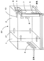
図1は、本発明に係る燃料電池発電装置の第1の実施形態を示す模式的斜視図である。
[First Embodiment]
FIG. 1 is a schematic perspective view showing a first embodiment of a fuel cell power generator according to the present invention.
燃料電池発電装置全体が一つの筐体20内に収容されている。筐体20は、隔壁21によって電気室1と燃料・モータ室2とに区画されている。燃料・モータ室2には、燃料電池本体のほか、改質装置(水素発生装置)、熱交換器、反応器、回転機など(図示を省略)が収容されている。また、電気室1には、燃料電池本体により発電された直流電圧を交流電圧に変換するインバータや、燃料電池発電装置を制御する制御装置などの電気品(図示を省略)が収容されている。
The entire fuel cell power generator is accommodated in one
隔壁21には隙間があって、電気室1と燃料・モータ室2の間を漏洩する空気流ができるようになっている。
There is a gap in the
電気室1の側壁下部には、外部空気を筐体20内に取り込むための吸気口3が設けられている。燃料・モータ室2の側壁近くの上部には換気ファン4が設けられ、燃料・モータ室2内のパッケージ空気10を、排気ダクト7を通じて外部に排出できるようになっている。排気ダクト7は燃料・モータ室2の上部から下部に向かって鉛直に延び、排気ダクト7の下部に設けられた排気口5が筐体20の外に向かって開いている。さらに、燃料電池本体や改質装置から排出されたプロセス排気8が排気ダクト7の上部に排出され、換気ファン4から送られた空気とともに排気ダクト7を通じて筐体20外に排出されるようになっている。
In the lower part of the side wall of the electric chamber 1, an
換気ファン4の上流側の燃料・モータ室2内には可燃性ガス検知器6が取り付けられている。万が一パッケージ内で可燃性ガスが一定量以上漏洩した場合は、可燃性ガス検知器6によってその漏洩が検知され、それによって燃料電池発電装置が保護停止されるようになっている。
A
この実施形態によれば、吸気口3から電気室1に流入して電気室1内を冷却した空気は、隔壁21の隙間を通って燃料・モータ室2へ流入し、排気ダクト7を通って筐体20外に排出される。吸気口3と換気ファン4がほぼ対角位置にあり、しかも、吸気口3が電気室1の下部に位置し、換気ファン4が燃料・モータ室2の上部に位置することから、筐体20内の滞留部を減らして効率よく換気することができる。
According to this embodiment, the air that has flowed into the electrical chamber 1 from the
この実施形態では、従来と異なり、外部パネルに特別な加工を施すことなく、安全に筐体20の下部側面から排気をすることができる。また、従来と比較して吸気口3の反対側側面に設置された換気ファン4により、空気の滞留部分が少ない換気が実現できる。また、換気ファン4の入口部に配置された可燃性ガス検知器6によって漏洩検知ができる。
In this embodiment, unlike the prior art, it is possible to safely exhaust air from the lower side surface of the
以上述べた構成・作用により、従来の換気ファンの仕様を変更することなく空気の滞留部分が少ない効率的な換気をすることが可能となり、安全性の面で優れた機能を発揮できる。 With the configuration and operation described above, it is possible to perform efficient ventilation with less air retention without changing the specifications of the conventional ventilation fan, and it is possible to exhibit an excellent function in terms of safety.
[第2の実施形態]
図2は,本発明に係る燃料電池発電装置の第2の実施形態を示す模式的斜視図である。この実施形態では、第1の実施形態と異なり、排気ダクト7の底面に排気口5を設け、外部パネルに特別な加工を施すことなく、安全にパッケージ下部から排気をすることができる。
[Second Embodiment]
FIG. 2 is a schematic perspective view showing a second embodiment of the fuel cell power generator according to the present invention. In this embodiment, unlike the first embodiment, an
また、排気口5を底面に配置することにより、雨水や粉塵など異物の混入を可及的に防ぐことができ、安定した燃料電池発電装置の運転を継続できる。
Further, by arranging the
以上述べた構成・作用により、従来の換気ファンの仕様を変更することなく空気の滞留部分が少ない効率的な換気をすることが可能となり、安全性の面で優れた機能を発揮できる。 With the configuration and operation described above, it is possible to perform efficient ventilation with less air retention without changing the specifications of the conventional ventilation fan, and it is possible to exhibit an excellent function in terms of safety.
[第3の実施形態]
図3は、本発明に係る燃料電池発電装置の第3の実施形態における排気ダクトを示す模式的斜視図である。この排気ダクト7は、第1の実施形態の燃料電池発電装置(図1)と同様に、燃料・モータ室2内に配置される。排気ダクト7の上部にはプロセス排気入口9とパッケージ空気入口11とが設けられている。また、排気ダクト7の底部にはドレン排出口13が設けられている。また、排気ダクト7の内面には吸音材12が取り付けられている。
[Third Embodiment]
FIG. 3 is a schematic perspective view showing an exhaust duct in the third embodiment of the fuel cell power generator according to the present invention. The
燃料・モータ室2内のパッケージ空気10はパッケージ空気入口11から排気ダクト7上部に導入され、燃料電池本体などからのプロセス排気8はプロセス排気入口9から排気ダクト7上部に導入されて、排気ダクト7内で混合する。排気ダクト7内の混合ガスは、排気ダクト7下部側面の排気口5から、外部へ放出される。一方、排気ダクト7底面に溜まった凝縮水はドレン排水口13から外部に排水される。
The
この実施形態によれば、第1および第2の実施形態における機能に加え、換気ファンの騒音を可及的に低減することにより、外部環境面でも優れた機能を発揮できる。 According to this embodiment, in addition to the functions in the first and second embodiments, an excellent function can be exhibited in terms of the external environment by reducing the noise of the ventilation fan as much as possible.
1…電気室
2…燃料・モータ室
3…吸気口
4…換気ファン
5…排気口
6…可燃性ガス検知器
7…排気ダクト
8…プロセス排気
9…プロセス排気入口
10…パッケージ空気
11…パッケージ空気入口
12…吸音材
13…ドレン排水口
20…筐体
21…隔壁
DESCRIPTION OF SYMBOLS 1 ...
Claims (6)
前記燃料・モータ室内に収容された燃料電池本体および改質装置と、
前記電気室内に収容されて前記燃料電池本体で生じた直流を交流に変換するインバータと、
前記電気室内に収容されて前記燃料電池本体を制御する制御装置と、
前記燃料・モータ室内の上部に配置されて前記燃料・モータ室内の空気を吸い出す換気ファンと、
前記換気ファンからの空気と前記燃料・モータ室内で生じたプロセス排気とを前記燃料・モータ室内の上部で吸い込んで前記燃料・モータ室の下部の排気口から前記筐体外に排出する排気ダクトと、
を有し、
前記電気室の下部に吸気口が形成され、その吸気口から前記電気室内に吸引された空気が、前記隔壁の隙間を通って前記燃料・モータ室内に導かれ、前記換気ファンおよび排気ダクトを介して前記プロセス排気とともに前記排気ダクトを通じて前記筐体の外部に排出されるように構成されていることを特徴とする燃料電池発電装置。 A housing partitioned by a partition into a fuel / motor chamber and an electrical chamber;
A fuel cell body and a reformer housed in the fuel / motor chamber;
An inverter that is housed in the electrical chamber and converts direct current generated in the fuel cell body into alternating current;
A control device that is housed in the electric chamber and controls the fuel cell body;
A ventilation fan that is arranged in the upper part of the fuel / motor chamber and sucks out air in the fuel / motor chamber;
An exhaust duct that sucks air from the ventilation fan and process exhaust generated in the fuel / motor chamber at the upper part of the fuel / motor chamber and exhausts the exhaust from the exhaust port at the lower part of the fuel / motor chamber;
Have
An air inlet is formed in the lower part of the electric chamber, and air sucked into the electric chamber from the air inlet is led into the fuel / motor chamber through the gap of the partition wall, and is passed through the ventilation fan and the exhaust duct. The fuel cell power generator is configured to be discharged to the outside of the casing through the exhaust duct together with the process exhaust.
前記燃料・モータ室内の上部に配置されて前記燃料・モータ室内の空気を吸い出す換気ファンと、
前記換気ファンからの空気と前記燃料・モータ室内で生じたプロセス排気とを前記燃料・モータ室内の上部で吸い込んで前記燃料・モータ室の下部の排気口から前記筐体外に排出する排気ダクトと、
を有し、
前記電気室の下部に吸気口が形成され、その吸気口から前記電気室内に吸引された空気が、前記隔壁の隙間を通って前記燃料・モータ室内に導かれ、前記換気ファンおよび排気ダクトを介して前記プロセス排気とともに前記排気ダクトを通じて前記筐体の外部に排出されるように構成されていることを特徴とする燃料電池発電装置の換気装置。 It has a housing partitioned into a fuel / motor chamber and an electric chamber by a partition wall, and a fuel cell body and a reformer are housed in the fuel / motor chamber, and converts direct current generated in the fuel cell body into alternating current. An inverter and a control device for controlling the fuel cell main body are a ventilator for a fuel cell power generator housed in the electric chamber,
A ventilation fan that is arranged in the upper part of the fuel / motor chamber and sucks out air in the fuel / motor chamber;
An exhaust duct that sucks air from the ventilation fan and process exhaust generated in the fuel / motor chamber at the upper part of the fuel / motor chamber and exhausts the exhaust from the exhaust port at the lower part of the fuel / motor chamber;
Have
An air inlet is formed in the lower part of the electric chamber, and air sucked into the electric chamber from the air inlet is led into the fuel / motor chamber through the gap between the partition walls, and is passed through the ventilation fan and the exhaust duct. A ventilator for a fuel cell power generator, wherein the ventilator is configured to be discharged to the outside of the casing through the exhaust duct together with the process exhaust.
Priority Applications (1)
| Application Number | Priority Date | Filing Date | Title |
|---|---|---|---|
| JP2007027570A JP2008192528A (en) | 2007-02-07 | 2007-02-07 | Fuel cell power generating device and its ventilating device |
Applications Claiming Priority (1)
| Application Number | Priority Date | Filing Date | Title |
|---|---|---|---|
| JP2007027570A JP2008192528A (en) | 2007-02-07 | 2007-02-07 | Fuel cell power generating device and its ventilating device |
Publications (2)
| Publication Number | Publication Date |
|---|---|
| JP2008192528A true JP2008192528A (en) | 2008-08-21 |
| JP2008192528A5 JP2008192528A5 (en) | 2009-07-09 |
Family
ID=39752418
Family Applications (1)
| Application Number | Title | Priority Date | Filing Date |
|---|---|---|---|
| JP2007027570A Pending JP2008192528A (en) | 2007-02-07 | 2007-02-07 | Fuel cell power generating device and its ventilating device |
Country Status (1)
| Country | Link |
|---|---|
| JP (1) | JP2008192528A (en) |
Cited By (9)
| Publication number | Priority date | Publication date | Assignee | Title |
|---|---|---|---|---|
| WO2010122700A1 (en) * | 2009-04-22 | 2010-10-28 | パナソニック株式会社 | Fuel battery system |
| US20110303482A1 (en) * | 2010-06-15 | 2011-12-15 | Aisin Seiki Kabushiki Kaisha | Outdoor power generating apparatus |
| WO2012090964A1 (en) * | 2010-12-28 | 2012-07-05 | Jx日鉱日石エネルギー株式会社 | Fuel cell system |
| JP2012243595A (en) * | 2011-05-20 | 2012-12-10 | Noritz Corp | Fuel cell power generation equipment |
| JP2014032753A (en) * | 2012-08-01 | 2014-02-20 | Toshiba Fuel Cell Power Systems Corp | Fuel cell system |
| JP2017212084A (en) * | 2016-05-24 | 2017-11-30 | 京セラ株式会社 | Fuel cell device |
| JP2018022602A (en) * | 2016-08-03 | 2018-02-08 | パナソニックIpマネジメント株式会社 | Fuel cell system |
| JP2020047535A (en) * | 2018-09-21 | 2020-03-26 | パナソニックIpマネジメント株式会社 | Fuel cell system |
| JP7340753B2 (en) | 2017-12-21 | 2023-09-08 | パナソニックIpマネジメント株式会社 | fuel cell system |
Citations (2)
| Publication number | Priority date | Publication date | Assignee | Title |
|---|---|---|---|---|
| JP2005142394A (en) * | 2003-11-07 | 2005-06-02 | Kokusai Denki Engineering:Kk | Heat dissipating structure of housing for electronic apparatus |
| JP2006228613A (en) * | 2005-02-18 | 2006-08-31 | Matsushita Electric Ind Co Ltd | Fuel cell power generation system |
-
2007
- 2007-02-07 JP JP2007027570A patent/JP2008192528A/en active Pending
Patent Citations (2)
| Publication number | Priority date | Publication date | Assignee | Title |
|---|---|---|---|---|
| JP2005142394A (en) * | 2003-11-07 | 2005-06-02 | Kokusai Denki Engineering:Kk | Heat dissipating structure of housing for electronic apparatus |
| JP2006228613A (en) * | 2005-02-18 | 2006-08-31 | Matsushita Electric Ind Co Ltd | Fuel cell power generation system |
Cited By (12)
| Publication number | Priority date | Publication date | Assignee | Title |
|---|---|---|---|---|
| WO2010122700A1 (en) * | 2009-04-22 | 2010-10-28 | パナソニック株式会社 | Fuel battery system |
| JPWO2010122700A1 (en) * | 2009-04-22 | 2012-10-25 | パナソニック株式会社 | Fuel cell system |
| US20110303482A1 (en) * | 2010-06-15 | 2011-12-15 | Aisin Seiki Kabushiki Kaisha | Outdoor power generating apparatus |
| WO2012090964A1 (en) * | 2010-12-28 | 2012-07-05 | Jx日鉱日石エネルギー株式会社 | Fuel cell system |
| JPWO2012090964A1 (en) * | 2010-12-28 | 2014-06-05 | Jx日鉱日石エネルギー株式会社 | Fuel cell system |
| JP2012243595A (en) * | 2011-05-20 | 2012-12-10 | Noritz Corp | Fuel cell power generation equipment |
| JP2014032753A (en) * | 2012-08-01 | 2014-02-20 | Toshiba Fuel Cell Power Systems Corp | Fuel cell system |
| JP2017212084A (en) * | 2016-05-24 | 2017-11-30 | 京セラ株式会社 | Fuel cell device |
| JP2018022602A (en) * | 2016-08-03 | 2018-02-08 | パナソニックIpマネジメント株式会社 | Fuel cell system |
| JP7340753B2 (en) | 2017-12-21 | 2023-09-08 | パナソニックIpマネジメント株式会社 | fuel cell system |
| JP2020047535A (en) * | 2018-09-21 | 2020-03-26 | パナソニックIpマネジメント株式会社 | Fuel cell system |
| JP7113309B2 (en) | 2018-09-21 | 2022-08-05 | パナソニックIpマネジメント株式会社 | fuel cell system |
Similar Documents
| Publication | Publication Date | Title |
|---|---|---|
| JP4950497B2 (en) | Fuel cell power generator and ventilation method thereof | |
| JP2008192528A (en) | Fuel cell power generating device and its ventilating device | |
| JP5078705B2 (en) | Fuel cell system | |
| JP4591872B2 (en) | Fuel cell device | |
| JP2006253020A (en) | Fuel cell generating device and intake and exhaust device | |
| WO2013122124A1 (en) | Fuel cell system | |
| JP2006140164A (en) | Fuel cell device | |
| WO2012114646A1 (en) | Fuel cell system | |
| JP4320774B2 (en) | Fuel cell device | |
| JP2006294409A (en) | Fuel cell power generator | |
| JP2007048704A (en) | Fuel cell apparatus | |
| KR100774472B1 (en) | Air preheating apparatus for fuel cell system | |
| JP2011119095A (en) | Fuel cell system | |
| JP2010262746A (en) | Fuel cell power generation system | |
| JP5381320B2 (en) | Reforming system and fuel cell system | |
| JP5444828B2 (en) | Fuel cell power generator | |
| JP6304601B2 (en) | Fuel cell cogeneration system | |
| JP5229121B2 (en) | Fuel cell device | |
| JP2005085642A (en) | Stationary fuel cell power generation system | |
| JP2016143624A (en) | Fuel battery power generation device | |
| JP2003151587A (en) | Fuel cell power generation system | |
| JP2007080655A (en) | Fuel cell power generator | |
| JP2005285427A (en) | Fuel cell device | |
| JP6229145B2 (en) | Fuel cell system | |
| WO2010122700A1 (en) | Fuel battery system |
Legal Events
| Date | Code | Title | Description |
|---|---|---|---|
| A521 | Written amendment |
Free format text: JAPANESE INTERMEDIATE CODE: A523 Effective date: 20090521 |
|
| A621 | Written request for application examination |
Free format text: JAPANESE INTERMEDIATE CODE: A621 Effective date: 20090521 |
|
| RD04 | Notification of resignation of power of attorney |
Free format text: JAPANESE INTERMEDIATE CODE: A7424 Effective date: 20110425 |
|
| A977 | Report on retrieval |
Free format text: JAPANESE INTERMEDIATE CODE: A971007 Effective date: 20120322 |
|
| A131 | Notification of reasons for refusal |
Free format text: JAPANESE INTERMEDIATE CODE: A131 Effective date: 20120403 |
|
| A521 | Written amendment |
Free format text: JAPANESE INTERMEDIATE CODE: A523 Effective date: 20120529 |
|
| A131 | Notification of reasons for refusal |
Free format text: JAPANESE INTERMEDIATE CODE: A131 Effective date: 20121002 |
|
| A02 | Decision of refusal |
Free format text: JAPANESE INTERMEDIATE CODE: A02 Effective date: 20130212 |