JP2008190367A - Electronically controlled throttle unit for internal combustion engine - Google Patents
Electronically controlled throttle unit for internal combustion engine Download PDFInfo
- Publication number
- JP2008190367A JP2008190367A JP2007023634A JP2007023634A JP2008190367A JP 2008190367 A JP2008190367 A JP 2008190367A JP 2007023634 A JP2007023634 A JP 2007023634A JP 2007023634 A JP2007023634 A JP 2007023634A JP 2008190367 A JP2008190367 A JP 2008190367A
- Authority
- JP
- Japan
- Prior art keywords
- throttle valve
- valve
- combustion engine
- internal combustion
- electronically controlled
- Prior art date
- Legal status (The legal status is an assumption and is not a legal conclusion. Google has not performed a legal analysis and makes no representation as to the accuracy of the status listed.)
- Pending
Links
Images


Abstract
Description
本発明は車載用エンジンの吸入空気量を電気的に制御する電子制御スロットルボディに関するものであり、特にスロットルバルブやスロットルシャフトが樹脂材料によって形成された電子制御スロットル装置に関するものである。 The present invention relates to an electronically controlled throttle body that electrically controls the intake air amount of a vehicle-mounted engine, and more particularly to an electronically controlled throttle device in which a throttle valve and a throttle shaft are formed of a resin material.
スロットルボディ,スロットルシャフトやスロットルバルブを樹脂化した電子制御スロットル装置では圧力変動や温度変化といった劣化要因に対し耐性が低下し、応力変動による疲労破壊や熱劣化であるクリープ変形に対し製品寿命が短くなるという問題がある。 Electronically controlled throttle devices that use resin for the throttle body, throttle shaft, and throttle valve are less resistant to deterioration factors such as pressure fluctuations and temperature changes, and have a shorter product life against creep damage due to fatigue failure and thermal deterioration due to stress fluctuations. There is a problem of becoming.
このような課題に対し、特開2004−251238号公報記載のものではバルブの肉厚を厚くする等の形状変更により応力を低減することで克服することが提案されている。 It has been proposed to overcome such problems by reducing the stress by changing the shape such as increasing the thickness of the valve in JP 2004-251238 A.
前述のように強度及び剛性を向上させるために樹脂スロットルバルブを厚肉化するとスロットルシャフト径よりスロットルバルブ幅の方が大きくなる。 As described above, when the resin throttle valve is thickened to improve the strength and rigidity, the throttle valve width becomes larger than the throttle shaft diameter.
その為、スロットルバルブの投影面積が増加し、空気抵抗が増大することで、エンジンへの吸入空気流量が減少し、最大出力が低下するという新たな課題に直面することになる。 As a result, the projected area of the throttle valve increases and the air resistance increases, which leads to a new problem that the intake air flow rate to the engine decreases and the maximum output decreases.
そこで本発明は、樹脂スロットルバルブを厚肉化し、強度及び剛性の向上を図るだけでは無く、スロットルバルブの投影面積の増加を可能な限り低減しエンジンの最大出力の低下を防ぐことを目的とした電子制御スロットル装置を提供する。 Therefore, the present invention aims to not only reduce the increase in the projected area of the throttle valve as much as possible and prevent a decrease in the maximum output of the engine, in addition to increasing the thickness and the strength and rigidity of the resin throttle valve. An electronically controlled throttle device is provided.
上記目的を達成するために、本発明は、少なくともエンジンへの吸入空気流量が最大となるスロットルバルブ全開位置で、空気が吸入空気の流れる方向に通過できる通路をスロットルバルブに設けたことを特徴とする電子制御スロットル装置を提案する。 In order to achieve the above object, the present invention is characterized in that the throttle valve is provided with a passage through which air can pass in the direction in which the intake air flows, at least at the throttle valve fully opened position where the intake air flow rate to the engine is maximum. An electronically controlled throttle device is proposed.
本発明のようにスロットルバルブに空気が通る通路を設けることで、樹脂製スロットルバルブの強度及び剛性を損なう事無く、エンジンの出力低下を防ぐ事ができ、また、空気通路設置により樹脂消費量も低減した低コストの電子制御スロットル装置を提供できる利点がある。 By providing a passage through which air passes through the throttle valve as in the present invention, it is possible to prevent a decrease in engine output without impairing the strength and rigidity of the resin throttle valve. There is an advantage that a reduced and low-cost electronic control throttle device can be provided.
本発明の一実施例としてスロットルシャフトと一体成形されたスロットルバルブを有する電子制御スロットル装置の詳細について、以下図面に従い説明する。 As an embodiment of the present invention, details of an electronically controlled throttle device having a throttle valve integrally formed with a throttle shaft will be described below with reference to the drawings.
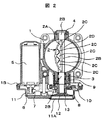
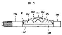
図1,図2及び図3は、それぞれ本発明の実施例であるスロットルバルブ2の縦断面図、電子制御スロットル装置全体の横断面図及び空気通路を有するスロットルバルブ2の形状を示す。
1, 2 and 3 show a longitudinal sectional view of a
本発明の対象である電子制御スロットル装置に関し説明する。 An electronically controlled throttle device that is an object of the present invention will be described.
スロットルボディ1は空気通路を形成し、また各種構成部品を支持している。
The
スロットルバルブのシャフト部2Bは、滑り軸受4及び転がり軸受3によって支持されており、スロットルバルブ2が回転すると、ボア内壁1A部の面積とスロットルバルブ2の投影面積の差が変化し、エンジンへの吸入空気流量が変化する仕様となっている。
The
ここでスロットルバルブ2は、従来別々の金属部品で構成されていたスロットルバルブ部2Aとスロットルバルブのシャフト(回転シャフトとも呼ぶ)部2Bを樹脂で一体成形した部品である。
Here, the
スロットルバルブ2のシャフト部2Bは、スロットルボディ1に支持されたモータ5の駆動力がモータギア6,中間ギア7及びスロットルギア8を介して伝達されることで回転する構成となっており、スロットルバルブ2の回転角はスロットルバルブ2のシャフト部2B先端に保持された角度検出センサの一部品であるロータ13とギアカバー11に保持されたロータ位置を検出するためのセンサ部によって検出される。センサ部は基板12に取付けられている。
The
そして、コントロールユニットがエンジンへ最適な空気流量を供給するために基板12により出力されるスロットルバルブ2の位置を検出しながらモータへ駆動信号を与えることで、スロットルバルブ2が回転し、吸入空気流量を制御する。基板12は、ギアカバー11の外部側から取付けられ、ふた11Aで覆われている。
The control unit gives a drive signal to the motor while detecting the position of the
上記は非接触式スロットルポジションセンサの構成を説明したが、本発明は角度検出装置の方式には依存せず、接触式スロットルポジションセンサであっても問題無い。 Although the above describes the configuration of the non-contact type throttle position sensor, the present invention does not depend on the method of the angle detection device, and there is no problem even if it is a contact type throttle position sensor.
また、スロットルボディ1とスロットルギア8の間には、スロットルバルブ2が閉じる方向へ付勢力を与える為のリターンスプリング9と、モータ5無通電時にスロットルバルブ2をある開度に保持する為のデフォルトスプリング10を有している。
A return spring 9 is provided between the
次に、本発明の特徴である前記スロットルバルブ2は、図3に示す様に強度,剛性の向上を目的にスロットルバルブ2のバルブ部2Aに膨らみを持った形状をし、さらに内部に空気が流れる空気通路2Cを有している。ここで、スロットルバルブ2は樹脂で成形されており、これによって、従来の金属材料では製作不可能であった前記形状のスロットルバルブ2の製作を可能にしている。
Next, the
このスロットルバルブ2は前述のとおりバルブ部2Aに膨らみを持った形状を有しているが、吸入空気は膨らみ部に沿って流れる為、エンジンへの吸入空気流量は膨らみ部の最大幅に依存し、結果としてエンジン出力低下を招く。
As described above, the
そこで本発明では、この課題を克服するためにスロットルバルブ2のバルブ部2Aに空気通路2Cを設け、空気が流れる仕様とした。
Therefore, in the present invention, in order to overcome this problem, an
この空気通路2Cは、スロットルバルブが図2に示すように全開点に位置した際に、スロットルバルブ部の投影面積を効率的に低減できる様に空気の流れと平行となるように設けている。
The
また、本図では空気通路2Cの数が5個且つ三角形状であるが、強度及び剛性が確保出来れば通路数,通路形状はどのような数量・形状でも同一効果を得ることができる。
In this figure, the number of the
図4は本発明の別の実施例である。実施例1に記載のスロットルバルブ2は空気通路
2Cをバルブ部2Aの内部に設けたが、図4に示すようにバルブ部2A表面上に空気流れ方向に延びるスリットのように設けても良く、この場合スリットの形状はどのような形状でもよい。このように空気通路2Cをバルブ部2A表面上に設けることで、バルブの強度を保ちつつも、空気吸入時の空気抵抗を低減でき、エンジンの最大出力の低下を防ぐことができる。
FIG. 4 shows another embodiment of the present invention. In the
図5,図6は本発明の別の実施例である。実施例1,実施例2記載のスロットルバルブ2において、図面で見てシャフト部2B中心軸より上側に空気通路2Cが設けられているが、図3,図4に示す形状では強度的に充分でない場合、図5,図6に示す様にバルブ部2Aの図面で見て中心軸より下側にも膨らみを持った形状にし、下側にも空気通路2Cを設けても良い。本実施例により、更に強度を向上する為にスロットルバルブ2のバルブ部2Aの厚さを厚くした場合でも空気抵抗の上昇を抑えられる。
5 and 6 show another embodiment of the present invention. In the
図7,図8は本発明の別の実施例である。本発明におけるスロットルバルブ2のバルブ部2Aが全閉時の外輪郭2D形状は、図7及び図8に示すような長円形状の形状にしても良い。外輪郭2Dを長円形状とする事で、同投影面積の真円形状のスロットルバルブ2と比較してバルブ回転中心からの回転半径が短くなり、スロットルバルブ2の開度が低開度領域での流量特性が改善される。
7 and 8 show another embodiment of the present invention. The
具体的には、低開度における増加角度あたりの増加流量が小さくなり、流量制御性が向上する。 Specifically, the increased flow rate per increase angle at a low opening is reduced, and the flow rate controllability is improved.
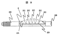
図9は本発明の別の実施例である。本実施例におけるスロットルバルブ2のバルブ部
2Aは全閉時の外輪郭2D形状が、図9に示すように中心より図面下側の部分だけにシャフト部2Bが形成されており、図面上側の部分には空気の流れに沿った5つの深い空気通路2Cとしての溝が形成されている。この空気通路2Cとしての溝はシャフト部2Bの上側半分の部分ではシャフト部2Bまで深くえぐるように形成されている。結果的にシャフト部2Bを形成する部分にも空気流路ができる。
FIG. 9 shows another embodiment of the present invention. The
その結果、全開時の空気流路断面積が大きくなり、流体抵抗が減る。又小中開度状態においては、スロットルバルブ2のバルブ部2Aにおいて、空気の流れが空気通路2Cとしての溝で整流され、スロットルシャフトに余計な力を作用させることがない。
As a result, the air channel cross-sectional area when fully opened increases and the fluid resistance decreases. Further, in the small and medium opening state, in the
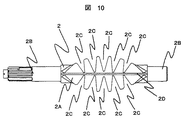
図10は本発明のさらに別の実施例である。本実施例におけるスロットルバルブ2のバルブ部2Aは全閉時の外輪郭2D形状が、図10に示すようにシャフトの中心より図面上下の部分に空気の流れに沿った5つの深い空気通路2Cとしての溝が形成されている。この空気通路2Cとしての溝はシャフト部2Bまで深くえぐるように形成されている。結果的にシャフト部2Bを形成する部分にも多くの空気流路ができる。
FIG. 10 shows still another embodiment of the present invention. The
その結果、全開時の空気流路断面積が大きくなり、流体抵抗が減る。又小中開度状態においては、スロットルバルブ2のバルブ部2Aにおいて、空気の流れが空気通路2Cとしての溝で整流され、スロットルシャフトに余計な力を作用させることがない。特にバルブの表と裏で、空気の流れが類似した流れになるので、よりスロットルシャフトに余計な力を作用させることがない。
As a result, the air channel cross-sectional area when fully opened increases and the fluid resistance decreases. Further, in the small and medium opening state, in the
本発明は、内燃機関の空気量を制御するスロットル装置のバタフライバルブとして用いると好適であるが、それに限ることなく樹脂材製バタフライバルブとして流体の流量制御に広く利用できる。 The present invention is preferably used as a butterfly valve of a throttle device for controlling the air amount of an internal combustion engine. However, the present invention is not limited to this and can be widely used for fluid flow control as a resin-made butterfly valve.
1 スロットルボディ
1A スロットルボディボア内壁部
2 スロットルバルブ
2A スロットルバルブのバルブ部
2B スロットルバルブのシャフト部
2C スロットルバルブの空気通路
2D スロットルバルブの全閉時外輪郭
3 転がり軸受
4 滑り軸受
5 モータ
6 モータギア
7 中間ギア
8 スロットルギア
9 リターンスプリング
10 デフォルトスプリング
11 ギアカバー
12 基板
13 ロータ
DESCRIPTION OF
Claims (7)
Priority Applications (1)
| Application Number | Priority Date | Filing Date | Title |
|---|---|---|---|
| JP2007023634A JP2008190367A (en) | 2007-02-02 | 2007-02-02 | Electronically controlled throttle unit for internal combustion engine |
Applications Claiming Priority (1)
| Application Number | Priority Date | Filing Date | Title |
|---|---|---|---|
| JP2007023634A JP2008190367A (en) | 2007-02-02 | 2007-02-02 | Electronically controlled throttle unit for internal combustion engine |
Publications (1)
| Publication Number | Publication Date |
|---|---|
| JP2008190367A true JP2008190367A (en) | 2008-08-21 |
Family
ID=39750698
Family Applications (1)
| Application Number | Title | Priority Date | Filing Date |
|---|---|---|---|
| JP2007023634A Pending JP2008190367A (en) | 2007-02-02 | 2007-02-02 | Electronically controlled throttle unit for internal combustion engine |
Country Status (1)
| Country | Link |
|---|---|
| JP (1) | JP2008190367A (en) |
Cited By (4)
| Publication number | Priority date | Publication date | Assignee | Title |
|---|---|---|---|---|
| JP2010090748A (en) * | 2008-10-06 | 2010-04-22 | Denso Corp | Intake device for internal combustion engine |
| JP2012017782A (en) * | 2010-07-07 | 2012-01-26 | Fuji Koki Corp | Butterfly valve |
| KR101260868B1 (en) | 2012-12-05 | 2013-05-06 | 동아대학교 산학협력단 | Knockdownable butterfly balve |
| CN104595504A (en) * | 2013-11-01 | 2015-05-06 | 华北电力大学 | Comb-shaped pulverized coal balance valve |
Citations (2)
| Publication number | Priority date | Publication date | Assignee | Title |
|---|---|---|---|---|
| JPH0814408A (en) * | 1994-06-28 | 1996-01-16 | Fuji Oozx Inc | Butterfly valve |
| JP2002527674A (en) * | 1998-10-21 | 2002-08-27 | フイルテルウエルク マン ウント フンメル ゲゼルシヤフト ミツト ベシユレンクテル ハフツング | Flap mechanism |
-
2007
- 2007-02-02 JP JP2007023634A patent/JP2008190367A/en active Pending
Patent Citations (2)
| Publication number | Priority date | Publication date | Assignee | Title |
|---|---|---|---|---|
| JPH0814408A (en) * | 1994-06-28 | 1996-01-16 | Fuji Oozx Inc | Butterfly valve |
| JP2002527674A (en) * | 1998-10-21 | 2002-08-27 | フイルテルウエルク マン ウント フンメル ゲゼルシヤフト ミツト ベシユレンクテル ハフツング | Flap mechanism |
Cited By (4)
| Publication number | Priority date | Publication date | Assignee | Title |
|---|---|---|---|---|
| JP2010090748A (en) * | 2008-10-06 | 2010-04-22 | Denso Corp | Intake device for internal combustion engine |
| JP2012017782A (en) * | 2010-07-07 | 2012-01-26 | Fuji Koki Corp | Butterfly valve |
| KR101260868B1 (en) | 2012-12-05 | 2013-05-06 | 동아대학교 산학협력단 | Knockdownable butterfly balve |
| CN104595504A (en) * | 2013-11-01 | 2015-05-06 | 华北电力大学 | Comb-shaped pulverized coal balance valve |
Similar Documents
| Publication | Publication Date | Title |
|---|---|---|
| JP2008175064A (en) | Butterfly valve device | |
| JP5955418B2 (en) | Mechanical coolant pump | |
| JP2008008172A (en) | Intake control valve | |
| JP2008190367A (en) | Electronically controlled throttle unit for internal combustion engine | |
| US6854709B2 (en) | Throttle valves having spherical shaped edges | |
| US20110114051A1 (en) | Air intake apparatus for internal combustion engine | |
| EP2333293B1 (en) | Air intake apparatus for internal combustion engine | |
| JP2009127522A (en) | Airflow control apparatus and manufacturing method thereof | |
| US11300220B2 (en) | Valve device | |
| JP2004339995A (en) | Intake valve device | |
| JP5429080B2 (en) | Throttle device | |
| JP4971242B2 (en) | Intake device for internal combustion engine | |
| JP2002349396A (en) | Bypass intake air amount control device | |
| JP2005113718A (en) | Bypass intake air quantity control device | |
| JP4219841B2 (en) | Throttle control device | |
| JP4234121B2 (en) | Engine intake system | |
| JP2010106738A (en) | Throttle device for internal combustion engine | |
| JP2009264114A (en) | Throttle valve control device of internal combustion engine | |
| KR101145630B1 (en) | Intake system of engine | |
| JP6805094B2 (en) | Internal combustion engine cooling system | |
| JP4805961B2 (en) | Throttle device | |
| JP2005256779A (en) | Variable intake device | |
| JP2005299413A5 (en) | ||
| JP2006291797A (en) | Inlet flow valve system | |
| JP2013096364A (en) | Gas flow rate control valve for internal combustion engine |
Legal Events
| Date | Code | Title | Description |
|---|---|---|---|
| A621 | Written request for application examination |
Free format text: JAPANESE INTERMEDIATE CODE: A621 Effective date: 20081224 |
|
| A711 | Notification of change in applicant |
Free format text: JAPANESE INTERMEDIATE CODE: A712 Effective date: 20100105 |
|
| A977 | Report on retrieval |
Effective date: 20100216 Free format text: JAPANESE INTERMEDIATE CODE: A971007 |
|
| A131 | Notification of reasons for refusal |
Effective date: 20100302 Free format text: JAPANESE INTERMEDIATE CODE: A131 |
|
| A02 | Decision of refusal |
Free format text: JAPANESE INTERMEDIATE CODE: A02 Effective date: 20100629 |