JP2008189727A - Bonded structure, bonding method, liquid droplet discharge head and method for producing liquid droplet discharge head - Google Patents
Bonded structure, bonding method, liquid droplet discharge head and method for producing liquid droplet discharge head Download PDFInfo
- Publication number
- JP2008189727A JP2008189727A JP2007023438A JP2007023438A JP2008189727A JP 2008189727 A JP2008189727 A JP 2008189727A JP 2007023438 A JP2007023438 A JP 2007023438A JP 2007023438 A JP2007023438 A JP 2007023438A JP 2008189727 A JP2008189727 A JP 2008189727A
- Authority
- JP
- Japan
- Prior art keywords
- droplet discharge
- bonding
- discharge head
- adhesive
- substrate
- Prior art date
- Legal status (The legal status is an assumption and is not a legal conclusion. Google has not performed a legal analysis and makes no representation as to the accuracy of the status listed.)
- Withdrawn
Links
Images


Abstract
Description
本発明は、接着構造及び接着方法並びに液滴吐出ヘッド及び液滴吐出ヘッドの製造方法に関する。 The present invention relates to an adhesion structure and an adhesion method, a droplet discharge head, and a method for manufacturing a droplet discharge head.
液滴吐出ヘッドは、吐出口から液状体を吐出するものであり、内部にインクタンクから吐出口に液状体を供給するための流路が形成されている。一般に、このような液滴吐出ヘッドは、流路となる溝や孔などが形成された複数の基板を接着剤で貼り合せることで形成されている。すなわち、吐出口が形成されたノズル基板と圧力発生室を形成する流路形成基板とは、接着剤で貼り合わされている。
ここで、ノズル基板と流路形成基板とは、それぞれ異なる材料で構成されていることが多い。そのため、ノズル基板と流路形成基板との熱膨張係数の違いから、ノズル基板と流路形成基板との接着界面に剪断応力が生じてしまう。ここで、接着剤による接着強度は、接着剤自体の接着力と発生した応力との差となっている。そのため、接着力の高い接着剤を用いて接着した場合であっても、接着界面に発生する応力が大きい場合には、高い接着強度が得られない。
そこで、流路形成基板のうちノズル基板との接着領域の端部近傍にスリットを形成してノズル基板と接着しない非接着領域を形成し、接着界面に発生する応力の緩和を図った液滴吐出ヘッドが提案されている(例えば、特許文献1参照)。
Here, the nozzle substrate and the flow path forming substrate are often made of different materials. For this reason, shear stress is generated at the bonding interface between the nozzle substrate and the flow path forming substrate due to the difference in thermal expansion coefficient between the nozzle substrate and the flow path forming substrate. Here, the adhesive strength by the adhesive is the difference between the adhesive strength of the adhesive itself and the generated stress. Therefore, even when bonding is performed using an adhesive having high adhesive strength, high adhesive strength cannot be obtained if the stress generated at the bonding interface is large.
Therefore, droplets are formed by forming slits in the vicinity of the edge of the adhesion area with the nozzle substrate in the flow path forming substrate to form a non-adhesion area that does not adhere to the nozzle substrate, thereby reducing the stress generated at the adhesion interface. A head has been proposed (see, for example, Patent Document 1).
しかしながら、上記従来の液滴吐出ヘッドにおいても、以下の課題が残されている。すなわち、スリットの形成によって設けられた非接着領域の端部において剪断応力が集中してしまうという問題がある。また、接着領域が広くなるにしたがって接着界面に生じる剪断応力が大きくなるため、非接着領域における応力の緩和効果が小さくなるという問題がある。 However, the following problems remain in the conventional droplet discharge head. That is, there is a problem that the shear stress is concentrated at the end portion of the non-bonded region provided by the formation of the slit. In addition, since the shear stress generated at the bonding interface increases as the bonding region becomes wider, there is a problem that the stress relaxation effect in the non-bonding region is reduced.
本発明は、上記従来の問題に鑑みてなされたもので、接着界面において発生する応力を緩和して、接着の信頼性や耐久性を向上させた接着構造及び接着方法並びに液滴吐出ヘッド及び液滴吐出ヘッドの製造方法を提供することを目的とする。 The present invention has been made in view of the above-described conventional problems. An adhesive structure and an adhesive method, a liquid droplet ejection head, and a liquid that alleviate stress generated at an adhesive interface and improve the reliability and durability of the adhesive. It is an object of the present invention to provide a method for manufacturing a droplet discharge head.
本発明は、前記課題を解決するために以下の構成を採用した。すなわち、本発明にかかる接着構造は、接着層を介して貼り合わされた第1及び第2部材を有する接着構造であって、前記接着層が、前記第1部材の接着領域に分散して配置された複数の接着部を有することを特徴とする。 The present invention employs the following configuration in order to solve the above problems. That is, the adhesive structure according to the present invention is an adhesive structure having a first member and a second member bonded together through an adhesive layer, and the adhesive layer is distributed and arranged in the adhesive region of the first member. And having a plurality of adhesive portions.
また、本発明にかかる接着方法は、第1及び第2部材を接着層により貼り合わせる接着方法であって、前記第1部材の接着領域に複数の接着部を分散して配置する工程を有することを特徴とする。 Moreover, the bonding method according to the present invention is a bonding method in which the first and second members are bonded to each other with an adhesive layer, and includes a step of dispersing and arranging a plurality of bonding portions in the bonding region of the first member. It is characterized by.
この発明では、接着部を分散配置して各接着部による接着面積を小さくすることで、発生する応力が小さくなる。これにより、接着界面において発生する応力が緩和して、第1及び第2部材間の接着信頼性や耐久性が向上する。すなわち、各接着部において発生する応力は、接着部による接着面積が大きくなるにしたがって増大する。そこで、接着部を分散配置することで1つの接着部による接着面積を小さくして接着部ごとで接着を行うことで、1つの接着部において発生する応力が小さくなる。これにより、各接着部において発生する応力が抑制されるため、接着層全体として発生する応力が抑制される。
また、接着界面における応力の発生を軽減することで、接着部を構成する接着剤の接着力を有効に利用できる。
In this invention, the stress which generate | occur | produces becomes small by disperse | distributing and arrange | positioning an adhesion part and making the adhesion area by each adhesion part small. Thereby, the stress which generate | occur | produces in an adhesion interface is relieve | moderated, and the adhesive reliability and durability between 1st and 2nd members improve. That is, the stress generated in each bonded portion increases as the bonded area by the bonded portion increases. Therefore, by disposing the bonding portions in a distributed manner, the bonding area by one bonding portion is reduced and bonding is performed for each bonding portion, thereby reducing the stress generated in one bonding portion. Thereby, since the stress which generate | occur | produces in each adhesion part is suppressed, the stress which generate | occur | produces as the whole contact bonding layer is suppressed.
Further, by reducing the occurrence of stress at the bonding interface, the adhesive force of the adhesive constituting the bonded portion can be used effectively.
また、本発明にかかる接着構造は、前記接着層が、前記接着部よりも高い弾性を有して複数の該接着部の間を充填する充填部を有することが好ましい。
この発明では、接着部の間を弾性の高い充填部で充填することで、接着層による封止性が向上する。ここで、充填部が接着部よりも高い弾性を有しているため、各接着部において発生した応力の影響が充填部に及ぶことが防止される。
In the bonding structure according to the present invention, it is preferable that the bonding layer has a filling portion that has higher elasticity than the bonding portion and fills a space between the bonding portions.
In this invention, the sealing performance by the adhesive layer is improved by filling the space between the adhesive portions with a highly elastic filling portion. Here, since the filling portion has higher elasticity than the bonding portion, the influence of the stress generated in each bonding portion is prevented from reaching the filling portion.
また、本発明にかかる接着構造は、前記複数の接着部が、島状に配置されていることが好ましい。
この発明では、接着部を島状にすることで各接着部の周囲の長さを短くなるため、各接着部において発生する応力をより確実に抑制できる。
In the bonding structure according to the present invention, the plurality of bonding portions are preferably arranged in an island shape.
In this invention, since the length of the circumference of each adhesion part is shortened by making the adhesion part into an island shape, the stress generated in each adhesion part can be more reliably suppressed.
また、本発明にかかる液滴吐出ヘッドは、液状体を吐出する吐出口を有する液滴吐出ヘッドであって、上記記載の接着構造を備えることを特徴とする。
また、本発明にかかる液滴吐出ヘッドの製造方法は、液状体を吐出する吐出口を有する液滴吐出ヘッドの製造方法であって、上記記載の接着方法を用いた接着工程を備えることを特徴とする。
この発明では、上述と同様に、接着界面において発生する応力が緩和されるため、接着信頼性や耐久性を向上させることができる。
A liquid droplet ejection head according to the present invention is a liquid droplet ejection head having an ejection port for ejecting a liquid material, and includes the above-described adhesive structure.
A method for manufacturing a droplet discharge head according to the present invention is a method for manufacturing a droplet discharge head having a discharge port for discharging a liquid material, and includes a bonding step using the bonding method described above. And
In the present invention, as described above, since the stress generated at the bonding interface is relaxed, the bonding reliability and durability can be improved.
以下、本発明における液滴吐出ヘッドの一実施形態を、図面に基づいて説明する。なお、以下の説明に用いる各図面では、各部材を認識可能な大きさとするために縮尺を適宜変更している。ここで、図1は液滴吐出ヘッドの斜視図、図2は図1の分解斜視図、図3は図1の断面図、図4は接着層を示す断面図及び平面図である。なお、以下の説明においては、XYZ直交座標系を用い、ほぼ直方体形状を有する液滴吐出ヘッド1の水平面内における一辺方向をX軸方向、水平面内においてX軸と直交する方向をY軸方向、X軸及びY軸方向と直交する方向であって各基板の積層方向である鉛直方向をZ軸方向とする。また、+Z方向を上方、−Z方向を下方とする。
Hereinafter, an embodiment of a droplet discharge head according to the present invention will be described with reference to the drawings. In each drawing used in the following description, the scale is appropriately changed to make each member a recognizable size. 1 is a perspective view of the droplet discharge head, FIG. 2 is an exploded perspective view of FIG. 1, FIG. 3 is a sectional view of FIG. 1, and FIG. 4 is a sectional view and a plan view showing an adhesive layer. In the following description, an XYZ orthogonal coordinate system is used, the one side direction in the horizontal plane of the
[液滴吐出ヘッド]
本実施形態における液滴吐出ヘッド1は、インク(液状体)を液滴状にしてノズルから吐出するものである。
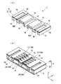
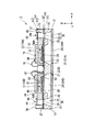
そして、液滴吐出ヘッド1は、図1から図3に示すように、ノズル基板(第2部材)11と、ノズル基板11の上面に設けられた流路形成基板(第1部材)12と、流路形成基板12の上面に設けられて圧電素子13の駆動により変位する振動板14と、振動板14の上面に設けられた封止基板(第1部材)15と、封止基板15上に設けられて圧電素子13を駆動する駆動回路部16とを備えている。
[Droplet ejection head]
The
As shown in FIGS. 1 to 3, the
ノズル基板11は、例えばSUSなどのステンレス鋼で構成されている。そして、ノズル基板11には、貫通孔であってインクの液滴を吐出するノズル開口部(吐出口)21が複数(6個)配列して形成されている。ここで、ノズル開口部21の配列方向は、Y軸方向となっている。そして、配列して形成された複数のノズル開口部21によって、ノズル開口群21A〜21Dが構成されている。ここで、ノズル開口群21A、21BはX軸方向に関して対向配置されており、ノズル開口群21C、21DはX軸方向に関して対向配置されている。また、ノズル開口群21Cはノズル開口群21Aに対して+Y側に形成され、ノズル開口群21Dはノズル開口群21Bに対して+Y側に形成されている。なお、図1では、ノズル開口群21A〜21Dは、それぞれ6個のノズル開口部21によって構成されているように示されているが、実際には例えば720個程度のノズル開口部21によって構成されている。
The
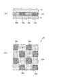
流路形成基板12は、例えばシリコンによって構成されており、異方性エッチングによって複数の貫通孔及びこの貫通孔の側壁から内部に向けてそれぞれ突出する複数の隔壁22が形成されている。この複数の隔壁22は、平面視でほぼ櫛歯状に形成されており、この貫通孔を区画している。また、流路形成基板12の下面には、図4に示すように、ノズル基板11がこの貫通孔の下面側を覆うように接着層23を介して接着されている。
The flow
接着層23は、ノズル基板11との接着領域において分散して複数配置された接着部23aと、複数の接着部23aの間を充填する充填部23bとを備えている。
接着部23aは、例えばエポキシ系の樹脂材料のような高い剛性を有する熱硬化性の接着剤で構成されている。そして、接着部23aは、平面視でほぼ矩形であって、流路形成基板12の接着領域において隣接する他の接着部23aと離間するように島状に分散している。ここで、接着部23aは、引張剪断接着強さが例えば約30MPaであり、硬さが例えばD80であり、20℃における線膨張率が例えば65×10−6/℃となっている。
充填部23bは、例えばアクリル系の樹脂材料のように接着部23aよりも高い弾性及び低い接着力を有する熱硬化性の接着剤で構成されている。そして、充填部23bは、接着部23aの間隙を埋めるように配置されている。ここで、充填部23bは、引張強さが例えば約6MPaであり、硬さが例えばA44であり、20℃における線膨張率が例えば約220×10−6/℃となっている。
The
The
The filling
また、流路形成基板12に形成された貫通孔は、図1から図3に示すように、流路形成基板12とノズル基板11と振動板14とで囲まれることにより複数(6個)の圧力発生室24を形成する。
この圧力発生室24は、ノズル開口群21A〜21Dを構成するノズル開口部21に対応してY軸方向に複数配列して形成されている。そして、ノズル開口群21Aに対応して形成された複数の圧力発生室24によって圧力発生室群24Aが構成され、ノズル開口群21Bに対応して形成された複数の圧力発生室24によって圧力発生室群24Bが形成され、ノズル開口群21Cに対応して形成された複数の圧力発生室24によって圧力発生室群24Cが形成され、ノズル開口群21Dに対応して形成された複数の圧力発生室24によって圧力発生室群24Dが形成される。ここで、圧力発生室群24A、24BはX軸方向に関して対向配置され、圧力発生室群24C、24DはX軸方向に関して対向配置されている。
そして、圧力発生室24の基板外縁部側の端部は、流路形成基板12に形成された貫通孔である供給路25に連通されており、この供給路25を介して流路形成基板12に形成された貫通孔である連通部26により互いに連通されている。
Further, as shown in FIGS. 1 to 3, the through holes formed in the flow
A plurality of the
The end of the
振動板14は、流路形成基板12の上面に設けられた弾性膜27と、弾性膜27の上面に設けられた下電極膜28とを備えている。弾性膜27は、例えば厚さ1〜2μm程度の二酸化シリコンによって形成されている。また、下電極膜28は、例えば厚さ0.2μm程度のPt(白金)などによって形成されている。なお、下電極膜28は、圧電素子13に共通する電極となっている。
The
圧電素子13は、図2及び図3に示すように、下電極膜28の上面に設けられた圧電体膜31と、圧電体膜31の上面に設けられた上電極膜32と、上電極膜32の引出配線であるリード電極33とを備えている。
ここで、圧電体膜31は、例えば厚さ1μm程度の金属酸化物によって構成されている。また、上電極膜32は、例えば厚さ0.1μm程度のPtなどによって構成されている。そして、リード電極33は、例えば厚さ0.1μm程度のAu(金)などによって構成されている。
また、圧電素子13は、複数のノズル開口部21及び圧力発生室24のそれぞれに対応して複数設けられている。すなわち、圧電素子13は、ノズル開口部21ごと(圧力発生室24ごと)に設けられている。そして、上述のように、下電極膜28が複数の圧電素子13の共通電極として機能し、上電極膜32及びリード電極33が複数の圧電素子13の個別電極として機能する。
2 and 3, the
Here, the
A plurality of
そして、ノズル開口群21Aを構成するノズル開口部21と対応してY軸方向に複数並んで設けられた圧電素子13により圧電素子群13Aが形成され、ノズル開口群21Bと対応して設けられた圧電素子13により圧電素子群13Bが形成され、ノズル開口群21Cと対応して設けられた圧電素子13により圧電素子群(図示略)が形成され、ノズル開口群21Dと対応して設けられた圧電素子13により圧電素子群(図示略)が形成される。ここで、圧電素子群13A、13BはX軸方向に関して対向配置され、ノズル開口群21Cと対応する圧電素子群とノズル開口群21Dと対応する圧電素子群とはX軸方向に関して対向配置されている。
なお、圧電素子13は、圧電体膜31、上電極膜32及びリード電極33に加えて下電極膜28を含むものであってもよい。すなわち、本実施形態における下電極膜28は、圧電素子13としての機能と振動板14としての機能とを兼ね備える構成としてもよい。また、本実施形態では、弾性膜27及び下電極膜28によって振動板14が構成されているが、弾性膜27を省略して下電極膜28が弾性膜27の機能を兼ね備える構成としてもよい。
Then, a
The
封止基板15は、図1から図3に示すように、例えば流路形成基板12と同一材料であるシリコン単結晶によって形成されている。また、封止基板15には、連通部26のそれぞれと対応するリザーバ部35がY軸方向に延びるように形成されている。このリザーバ部35と上述した連通部26とによってリザーバ36が構成される。そして、封止基板15には、各連通部26の側壁に接続されて各連通部26にインクを導入する導入路37が形成されている。
また、封止基板15の上面には、コンプライアンス基板(第2部材)41が接合されている。このコンプライアンス基板41は、封止膜42及び固定板43を有しており、封止基板15と上述した接着層23と同様の接着構造により接着されている。
As shown in FIGS. 1 to 3, the sealing
A compliance substrate (second member) 41 is bonded to the upper surface of the sealing
封止膜42は、例えば厚さ6μm程度のポリフェニレンスルフィドフィルムのような剛性が低く可撓性を有する材料によって形成されており、リザーバ部35の上部を封止している。
また、固定板43は、例えば厚さ30μm程度のステンレス鋼のような金属などの硬質の材料によって形成されている。この固定板43のうち、リザーバ部35に対応する領域は、厚さ方向で完全に除去された開口部44となっている。したがって、リザーバ部35の上部は、可撓性を有する封止膜42のみによって封止されているので、内部圧力の変化によって変形可能な可撓部45となっている。また、リザーバ部35の外側のコンプライアンス基板41上には、導入路37に連通してリザーバ部35に機能液を供給するための機能液導入口46が形成されている。
The sealing
The fixing
また、封止基板15のうちX軸方向における中央部には、図2及び図3に示すように、Y軸方向に延びる溝部47が形成されている。この溝部47により、封止基板15は、圧力発生室群24Aに対応する圧電素子群13Aを封止する封止部48Aと、圧力発生室群24Bに対応する圧電素子群13Bを封止する封止部48Bと、圧力発生室群24Cに対応する上記圧電素子群を封止する封止部(図示略)と、圧力発生室群24Dに対応する上記圧電素子群を封止する封止部(図示略)とに分けられる。
すなわち、封止基板15のうち、圧電素子13と対向する領域には、圧電素子13の運動を阻害しない程度の空間を確保した状態で、その空間を密封可能な圧電素子保持部49が形成されている。圧電素子保持部49は、圧電素子群13A、13Bなどの各圧電素子群を覆う大きさで形成されている。また、圧電素子13のうち、少なくとも圧電体膜31は、この圧電素子保持部49内に密封されている。
圧電素子保持部49によって封止されている圧電素子13のうち、リード電極33の基板中央部側の端部は、溝部47において露出した流路形成基板12上に配置されている。ここで、このように溝部47において露出した流路形成基板12上に位置するリード電極33の一部が圧電素子13の電気的接続部となっている。
Further, as shown in FIGS. 2 and 3, a
That is, in the sealing
Of the
駆動回路部16は、それぞれ封止基板15の上に圧電素子群13A、13Bなどの各圧電素子群と対応して配設されている。この駆動回路部16は、例えば回路基板または駆動回路を含む半導体集積回路(IC)を有している。また、駆動回路部16は、液滴吐出ヘッド1の外部に設けられた外部コントローラ(図示略)と電気的に接続されており、液滴吐出ヘッド1がこの外部コントローラによって制御される。
そして、駆動回路部16は、溝部47において露出しているリード電極33とワイヤ51によって接続されている。なお、圧電素子13の上電極膜32とワイヤ51とがリード電極33を介して接続されているが、リード電極33を設けずに上電極膜32を溝部47において露出させてワイヤ51と接続する構成としてもよい。
The
The
[液滴吐出ヘッドの製造方法]
次に、以上のような構成の液滴吐出ヘッド1の製造方法について説明する。なお、本実施形態では、ノズル基板11と流路形成基板12との接着工程や封止基板15とコンプライアンス基板41との接着工程に特徴があるため、この点を中心に説明する。
まず、流路形成基板12及び弾性膜27を形成する。ここでは、流路形成基板12を構成するシリコン基板に熱酸化処理を施すことで、SiO2で構成された弾性膜27を形成する。そして、弾性膜27上に下電極膜28を設けて振動板14を形成し、振動板14上に圧電素子13を形成する。続いて、流路形成基板12を構成するシリコン基板にエッチング処理を施すことで、圧力発生室24、供給路25及び連通部26を形成する。
[Method of manufacturing droplet discharge head]
Next, a method for manufacturing the
First, the flow
次に、流路形成基板12とノズル基板11とを接着層23により接着する接着工程を行う。ここでは、例えば液滴吐出法(インクジェット法)などを用いて流路形成基板12の表面のうちノズル基板11との接着領域に複数の接着部23aを島状に分散して配置する。そして、例えば液滴吐出法などを用いて島状に配置された接着部23aの間を充填部23bで充填する。その後、ノズル基板11の接着領域を接着層23に当接させ、加熱処理を施して接着部23a及び充填部23bを加熱硬化し、流路形成基板12とノズル基板11とを接着させる。このとき、ノズル基板11と流路形成基板12との間の熱膨張係数の違いによって接着部23aに応力が発生するが、接着部23aが島状に分散配置されているので、この応力が緩和される。また、充填部23bが各接着部23a間を充填するので、ノズル基板11と流路形成基板12とが接着層23により封止性よく接着される。以上のようにして、圧電素子13が設けられた流路形成基板12を形成する。
Next, a bonding process is performed in which the flow
一方、流路形成基板12とは別に、封止基板15を構成するシリコン基板にエッチング処理を施すことで、リザーバ部35や溝部47、圧電素子保持部49を形成する。次に、封止基板15とコンプライアンス基板41とを、上述した接着工程と同様の方法により接着層23で接着する。以上のようにして、コンプライアンス基板41が接着された封止基板15を形成する。その後、流路形成基板12と封止基板15とを接合し、封止基板15上に駆動回路部16を実装する。以上のようにして、液滴吐出ヘッド1を製造する。
On the other hand, the
[液滴吐出ヘッドの動作]
このような構成の液滴吐出ヘッド1によりインクの液滴を吐出するには、上述した外部コントローラによって外部に設けられて機能液導入口46に接続された機能液供給装置(図示略)を駆動する。そして、上記機能液供給装置から送出された機能液は、機能液導入口46を介してリザーバ36に供給されて後、ノズル開口部21に至るまでの液滴吐出ヘッド1の内部流路を満たす。
また、上記外部コントローラは、封止基板15上に実装された駆動回路部16などに、例えば駆動電力や指令信号を送信する。そして、指令信号を受信した駆動回路部16は、上記外部コントローラからの指令に基づく駆動信号を各圧電素子13に送信する。これにより、圧力発生室24に対応するそれぞれの下電極膜28及び上電極膜32の間に電圧が印加され、弾性膜27、下電極膜28及び圧電体膜31に変位が生じ、この変位によって各圧力発生室24の容積が変化して内部圧力が高まり、ノズル開口部21から液滴が吐出される。
[Operation of droplet discharge head]
In order to eject ink droplets by the
Further, the external controller transmits, for example, drive power and a command signal to the
[液滴吐出装置]
以上のような液滴吐出ヘッド1は、図5に示すような液滴吐出装置100に設けられる。この液滴吐出装置100は、液滴吐出ヘッド1を備えるインクジェット式記録装置である。
液滴吐出ヘッド1は、インクカートリッジなどと連通するインク流路を具備する記録ヘッドユニットの一部を構成しており、液滴吐出装置100に搭載されている。液滴吐出ヘッドを有する記録ヘッドユニット101、102には、インク供給手段を構成するカートリッジ103、104が着脱可能に設けられている。そして、この記録ヘッドユニット101、102を搭載したキャリッジ105が装置本体106に取り付けられたキャリッジ軸107に軸方向で移動自在に取り付けられている。
[Droplet discharge device]
The
The
記録ヘッドユニット101、102は、例えば、それぞれブラックインク組成物及びカラーインク組成物を吐出するものとしている。そして、駆動モータ108の駆動力が複数の歯車(図示略)及びタイミングベルト109を介してキャリッジ105に伝達されることで、記録ヘッドユニット101、102を搭載したキャリッジ105がキャリッジ軸107に沿って移動するようになっている。一方、装置本体106には、キャリッジ軸107に沿ってプラテン110が設けられており、給紙ローラ(図示略)などにより給紙された紙などの記録媒体である記録シート111がプラテン110上に搬送されるようになっている。
For example, the
以上のような構成の接続構造及び接着方法並びに液滴吐出ヘッド1及び液滴吐出ヘッド1の製造方法によれば、接着部23aを分散配置して接着界面において発生する応力を緩和し、ノズル基板11と流路形成基板12との間や封止基板15とコンプライアンス基板41との間における接着信頼性や耐久性の向上が図れる。そして、接着界面における応力の発生を軽減することで、接着部23aを構成する接着剤の接着力を有効に利用できる。
また、接着部23aの間を接着部23aよりも弾性の高い充填部23bで充填することで、接着層23による封止性の向上が図れる。
さらに、接着部23aを島状に配置して各接着部23aの周囲の長さを短くすることで、各接着部23aにおける応力の発生がより確実に抑制される。
According to the connection structure and the bonding method having the above-described configuration, and the
Further, by filling the space between the
Further, by arranging the
なお、本発明は上記実施形態に限定されるものではなく、本発明の趣旨を逸脱しない範囲において種々の変更を加えることが可能である。
例えば、接着部が平面視でほぼ矩形状となっているが、隣接する接着部同士が離間していれば、他の形状であってもよい。また、接着部が島状に配置されているが、接着部において発生する応力を抑制できれば、ストライプ状など他の形状であってもよい。
また、流路形成基板に接着部及び充填部を配置した後にノズル基板と接着させているが、ノズル基板に接着部及び充填部を配置した後に流路形成基板を接着させてもよい。
そして、接着層が充填部を有しているが、十分な封止性を得ることができれば、充填部を有さない構成としてもよい。
さらに、液滴吐出ヘッドに本発明の接着構造を適用しているが、他の部材に本発明の接着構造を適用してもよい。
In addition, this invention is not limited to the said embodiment, A various change can be added in the range which does not deviate from the meaning of this invention.
For example, the bonding portion is substantially rectangular in a plan view, but may have another shape as long as adjacent bonding portions are separated from each other. Moreover, although the adhesion part is arrange | positioned at island shape, as long as the stress which generate | occur | produces in an adhesion part can be suppressed, other shapes, such as stripe shape, may be sufficient.
In addition, although the adhesive portion and the filling portion are disposed on the flow path forming substrate and then adhered to the nozzle substrate, the flow passage forming substrate may be adhered after the adhesive portion and the filling portion are disposed on the nozzle substrate.
And although the contact bonding layer has a filling part, it is good also as a structure which does not have a filling part, if sufficient sealing performance can be acquired.
Furthermore, although the adhesive structure of the present invention is applied to the droplet discharge head, the adhesive structure of the present invention may be applied to other members.
1 液滴吐出ヘッド、11 ノズル基板(第2部材)、12 流路形成基板(第1部材)、15 封止基板(第1部材)、21 ノズル開口部(吐出口)、23 接着層、23a 接着部、23b 充填部、41 コンプライアンス基板(第2部材)
DESCRIPTION OF
Claims (6)
前記接着層が、前記第1部材の接着領域に分散して配置された複数の接着部を有することを特徴とする接着構造。 An adhesive structure having first and second members bonded together via an adhesive layer,
The adhesive structure, wherein the adhesive layer has a plurality of adhesive portions arranged in a dispersed manner in the adhesive region of the first member.
前記第1部材の接着領域に複数の接着部を分散して配置する工程を有することを特徴とする接着方法。 An adhesion method in which the first and second members are bonded together with an adhesive layer,
A bonding method comprising a step of dispersing and arranging a plurality of bonding portions in the bonding region of the first member.
請求項1から3のいずれか1項に記載の接着構造を備えることを特徴とする液滴吐出ヘッド。 A droplet discharge head having a discharge port for discharging a liquid material,
A droplet discharge head comprising the adhesive structure according to claim 1.
請求項4に記載の接着方法を用いた接着工程を備えることを特徴とする液滴吐出ヘッドの製造方法。 A method of manufacturing a droplet discharge head having a discharge port for discharging a liquid material,
A method for manufacturing a droplet discharge head, comprising a bonding step using the bonding method according to claim 4.
Priority Applications (1)
| Application Number | Priority Date | Filing Date | Title |
|---|---|---|---|
| JP2007023438A JP2008189727A (en) | 2007-02-01 | 2007-02-01 | Bonded structure, bonding method, liquid droplet discharge head and method for producing liquid droplet discharge head |
Applications Claiming Priority (1)
| Application Number | Priority Date | Filing Date | Title |
|---|---|---|---|
| JP2007023438A JP2008189727A (en) | 2007-02-01 | 2007-02-01 | Bonded structure, bonding method, liquid droplet discharge head and method for producing liquid droplet discharge head |
Publications (1)
| Publication Number | Publication Date |
|---|---|
| JP2008189727A true JP2008189727A (en) | 2008-08-21 |
Family
ID=39750139
Family Applications (1)
| Application Number | Title | Priority Date | Filing Date |
|---|---|---|---|
| JP2007023438A Withdrawn JP2008189727A (en) | 2007-02-01 | 2007-02-01 | Bonded structure, bonding method, liquid droplet discharge head and method for producing liquid droplet discharge head |
Country Status (1)
| Country | Link |
|---|---|
| JP (1) | JP2008189727A (en) |
Cited By (2)
| Publication number | Priority date | Publication date | Assignee | Title |
|---|---|---|---|---|
| JP2012076436A (en) * | 2010-10-06 | 2012-04-19 | Seiko Epson Corp | Liquid jet head and liquid jet apparatus |
| EP3482916A1 (en) * | 2017-11-09 | 2019-05-15 | SII Printek Inc | Liquid jet head, method of manufacturing same, and liquid jet recording device |
-
2007
- 2007-02-01 JP JP2007023438A patent/JP2008189727A/en not_active Withdrawn
Cited By (2)
| Publication number | Priority date | Publication date | Assignee | Title |
|---|---|---|---|---|
| JP2012076436A (en) * | 2010-10-06 | 2012-04-19 | Seiko Epson Corp | Liquid jet head and liquid jet apparatus |
| EP3482916A1 (en) * | 2017-11-09 | 2019-05-15 | SII Printek Inc | Liquid jet head, method of manufacturing same, and liquid jet recording device |
Similar Documents
| Publication | Publication Date | Title |
|---|---|---|
| JP2011025493A (en) | Liquid ejection head, method for manufacturing the same, and liquid ejection device | |
| JP2009143002A (en) | Liquid jet head and liquid jet apparatus | |
| JP2011136462A (en) | Liquid droplet ejecting head and liquid droplet ejecting device | |
| JP4614070B2 (en) | Liquid ejecting head and liquid ejecting apparatus | |
| US8444256B2 (en) | Piezoelectric actuator and liquid ejecting head | |
| JP6024492B2 (en) | Liquid ejecting head, liquid ejecting apparatus, and method of manufacturing liquid ejecting head | |
| JP2017177335A (en) | Liquid injection head, liquid injection head unit, liquid injection device, and manufacturing method for liquid injection head unit | |
| JP6060712B2 (en) | Flow path component, liquid ejecting head, liquid ejecting apparatus, and flow path component manufacturing method | |
| TWI243100B (en) | Ink jet print head | |
| JP5621683B2 (en) | Liquid ejecting head and liquid ejecting apparatus | |
| JP2008189727A (en) | Bonded structure, bonding method, liquid droplet discharge head and method for producing liquid droplet discharge head | |
| JP4735740B2 (en) | Liquid ejecting head and liquid ejecting apparatus | |
| JP2006218776A (en) | Liquid injection head and liquid injection apparatus | |
| JP4737389B2 (en) | Liquid ejecting head and liquid ejecting apparatus | |
| JP4930673B2 (en) | Liquid ejecting head and liquid ejecting apparatus | |
| JP2012218251A (en) | Liquid jet head, and liquid jet apparatus | |
| JP2012206281A (en) | Liquid ejecting head and liquid ejecting apparatus | |
| JP2011189585A (en) | Liquid jet head, method of manufacturing liquid jet head, liquid jet head unit and liquid jet apparatus | |
| JP4556416B2 (en) | Method for manufacturing liquid jet head | |
| JP2011206919A (en) | Liquid ejection head and liquid ejection device | |
| JP2013146885A (en) | Liquid ejection head, liquid ejection device, and method of manufacturing liquid ejection head | |
| JP6108060B2 (en) | Liquid ejecting head and liquid ejecting apparatus | |
| JP2008188869A (en) | Bonding method and manufacturing method of liquid droplet discharge head | |
| JP2009220461A (en) | Liquid jet head, its manufacturing method and liquid jet apparatus | |
| JP2009034862A (en) | Liquid jetting head unit and liquid jetting apparatus |
Legal Events
| Date | Code | Title | Description |
|---|---|---|---|
| A300 | Withdrawal of application because of no request for examination |
Free format text: JAPANESE INTERMEDIATE CODE: A300 Effective date: 20100406 |