JP2008181767A - Battery lid structure of electronic equipment - Google Patents
Battery lid structure of electronic equipment Download PDFInfo
- Publication number
- JP2008181767A JP2008181767A JP2007014385A JP2007014385A JP2008181767A JP 2008181767 A JP2008181767 A JP 2008181767A JP 2007014385 A JP2007014385 A JP 2007014385A JP 2007014385 A JP2007014385 A JP 2007014385A JP 2008181767 A JP2008181767 A JP 2008181767A
- Authority
- JP
- Japan
- Prior art keywords
- battery lid
- elongated hole
- battery
- engagement
- lock lever
- Prior art date
- Legal status (The legal status is an assumption and is not a legal conclusion. Google has not performed a legal analysis and makes no representation as to the accuracy of the status listed.)
- Pending
Links
- 238000012856 packing Methods 0.000 description 15
- 238000003780 insertion Methods 0.000 description 10
- 230000037431 insertion Effects 0.000 description 10
- 210000000078 claw Anatomy 0.000 description 6
- 239000011347 resin Substances 0.000 description 6
- 229920005989 resin Polymers 0.000 description 6
- 239000002184 metal Substances 0.000 description 3
- 238000005452 bending Methods 0.000 description 2
- 230000003014 reinforcing effect Effects 0.000 description 2
- 230000002093 peripheral effect Effects 0.000 description 1
- 229910001220 stainless steel Inorganic materials 0.000 description 1
- 239000010935 stainless steel Substances 0.000 description 1
Images
Classifications
-
- H—ELECTRICITY
- H01—ELECTRIC ELEMENTS
- H01M—PROCESSES OR MEANS, e.g. BATTERIES, FOR THE DIRECT CONVERSION OF CHEMICAL ENERGY INTO ELECTRICAL ENERGY
- H01M50/00—Constructional details or processes of manufacture of the non-active parts of electrochemical cells other than fuel cells, e.g. hybrid cells
- H01M50/20—Mountings; Secondary casings or frames; Racks, modules or packs; Suspension devices; Shock absorbers; Transport or carrying devices; Holders
- H01M50/204—Racks, modules or packs for multiple batteries or multiple cells
- H01M50/207—Racks, modules or packs for multiple batteries or multiple cells characterised by their shape
- H01M50/213—Racks, modules or packs for multiple batteries or multiple cells characterised by their shape adapted for cells having curved cross-section, e.g. round or elliptic
-
- H—ELECTRICITY
- H01—ELECTRIC ELEMENTS
- H01M—PROCESSES OR MEANS, e.g. BATTERIES, FOR THE DIRECT CONVERSION OF CHEMICAL ENERGY INTO ELECTRICAL ENERGY
- H01M50/00—Constructional details or processes of manufacture of the non-active parts of electrochemical cells other than fuel cells, e.g. hybrid cells
- H01M50/20—Mountings; Secondary casings or frames; Racks, modules or packs; Suspension devices; Shock absorbers; Transport or carrying devices; Holders
- H01M50/262—Mountings; Secondary casings or frames; Racks, modules or packs; Suspension devices; Shock absorbers; Transport or carrying devices; Holders with fastening means, e.g. locks
-
- H—ELECTRICITY
- H01—ELECTRIC ELEMENTS
- H01M—PROCESSES OR MEANS, e.g. BATTERIES, FOR THE DIRECT CONVERSION OF CHEMICAL ENERGY INTO ELECTRICAL ENERGY
- H01M50/00—Constructional details or processes of manufacture of the non-active parts of electrochemical cells other than fuel cells, e.g. hybrid cells
- H01M50/20—Mountings; Secondary casings or frames; Racks, modules or packs; Suspension devices; Shock absorbers; Transport or carrying devices; Holders
- H01M50/271—Lids or covers for the racks or secondary casings
-
- Y—GENERAL TAGGING OF NEW TECHNOLOGICAL DEVELOPMENTS; GENERAL TAGGING OF CROSS-SECTIONAL TECHNOLOGIES SPANNING OVER SEVERAL SECTIONS OF THE IPC; TECHNICAL SUBJECTS COVERED BY FORMER USPC CROSS-REFERENCE ART COLLECTIONS [XRACs] AND DIGESTS
- Y02—TECHNOLOGIES OR APPLICATIONS FOR MITIGATION OR ADAPTATION AGAINST CLIMATE CHANGE
- Y02E—REDUCTION OF GREENHOUSE GAS [GHG] EMISSIONS, RELATED TO ENERGY GENERATION, TRANSMISSION OR DISTRIBUTION
- Y02E60/00—Enabling technologies; Technologies with a potential or indirect contribution to GHG emissions mitigation
- Y02E60/10—Energy storage using batteries
Landscapes
- Chemical & Material Sciences (AREA)
- Chemical Kinetics & Catalysis (AREA)
- Electrochemistry (AREA)
- General Chemical & Material Sciences (AREA)
- Battery Mounting, Suspending (AREA)
- Connection Of Batteries Or Terminals (AREA)
Abstract
Description
本発明は、電子機器の内部に設けられた電池ケースを開閉する電池蓋の構造に関する。 The present invention relates to a structure of a battery lid that opens and closes a battery case provided inside an electronic device.
従来、電子機器の内部に設けられた電池ケースを開閉する電池蓋に関して、各種の構造が提案されている。例えば、特許文献1には、カメラの電池蓋の構造として、ヒンジピンによりカメラ本体に対して回動自在に支持されるヒンジ板と、該ヒンジ板の外側に該ヒンジ板に対してスライド自在に取り付けられた電池蓋体とを備え、電池蓋体に、電池蓋の閉止位置にて電池蓋体をヒンジピン側へスライド移動させることでカメラカバーの係止孔に係止する係止爪を設けた構造の電池蓋が開示されている。
上記した従来の電池蓋構造には、電池蓋体に、電池蓋の閉止位置にて電池蓋体をヒンジピン側へスライド移動させることでカメラカバーの係止孔に係止する係止爪が設けられているのみであり、電池蓋が閉止した状態において、電池蓋体のスライド動作を阻止する手段がない。 In the conventional battery lid structure described above, the battery lid body is provided with a locking claw that is locked to the locking hole of the camera cover by sliding the battery lid body to the hinge pin side at the battery lid closing position. However, there is no means for preventing the sliding operation of the battery lid when the battery lid is closed.
そこで、上記した従来の電池蓋の構造に対して、電池蓋体に、電池蓋体のスライド方向に垂直な方向にスライドするロックレバー部、およびロックレバー部のスライド動作に連動して電池蓋体のスライド方向に垂直な方向にスライドする係合部を設けるとともに、ヒンジ板に前記係合部が係合する平面視L字形状の係合長穴を設けて、電池蓋が閉止した状態において、前記係合長穴の電池蓋体のスライド方向に垂直な方向の部分に前記係合部を係合させることで、電池蓋体のスライド動作を阻止し、電池蓋をスライドさせるときには、前記係合長穴の電池蓋体のスライド方向に平行な方向の部分に前記係合部を係合させる構成を別途付加することが考えられる。 Therefore, with respect to the structure of the conventional battery lid described above, the battery lid body is slid in a direction perpendicular to the sliding direction of the battery lid body, and the battery lid body is interlocked with the sliding operation of the lock lever section. In a state where the battery lid is closed by providing an engaging portion that slides in a direction perpendicular to the sliding direction of the above, and providing an L-shaped engaging elongated hole in a plan view for engaging the engaging portion on the hinge plate, When the engagement portion is engaged with a portion of the engagement elongated hole that is perpendicular to the sliding direction of the battery lid body, the battery lid body is prevented from sliding, and the battery lid is slid. It is conceivable to separately add a configuration in which the engaging portion is engaged with a portion of the elongated hole in the direction parallel to the sliding direction of the battery lid.
しかしながら、電池蓋の剛性を確保するためにヒンジ板は金属製であり、そのため前記係合長穴の端面は粗く、前記係合部が前記係合長穴をスライドする際の摺動抵抗が大きくなり、係合部の摩耗や、摩擦によるスライド動作阻害の問題が起こる。 However, in order to ensure the rigidity of the battery cover, the hinge plate is made of metal, so that the end face of the engagement elongated hole is rough, and the sliding resistance when the engagement portion slides through the engagement elongated hole is large. Thus, there is a problem that the sliding of the engaging portion or the sliding operation is hindered due to friction.
本発明は、上記問題点に鑑み、係合長穴をスライドする係合部の摩耗や、摩擦によるスライド動作阻害を回避できる電子機器の電池蓋構造を提供することを目的とする。 In view of the above problems, an object of the present invention is to provide a battery lid structure for an electronic device that can avoid wear of an engaging portion that slides through an engaging long hole and obstruction of sliding operation due to friction.
本発明の電子機器の電池蓋構造は、電子機器に対して回動自在に軸支される回動板と、前記回動板の外側に、前記回動板の回動軸に垂直な方向にスライド自在に装着された電池蓋体と、前記電池蓋体の外側に、前記回動板の回動軸に平行な方向にスライド自在に取り付けられたロックレバー部と、前記回動板に形成された係合長穴と、前記電池蓋体の内側に取り付けられ、前記係合長穴に係合し、前記ロックレバー部のスライド動作に連動して前記回動板の回動軸に平行な方向にスライドする係合部と、を備え、前記電子機器の内部に設けられた電池ケースを開閉する電池蓋の構造であって、前記係合長穴は、前記回動板の回動軸に垂直な方向に長い第1長穴と、回動軸に平行な方向に長く且つ第1端部が前記第1長穴の回動軸側の端部と結合して前記第1長穴に連続する第2長穴と、からなり、前記回動板は、その外側に、前記電池蓋体のスライド動作時に前記電池蓋体の一部に係合して、前記回動板の回動軸側の第1位置および回動軸とは反対側の第2位置にて前記電池蓋体を係止する板ばね体を備え、前記板ばね体は、その一部として一体形成された前記係合長穴の壁面の一部または全部を覆う滑り面部を備え、前記電池蓋体は、前記ロックレバー部を前記第2長穴の第1端部とは反対側の第2端部側へ付勢する付勢部材を備え、前記係合部は、前記滑り面部により覆われた前記係合長穴に係合し、前記電池蓋体が前記第1位置にあるとき、前記第2長穴に係合して前記電池蓋体のスライド動作を阻止し、前記ロックレバー部が前記第2長穴の第1端部側へスライド移動すると、前記第2長穴との係合から解放され、前記電池蓋体のスライド動作時には、前記第1長穴に係合することを特徴とする。 The battery lid structure of the electronic device according to the present invention includes a rotating plate that is pivotally supported with respect to the electronic device, an outer side of the rotating plate, and a direction perpendicular to the rotating shaft of the rotating plate. A battery lid that is slidably mounted, a lock lever portion that is slidably attached to the outside of the battery lid in a direction parallel to the rotation axis of the rotation plate, and the rotation plate. The engagement elongated hole is attached to the inside of the battery cover body, is engaged with the engagement elongated hole, and is parallel to the rotation axis of the rotation plate in conjunction with the sliding operation of the lock lever portion. A battery lid for opening and closing a battery case provided inside the electronic device, wherein the engagement elongated hole is perpendicular to a rotation axis of the rotation plate. A first elongated hole that is long in a direction, and a first end that is long in a direction parallel to the rotation axis and the end on the rotation axis side of the first elongated hole. And the second elongated hole continuing to the first elongated hole, and the rotating plate is engaged with a part of the battery lid body at the time of sliding operation of the battery lid body, The leaf spring body includes a leaf spring body that locks the battery lid body at a first position on the pivot shaft side of the pivot plate and a second position on the opposite side of the pivot shaft, and the leaf spring body is a part of the leaf spring body. A sliding surface portion covering a part or all of the wall surface of the engagement elongated hole formed integrally as the battery lid, wherein the battery cover body has the lock lever portion opposite to the first end portion of the second elongated hole. A biasing member that biases toward the second end side, wherein the engagement portion engages with the engagement elongated hole covered by the sliding surface portion, and the battery lid is in the first position; The battery lid is prevented from sliding by engaging with the second elongated hole, and the lock lever portion slides toward the first end of the second elongated hole. The released from engagement with the second slot, wherein at the time of sliding motion of the battery lid, and wherein the engaging said first elongated hole.
本発明によれば、板ばね体に一体形成された滑り面部により係合長穴の壁面を覆うことで、係合長穴の壁面に接しながらスライド移動する係合部の摩耗、破損や、摩擦によるスライド動作阻害を回避できる。また、板ばね体の本来の機能である電池蓋体の係止を兼ねているので新たなパーツを追加せずにすむ。 According to the present invention, the wall surface of the engagement elongated hole is covered with the sliding surface portion integrally formed with the leaf spring body, so that the engagement portion that slides while contacting the wall surface of the engagement elongated hole is worn, damaged, or frictionally. The sliding movement hindrance due to can be avoided. In addition, since it also serves as a latch for the battery lid which is the original function of the leaf spring body, it is not necessary to add new parts.
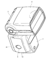
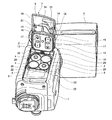
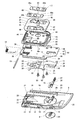
以下、本発明の実施の形態について図面を用いて説明する。本実施の形態では、電子機器の電池蓋の一例として、ストロボ装置の電池蓋の構造について説明する。図1は、本実施の形態におけるストロボ装置の上側からみた斜視図であって、電池蓋が閉止した状態を示す。図2は、本実施の形態におけるストロボ装置の底側からみた斜視図であって、電池蓋を開放した状態を示す。図3は、上記電池蓋の分解斜視図である。 Hereinafter, embodiments of the present invention will be described with reference to the drawings. In this embodiment, a structure of a battery cover of a strobe device will be described as an example of a battery cover of an electronic device. FIG. 1 is a perspective view of the strobe device according to the present embodiment as viewed from above, and shows a state in which a battery cover is closed. FIG. 2 is a perspective view seen from the bottom side of the strobe device according to the present embodiment, and shows a state in which the battery cover is opened. FIG. 3 is an exploded perspective view of the battery lid.
図1、2に示すように、本ストロボ装置は、本体部1と、被写体を照明する発光部2と、発光部2を本体部1に連結する連結部3とからなり、本体部1の内部に、4本の電池4を装填可能な電池ケース5が設けられ、本体部1の右側面に電池ケースの開口凹部6と、その開口凹部6を開閉する電池蓋7が配置される。電池蓋7は、本体部1の右側面の上側(発光部1側)に回動自在に固定されたヒンジピン(不図示)に支持され、電池ケース5を開閉する位置に回動でき、図1に示すように、電池蓋閉止状態のときに電池ケースの開口凹部6に嵌合される。
As shown in FIGS. 1 and 2, the strobe device includes a main body portion 1, a
上記電池蓋7は、図3の分解斜視図に示すように、ロックレバー部8と、電池蓋体9と、ロックレバー受け部10と、板ばね体11と、蓋付勢ばね12と、本体部1に回動自在に固定されるヒンジピン13と、ヒンジピン13により回動自在に支持される押さえ板(回動板)14と、押さえ板14に装着される防水パッキン体15と、防水パッキン体15を介して押さえ板14に装着される端子押さえ板16と、端子押さえ板16に装着される2つの端子17とを有してなり、電池蓋体9は、押さえ板14の外側にスライド自在に装着される。電池蓋体9のスライド方向は、電池蓋7の回動軸、すなわち押さえ板14の回動軸(ヒンジピン13の回動軸)に垂直な方向であり、図1に示す電池蓋閉止状態から電池蓋体9を本体部1の底部側へスライド移動させることで、電池蓋7の開放が可能となる。
As shown in the exploded perspective view of FIG. 3, the battery lid 7 includes a
上記電池蓋体9は、樹脂製であり、図2、3に示すように、ヒンジピン13の回動軸と平行な方向の両端面に、電池ケース5側へ突出するスライドガイド部18を有する。電池蓋体9は、スライドガイド部18を押さえ板14のヒンジピン13の回動軸と平行な方向の両端部に係合させることで、押さえ板14の外側にスライド自在に装着される。
The battery lid body 9 is made of resin, and has
また、このスライドガイド部18の外側にはそれぞれヒンジピン13側が開口する断面L字形状の3つのスライド係合部19が形成されている。一方、電池ケースの開口凹部6の上記スライドガイド部18に対向する両壁面にはそれぞれ3つの被係合部20が形成されており、電池蓋体9が押さえ板14の回動軸側(ヒンジピン13側)の係止位置(第1位置)にあるとき、被係合部20が上記した断面L字形状のスライド係合部19に係合して、電池蓋体9の閉止状態が保持される。また、電池蓋体9を押さえ板14の回動軸とは反対側(本体部1の底部側)の非係止位置(第2位置)へスライド移動させて上記係合を解放すると、蓋付勢ばね12の付勢力により電池蓋7は開放位置へ回動する。
Further, on the outside of the
なお、ここでは、被係合部20は、押さえ板14の回動軸とは反対側(反ヒンジピン側)が開口する断面L字形状をしており、電池蓋体9を反ヒンジピン側へスライド移動させたときに、スライド係合部19の反ヒンジピン側の面が被係合部20のヒンジピン13側の面に当接することで、非係止位置にて電池蓋体9のスライド動作を止めることができる。
Here, the engaged
さらに、電池蓋体9の内側面には断面L字形状の2つの係止爪21が設けられており、電池蓋体9が係止位置にあるとき、電池ケースの開口凹部6内に設けられた2つの被係止部22に係止爪21が係合して、電池蓋体9の閉止状態が保持される。また、電池蓋体9を反ヒンジピン側へスライド移動させると、係止爪21と被係止部22との係合が解放される。
Furthermore, two
また図1に示すように、電池蓋体9の電池ケース5とは反対側の外側面には凹部23が設けられており、この凹部23上に、ロックレバー部8が、電池蓋7の回動軸、すなわち押さえ板14の回動軸(ヒンジピン13の回動軸)に平行な方向に摺動自在に装着される。
As shown in FIG. 1, a
また電池蓋体9の凹部23には、図3に示すように、ロックレバー部8の内側(電池蓋体9側)に設けられた突起部24が挿入されるスライド穴25が形成されている。このスライド穴25は、電池蓋体9のスライド方向に垂直な方向、すなわち電池蓋7の回動軸に平行な方向に長い長穴であり、ロックレバー部8は、その方向にスライド自在である。
Further, as shown in FIG. 3, a
ロックレバー部8は、電池蓋体9が係止位置にあるとき、電池蓋体9の押さえ板14に対するスライド動作を阻止するロック部材であり、本体部1の前面側のロック位置にあるとき、電池蓋体9のスライド動作をロックする。一方、撮影者が手動操作にてロックレバー部8を本体部1の後面側へスライド移動させ、ロックレバー部8を非ロック位置にすると、電池蓋体9のロック状態は解除され、このロック状態が解除されているときに、撮影者は、手動操作にて電池蓋体9を反ヒンジピン側へスライド移動させることができる。
The
また、電池蓋体9の内側面には、図3に示すように、ロックレバー受け部10の突起部26に取り付けられた付勢用つるまきばね(付勢部材)27が嵌合する嵌合部28が形成されている。突起部26は、本体部1の後面側へ突出しており、この突起部26に取り付けられた付勢用つるまきばね27を電池蓋体9の嵌合部28に嵌合させることで、ロックレバー部8は、常時、本体部1の前面側へ付勢される。
Further, as shown in FIG. 3, a fitting spring spring (biasing member) 27 attached to the
また、ロックレバー受け部10には、ロックレバー部8の突起部24が嵌合される穴部が設けられており、電池蓋体9の凹部23にロックレバー部8を配置して、スライド穴25からロックレバー部8の突起部24を突出させて、電池蓋体9の内側面に配置したロックレバー受け部10の穴部に嵌合させることで、ロックレバー部8は、電池蓋体9の凹部23に摺動自在に固定される。同時に、ロックレバー受け部10の突起部26に取り付けられた付勢用つるまきばね27を嵌合部28に嵌合させることで、ロックレバー部8は、常時、本体部1の前面側へ付勢される。この付勢用つるまきばね27の付勢力により、電池蓋体9が上記係止位置にあるとき、ロックレバー部8は上記ロック位置に位置し、電池蓋体9のスライド動作がロックされる。このロック状態を解除するときは、付勢用つるまきばね27の付勢力に抗して手動操作にてロックレバー部8を上記非ロック位置へスライド移動させる。
Further, the lock
またロックレバー受け部10には、押さえ板14側へ突出して、後述する押さえ板14の係合長穴に係合する係合部29が形成されている。この電池蓋体9の内側に取り付けられた係合部29は、電池蓋体9が上記係止位置にあるとき、ロックレバー部8のスライド動作に連動して押さえ板14の回動軸に平行な方向にスライドする。一方、ロックレバー部8が上記非ロック位置にあるときには、電池蓋体9のスライド動作に連動して押さえ板14の回動軸に垂直な方向にスライドする。
The lock
また、電池蓋体9の内側面には、さらに、上記した係止位置と非係止位置において、板ばね体11に設けられたクリック用ばね30が係合する一時係合部31が設けられている。またさらに、電池蓋体9を反ヒンジピン側へスライド移動させたときに、板ばね体11に設けられた蓋止め部32が当接して、非係止位置にてスライド動作を止めるための蓋止め突起部33が設けられている。
Further, the inner surface of the battery lid body 9 is further provided with a
板ばね体11は、その一部として一体形成された上記クリック用ばね30および蓋止め部32を備える。クリック用ばね30は、電池蓋体9を上記した係止位置および非係止位置の各位置に位置決めするための付勢部材であり、電池蓋体9のスライド動作時に上記した一時係合部31に係合して、係止位置および非係止位置にて電池蓋体9を係止する。さらに、板ばね体11は、その一部として一体形成されたトレース部34を備える。トレース部34は、後述する押さえ板14の係合長穴の壁面(端面)の一部または全部を覆う滑り面部として機能する。
The
また、板ばね体11には、板ばね体11を押さえ板14に装着するためのネジ挿通穴35が設けられている。また、板ばね体11には、曲がり防止用のリブ36や、蓋止め部32の補強用の凹部37が形成されている。
The
押さえ板14は、金属板で形成され、例えばステンレス製であり、電池蓋7の剛性を確保している。この押さえ板14は、回動軸側にヒンジピン13が回転自在に嵌入する軸支持部38を備え、本体部1に対して回動自在に軸支される。また、押さえ板14には、その外側に板ばね体11を装着し、内側に防水パッキン体15および端子押さえ板16を装着するためのネジ挿通穴39が設けられている。なお、蓋付勢ばね12は、軸支持部38に挿入されたヒンジピン13により支持される。
The holding
さらに、押さえ板14には、上記したロックレバー受け部10の係合部29が係合する係合長穴40が形成されている。この係合長穴40は、平面視L字状であり、電池蓋体9のスライド方向(押さえ板14の回動軸に垂直な方向)に長い第1長穴41と、電池蓋体9のスライド方向に垂直な方向、すなわちロックレバー部8のスライド方向に平行な方向(押さえ板14の回動軸に平行な方向)に長い第2長穴42からなる。第2長穴42は、その一方の端部(第1端部)が第1長穴41のヒンジピン13側(押さえ板14の回動軸側)の端部と結合して第1長穴41に連続して形成されている。
Further, the holding
ロックレバー受け部10の係合部29は、ロックレバー部8が上記ロック位置にあるとき、第2長穴42の上記一方の端部とは反対側の端部(第2端部)に位置する。一方、ロックレバー部8が上記非ロック位置にあるとき、係合部29は第2長穴42の上記一方の端部(第1端部)に位置する。
The engaging
すなわち、電池蓋体9が係止位置にあるとき、上記した付勢用つるまきばね27の付勢力により、ロックレバー部8は第2長穴42の第2端部側へ付勢されてロック位置に位置し、ロックレバー受け部10の係合部29は第2長穴42の第2端部に位置する。一方、手動操作によりロックレバー部8を第2長穴42の第1端部側へスライド移動させ、ロックレバー部8を上記非ロック位置に位置させたとき、係合部29は第2長穴42の第1端部に位置する。
That is, when the battery cover 9 is in the locking position, the
よって、上記したトレース部34により壁面(端面)の一部または全部が覆われた係合長穴40に係合する係合部29は、電池蓋体9が上記係止位置にあるとき、第2長穴42に係合して電池蓋体9のスライド動作を阻止する。一方、手動操作によりロックレバー部8を上記非ロック位置に位置させると、係合部29は第2長穴42との係合から解放され、電池蓋体9のスライド動作が可能となり、電池蓋体9のスライド動作時には、第1長穴41に係合して、電池蓋体9のスライド動作に連動して押さえ板14の回動軸に垂直な方向にスライドする。
Therefore, when the battery lid body 9 is in the locking position, the engaging
ここで、ロックレバー部8およびロックレバー受け部10は金属製であってもよいが、板ばね体11のトレース部34により係合長穴40の壁面の全部または一部を覆う構成であるので、樹脂製の方が滑りがよくなる。
Here, the
このように板ばね体11に一体形成されたトレース部34により係合長穴40の壁面を覆うことで、係合長穴40の壁面に接しながらスライド移動する樹脂製の係合部29の摩耗、破損を防止できる。さらに、係合部29を係合長穴40の深さ方向に浅く形成することで、ロックレバー受け部10を樹脂製としても破損の心配がより少なくなる。また、電池蓋7を閉止した後、ロックレバー部8が付勢用つるまきばね27によりスムーズにロック位置に戻る。また、板ばね体11の本来の機能(スライド止め、クリック)を兼ねているので新たなパーツを追加せずにすむ。
By covering the wall surface of the engagement elongated
防水パッキン体15は、樹脂製であり、端子押さえ板16が嵌合される凹部43が電池ケース5側に設けられている。この防水パッキン体15の凹部43の外側の壁面は、電池蓋7が閉止位置にあるとき、電池ケース5の内壁面に密着し、水密状態となる。また、防水パッキン体15には、ネジ挿通穴44が設けられている。
The
端子押さえ板16は、樹脂製であり、図2に示すように、防水パッキン体15の凹部43に嵌め込まれる。また、端子押さえ板16には、図示しないが、押さえ板14側(電池ケース5とは反対側)が開口するネジ穴が設けられている。また、電池ケース5側の面には、端子取り付け用の凹部45と、第1突起部46が設けられている。また、電池の逆入れ防止用に、プラス用端子周りに突出する第2突起部47が設けられている。
The
端子17には、接点部48a、48bと、貫通穴49とが設けられている。この端子17は、端子押さえ板16の凹部45に嵌め込まれ、貫通穴49に挿入した第1突起部46にて熱カシメにより端子押さえ板16に固着される。
The terminal 17 is provided with
電池蓋7は、押さえ板14の電池ケース5とは反対側に板ばね体11を配置し、押さえ板14の電池ケース5側に、端子17が固着され、防水パッキン体15の凹部43に嵌めこまれた端子押さえ板16を配置して、板ばね体11のネジ挿通穴35、押さえ板14のネジ挿通穴39、防水パッキン体15のネジ挿通穴44、および端子押さえ板16のネジ穴に、板ばね体11側からネジ50を螺着することで、押さえ板14に板ばね体11、防水パッキン体15、および端子押さえ板16を装着し、この押さえ板14のヒンジピン13の回動軸と平行な方向の両端部と電池蓋体9のスライドガイド部18とを係合させて、組み立てられる。
The battery lid 7 has a
上記組み立て状態の電池蓋7において、電池蓋体9は、押さえ板14に対して、反ヒンジピン側に所定量だけスライド移動が可能となっている。上述のようにして組み立てられた電池蓋7は、ヒンジピン13により電池ケースの開口凹部6の端部に回動自在に取り付けられ、電池ケースの開口凹部6を開閉可能とする。
In the battery lid 7 in the assembled state, the battery lid body 9 can be slid by a predetermined amount toward the anti-hinge pin side with respect to the
電池蓋7が閉止位置にあり、且つ電池蓋体9がヒンジピン13側の係止位置にスライドしているとき、ロックレバー部8は付勢用つるまきばね27の付勢力によりロック位置にあり、ロックレバー受け部10の係合部29が押さえ板14の係合長穴40の第2長穴42に係合しているので、電池蓋体9のスライド動作がロックされ、電池蓋7は閉止位置にロックされる。
When the battery cover 7 is in the closed position and the battery cover body 9 is slid to the locking position on the
また、電池蓋7を閉めるときには、防水パッキン体15の凹部43の外周部(リブ)を電池ケース5内周に内嵌させるために、指圧にて電池蓋7を押圧し所定緊迫力にて密着させる。このように防水パッキン体15を電池ケース5内に嵌入して密着させることで、電池ケース5は、水密状態に保たれる。また、装填されている電池4は、図示しない付勢部材により開口側方向に付勢されており、4本の電池4の電極は、端子17と接触する。
Further, when the battery cover 7 is closed, the battery cover 7 is pressed with finger pressure and closely contacted with a predetermined tightening force so that the outer peripheral portion (rib) of the
電池ケース5を開放する場合は、一旦、ロックレバー部8を非ロック位置にスライドさせて、ロックレバー受け部10の係合部29を押さえ板14の係合長穴40の第2長穴42から外した後、電池蓋体9を反ヒンジピン側の非係止位置へスライドさせる。この反ヒンジピン側へのスライド移動時には、板ばね体11のクリック用ばね30が電池蓋体9の一時係合部31に係合して、電池蓋体9は非係止位置でクリック保持され、同時に板ばね体11の蓋止め部32が電池蓋体9の蓋止め突起部33に当たるとともに、電池蓋体9のスライド係合部19の反ヒンジピン側の面が電池ケースの開口凹部6の被係合部20のヒンジピン13側の面に当たり、それ以上、スライド移動できない。
When opening the battery case 5, the
本発明にかかる電子機器の電池蓋構造は、電池蓋が閉止した状態において電池蓋体をスライド移動させることで電池ケースの開放を可能にする電池蓋に対して、電池蓋閉止時に電池蓋体のスライド移動を阻止するための係合長穴および、その係合長穴に係合してスライドする係合部を設けた構造において、係合長穴をスライドする係合部の摩耗や、摩擦によるスライド動作阻害を回避でき、電池等のケースの蓋として有用である。 The battery lid structure of the electronic device according to the present invention is such that the battery lid can be opened by sliding the battery lid in a state where the battery lid is closed, while the battery lid is closed when the battery lid is closed. In a structure provided with an engagement slot for preventing sliding movement and an engagement section that engages and slides in the engagement slot, wear of the engagement section that slides through the engagement slot or friction It is possible to avoid the hindrance to the sliding operation and is useful as a lid for cases such as batteries.
1 本体部
2 発光部
3 連結部
4 電池
5 電池ケース
6 電池ケースの開口凹部
7 電池蓋
8 ロックレバー部
9 電池蓋体
10 ロックレバー受け部
11 板ばね体
12 蓋付勢ばね
13 ヒンジピン
14 押さえ板
15 防水パッキン体
16 端子押さえ板
17 端子
18 スライドガイド部
19 スライド係合部
20 被係合部
21 係止爪
22 被係止部
23 電池蓋体の凹部
24 ロックレバー部の突起部
25 スライド穴
26 ロックレバー受け部の突起部
27 付勢用つるまきばね
28 嵌合部
29 係合部
30 クリック用ばね
31 一時係合部
32 蓋止め部
33 蓋止め突起部
34 トレース部
35 板ばね体のネジ挿通穴
36 板ばね体の曲がり防止用のリブ
37 板ばね体の蓋止め部の補強用凹部
38 軸支持部
39 押さえ板のネジ挿通穴
40 係合長穴
41 第1長穴
42 第2長穴
43 防水パッキン体の凹部
44 防水パッキン体のネジ挿通穴
45 端子押さえ板の凹部
46 端子押さえ板の第1突起部
47 端子押さえ板の第2突起部
48a、48b 接点部
49 貫通穴
50 ネジ
DESCRIPTION OF SYMBOLS 1 Main-
Claims (1)
前記係合長穴は、前記回動板の回動軸に垂直な方向に長い第1長穴と、回動軸に平行な方向に長く且つ第1端部が前記第1長穴の回動軸側の端部と結合して前記第1長穴に連続する第2長穴と、からなり、
前記回動板は、その外側に、前記電池蓋体のスライド動作時に前記電池蓋体の一部に係合して、前記回動板の回動軸側の第1位置および回動軸とは反対側の第2位置にて前記電池蓋体を係止する板ばね体を備え、
前記板ばね体は、その一部として一体形成された前記係合長穴の壁面の一部または全部を覆う滑り面部を備え、
前記電池蓋体は、前記ロックレバー部を前記第2長穴の第1端部とは反対側の第2端部側へ付勢する付勢部材を備え、
前記係合部は、前記滑り面部により覆われた前記係合長穴に係合し、前記電池蓋体が前記第1位置にあるとき、前記第2長穴に係合して前記電池蓋体のスライド動作を阻止し、前記ロックレバー部が前記第2長穴の第1端部側へスライド移動すると、前記第2長穴との係合から解放され、前記電池蓋体のスライド動作時には、前記第1長穴に係合する
ことを特徴とする電子機器の電池蓋構造。 A rotating plate that is pivotally supported with respect to the electronic device, and a battery lid that is slidably mounted on the outside of the rotating plate in a direction perpendicular to the rotating shaft of the rotating plate; A lock lever portion slidably attached to the outside of the battery lid body in a direction parallel to the rotation axis of the rotary plate, an engagement slot formed in the rotary plate, and the battery lid body An engagement portion that is attached to the inside of the engagement plate, engages with the engagement elongated hole, and slides in a direction parallel to the rotation axis of the rotation plate in conjunction with the slide operation of the lock lever portion, A battery lid structure for opening and closing a battery case provided inside the electronic device,
The engagement elongated hole is a first elongated hole that is long in a direction perpendicular to the rotation axis of the rotation plate, and is long in a direction parallel to the rotation axis, and the first end portion is a rotation of the first elongated hole. A second elongated hole connected to the end on the shaft side and continuing to the first elongated hole;
The rotating plate is engaged with a part of the battery lid body at the time of sliding operation of the battery lid body, and the first position and the rotating shaft on the rotating shaft side of the rotating plate are outside. A leaf spring body for locking the battery lid body at the second position on the opposite side;
The leaf spring body includes a sliding surface portion that covers part or all of the wall surface of the engagement elongated hole integrally formed as a part thereof,
The battery lid includes a biasing member that biases the lock lever portion to a second end side opposite to the first end of the second elongated hole,
The engagement portion engages with the engagement elongated hole covered by the sliding surface portion, and engages with the second elongated hole when the battery lid body is in the first position, so that the battery lid body is engaged. When the lock lever portion slides toward the first end side of the second elongated hole, the engagement with the second elongated hole is released, and during the sliding operation of the battery lid, A battery lid structure for an electronic device, wherein the battery lid structure is engaged with the first elongated hole.
Priority Applications (4)
| Application Number | Priority Date | Filing Date | Title |
|---|---|---|---|
| JP2007014385A JP2008181767A (en) | 2007-01-25 | 2007-01-25 | Battery lid structure of electronic equipment |
| PCT/JP2008/050177 WO2008090766A1 (en) | 2007-01-25 | 2008-01-10 | Battery lid structure for electronic device |
| CN2008800026521A CN101584060B (en) | 2007-01-25 | 2008-01-10 | Battery lid structure for electronic device |
| US12/523,325 US8241783B2 (en) | 2007-01-25 | 2008-01-10 | Battery lid structure for electronic device |
Applications Claiming Priority (1)
| Application Number | Priority Date | Filing Date | Title |
|---|---|---|---|
| JP2007014385A JP2008181767A (en) | 2007-01-25 | 2007-01-25 | Battery lid structure of electronic equipment |
Publications (2)
| Publication Number | Publication Date |
|---|---|
| JP2008181767A true JP2008181767A (en) | 2008-08-07 |
| JP2008181767A5 JP2008181767A5 (en) | 2010-02-25 |
Family
ID=39644341
Family Applications (1)
| Application Number | Title | Priority Date | Filing Date |
|---|---|---|---|
| JP2007014385A Pending JP2008181767A (en) | 2007-01-25 | 2007-01-25 | Battery lid structure of electronic equipment |
Country Status (4)
| Country | Link |
|---|---|
| US (1) | US8241783B2 (en) |
| JP (1) | JP2008181767A (en) |
| CN (1) | CN101584060B (en) |
| WO (1) | WO2008090766A1 (en) |
Cited By (5)
| Publication number | Priority date | Publication date | Assignee | Title |
|---|---|---|---|---|
| JP2012018771A (en) * | 2010-07-06 | 2012-01-26 | Panasonic Corp | Electronic apparatus |
| TWI383530B (en) * | 2009-06-05 | 2013-01-21 | Hon Hai Prec Ind Co Ltd | Battery cover |
| JP2014150097A (en) * | 2013-01-31 | 2014-08-21 | Xacti Corp | Electronic apparatus with lid |
| JP2016096268A (en) * | 2014-11-14 | 2016-05-26 | 株式会社オーディオテクニカ | Lock device for opening/closing lid |
| JP2018147586A (en) * | 2017-03-01 | 2018-09-20 | パナソニックIpマネジメント株式会社 | Battery unit and luminaire |
Families Citing this family (10)
| Publication number | Priority date | Publication date | Assignee | Title |
|---|---|---|---|---|
| CN101877954B (en) * | 2009-04-30 | 2012-05-23 | 佛山普立华科技有限公司 | Cover body with locking action |
| CN101901883B (en) * | 2009-05-25 | 2013-06-19 | 佛山普立华科技有限公司 | Battery cover |
| US9488366B2 (en) * | 2012-03-13 | 2016-11-08 | Canon Kabushiki Kaisha | Light emission device for imaging apparatus |
| CN105161645B (en) * | 2015-09-22 | 2017-07-21 | 金华八达集团有限公司新能源汽车服务分公司 | Battery anti-reversing moves back mechanism |
| WO2017122184A1 (en) * | 2016-01-16 | 2017-07-20 | Aliaksandr Alsheuski | Securely mounting electronic device battery pack |
| WO2018155364A1 (en) * | 2017-02-24 | 2018-08-30 | パナソニックIpマネジメント株式会社 | Electronic device |
| US11675251B2 (en) * | 2019-09-18 | 2023-06-13 | Gopro, Inc. | Door assemblies for image capture devices |
| DE212020000723U1 (en) | 2019-09-18 | 2022-04-26 | Gopro, Inc. | door assemblies for imaging devices |
| US11688906B2 (en) * | 2020-05-21 | 2023-06-27 | Shenzhen Eigate Technology Co., Ltd. | Battery box |
| WO2022000417A1 (en) | 2020-07-02 | 2022-01-06 | Gopro, Inc. | Removable battery door assemblies for image capture devices |
Citations (4)
| Publication number | Priority date | Publication date | Assignee | Title |
|---|---|---|---|---|
| JP2001059515A (en) * | 1999-08-19 | 2001-03-06 | Uchida Yoko Co Ltd | Shaft locking device for slide shaft |
| JP2002280760A (en) * | 2001-03-21 | 2002-09-27 | Canon Inc | Cover member opening/closing device |
| JP2002279950A (en) * | 2001-03-16 | 2002-09-27 | Olympus Optical Co Ltd | Battery storage device and camera |
| JP2005222827A (en) * | 2004-02-06 | 2005-08-18 | Canon Inc | Electronic equipment |
Family Cites Families (4)
| Publication number | Priority date | Publication date | Assignee | Title |
|---|---|---|---|---|
| US5567545A (en) * | 1994-09-07 | 1996-10-22 | Nikon Corporation | Battery housing device with movable electrical contact member |
| JP2003142841A (en) * | 2001-11-02 | 2003-05-16 | Olympus Optical Co Ltd | Cell lid structure and recording medium lid structure |
| TW570483U (en) * | 2003-05-07 | 2004-01-01 | Hon Hai Prec Ind Co Ltd | Battery cover for a communication unit |
| CN2770102Y (en) * | 2005-01-07 | 2006-04-05 | 深圳富泰宏精密工业有限公司 | Battery cover clamping structure |
-
2007
- 2007-01-25 JP JP2007014385A patent/JP2008181767A/en active Pending
-
2008
- 2008-01-10 CN CN2008800026521A patent/CN101584060B/en active Active
- 2008-01-10 WO PCT/JP2008/050177 patent/WO2008090766A1/en active Application Filing
- 2008-01-10 US US12/523,325 patent/US8241783B2/en not_active Expired - Fee Related
Patent Citations (4)
| Publication number | Priority date | Publication date | Assignee | Title |
|---|---|---|---|---|
| JP2001059515A (en) * | 1999-08-19 | 2001-03-06 | Uchida Yoko Co Ltd | Shaft locking device for slide shaft |
| JP2002279950A (en) * | 2001-03-16 | 2002-09-27 | Olympus Optical Co Ltd | Battery storage device and camera |
| JP2002280760A (en) * | 2001-03-21 | 2002-09-27 | Canon Inc | Cover member opening/closing device |
| JP2005222827A (en) * | 2004-02-06 | 2005-08-18 | Canon Inc | Electronic equipment |
Cited By (6)
| Publication number | Priority date | Publication date | Assignee | Title |
|---|---|---|---|---|
| TWI383530B (en) * | 2009-06-05 | 2013-01-21 | Hon Hai Prec Ind Co Ltd | Battery cover |
| JP2012018771A (en) * | 2010-07-06 | 2012-01-26 | Panasonic Corp | Electronic apparatus |
| JP2014150097A (en) * | 2013-01-31 | 2014-08-21 | Xacti Corp | Electronic apparatus with lid |
| JP2016096268A (en) * | 2014-11-14 | 2016-05-26 | 株式会社オーディオテクニカ | Lock device for opening/closing lid |
| US10370880B2 (en) | 2014-11-14 | 2019-08-06 | Kabushiki Kaisha Audio-Technica | Locking device for opening and closing lid |
| JP2018147586A (en) * | 2017-03-01 | 2018-09-20 | パナソニックIpマネジメント株式会社 | Battery unit and luminaire |
Also Published As
| Publication number | Publication date |
|---|---|
| US8241783B2 (en) | 2012-08-14 |
| CN101584060B (en) | 2011-08-10 |
| WO2008090766A1 (en) | 2008-07-31 |
| CN101584060A (en) | 2009-11-18 |
| US20100040946A1 (en) | 2010-02-18 |
Similar Documents
| Publication | Publication Date | Title |
|---|---|---|
| JP2008181767A (en) | Battery lid structure of electronic equipment | |
| JP4499047B2 (en) | Lid opening / closing mechanism | |
| US7277277B2 (en) | Computer with a detachable main casing cover and a method of assembling same | |
| JP5409068B2 (en) | Electronic device lid opening and closing device | |
| TWI705751B (en) | Electronic device and housing structure and locking unit thereof | |
| JP2008181767A5 (en) | ||
| US20120211254A1 (en) | Electronic device | |
| JP4121829B2 (en) | Lid device | |
| KR101798310B1 (en) | Vehicle handle device | |
| JP6025385B2 (en) | Handle device | |
| JP4418020B1 (en) | Locking device | |
| JP6603117B2 (en) | Hinge device and base | |
| WO2012164623A1 (en) | Button holding structure | |
| JP2011132707A (en) | Locking device of sliding door | |
| JP2009070608A (en) | Electronic equipment | |
| JP5187723B2 (en) | Small case lock | |
| JP2009163927A (en) | Lock device of opening and closing lid | |
| JP3693954B2 (en) | HINGE DEVICE AND ELECTRONIC DEVICE USING HINGE DEVICE | |
| JP6148047B2 (en) | Vehicle lock unit | |
| JP5019940B2 (en) | Crescent tablets | |
| JP5403915B2 (en) | Electronics | |
| JP2013036288A (en) | Latch striker | |
| JP5268547B2 (en) | Electrical equipment storage box | |
| JP7219069B2 (en) | plane handle | |
| JP4917370B2 (en) | Electrical equipment storage box |
Legal Events
| Date | Code | Title | Description |
|---|---|---|---|
| RD04 | Notification of resignation of power of attorney |
Free format text: JAPANESE INTERMEDIATE CODE: A7424 Effective date: 20080430 |
|
| A521 | Request for written amendment filed |
Free format text: JAPANESE INTERMEDIATE CODE: A523 Effective date: 20100106 |
|
| A621 | Written request for application examination |
Free format text: JAPANESE INTERMEDIATE CODE: A621 Effective date: 20100106 |
|
| A131 | Notification of reasons for refusal |
Free format text: JAPANESE INTERMEDIATE CODE: A131 Effective date: 20121106 |
|
| A02 | Decision of refusal |
Free format text: JAPANESE INTERMEDIATE CODE: A02 Effective date: 20130312 |