JP2008178317A - Fertilizing working machine - Google Patents

Fertilizing working machine Download PDF

Info

Publication number
JP2008178317A
JP2008178317A JP2007013143A JP2007013143A JP2008178317A JP 2008178317 A JP2008178317 A JP 2008178317A JP 2007013143 A JP2007013143 A JP 2007013143A JP 2007013143 A JP2007013143 A JP 2007013143A JP 2008178317 A JP2008178317 A JP 2008178317A
Authority
JP
Japan
Prior art keywords
fertilizer
machine body
traveling machine
traveling
working machine
Prior art date
Legal status (The legal status is an assumption and is not a legal conclusion. Google has not performed a legal analysis and makes no representation as to the accuracy of the status listed.)
Pending
Application number
JP2007013143A
Other languages
Japanese (ja)
Inventor
Mitsuru Mishiro
満 三代
Hideaki Fukuma
英明 福間
Yoshihisa Yurino
善久 百合野
Masanori Ishikawa
昌範 石川
Current Assignee (The listed assignees may be inaccurate. Google has not performed a legal analysis and makes no representation or warranty as to the accuracy of the list.)
Mitsubishi Agricultural Machinery Co Ltd
Original Assignee
Mitsubishi Agricultural Machinery Co Ltd
Priority date (The priority date is an assumption and is not a legal conclusion. Google has not performed a legal analysis and makes no representation as to the accuracy of the date listed.)
Filing date
Publication date
Application filed by Mitsubishi Agricultural Machinery Co Ltd filed Critical Mitsubishi Agricultural Machinery Co Ltd
Priority to JP2007013143A priority Critical patent/JP2008178317A/en
Publication of JP2008178317A publication Critical patent/JP2008178317A/en
Pending legal-status Critical Current

Links

Images

Landscapes

  • Fertilizing (AREA)

Abstract

<P>PROBLEM TO BE SOLVED: To provide a fertilizing working machine capable of stably sliding, even on a field with a poor foothold. <P>SOLUTION: The fertilizing working machine is equipped with a traveling machine body 2 having traveling parts 1, a boarding part 3 connected to the traveling machine body 2 for enabling a worker to get on the machine, fertilizing parts 7 for applying a fertilizer and fertilizer feeders 9 for feeding the fertilizer to the fertilizing parts 7 and slides on the field to apply the fertilizer. In the fertilizing working machine, the fertilizing parts 7, the boarding part 3 and a maneuvering part 23 are installed at the rear of the traveling machine body 2, and the fertilizer feeders 9 are provided at the front of the boarding part 3. <P>COPYRIGHT: (C)2008,JPO&INPIT

Description

この発明は、圃場を滑走する施肥作業機に関する。   The present invention relates to a fertilizer application machine that slides in a field.

水田や蓮根田等の足場の悪い圃場での作業負担を軽減させるため、走行部を有する走行機体と、走行機体に連結され作業者が搭乗する搭乗部と、肥料を施肥する施肥部と、施肥部に肥料を供給する肥料供給装置とを備え、圃場を滑走して肥料を施肥する特許文献1に示す施肥作業機が公知となっている。
特開2004−57082号公報
In order to reduce the work burden in fields with poor scaffolding such as paddy fields and lotus fields, a traveling machine body having a traveling part, a boarding part connected to the traveling machine body, a fertilizer applying fertilizer, and a fertilizer application A fertilizer application machine shown in Patent Document 1 that includes a fertilizer supply device that supplies fertilizer to a section and applies fertilizer by sliding on a farm field is known.
JP 2004-57082 A

しかし、上記文献の施肥作業機は、走行機体の後方に設けられた搭乗部のさらに後方に、施肥部及び施肥部に肥料を供給する肥料供給装置とを備えた施肥装置が連結されているため、作業機全体が後方バランスになり、滑走時の安定性が低い等の問題がある。   However, since the fertilizer work machine of the above document is connected to a fertilizer supplying device that supplies a fertilizer to the fertilizer and the fertilizer, the fertilizer supply device is further connected to the rear of the riding part provided at the back of the traveling machine body. There is a problem that the entire work machine is in a rear balance, and the stability during sliding is low.

上記課題を解決するため本発明の施肥作業機は、第1に走行部1を有する走行機体2と、走行機体2に連結され作業者が搭乗する搭乗部3と、肥料を施肥する施肥部7と、施肥部7に肥料を供給する肥料供給装置9とを備え、圃場を滑走して肥料を施肥する施肥作業機において、走行機体2の後方に施肥部7と搭乗部3及び操縦部23とを備え、該搭乗部3の前方に肥料供給装置9を設けたことを特徴としている。   In order to solve the above problems, a fertilizer application machine according to the present invention includes a traveling machine body 2 having a traveling unit 1, a boarding unit 3 connected to the traveling machine body 2, and a fertilizer applying fertilizer 7. And a fertilizer supply device 9 for supplying fertilizer to the fertilizer section 7, and in a fertilizer work machine that applies fertilizer by sliding in the field, the fertilizer section 7, the boarding section 3 and the control section 23 are provided behind the traveling machine body 2. And a fertilizer supply device 9 is provided in front of the riding section 3.

第2に、走行機体2の後部に肥料供給装置9を設けたことを特徴としている。   Second, the fertilizer supply device 9 is provided at the rear of the traveling machine body 2.

第3に、走行機体2の前部に肥料供給装置9を設けたことを特徴としている。   Third, the fertilizer supply device 9 is provided at the front of the traveling machine body 2.

以上のように構成される本発明の施肥作業機によれば、走行機体の後方に施肥部と搭乗部及びハンドルとを備え、該搭乗部の前方に肥料供給装置を設けることにより、作業機全体の前後バランスが向上する。   According to the fertilizer application machine of the present invention configured as described above, the entire work machine is provided with a fertilizer part, a riding part, and a handle behind the traveling machine body, and a fertilizer supply device is provided in front of the riding part. The front / rear balance is improved.

また、作業機の重心位置と近い走行機体の後部に肥料供給装置を設けることにより、作業機全体のバランスを良好に保つことができる   Also, by providing a fertilizer supply device at the rear part of the traveling machine body close to the center of gravity of the work machine, the work machine as a whole can be well balanced.

さらに、走行機体の前部に肥料供給装置を設けることにより、後方バランスになりがちな作業機の前後バランスをさらに向上させることが可能になる。   Furthermore, by providing the fertilizer supply device at the front part of the traveling machine body, it is possible to further improve the front-rear balance of the work machine that tends to be in the rear balance.

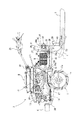
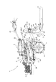
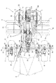
図1,2は本発明を適用した作業機の側面図及び平面図である。作業機は、施肥装置と、走行部1を有する走行機体2と、作業者が搭乗する搭乗部3と、作業機の左右バランスを向上させ且つ施肥深さを均一に保つ左右のフロート4と、作業機の前後バランスを向上させるバランスウェイト6とを備え、水田や蓮根田等の水分を多く含む足場の悪い圃場で施肥作業や代掻作業等をするためのものである。   1 and 2 are a side view and a plan view of a working machine to which the present invention is applied. The working machine includes a fertilizer application, a traveling machine body 2 having a traveling unit 1, a riding unit 3 on which an operator rides, a left and right float 4 that improves the left-right balance of the working machine and maintains a uniform fertilization depth, The balance weight 6 for improving the front-rear balance of the work machine is provided for fertilizing work, cutting work, etc. in a poorly footed field that contains a lot of water such as paddy fields and lotus fields.

施肥装置は、肥料を施肥する施肥ノズル7(施肥部)と、肥料を貯蔵する肥料タンク8と、肥料タンク8の肥料を施肥ノズル7に供給する肥料供給装置である施肥ポンプ9と、肥料タンク8から施肥ポンプ9に肥料を移送するパイプ11と、施肥ポンプ9から施肥ノズル7に肥料を移送する施肥パイプ12とにより構成され、何れも上記走行機体2上に設けられている。   The fertilizer is composed of a fertilizer nozzle 7 (fertilizer) that fertilizes fertilizer, a fertilizer tank 8 that stores fertilizer, a fertilizer pump 9 that is a fertilizer supply device that supplies fertilizer from the fertilizer tank 8 to the fertilizer nozzle 7, and a fertilizer tank 8 includes a pipe 11 that transfers fertilizer from the fertilizer pump 9 to the fertilizer pump 9, and a fertilizer pipe 12 that transfers fertilizer from the fertilizer pump 9 to the fertilizer nozzle 7, both of which are provided on the traveling machine body 2.

走行機体2は、フレーム部と、走行部である左右の車輪1,1と、エンジン13と、エンジン13の動力を上記車輪1及び施肥ポンプ9に変速伝動するミッションケース14と、上記フロート4及び施肥ノズル7を取付けるツールバー16とを備えている。   The traveling machine body 2 includes a frame part, left and right wheels 1 and 1 as a traveling part, an engine 13, a transmission case 14 that transmits power of the engine 13 to the wheel 1 and the fertilizer pump 9, and the float 4 and A tool bar 16 for attaching the fertilizer nozzle 7 is provided.

フレーム部は、前後方向の主フレーム17と、主フレーム17の後方に設けられた前後方向の縦フレーム18及び左右方向の横フレーム19とからなる。主フレーム17の後端には後方が開口した側面視略コの字形の連結部17aが、縦フレーム18の前端には前方が開口した側面視略逆コの字形状の連結部18aがそれぞれ設けられている。   The frame portion includes a main frame 17 in the front-rear direction, a vertical frame 18 in the front-rear direction, and a horizontal frame 19 in the left-right direction provided behind the main frame 17. The rear end of the main frame 17 is provided with a substantially U-shaped connecting portion 17a opened in the rear side, and the front end of the vertical frame 18 is provided with a substantially inverted U-shaped connecting portion 18a opened in the front side. It has been.

主フレーム17の連結部17aの開口部と縦フレーム18の連結部18aの開口部とが対向するようにして、主フレーム17の連結部17aの開口部に縦フレーム18の連結部18aを嵌め込む。そして、上下方向の複数のボルトを、主フレーム17の連結部17aの上方から縦フレーム18の連結部18a、主フレーム17の連結部17aの下方に挿通させることにより、縦フレーム18を主フレーム17に対して強固に固定する。縦フレーム18の連結部18aの後端面と、横フレーム19の前端面の中央部とを溶接等で連結することにより、横フレーム19を縦フレーム18及び主フレーム17に対して強固に固定する。   The connecting portion 18a of the vertical frame 18 is fitted into the opening of the connecting portion 17a of the main frame 17 so that the opening of the connecting portion 17a of the main frame 17 and the opening of the connecting portion 18a of the vertical frame 18 face each other. . Then, by inserting a plurality of bolts in the vertical direction from above the connecting portion 17a of the main frame 17 to the connecting portion 18a of the vertical frame 18 and below the connecting portion 17a of the main frame 17, the vertical frame 18 is inserted into the main frame 17. Firmly fix against. By connecting the rear end surface of the connecting portion 18 a of the vertical frame 18 and the center portion of the front end surface of the horizontal frame 19 by welding or the like, the horizontal frame 19 is firmly fixed to the vertical frame 18 and the main frame 17.

主フレーム17には上記左右の車輪1が回転自在に軸支されている。各車輪1は左右幅が広い中空状の水田車輪であり、各車輪の周面には羽根ラグ1aが複数設けられ、内部には浮き体1bが内装されている。   The left and right wheels 1 are rotatably supported on the main frame 17. Each wheel 1 is a hollow paddy wheel having a wide left and right width. A plurality of blade lugs 1a are provided on the peripheral surface of each wheel, and a floating body 1b is internally provided.

主フレーム17の上面には上記ミッションケース14が固設され、上記ミッションケース14の上部の前側にはエンジン13が、後側には後方斜め上方に向かってハンドルブラケット22延設されている。上記ハンドルブラケット22には、後方斜め上方に延びる平面視略ハの字形のハンドル23(操縦部)が設置されている。   The transmission case 14 is fixed on the upper surface of the main frame 17, the engine 13 is extended on the front side of the upper part of the transmission case 14, and the handle bracket 22 extends obliquely rearward and upward on the rear side. The handle bracket 22 is provided with a substantially C-shaped handle 23 (control part) in a plan view extending obliquely upward rearward.

横フレーム19の左右両端には、支持ステー24、保持ステー26を介して肥料タンク8が取付けられている。支持ステー24は、基端部が上方に向かって延び、中途部及び先端部が前方に向かって屈曲しており、この中途部及び先端部の上面に、側面視略U字形状の保持ステー26の中途部の下面が当接した状態で、保持ステーがボルト固定されている。この保持ステー26の前後の端部に、前後方向の肥料タンク8の前端部及び後端部をそれぞれボルト固定することにより、肥料タンク8を走行機体2の左右両側に取付ける。   Fertilizer tanks 8 are attached to the left and right ends of the horizontal frame 19 via support stays 24 and holding stays 26. The support stay 24 has a base end portion extending upward, and a midway portion and a distal end portion thereof bent forward. A holding stay 26 having a substantially U shape in side view is formed on the upper surface of the midway portion and the distal end portion. The holding stay is bolted in a state where the lower surface of the midway part is in contact. The fertilizer tank 8 is attached to the left and right sides of the traveling machine body 2 by bolting the front end portion and the rear end portion of the fertilizer tank 8 in the front-rear direction to the front and rear ends of the holding stay 26, respectively.

縦フレーム18の上方には前述の施肥ポンプ9が設置されており、後部には左右方向のツールバー16が配置されている。ツールバー16は、断面形状が略正方形状の角柱部材であり、支持フレーム27によって支持されている。支持フレーム27は、後方が開放した平面視略逆U字状の上下方向の部材であり、左右の各側板の上端前部が側面視略L字形状に切抜き形成されている。   Above the vertical frame 18, the fertilizer pump 9 is installed, and a horizontal toolbar 16 is arranged at the rear. The tool bar 16 is a prism member having a substantially square cross section, and is supported by a support frame 27. The support frame 27 is a substantially inverted U-shaped member in the vertical direction in plan view with the rear open, and the upper front ends of the left and right side plates are cut out in a substantially L shape in side view.

この左右のL字の切抜き部分によって形成される後端縁及び上端縁の長さはツールバー16の上下幅及び前後幅と略同一であり、ツールバー16の中央部の前端及び下端を上記後端縁及び上端縁に当接させて溶接等で固着することにより、支持フレーム27に左右方向のツールバー16を強固に固定する。支持フレーム27の下端部には下方に向かって延びる支持杆28が突設されている。この支持杆28の上下方向中央部分を上記縦フレーム18の後端部で固定的に支持することにより、ツールバー16が走行機体2のフレーム部に対して強固に固定される。   The lengths of the rear edge and the upper edge formed by the left and right L-shaped cutout portions are substantially the same as the vertical width and the front and rear width of the toolbar 16, and the front edge and the lower edge of the central portion of the toolbar 16 are connected to the rear edge. The tool bar 16 in the left-right direction is firmly fixed to the support frame 27 by being brought into contact with the upper edge and fixed by welding or the like. A support rod 28 is provided at the lower end of the support frame 27 so as to project downward. The tool bar 16 is firmly fixed to the frame portion of the traveling machine body 2 by fixedly supporting the vertical center portion of the support rod 28 at the rear end portion of the vertical frame 18.

上記支持構造のツールバー16には、取付部材29,31を介して上記フロート4及び施肥ノズル7が取付けられている。取付部材29,31は、側面視コの字状の部材と側面視逆コの字状の部材とに前後分割形成され、開口部を対向させた状態でツールバー16を前後で挟み込み、前後の部材同士をボルト締めすることにより、ツールバー16の側周面に締着固定される。上記構成の取付部材29,31は、ボルトを緩めることにより、ツールバー16に沿って左右方向に移動させることができるため、フロート4や施肥ノズル7の左右方向の取付位置を容易に調整できる。   The float 4 and the fertilizer nozzle 7 are attached to the toolbar 16 of the support structure via attachment members 29 and 31. The attachment members 29 and 31 are divided into front and rear U-shaped members and side-reverse U-shaped members, and sandwich the tool bar 16 in the front-rear direction with the openings facing each other. By fastening them together, they are fastened and fixed to the side peripheral surface of the toolbar 16. Since the attachment members 29 and 31 having the above-described configuration can be moved in the left-right direction along the toolbar 16 by loosening the bolts, the attachment positions in the left-right direction of the float 4 and the fertilizer nozzle 7 can be easily adjusted.

フロート4は、前後方向の板状部材で先端部が斜め上方に反り返った形状に形成され、圃場をスムーズに滑走できるように構成されており、ツールバー16の左右に、左右対称な状態でそれぞれ1個づつ設けられている。フロート4用の取付部材29の後部には上下方向の挿通孔32aを有する固定部材32が固設されている。   The float 4 is a plate-like member in the front-rear direction and is formed in a shape in which the tip portion is bent obliquely upward, and is configured to smoothly slide in the farm field. It is provided one by one. A fixing member 32 having an insertion hole 32a in the vertical direction is fixed to the rear portion of the attachment member 29 for the float 4.

この挿通穴32aに、フロート4の中央からブラケット33を介して固定的に取付けられた上下方向のステー34を挿通支持し、左右方向のボルトを固定部材32から上記ステー34に形成されたボルト孔34aに挿通させて締付固定することにより、フロート4をツールバー16に固定する。なお、ステー34の上記ボルト孔34aは上下方向に複数並べて設けられており、フロート4の取付高さが調整できるようになっている。   A vertical stay 34 that is fixedly attached from the center of the float 4 via the bracket 33 is inserted and supported in the insertion hole 32a, and a bolt in the left-right direction is formed in the stay 34 from the fixing member 32. The float 4 is fixed to the toolbar 16 by being inserted into 34 a and fastened and fixed. A plurality of the bolt holes 34a of the stay 34 are arranged in the vertical direction so that the mounting height of the float 4 can be adjusted.

施肥ノズル7は、上下方向の基端部に対して中途部が後方斜め下方に屈曲し、先端部が後方に屈曲し、基端部に施肥ポンプ9からの施肥パイプ12が接続されており、各フロート4の左右にそれぞれ1つづつ、計4つがツールバー16に取付固定されている。施肥ノズル7用の取付部材31の前部には、上下2箇所にボルト孔36aが形成された固定ブラケット36が固設されている。   The fertilizer nozzle 7 has a middle portion bent obliquely downward and rearward with respect to a base end portion in the vertical direction, a distal end portion bent backward, and a fertilizer pipe 12 from a fertilizer pump 9 is connected to the base end portion. A total of four are attached and fixed to the toolbar 16, one on each side of each float 4. A fixing bracket 36 having bolt holes 36a formed at two upper and lower portions is fixedly provided at the front portion of the attachment member 31 for the fertilizer nozzle 7.

この固定ブラケット36に、施肥ノズル7の基端部の後方に設けられた上下方向の取付座37を重ね合わせ、左右方向のボルトを、固定ブラケット36のボルト孔36aから、上記取付座37に形成されたボルト孔37aに挿通させて締付固定することにより、施肥ノズル7をツールバー16に固定する。また、施肥ノズル7の取付座37の上記ボルト孔37aは、上下方向に複数並べて設けられており、施肥ノズル7の取付高さが調整できるようになっている。なお、施肥ノズル7の取付高さは、施肥ノズル7の先端が圃場の所望の深さにまで挿入されるように、調整する。   A vertical mounting seat 37 provided behind the base end portion of the fertilizer application nozzle 7 is superimposed on the fixing bracket 36, and left and right bolts are formed on the mounting seat 37 from the bolt holes 36 a of the fixing bracket 36. The fertilizer application nozzle 7 is fixed to the tool bar 16 by being inserted into the bolt hole 37 a and tightened and fixed. A plurality of the bolt holes 37a of the mounting seat 37 of the fertilizing nozzle 7 are provided in the vertical direction so that the mounting height of the fertilizing nozzle 7 can be adjusted. The mounting height of the fertilizer nozzle 7 is adjusted so that the tip of the fertilizer nozzle 7 is inserted to a desired depth in the field.

上記構成の走行機体2の前方にバランスウェイト6が取付けられ、後方に搭乗部3が連結される。バランスウェイト6は、略直方体形状の部材であり、主フレーム17の前端に固設された取付ブラケット38によって、走行機体2の前方に固定支持されている。   The balance weight 6 is attached to the front of the traveling machine body 2 having the above configuration, and the riding section 3 is connected to the rear. The balance weight 6 is a substantially rectangular parallelepiped member, and is fixedly supported in front of the traveling machine body 2 by a mounting bracket 38 fixed to the front end of the main frame 17.

搭乗部3は、前後方向に長い平面視略長方形の板状部材であり、全体が浮き体としても機能する。搭乗部3の前部中央には上下方向の軸39の下端部が左右回動自在に支持され、この軸39の上端部は上下回動自在に前後方向のアーム41の後端部に支持されており、このアーム41の前端部が前述の支持杆28の下端部に上下回転自在に支持されている。上記回動機構により、搭乗部3は、走行機体2に対して水平バランスを保ちながら昇降させることができるとともに、走行機体2に対して左右揺動させることができる。また、搭乗部3は、平面視において4つの施肥ノズル7のうちで最内の2つの施肥ノズル7.7に挟まれ且つ側面視において施肥ノズル7と重なり合う位置に配置される。   The boarding part 3 is a plate-like member having a substantially rectangular shape in plan view that is long in the front-rear direction, and the whole functions as a floating body. A lower end portion of a vertical shaft 39 is supported at the front center of the riding portion 3 so as to be rotatable left and right, and an upper end portion of the shaft 39 is supported at a rear end portion of a front and rear arm 41 so as to be rotatable up and down. The front end of the arm 41 is supported on the lower end of the support rod 28 so as to be rotatable up and down. The riding unit 3 can be moved up and down while maintaining a horizontal balance with respect to the traveling machine body 2 and can be swung left and right with respect to the traveling machine body 2 by the rotation mechanism. Moreover, the boarding part 3 is arrange | positioned in the position which is pinched | interposed into two fertilization nozzles 7.7 of four innermost fertilization nozzles 7 in planar view, and overlaps with the fertilization nozzle 7 in side view.

上記構成の作業機によれば、水田や蓮根田等の水分を多く含んだ圃場においても、浮き体として機能する搭乗部3及び浮き体1bを内装した左右の車輪1が、浮力を受け且つ荷重を分散させるため、作業機が圃場に嵌まり込むことが防止される。そして、左右の車輪1を回転駆動させ、施肥ポンプ9の駆動により、圃場に挿入された施肥ノズル7の先端から肥料を施肥することにより、作業機は代掻作業機及び施肥作業をしながら圃場を滑走することが可能になる。   According to the working machine having the above-described configuration, the left and right wheels 1 equipped with the riding section 3 and the floating body 1b functioning as a floating body receive buoyancy and load even in a field including a lot of water such as paddy fields and lotus fields. In order to disperse, the working machine is prevented from fitting in the field. Then, the left and right wheels 1 are driven to rotate, and the fertilizer is applied from the tip of the fertilizer nozzle 7 inserted into the field by driving the fertilizer pump 9, so that the work machine performs the field work and the fertilizer work It is possible to glide.

また、左右のフロート4は走行機体2のフレーム部に固設されたツールバー16に固定されているため、作業機の左右旋回時等の左右バランスも良好に保たれる他、肥料を施肥する施肥ノズル7もツールバー16に固定されているため、施肥ノズル7の圃場に対する上下方向の位置が一定に保たれ、施肥深さを均一できる。   In addition, since the left and right floats 4 are fixed to a tool bar 16 fixed to the frame portion of the traveling machine body 2, the left and right balance when the working machine is turned left and right is maintained well and fertilizer is applied. Since the nozzle 7 is also fixed to the tool bar 16, the vertical position of the fertilizer nozzle 7 with respect to the field is kept constant, and the fertilization depth can be made uniform.

また、搭乗部3を走行機体2に対して昇降可能に連結しているため、作業者の自重により搭乗部3が圃場に沈み込んだ場合でも、施肥ノズル7の圃場に対する上下位置を略一定に保つことができる他、搭乗部3を走行機体2に対して左右回動可能に構成することにより、作業機の旋回性能が向上する。   Moreover, since the boarding part 3 is connected to the traveling machine body 2 so as to be movable up and down, even when the boarding part 3 sinks into the field due to the weight of the operator, the vertical position of the fertilizer nozzle 7 with respect to the field is made substantially constant. In addition to being able to maintain, by configuring the riding section 3 so as to be turnable to the left and right with respect to the traveling machine body 2, the turning performance of the work implement is improved.

さらに、肥料タンク8を走行機体2の左右に各1個づつ設けるため、作業機の左右バランスが悪化することが防止される他、左右の肥料タンク8内の肥料を同時に消費させていくことにより、作業機の左右バランスを常に良好に保つことができる。そして、肥料タンク8から施肥ポンプ9までの距離及び施肥ポンプ9から施肥ノズル7までの距離が短いため、前述のパイプ11及び施肥パイプ12の配管が容易になる。   Furthermore, since one fertilizer tank 8 is provided on each of the left and right sides of the traveling machine body 2, the left and right balance of the work equipment is prevented from being deteriorated, and the fertilizer in the left and right fertilizer tanks 8 is consumed simultaneously. , The left and right balance of the work machine can always be kept good. And since the distance from the fertilizer tank 8 to the fertilizer pump 9 and the distance from the fertilizer pump 9 to the fertilizer nozzle 7 are short, piping of the above-mentioned pipe 11 and the fertilizer pipe 12 becomes easy.

なお、ハンドル23、肥料タンク8、施肥ポンプ12及び施肥ノズル7を走行機体1に設置し、搭乗部3を側面視において施肥ノズル7と重なり合う位置に配置することにより、作業機の前後長が短くなり、作業機全体をコンパクトにすることができるとともに、作業機の旋回性能も向上する。   In addition, by installing the handle 23, the fertilizer tank 8, the fertilizer pump 12 and the fertilizer nozzle 7 in the traveling machine body 1 and arranging the riding section 3 at a position overlapping the fertilizer nozzle 7 in a side view, the front and rear length of the working machine is short. Thus, the entire work machine can be made compact, and the turning performance of the work machine can be improved.

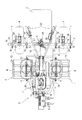
以上、走行機体1の後部に施肥ポンプ9を設けた例につき説明したが、図3,4は施肥ポンプ9を走行機体1の前方に設けた例につき示している。以下、図1,2に示す実施例と異なる構成について説明すると、主フレーム17の前端に設けられた取付ブラケット38に、施肥ポンプ9を取付けて、この施肥ポンプ9によりバランスウェイト6を構成する。また、ツールバー16を支持する支持フレーム27の前端部に、縦フレーム18の後端部を溶接等で一体的に取付けることにより、ツールバー16が走行機体2のフレーム部に対して強固に固定され、搭乗部3が走行機体2の後方に連結される。   The example in which the fertilizer pump 9 is provided at the rear part of the traveling machine body 1 has been described above, but FIGS. 3 and 4 show an example in which the fertilizer pump 9 is provided in front of the traveling machine body 1. 1 and 2, the fertilizer pump 9 is attached to a mounting bracket 38 provided at the front end of the main frame 17, and the balance weight 6 is configured by the fertilizer pump 9. Further, the tool bar 16 is firmly fixed to the frame part of the traveling machine body 2 by integrally attaching the rear end part of the vertical frame 18 to the front end part of the support frame 27 that supports the tool bar 16 by welding or the like. The riding section 3 is connected to the rear of the traveling machine body 2.

上記構成の作業機によれば、施肥ポンプ9がバランスウェイト6の役割も果たし、別途バランスウェイトを設ける必要がないため、作業機全体の部品点が減少し、構造がシンプルになり、製造コストを低く抑えることが可能になる。   According to the working machine configured as described above, the fertilizer pump 9 also serves as the balance weight 6 and there is no need to provide a separate balance weight. Therefore, the number of parts of the entire work machine is reduced, the structure is simplified, and the manufacturing cost is reduced. It becomes possible to keep it low.

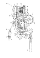
図5,6は、他の実施例を示した作業機の側面図及び平面図である。図1,2に示す実施例の走行機体2の前部が本作業機の走行機体2の後部を、後部が本作業機2の走行機体の前部を構成している。ミッションケース14からは、後方(図5における左方向)斜め上方に向かってハンドル23及びハンドル23を支持するハンドルブラケット22が固設されている。主フレーム17の後端(図1,2における前端)の取付ブラケット38に、ツールバー16を支持する支持フレーム27の前端部を強固に固定することにより、ツールバー16が走行機体2のフレーム部に対して強固に固定されるとともに、搭乗部3が走行機体2の後方に連結される。   5 and 6 are a side view and a plan view of a working machine showing another embodiment. The front part of the traveling machine body 2 of the embodiment shown in FIGS. 1 and 2 constitutes the rear part of the traveling machine body 2 of the working machine, and the rear part constitutes the front part of the traveling machine body of the working machine 2. From the mission case 14, a handle 23 and a handle bracket 22 that supports the handle 23 are fixedly provided rearward (leftward in FIG. 5) obliquely upward. By firmly fixing the front end portion of the support frame 27 that supports the tool bar 16 to the mounting bracket 38 at the rear end (the front end in FIGS. 1 and 2) of the main frame 17, the tool bar 16 is attached to the frame portion of the traveling machine body 2. And the riding section 3 is connected to the rear of the traveling machine body 2.

施肥ポンプ9は図1,2に示す実施例と略同一の構成により、縦フレーム18上に支持されている。肥料タンク8を支持する左右の支持ステー24は、横フレーム19の左右端からそれぞれ上方に向かって突設されており、各支持ステー24の上端に側面視略U字形状の保持ステー26の中央部分が固定されている。肥料タンク8のその他の支持構造は、図1,2に示す実施例の肥料タンク8の支持構造と略同一であり、本作業機は図1,2に示す実施例の作業機と比較してより前方に肥料タンク8が配置されている。そして、走行機体2を前進操作(図1,2に示す実施例においては後進操作)することにより、本作業機の走行機体2は前進駆動し、作業機も前進する。   The fertilizer pump 9 is supported on the vertical frame 18 by substantially the same configuration as the embodiment shown in FIGS. The left and right support stays 24 that support the fertilizer tank 8 protrude upward from the left and right ends of the horizontal frame 19, respectively, and the upper ends of the support stays 24 are arranged at the center of a substantially U-shaped holding stay 26 in a side view. The part is fixed. The other support structure of the fertilizer tank 8 is substantially the same as the support structure of the fertilizer tank 8 of the embodiment shown in FIGS. 1 and 2, and this working machine is compared with the working machine of the embodiment shown in FIGS. A fertilizer tank 8 is arranged further forward. Then, by operating the traveling machine body 2 forward (reverse operation in the embodiment shown in FIGS. 1 and 2), the traveling machine body 2 of the present working machine is driven forward, and the working machine is also advanced.

上記構成の作業機によれば、前方に施肥ポンプ9を設け、該施肥ポンプ9によりバランスウェイト6を構成した場合においても、施肥ポンプ9と肥料タンク8とを近接させて設けることができるため、肥料タンク8から施肥ポンプ9に肥料を移送するパイプ11の配管が容易にできる。   According to the working machine having the above configuration, the fertilizer pump 9 is provided in the front, and even when the balance weight 6 is configured by the fertilizer pump 9, the fertilizer pump 9 and the fertilizer tank 8 can be provided close to each other. The pipe 11 for transferring the fertilizer from the fertilizer tank 8 to the fertilizer pump 9 can be easily provided.

本発明を適用した作業機の側面図である。It is a side view of the working machine to which the present invention is applied. 本発明を適用した作業機の平面図である。It is a top view of the working machine to which this invention is applied. 他の実施例を示す作業機の側面図である。It is a side view of the working machine which shows another Example. 他の実施例を示す作業機の平面図である。It is a top view of the working machine which shows another Example. 他の実施例を示す作業機の側面図である。It is a side view of the working machine which shows another Example. 他の実施例を示す作業機の平面図である。It is a top view of the working machine which shows another Example.

符号の説明Explanation of symbols

1 車輪(走行部)
2 走行機体
3 搭乗部
7 施肥ノズル(施肥部)
9 施肥ポンプ(肥料供給装置)
23 ハンドル(操縦部)
1 wheel (traveling part)
2 traveling machine body 3 boarding part 7 fertilizer nozzle (fertilizer part)
9 Fertilizer pump (fertilizer supply device)
23 Handle (control section)

Claims (3)

走行部(1)を有する走行機体(2)と、走行機体(2)に連結され作業者が搭乗する搭乗部(3)と、肥料を施肥する施肥部(7)と、施肥部(7)に肥料を供給する肥料供給装置(9)とを備え、圃場を滑走して肥料を施肥する施肥作業機において、走行機体(2)の後方に施肥部(7)と搭乗部(3)及び操縦部(23)とを備え、該搭乗部(3)の前方に肥料供給装置(9)を設けた施肥作業機。   A traveling machine body (2) having a traveling part (1), a boarding part (3) connected to the traveling machine body (2) and on which an operator rides, a fertilizer application part (7) for fertilizing fertilizer, and a fertilizer application part (7) And a fertilizer supply device (9) for supplying fertilizer to a fertilizer application machine for applying fertilizer by sliding on a farm field, a fertilizer section (7), a riding section (3) and a maneuvering unit behind a traveling machine body (2) And a fertilizer application machine provided with a fertilizer supply device (9) in front of the riding section (3). 走行機体(2)の後部に肥料供給装置(9)を設けた請求項1の施肥作業機。   The fertilizer application machine according to claim 1, wherein a fertilizer supply device (9) is provided at a rear portion of the traveling machine body (2). 走行機体(2)の前部に肥料供給装置(9)を設けた請求項1の施肥作業機。   The fertilizer application machine according to claim 1, wherein a fertilizer supply device (9) is provided at a front portion of the traveling machine body (2).
JP2007013143A 2007-01-23 2007-01-23 Fertilizing working machine Pending JP2008178317A (en)

Priority Applications (1)

Application Number Priority Date Filing Date Title
JP2007013143A JP2008178317A (en) 2007-01-23 2007-01-23 Fertilizing working machine

Applications Claiming Priority (1)

Application Number Priority Date Filing Date Title
JP2007013143A JP2008178317A (en) 2007-01-23 2007-01-23 Fertilizing working machine

Publications (1)

Publication Number Publication Date
JP2008178317A true JP2008178317A (en) 2008-08-07

Family

ID=39722718

Family Applications (1)

Application Number Title Priority Date Filing Date
JP2007013143A Pending JP2008178317A (en) 2007-01-23 2007-01-23 Fertilizing working machine

Country Status (1)

Country Link
JP (1) JP2008178317A (en)

Cited By (1)

* Cited by examiner, † Cited by third party
Publication number Priority date Publication date Assignee Title
JP2009118795A (en) * 2007-11-15 2009-06-04 Mitsubishi Agricult Mach Co Ltd Fertilizing implement

Citations (7)

* Cited by examiner, † Cited by third party
Publication number Priority date Publication date Assignee Title
JPS5335827A (en) * 1976-09-14 1978-04-03 Nippon Denso Co Ltd Ignition timing control system for internal combustion engine
JPS6189218A (en) * 1984-10-08 1986-05-07 Asahi Chem Ind Co Ltd Granular polymer and its production
JPS61186323A (en) * 1985-02-14 1986-08-20 Tsumura Juntendo Inc Carcinostatic agent
JPS6245905A (en) * 1985-08-21 1987-02-27 Nippon Kokan Kk <Nkk> Extractor for gland leak steam in turbine
JPS62164725A (en) * 1986-01-14 1987-07-21 Nippon Ester Co Ltd Polyester sealant
JPH02106480A (en) * 1988-10-13 1990-04-18 Hino Motors Ltd Simple car
JP2004057082A (en) * 2002-07-29 2004-02-26 Iseki & Co Ltd Fertilizer spray apparatus for paddy field of lotus root

Patent Citations (7)

* Cited by examiner, † Cited by third party
Publication number Priority date Publication date Assignee Title
JPS5335827A (en) * 1976-09-14 1978-04-03 Nippon Denso Co Ltd Ignition timing control system for internal combustion engine
JPS6189218A (en) * 1984-10-08 1986-05-07 Asahi Chem Ind Co Ltd Granular polymer and its production
JPS61186323A (en) * 1985-02-14 1986-08-20 Tsumura Juntendo Inc Carcinostatic agent
JPS6245905A (en) * 1985-08-21 1987-02-27 Nippon Kokan Kk <Nkk> Extractor for gland leak steam in turbine
JPS62164725A (en) * 1986-01-14 1987-07-21 Nippon Ester Co Ltd Polyester sealant
JPH02106480A (en) * 1988-10-13 1990-04-18 Hino Motors Ltd Simple car
JP2004057082A (en) * 2002-07-29 2004-02-26 Iseki & Co Ltd Fertilizer spray apparatus for paddy field of lotus root

Cited By (1)

* Cited by examiner, † Cited by third party
Publication number Priority date Publication date Assignee Title
JP2009118795A (en) * 2007-11-15 2009-06-04 Mitsubishi Agricult Mach Co Ltd Fertilizing implement

Similar Documents

Publication Publication Date Title
JP2019000070A (en) Work vehicle
JP2009179960A (en) Construction equipment
US9382692B2 (en) Seat stand and working machine including same
JP2008178317A (en) Fertilizing working machine
KR101551478B1 (en) Front loader and front loader with a Agricultural
JP2008178318A (en) Fertilizing working machine
JP4901699B2 (en) Fertilizer application machine
JP5722741B2 (en) Preliminary seedling placement structure for riding rice transplanter
JP2010059734A5 (en)
JP4814709B2 (en) Construction machinery
JP5727275B2 (en) Paddy field machine
JP2004357651A (en) Seeding machine with fertilizer applicator
JP2006211916A (en) Fertilizing machine
JP6669057B2 (en) Transplant machine
JP2009136264A (en) Fertilizing implement
JP2002045013A (en) Body structure for implement for paddy field
JP2013112978A (en) Work vehicle
JP2009005663A (en) Ridge formation-tending machine
JP5250004B2 (en) Rotary tillage device
JP2006101839A (en) Riding-type tea garden-tending machine
JP2007267615A (en) Agricultural feeding device
JP2007259743A (en) Float of seedling transplanter
JP2008082128A (en) Loader working machine
JP2008254520A (en) Supporting frame structure of construction machine
JP3930173B2 (en) Support structure for transmission case in traveling vehicle

Legal Events

Date Code Title Description
A621 Written request for application examination

Effective date: 20090731

Free format text: JAPANESE INTERMEDIATE CODE: A621

A977 Report on retrieval

Effective date: 20110707

Free format text: JAPANESE INTERMEDIATE CODE: A971007

A131 Notification of reasons for refusal

Effective date: 20110719

Free format text: JAPANESE INTERMEDIATE CODE: A131

A521 Written amendment

Effective date: 20110916

Free format text: JAPANESE INTERMEDIATE CODE: A523

A02 Decision of refusal

Free format text: JAPANESE INTERMEDIATE CODE: A02

Effective date: 20111122