JP2008153645A - Method and unit for stabilizing output average of radiation emitted from pulsed radioactive source - Google Patents
Method and unit for stabilizing output average of radiation emitted from pulsed radioactive source Download PDFInfo
- Publication number
- JP2008153645A JP2008153645A JP2007305689A JP2007305689A JP2008153645A JP 2008153645 A JP2008153645 A JP 2008153645A JP 2007305689 A JP2007305689 A JP 2007305689A JP 2007305689 A JP2007305689 A JP 2007305689A JP 2008153645 A JP2008153645 A JP 2008153645A
- Authority
- JP
- Japan
- Prior art keywords
- pulse
- radiation
- pulse energy
- energy
- current
- Prior art date
- Legal status (The legal status is an assumption and is not a legal conclusion. Google has not performed a legal analysis and makes no representation as to the accuracy of the status listed.)
- Pending
Links
- 230000005855 radiation Effects 0.000 title claims abstract description 147
- 238000000034 method Methods 0.000 title claims abstract description 50
- 230000000087 stabilizing effect Effects 0.000 title claims abstract description 9
- 230000002285 radioactive effect Effects 0.000 title abstract 2
- 238000005259 measurement Methods 0.000 claims description 25
- 230000003287 optical effect Effects 0.000 claims description 13
- 238000001459 lithography Methods 0.000 claims description 9
- 239000004065 semiconductor Substances 0.000 claims description 9
- 238000009826 distribution Methods 0.000 claims description 6
- 230000005540 biological transmission Effects 0.000 claims description 5
- 238000004519 manufacturing process Methods 0.000 claims description 5
- 238000004364 calculation method Methods 0.000 claims description 4
- 230000006698 induction Effects 0.000 claims description 4
- 230000001960 triggered effect Effects 0.000 claims description 4
- 230000009471 action Effects 0.000 claims description 3
- 238000001514 detection method Methods 0.000 claims 2
- 230000007423 decrease Effects 0.000 claims 1
- 238000004422 calculation algorithm Methods 0.000 description 9
- 238000010586 diagram Methods 0.000 description 5
- 230000008859 change Effects 0.000 description 4
- 230000008569 process Effects 0.000 description 4
- 238000004088 simulation Methods 0.000 description 4
- 230000002123 temporal effect Effects 0.000 description 4
- 238000013139 quantization Methods 0.000 description 3
- 230000009467 reduction Effects 0.000 description 3
- 230000008901 benefit Effects 0.000 description 2
- 230000003247 decreasing effect Effects 0.000 description 2
- 230000005284 excitation Effects 0.000 description 2
- 238000003384 imaging method Methods 0.000 description 2
- 238000000206 photolithography Methods 0.000 description 2
- 238000012546 transfer Methods 0.000 description 2
- 238000012935 Averaging Methods 0.000 description 1
- 230000008033 biological extinction Effects 0.000 description 1
- 238000011161 development Methods 0.000 description 1
- 238000006073 displacement reaction Methods 0.000 description 1
- 230000000694 effects Effects 0.000 description 1
- 238000001900 extreme ultraviolet lithography Methods 0.000 description 1
- 238000001914 filtration Methods 0.000 description 1
- 230000006872 improvement Effects 0.000 description 1
- 230000007774 longterm Effects 0.000 description 1
- 230000004048 modification Effects 0.000 description 1
- 238000012986 modification Methods 0.000 description 1
- 238000001208 nuclear magnetic resonance pulse sequence Methods 0.000 description 1
- 238000012545 processing Methods 0.000 description 1
- 238000010791 quenching Methods 0.000 description 1
- 230000000171 quenching effect Effects 0.000 description 1
- 230000035945 sensitivity Effects 0.000 description 1
- 239000007787 solid Substances 0.000 description 1
- 230000006641 stabilisation Effects 0.000 description 1
- 238000011105 stabilization Methods 0.000 description 1
- 239000000758 substrate Substances 0.000 description 1
- 230000001360 synchronised effect Effects 0.000 description 1
- 230000001052 transient effect Effects 0.000 description 1
Images


Classifications
-
- G—PHYSICS
- G03—PHOTOGRAPHY; CINEMATOGRAPHY; ANALOGOUS TECHNIQUES USING WAVES OTHER THAN OPTICAL WAVES; ELECTROGRAPHY; HOLOGRAPHY
- G03B—APPARATUS OR ARRANGEMENTS FOR TAKING PHOTOGRAPHS OR FOR PROJECTING OR VIEWING THEM; APPARATUS OR ARRANGEMENTS EMPLOYING ANALOGOUS TECHNIQUES USING WAVES OTHER THAN OPTICAL WAVES; ACCESSORIES THEREFOR
- G03B27/00—Photographic printing apparatus
- G03B27/72—Controlling or varying light intensity, spectral composition, or exposure time in photographic printing apparatus
-
- G—PHYSICS
- G01—MEASURING; TESTING
- G01J—MEASUREMENT OF INTENSITY, VELOCITY, SPECTRAL CONTENT, POLARISATION, PHASE OR PULSE CHARACTERISTICS OF INFRARED, VISIBLE OR ULTRAVIOLET LIGHT; COLORIMETRY; RADIATION PYROMETRY
- G01J1/00—Photometry, e.g. photographic exposure meter
- G01J1/10—Photometry, e.g. photographic exposure meter by comparison with reference light or electric value provisionally void
- G01J1/16—Photometry, e.g. photographic exposure meter by comparison with reference light or electric value provisionally void using electric radiation detectors
- G01J1/18—Photometry, e.g. photographic exposure meter by comparison with reference light or electric value provisionally void using electric radiation detectors using comparison with a reference electric value
-
- G—PHYSICS
- G01—MEASURING; TESTING
- G01J—MEASUREMENT OF INTENSITY, VELOCITY, SPECTRAL CONTENT, POLARISATION, PHASE OR PULSE CHARACTERISTICS OF INFRARED, VISIBLE OR ULTRAVIOLET LIGHT; COLORIMETRY; RADIATION PYROMETRY
- G01J1/00—Photometry, e.g. photographic exposure meter
- G01J1/42—Photometry, e.g. photographic exposure meter using electric radiation detectors
- G01J1/4257—Photometry, e.g. photographic exposure meter using electric radiation detectors applied to monitoring the characteristics of a beam, e.g. laser beam, headlamp beam
-
- G—PHYSICS
- G01—MEASURING; TESTING
- G01J—MEASUREMENT OF INTENSITY, VELOCITY, SPECTRAL CONTENT, POLARISATION, PHASE OR PULSE CHARACTERISTICS OF INFRARED, VISIBLE OR ULTRAVIOLET LIGHT; COLORIMETRY; RADIATION PYROMETRY
- G01J11/00—Measuring the characteristics of individual optical pulses or of optical pulse trains
-
- G—PHYSICS
- G03—PHOTOGRAPHY; CINEMATOGRAPHY; ANALOGOUS TECHNIQUES USING WAVES OTHER THAN OPTICAL WAVES; ELECTROGRAPHY; HOLOGRAPHY
- G03F—PHOTOMECHANICAL PRODUCTION OF TEXTURED OR PATTERNED SURFACES, e.g. FOR PRINTING, FOR PROCESSING OF SEMICONDUCTOR DEVICES; MATERIALS THEREFOR; ORIGINALS THEREFOR; APPARATUS SPECIALLY ADAPTED THEREFOR
- G03F7/00—Photomechanical, e.g. photolithographic, production of textured or patterned surfaces, e.g. printing surfaces; Materials therefor, e.g. comprising photoresists; Apparatus specially adapted therefor
- G03F7/70—Microphotolithographic exposure; Apparatus therefor
- G03F7/70008—Production of exposure light, i.e. light sources
- G03F7/70041—Production of exposure light, i.e. light sources by pulsed sources, e.g. multiplexing, pulse duration, interval control or intensity control
-
- G—PHYSICS
- G03—PHOTOGRAPHY; CINEMATOGRAPHY; ANALOGOUS TECHNIQUES USING WAVES OTHER THAN OPTICAL WAVES; ELECTROGRAPHY; HOLOGRAPHY
- G03F—PHOTOMECHANICAL PRODUCTION OF TEXTURED OR PATTERNED SURFACES, e.g. FOR PRINTING, FOR PROCESSING OF SEMICONDUCTOR DEVICES; MATERIALS THEREFOR; ORIGINALS THEREFOR; APPARATUS SPECIALLY ADAPTED THEREFOR
- G03F7/00—Photomechanical, e.g. photolithographic, production of textured or patterned surfaces, e.g. printing surfaces; Materials therefor, e.g. comprising photoresists; Apparatus specially adapted therefor
- G03F7/70—Microphotolithographic exposure; Apparatus therefor
- G03F7/70483—Information management; Active and passive control; Testing; Wafer monitoring, e.g. pattern monitoring
- G03F7/7055—Exposure light control in all parts of the microlithographic apparatus, e.g. pulse length control or light interruption
- G03F7/70558—Dose control, i.e. achievement of a desired dose
Abstract
Description
本発明は、特にガス放電プラズマ(GDP:gas-discharge plasma)又はレーザー生成プラズマ(LPP:laser produced plasma)に基づくEUV源、エキシマレーザ、F2レーザ又はその他のパルス駆動される放射線源による、放射線源の放出される放射線の平均出力を安定化するための方法及び装置に関している。その様な線源の好ましい応用範囲は電気回路を製造する為の半導体リソグラフィである。 The present invention is particularly gas discharge plasma (GDP: gas-discharge plasma) or a laser produced plasma (LPP: laser produced plasma) EUV sources based on, by Excimer laser, F 2 laser or other pulsed driven radiation source, the radiation The present invention relates to a method and apparatus for stabilizing the average power of emitted radiation of a source. A preferred application range of such a source is semiconductor lithography for producing electrical circuits.
半導体産業の光リソグラフィ法では、所謂スキャナで(転写される構造を有する)マスクが縮小されて半導体基板(ウエハ)上へ転写される。 In the optical lithography method of the semiconductor industry, a mask (having a transfer structure) is reduced by a so-called scanner and transferred onto a semiconductor substrate (wafer).
光リソグラフィ法の質は、光学システムの特性(開口数、焦点深度、レンズ又は鏡の転写エラー)のほか、本質的に、入射される放射線量をどれだけ厳密に維持できるかによって決定される。この線量精度(Dosisstabilitaet(英語:dose accuracy))は、非特許文献1によれば
a)パルスの量子化(Impuls-Quantisierung)
b)パルス‐パルス安定性(Puls-zu-Plus-Stabilitaet)及び
c)放出体積の空間的安定性
によって決定される。
The quality of the optical lithography method is determined by the characteristics of the optical system (numerical aperture, depth of focus, lens or mirror transfer error) and, in essence, how closely the incident radiation dose can be maintained. According to
b) determined by the pulse-pulse stability (Puls-zu-Plus-Stabilitaet) and c) the spatial stability of the emission volume.
その際、パルスの量子化a)はスキャナ固有である。走査(英語:scan)の間に可動スリット(英語:moving slit)へ入る光パルスの数は可変である。パルスの量子化を最適化するための方法は例えば特許文献1に開示される。 The pulse quantization a) is then unique to the scanner. The number of light pulses that enter the moving slit during scanning is variable. A method for optimizing pulse quantization is disclosed, for example, in US Pat.
b)及びc)の量は放射線源そのものに対し固有であり、その際c)の量は放射線を発生するプラズマの検出可能な変動(Fluktuation)に基づくEUV源の為にのみ重要である。 The quantities b) and c) are specific to the radiation source itself, in which case the quantity c) is only important for EUV sources based on detectable fluctuations in the plasma generating the radiation.
今日一般的な露光プロセスでは、特別な光源により照射されるマスクは、縮小されてウエハ上へ写し取られる。露光の為、放射線源として現在のところ248nm及び193nmの波長での狭帯域のエキシマレーザが使用される。更に、157nmのF2レーザに基づくシステムが開発中であり、又、より短い波長への動向は目下のところ13nm周辺の波長を有するプラズマに基づくEUV放射線源によって続けられる。 In a common exposure process today, a mask irradiated by a special light source is reduced and copied onto a wafer. For exposure, currently narrow band excimer lasers at wavelengths of 248 nm and 193 nm are used as radiation sources. In addition, systems based on 157 nm F 2 lasers are under development, and the trend towards shorter wavelengths is currently continued by plasma-based EUV radiation sources with wavelengths around 13 nm.
その際、ウエハ表面上でそれぞれの放射線パルスが放射スポットを生じ、上記放射スポットはマスク及びウエハの同期運動により、ウエハ表面上でパルスからパルスへ僅かに変位して生じる。 In this case, each radiation pulse generates a radiation spot on the wafer surface, and the radiation spot is generated by a slight displacement from pulse to pulse on the wafer surface by the synchronous movement of the mask and the wafer.
通常は回路に対応する、ウエハ上で実行される露光エリア(英語:die)の各露光の為に、放射線源は既定の放射パルス(バースト)のパルスシーケンスを放射し、それらパルスの一部は、移動速度、イメージング光学素子の縮小、及び露光フィールドサイズに対応して、光感受性の層をウエハ表面上の特定の位置で全露光する為に貢献する。 For each exposure area (English: die) performed on a wafer, usually corresponding to a circuit, the radiation source emits a predetermined pulse sequence of radiation pulses (bursts), some of which are Corresponding to speed of movement, reduction of imaging optics, and exposure field size, the light sensitive layer contributes to full exposure at a specific location on the wafer surface.
半導体メーカーは、(ウエハ表面の特定の位置での)線量の安定性に関する、パルス‐パルス安定性について極めて高い要求をする。これは現在のパルスエネルギの平均値又はパルスエネルギーの目標値(指定エネルギ)からの、現在のパルスエネルギの標準偏差σによって表される。DUVリソグラフィ及びVUVリソグラフィの場合、狭帯域のエキシマレーザの為にはσD<1.5%の線量安定性が要求され、一方EUVリソグラフィの為にはσD<0.3%の線量安定性が必要となる。 Semiconductor manufacturers make very high demands on pulse-to-pulse stability with respect to dose stability (at a specific location on the wafer surface). This is represented by the standard value σ of the current pulse energy from the average value of the current pulse energy or the target value (designated energy) of the pulse energy. For DUV and VUV lithography, a dose stability of σ D <1.5% is required for narrowband excimer lasers, whereas a dose stability of σ D <0.3% is required for EUV lithography. Is required.
これらの要求は、パルス‐パルス基準(Basis)での放射線出力の能動的な調整よってのみ満たすことが出来る。この目的の為に既知の方法は全て、次のパルスの単独パルスエネルギの基準値ES,i+1:

その様な方法は例えば特許文献1で紹介される。そこにはパルス‐パルスエネルギ制御が記載され、それは発光、光パルスエネルギの測定、駆動レーザの充電電圧及び更新された発光からなる閉じた制御ループに基づいている。それにより、上記制御は数1に従う調整原理に対応する。
Such a method is introduced in
その際、適した方法で次のパルスのエネルギの基準値ES,i+1と、1つ又は複数の適当な操作変数Sn,i+1(例えば、ガス放電駆動の放射線源での充電電圧)の間の関係式gn(…)を作成することは、各技術者の経験に委ねられたままである。
特許文献2はパルス付けられる放射線源の為の調整方法を開示する。上記方法は、先の測定値から比例制御の比例定数をパルスエネルギ及び操作変数の為に常に新しく決定し、またそれによって調整をより正確に行う為に有効である。 U.S. Pat. No. 6,057,051 discloses an adjustment method for a pulsed radiation source. The above method is effective for constantly determining the proportionality constant of the proportional control from the previous measurement values for the pulse energy and the manipulated variable, and thereby making the adjustment more accurate.
特許文献3はエキシマレーザ系の為の具体的実施を記載する。ここで、充電電圧とレーザのパルスエネルギへの作用の間の関係の優れた知識によって調整は最適化される。そしてそれにより、この調整は一般的な関係gn(…)に該当する。 U.S. Patent No. 6,057,031 describes a specific implementation for an excimer laser system. Here, the adjustment is optimized by a good knowledge of the relationship between the charging voltage and the effect on the pulse energy of the laser. Thereby, this adjustment corresponds to the general relationship g n (...).
更に、特許文献4は複数の操作変数Sn,i+1(ここでは充電電圧及びガス圧)に関して調整出来ることを記載する。 Furthermore, Patent Document 4 describes that adjustment is possible with respect to a plurality of manipulated variables Sn, i + 1 (here, charging voltage and gas pressure).
特許文献5に記載されるようなその他の方法は、過渡効果を初期段階で補償可能にする為、バーストの第1パルスの間に、調整アルゴリズムの最適化に取り組む。 Other methods, such as those described in US Pat. No. 5,637,028, work on optimizing the adjustment algorithm during the first pulse of the burst in order to be able to compensate for transient effects at an early stage.
これら上述の方法の全ては、それらが次の放射線パルスの為に基準値を意図的に変更することに基づいている点で共通している。個々の文献は、次の光パルスを可能な限り正確にパルスエネルギの目的値に適合させる為に、次のエネルギ値がどのように決定されるか、又は、放射線源がどのように制御されるか、という方法においてのみ異なっている。 All of these above-mentioned methods are common in that they are based on deliberately changing the reference value for the next radiation pulse. Individual documents show how the next energy value is determined or how the radiation source is controlled in order to adapt the next light pulse to the target value of the pulse energy as accurately as possible. It differs only in the way.
特許文献6では、光量が可変である光パルスを放射する為のパルス光源を含む装置が開示される。その際、光パルスの強度が測定される、また、ターゲット(マスク)上に透過される強度は可変の光低減ユニットによって制御される。 Patent Document 6 discloses an apparatus including a pulse light source for emitting an optical pulse having a variable amount of light. In that case, the intensity of the light pulse is measured and the intensity transmitted onto the target (mask) is controlled by a variable light reduction unit.
その為、特許文献7には改良された装置が記載される。その際ここで、先ずパルスエネルギの測定が行われることで、追加的に光パルスの間隔について考慮される、その後露光面上での必要な線量の為にパルスがどれだけ必要とされるかが算出され、そしてパルスの時間経過からマスク及びウエハ上でのスキャン速度が確定される。スキャン速度が確定されると、有利には光強度は、精確なフィルタリングを介してパルスの数の変更が行われる必要がないように、調節される。しかしながら一方で平均光量がより少なくなる場合、必要な線量に達する為、パルスの数が1つずつ上げられる。 Therefore, Patent Document 7 describes an improved apparatus. In this case, the pulse energy is first measured, so that the interval between the light pulses is additionally taken into account, and then how many pulses are needed for the required dose on the exposure surface. And the scan speed on the mask and wafer is determined from the time lapse of the pulse. Once the scan speed is determined, the light intensity is advantageously adjusted so that no change in the number of pulses needs to be made through precise filtering. However, on the other hand, if the average light quantity is lower, the number of pulses is increased by one to reach the required dose.
類似の手段は特許文献8にも記載される。その場合、入射されたパルスエネルギの測定及び前記パルスのパルス周波数の特定後、パルスエネルギは次のパルスの為に適合され、それによりスキャン速度を等しく保つことが可能である。 Similar means are also described in US Pat. In that case, after measuring the incident pulse energy and determining the pulse frequency of said pulse, the pulse energy can be adapted for the next pulse, thereby keeping the scanning speed equal.
上述の3つの文献には欠点がある。それは、必要な線量を調節する為、及び、要求される線量精度を達成する為に、予め与えられたスキャン速度及び露光される領域の窓関数での所定のパルス数の場合、放出されるパルスの平均エネルギからのみ、ウエハ平面で、パルスエネルギを明確に適合することが出来るということである。放射線パルスの周波数は、利用可能なパルスエネルギに依存して必要な線量を確実に獲得する為に確かに考慮されるが、しかし、線量精度を調節する為に微調整された可変性の消光フィルタ(extinction filter)を用いて排他的にパルスエネルギを調整する為に、露光プロセスの為に一定に選ばれる。 The above three documents have drawbacks. In order to adjust the required dose and to achieve the required dose accuracy, the pulses emitted for a given number of pulses at a given scan speed and window function of the exposed area This means that the pulse energy can be clearly matched at the wafer plane only from the average energy. The frequency of the radiation pulse is certainly taken into account to ensure that the required dose is obtained depending on the available pulse energy, but a variable quenching filter that is fine-tuned to adjust the dose accuracy. In order to adjust the pulse energy exclusively using (extinction filter), it is chosen constant for the exposure process.
しかしながら多くの場合で、パルスエネルギの素早いパルス‐パルス調整を可能にする適切で信頼できる関係gn(…)は見つけられていない。特に、例えば光学システムのイメージング特性がウエハ平面で測定される放射線強度に影響を与える場合、上述の全ての調整方法で用いられるガス放電用の充電電圧の制御は機能不能となり得る。 In many cases, however, no suitable and reliable relationship g n (...) has been found that allows for rapid pulse-to-pulse adjustment of the pulse energy. In particular, if the imaging characteristics of the optical system affect the radiation intensity measured at the wafer plane, the control of the charging voltage for gas discharge used in all the adjustment methods described above may be disabled.
従って、特にエネルギの時間変動に加えて空間的なプラズマの変動を有するプラズマに基づく放射線源の場合、そうでなければ通常良好な充電電圧とパルスエネルギの間の相関関係は、敏感に妨げられる。その為、空間的なプラズマの変化により(例えば光学システムのエタンデュ‐リミッティング(Etendue-Limitierung)により)プラズマで発生するエネルギの上昇はウエハへの経路上で失われる。このような場合、充電電圧を制御することによるパルスエネルギの調整は成功しない。 Thus, especially in the case of plasma-based radiation sources with spatial plasma fluctuations in addition to time fluctuations of energy, the correlation between otherwise normally good charging voltage and pulse energy is sensitively disturbed. Thus, due to spatial plasma changes (eg, due to Etendue-Limitierung of the optical system), the increase in energy generated in the plasma is lost on the path to the wafer. In such a case, the adjustment of the pulse energy by controlling the charging voltage is not successful.
更に、効果的な調整の為に必要な関係gn(…)は、調整アルゴリズムに知られていない時間的な揺れに支配され得る。これは必然的に調整の追加的な不確かさを導く。 Furthermore, the relationship g n (...) required for effective adjustment can be dominated by temporal fluctuations unknown to the adjustment algorithm. This inevitably leads to additional uncertainty of adjustment.
本発明は、パルス駆動される放射線源から放出される放射線の平均出力を安定化するための新たな可能性を見出すという課題に基づいている。それは、自由に利用可能な操作変数の場合、操作変数と次の放射線パルスの為の単独パルスエネルギの期待値の間に十分に信頼できる相関関係がない時でも、上記放射線源は信頼できる調整を可能にする。 The invention is based on the problem of finding new possibilities for stabilizing the average output of radiation emitted from a pulsed radiation source. That is, in the case of freely available manipulated variables, the radiation source makes a reliable adjustment even when there is not a sufficiently reliable correlation between the manipulated variable and the expected value of the single pulse energy for the next radiation pulse. enable.
本発明に従い上記課題は、特にエキシマレーザ、F2レーザ、又は、高温プラズマに基づくEUV放射線源の、パルス駆動される放射線源の放出される放射線の平均出力を安定化するための方法の場合、以下のステップ:
‐現在の放射線パルスの単独パルスエネルギを測定するステップ、
‐現在の単独のパルスエネルギEiの、パルスエネルギの既定の目標値E0からの偏差ΔE=Ei−E0を決定するステップ、及び、
‐現在の単独パルスエネルギのパルスエネルギの目標値からの偏差の大きさに依存して、次の放射線パルスエネルギを誘起するまでのパルス間隔を制御するステップ、
により解決される
In accordance with the present invention, the above problem is particularly true in the case of a method for stabilizing the average output of the emitted radiation of a pulsed radiation source of an excimer laser, an F 2 laser or an EUV radiation source based on a high temperature plasma, The following steps:
-Measuring the single pulse energy of the current radiation pulse;
Determining the deviation ΔE = E i −E 0 of the current single pulse energy E i from a predetermined target value E 0 of the pulse energy; and
-Controlling the pulse interval until the next radiation pulse energy is induced, depending on the magnitude of the deviation of the current single pulse energy from the pulse energy target value;
Solved by
有利には、次のパルスの素早いトリガを適時的にプログラミングすることで、現在の単独パルスエネルギにより算出されるパルスエネルギの目標値の下回り量が大きいほどいっそう早く次のパルスが誘起され、そして、現在の単独パルスエネルギにより算出されるパルスエネルギの目標値の上回り量が大きいほどいっそう遅く次のパルスがトリガされる。 Advantageously, by programming timely triggering of the next pulse, the next pulse is induced earlier the greater the amount below the target value of pulse energy calculated by the current single pulse energy, and The larger the amount of the target value of the pulse energy calculated by the current single pulse energy is, the slower the next pulse is triggered.
次のパルスの現在のパルスからの時間間隔は合目的に、放射線源の平均(公称)繰り返し周波数f0、パルスエネルギの要求される目標値、及び、現在のパルスの測定される単独パルスエネルギを用いて、演算規則Δti+1=Ei/(f0・E0)により決定される。 The time interval from the current pulse of the next pulse suitably determines the average (nominal) repetition frequency f 0 of the radiation source, the required target value of the pulse energy, and the measured single pulse energy of the current pulse. The calculation rule Δt i + 1 = E i / (f 0 · E 0 ) is used.
放射線強度の急に増加及び減少する横側を持たない窓関数を有するリソグラフィ露光システムがウエハを露光する為に用いられる時、本発明に従う方法の為に有利であることが明らかになる。その際窓関数は、いくつの単独パルスがどの程度の強さで作用を及ぼし、且つ、単独パルスの放射線強度がスキャン軸に沿ってウエハ上でどのように空間分布するかを決定する。 It becomes clear that the method according to the present invention is advantageous when a lithographic exposure system having a window function without lateral sides with suddenly increasing and decreasing radiation intensity is used to expose the wafer. The window function then determines how many single pulses act at what intensity and how the single pulse radiation intensity is spatially distributed on the wafer along the scan axis.
その際合目的に窓関数は、スキャン軸w(x−x0)に対する単独パルスの放射線強度の空間分布から、
∫w(x−x0)dx=1
として定義され、その際位置xはスキャン速度v及び時間tの積と置き換わる。
また全放射線量Dはウエハ上の特定の位置で、
D=∫w(v・t−v・t0)P(t)dt
=Σw(v・ti−v・t0)Ei
として計算される。
For that purpose, the window function is derived from the spatial distribution of the radiation intensity of a single pulse with respect to the scan axis w (xx 0 ),
∫w (x−x 0 ) dx = 1
Where position x replaces the product of scan speed v and time t.
The total radiation dose D is a specific position on the wafer,
D = ∫w (v · t−v · t 0 ) P (t) dt
= Σw (v · t i −v · t 0 ) E i
Is calculated as
少なくとも30パルスにわたる合目的な窓関数として、近似的に等しくガウス関数、三角関数又は台形関数を用いることが出来る。 As a suitable window function over at least 30 pulses, approximately equal Gaussian, trigonometric or trapezoidal functions can be used.
バーストの初期段階内でのパルスエネルギの所謂オーバーシュート挙動又はアンダーシュート挙動を補償する為に、有利には少なくとも1つの非調整のモデルバーストの予め保存されたパルスエネルギ値を用いて、現在のバーストの放射線の平均出力が適用され、そして、そこから調節可能な平均パルスエネルギからの偏差に対応するパルス間隔が計算される。 In order to compensate for the so-called overshoot or undershoot behavior of the pulse energy within the initial stage of the burst, the current burst is preferably used with a pre-stored pulse energy value of at least one unregulated model burst. Is applied, and a pulse interval corresponding to the deviation from the adjustable average pulse energy is calculated therefrom.
その際、有利には関係式
Δti+1(k)=(1/f0)・(Ei(k)/E0)・(<Ei+1(j)>/<Ei(j)>)
に従う次のパルスに対するパルス間隔が算出され、その際少なくとも1つの非調整のモデルバーストの平均パルスエネルギ値<Ei(j)>が用いられる。しかしまた<Ei(j)>の為に複数の非調整のモデルバーストからの平均パルスエネルギ値を用いることも出来る。
In that case, the relation Δt i + 1 (k) = (1 / f 0 ) · (E i (k) / E 0 ) · (<E i + 1 (j)> / <E i (j )>)
The pulse interval for the next pulse according to is calculated, using the average pulse energy value <E i (j)> of at least one unadjusted model burst. However, it is also possible to use an average pulse energy value from a plurality of unadjusted model bursts for <E i (j)>.
合目的に、非調整のモデルバーストは予め同一の初期条件下で且つ同一のバーストパターンと共に調整されるべき現在のバーストのように記録及び保存される。 Suitably, unadjusted model bursts are recorded and stored in advance as current bursts to be adjusted under the same initial conditions and with the same burst pattern.
その為にモデルバーストは、特には個別のキャリブレーションレジームにて、複数の異なる初期条件及び厳密に既定されたバーストパターンによって、発生及び保存される。 For this purpose, model bursts are generated and stored with a plurality of different initial conditions and strictly defined burst patterns, in particular in individual calibration regimes.
モデルバーストのパルスエネルギ値を記録する為に、有利には厳密に既定された充電電圧の値及びガス条件値によって、放射線発生ユニットは駆動される。 In order to record the pulse energy value of the model burst, the radiation generating unit is preferably driven with a precisely defined charging voltage value and gas condition value.
本発明の課題は更に、特にエキシマレーザ、F2レーザ、又は、高温プラズマに基づくEUV放射線源によりパルス駆動される放射線源の放出される放射線の平均出力を安定化するための装置にして、高いパルス繰り返し数(Impulsrate)の放射線パルスを発生する放射線発生ユニット、各パルスの単独パルスエネルギを測定する為の測定ユニット、及び、少なくとも1つの先行パルスのパルスエネルギの測定に基づいて次のパルスの制御を可能にする放射線発生ユニットの作用変数(Einflussgroessen)を制御する為の閉じた制御ループ、から構成される装置において、パルス周波数を調整する為の制御ユニットが備えられること、及び、パルス誘起時点を素早く変更する為のプログラミング可能なトリガが制御ユニット及び放射線発生ユニットの間に配設されること、によって解決される。その際、上記制御ユニットは、現在のパルスのパルスエネルギを測定する為の測定ユニットに接続され、又、アウトプットで制御信号を有し、上記制御信号は現在のパルスの測定された単独パルスエネルギの、パルスエネルギの所望の目標値からの偏差に基づいて発生され、そして、次のパルスの現在のパルスに対する間隔の為の大きさを表す。また上記トリガにより次のパルスの誘起時点は制御ユニットの出力信号に依存して公称パルス周波数に対して変更可能である。 The subject of the present invention is further high in an apparatus for stabilizing the average power of emitted radiation, in particular of an excimer laser, an F 2 laser or a radiation source pulsed by a high temperature plasma-based EUV radiation source. A radiation generating unit that generates a pulse of pulse repetition (Impulsrate), a measuring unit for measuring the single pulse energy of each pulse, and the control of the next pulse based on the measurement of the pulse energy of at least one preceding pulse A device comprising a closed control loop for controlling the action variable (Einflussgroessen) of the radiation generating unit enabling a control unit for adjusting the pulse frequency, and a pulse induction time point Programmable trigger for quick change between control unit and radiation generation unit Be set is solved by. In this case, the control unit is connected to a measurement unit for measuring the pulse energy of the current pulse and also has a control signal at the output, the control signal being the measured single pulse energy of the current pulse. Is generated based on the deviation of the pulse energy from the desired target value and represents the magnitude for the interval of the next pulse relative to the current pulse. The trigger time of the next pulse can be changed with respect to the nominal pulse frequency depending on the output signal of the control unit.
有利には、測定ユニットは放射線発生ユニットの個別の測定チャンネルに配設され、その際上記測定チャンネルでは少なくとも、放射発生ユニット及び放射線の適用位置の間に設けられる光学透過システムのエテンデュ(etendue)が等しくシミュレートされる。 Advantageously, the measurement unit is arranged in a separate measurement channel of the radiation generation unit, wherein at least the etendue of the optical transmission system provided between the radiation generation unit and the radiation application position is provided in the measurement channel. Simulated equally.
更なる合目的な実施例では、放射線発生ユニット及び放射線の適用位置の間に設けられる測定ユニットが、適用位置にて現在のパルスのパルスエネルギの実収率(reale Ausbeute)を検知する為に、光学透過システムの下流に配設される。 In a further exemplary embodiment, a measurement unit provided between the radiation generating unit and the radiation application position is used to detect the real energy of the current pulse at the application position, in order to detect the reale Ausbeute. Located downstream of the permeation system.
特に測定ユニットは半導体チップ製造用のリソグラフィ露光システムでは、露光されるウエハ表面の近傍又はそれに対して共役する面の近傍に配設される。 In particular, in a lithography exposure system for manufacturing semiconductor chips, the measurement unit is disposed in the vicinity of the wafer surface to be exposed or in the vicinity of a surface conjugate with the wafer surface.
本発明は、半導体のチップ製造の際には非常に狭い変動限界が与えられる対象(ウエハ)上に到達する放射線量が、放射線発生ユニットにより放出される単独パルスエネルギによって決定されるという考えのみではなく、露光光線経路(Belichtungsstrahlengang)の特定の性質が、とりわけ透過光学素子のバンドルバウンダリ(Buendelbegrenzungen)が決定的な役割を果たすという考えに基づいている。それにより、特にパルス付けられて発せられるプラズマから放射線を放出するソースでは、パルスエネルギの本質的な部分は、ソース位置の予期せぬ空間変化に基づき失われる。しかしながら光学光路におけるこの放射線の損失は放出されるソースモジュールのパルスエネルギに比例しない、そのためそうでなければ信頼できるプラズマを発生する為の高電圧の比例調整により補償することが出来ない。その他の又は追加的な制御変数の使用は、原因の線量変動の減少を導かない。 The present invention is based solely on the idea that the amount of radiation that reaches a target (wafer) given a very narrow variation limit in the production of semiconductor chips is determined by the single pulse energy emitted by the radiation generating unit. Rather, the particular nature of the exposure beam path is based on the notion that the bundle boundary of the transmissive optical element plays a decisive role in particular. Thereby, particularly in a source emitting radiation from a pulsed plasma, an essential part of the pulse energy is lost due to an unexpected spatial change in the source position. However, this loss of radiation in the optical path is not proportional to the pulse energy of the emitted source module, and therefore cannot be compensated for by a high voltage proportional adjustment to generate a reliable plasma. The use of other or additional control variables does not lead to a reduction in the cause dose variation.
単独パルスのエネルギを調整量として選択せず、放射線出力の(つまりパルスエネルギ及び後続パルスに対する時間間隔からの商の)時間平均が、2つの放射線パルスの間の時間的な間隔を適合することによって、用いられることで本発明は上記の問題を解決する。 By not selecting the energy of a single pulse as the adjustment amount, the time average of the radiation output (ie, the quotient from the pulse energy and the time interval for subsequent pulses) is adapted by fitting the time interval between the two radiation pulses. , The present invention solves the above problems.
リソグラフィスキャナでの正確に量られた露光の為に、ウエハ面では放射線源の平均出力は可能な限り一定に保たれなければならない、その際放射線の平均出力は数3により定義される。
これは、単独パルスtiの始点から正確に次の単独パルスti+1が始まる前までの正確な時間範囲では、数4となる。
そしてまた使用可能な操作変数で操作変数及び単独パルスエネルギの期待値の間の十分信頼できる相関関係が存在しない場合でも信頼できる調整が行われるように、特にエキシマレーザ、F2レーザ及びガス放電励起又はレーザ励起に基づくEUV放射線源のパルス駆動される放射線源の、放出される平均出力を安定化させることが、本発明により可能である。更に、単独パルスエネルギを適応する為の放射線発生用の作用変数を制御する場合のように、トリガ時点の調整は必要な精度の枠内で統計上のランダムに乱れる変数(Stoergroessen)に支配されないので、本発明に従う解決法は明らかにより精確な結果を与える。 And also excimer lasers, F 2 lasers and gas discharge excitations in particular so that reliable adjustments can be made even if there are not enough reliable correlations between the operating variables and the expected value of single pulse energy among the available operating variables. Alternatively, it is possible according to the invention to stabilize the average emitted power of a pulsed radiation source of an EUV radiation source based on laser excitation. In addition, as in the case of controlling the radiation generating action variable to adapt the single pulse energy, the adjustment of the trigger time is not governed by statistically random variables (Stoergroessen) within the required accuracy frame. The solution according to the present invention clearly gives more accurate results.
本発明は後述の実施例によって、より詳しく説明される。 The present invention will be explained in more detail by the following examples.
特にはエキシマレーザ、F2レーザ又は高温プラズマに基づくEUV放射源のパルス駆動される放射線源の、放出される放射線の平均出力を安定化するための方法は、図1及び図2の調整スキーマから認識できるように、以下のステップを有する:
‐現在の放射線パルスの単独パルスエネルギEiを測定するステップ
‐現在の単独パルスエネルギEiの、事前に定められた単独パルスエネルギの目標値E0からの偏差ΔE=Ei−E0を決定するステップ
‐目標値E0からの、現在の単独パルスエネルギEiの偏差の大きさに依存して、次の放射パルスを誘起するまでのパルス間隔Δti+1を制御するステップ。
A method for stabilizing the average power of the emitted radiation, especially for pulsed radiation sources of excimer lasers, F 2 lasers or EUV radiation sources based on high temperature plasma, can be obtained from the adjustment schemes of FIGS. To be able to recognize, it has the following steps:
-Measuring the single pulse energy E i of the current radiation pulse-determining the deviation ΔE = E i -E 0 of the current single pulse energy E i from a predetermined single pulse energy target value E 0 The step of controlling the pulse interval Δt i + 1 until the next radiation pulse is induced, depending on the magnitude of the deviation of the current single pulse energy E i from the target value E 0 .
素早いトリガ11のプログラミングによって、現在の単独パルスエネルギEiにより算出される単独パルスエネルギが目標値E0を下回る量が大きいほど、よりいっそう早く次のパルスは誘起され、又、現在の単独パルスエネルギEiにより算出される単独パルスエネルギが目標値E0を上回る量が大きいほど、よりいっそう遅く次のパルスはトリガされる。目標値E0が達成される場合、トリガ11は予め選択された平均繰り返し周波数f0に合わされる。
The faster the
その為に、次のパルスの現在のパルスからの時間的なパルス間隔Δti+1は、平均繰り返し周波数f0、要求されるパルスエネルギの目標値E0、及び、現在の単独パルスの測定される単独パルスエネルギEiを利用して、制御ユニット22で計算規則:
Δti+1=Ei/(f0・E0)
によって決定される。
To that end, the temporal pulse interval Δt i + 1 of the next pulse from the current pulse is measured by the average repetition frequency f 0 , the required pulse energy target value E 0 and the current single pulse. Using the single pulse energy E i , the calculation rule in the control unit 22:
Δt i + 1 = E i / (f 0 · E 0 )
Determined by.
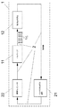
パルス放射線源の放出される放射線を調整する為に、図1に示すように、閉じた制御ループ2が放射線源1で実行される。
In order to adjust the radiation emitted by the pulsed radiation source, a closed control loop 2 is executed at the
ここで従来の特に充電電圧を制御するガス放電駆動の放射線源の調整に対する本質的な違いは、制御ユニット22のインターフェースにある。
Here, the essential difference with respect to the adjustment of the radiation source of the gas discharge drive which controls the charging voltage in particular in the past lies in the interface of the
全ての既知の方法では、制御コンピュータは充電電圧の算出値をプログラム可能な高電圧パルス発生器へ送る。それに対して、放射線源1の放射線発生ユニット12の次のパルスを時間的に遅らせて又は早めて誘起するプログラム可能なトリガー11を始動する為に、本発明に従い、測定ユニット21のアウトプットでのエネルギ測定の結果は、変更されるパルス間隔Δti+1を計算する為、制御ユニット22で利用される。
In all known methods, the control computer sends the calculated charge voltage to a programmable high voltage pulse generator. On the other hand, according to the present invention, at the output of the measuring
図1に従って、制御ループ2は少なくとも以下の構成要素:
a)放射線を感受するセンサ及び測定値を制御コンピュータにより処理可能なデータフォーマットに変換する為の測定値変換器を含む、単独パルスエネルギを測定する為の測定ユニット21、
b)調整アルゴリズムを実行する為の制御ユニット22(制御コンピュータ)、
c)可変で正確な次の単独パルスの誘起を行なうプログラム可能なトリガ発生器11、
d)放射線を放出するプラズマを発生する為の放射線発生ユニット12、例えばガス放電駆動のEUV放射線源1の放電ユニット、及び、
e)放射線源1から測定ユニット21までの光学路、
からなる。
According to FIG. 1, the control loop 2 has at least the following components:
a) a
b) a control unit 22 (control computer) for executing the adjustment algorithm;
c)
d) a
e) an optical path from the
Consists of.
制御ループ2の実施に応じて、選択的に、単独パルスエネルギの測定を、直接放射線源1で行うこと(図1)、又は、放射線源1の外部、例えばリソグラフィ露光システム3(スキャナ)の内部で実行すること(図2)が可能である。その際、測定ユニット21は、その都度ウエハ表面に共役する平面にあり、また、単独の放射線パルスの放出される放射線エネルギを測定する。特に、図2の実施に従い、使用される光学透過システム31及びウエハ表面の影響も考慮され、その際、上記光学透過システムは放射線源1とイメージングされるマスクの間にある。
Depending on the implementation of the control loop 2, the single pulse energy measurement is optionally performed directly at the radiation source 1 (FIG. 1) or outside the
図3は、時間軸上のパルスエネルギの概略図で、調整の基本原理を示す。2つのパルスの間のパルス間隔Δtiは、放射線源1の放射線パルスの所望の平均繰り返し周波数f0から始まり、実際のパルスの放射線エネルギEiの、予め与えられるパルスエネルギの目標値E0からの偏差の大きさに依存して、次のパルスがパルスエネルギEi+1で誘起されるまでに、適応されるパルス間隔Δti+1を計算することにより制御される。
FIG. 3 is a schematic diagram of the pulse energy on the time axis and shows the basic principle of adjustment. The pulse interval Δt i between the two pulses starts from the desired average repetition frequency f 0 of the radiation pulses of the
パルス間隔Δti+1は、現在のパルスのパルスエネルギEiが目標エネルギ値E0をより大きく下回るほどよりいっそう狭まる。又、パルス間隔は、現在のパルスエネルギEiが目標エネルギE0をより大きく上回るほどよりいっそう拡がる。現在のパルスにて目標エネルギE0が維持される場合、パルス間隔は1/f0で所望の平均繰り返し周波数f0に合わせられる。 The pulse interval Δt i + 1 becomes even narrower as the pulse energy E i of the current pulse is much less than the target energy value E 0 . The pulse interval further increases as the current pulse energy E i greatly exceeds the target energy E 0 . If the target energy E 0 is maintained in the current pulse, the pulse interval is 1 / f 0 and is adjusted to the desired average repetition frequency f 0 .
この方法を利用する場合、ウエハ上での到達可能な線量の安定性は露光システム3のいわゆる窓関数(英語:window function)によって決定される。上記窓関数は、どれだけ多くの単独パルスが、全放射線量に対してどれだけ強くウエハの特定の位置に寄与するかを定義し、又、単独パルスの放射線強度の空間分布をスキャン軸w(x−x0)に沿って記載する。定義により、窓関数には次式:
∫w(x−x0)dx=1
が成り立つ。
When using this method, the stability of the reachable dose on the wafer is determined by the so-called window function of the
∫w (x−x 0 ) dx = 1
Holds.
スキャン速度vを介してある時間での関係x=v・tを用いて位置xを変形出来るので、継続的に発光する放射線源とみなされるか、又は、パルス付けられた放射線源とみなされるか、に応じてウエハ上の特定の位置での全放射線量Dは数5で決定される。
ノイズによる線量誤差の正確で統計的な特定は時間がかかり且つ困難であることが判明するので、線量誤差を有利には、本発明に従う方法に従い調整される放射線源1の数的なシミュレーションにより決定することも出来る。
Since accurate and statistical identification of the dose error due to noise proves to be time consuming and difficult, the dose error is advantageously determined by numerical simulation of the
シミュレーションでは先ず、全てのEi及びtiのシーケンス(Folge)が決定され、その後、数5を用いて、この場合に生じる線量D(x)又はD(v・t)はウエハ上の位置に依存して決定される。線量の安定性σDは基準値D0からの線量の平均二乗偏差:
露光線量の精度の為に重要な要因として、用いられる調整アルゴリズムが関与する。有利には上記調整アルゴリズムは、
a)可能な限り高い線量安定性を達成するように、且つ
b)制御ユニット22で可能な限り僅かな演算能力が必要とされるように
選択される。
The adjustment algorithm used is an important factor for the accuracy of the exposure dose. Advantageously, the adjustment algorithm is
It is selected to a) achieve as high a dose stability as possible and b) as little computing power as possible in the
有利には、PIコントローラの簡易型が使用される。上記PIコントローラはその都度次のパルスで、先のパルスの誤差の比較を試みる。その為、調整アルゴリズムの為に以下の数7が与えられる。
それにより、次のパルスへのパルス間隔Δti+1は、線源の所望の平均繰り返し周波数f0、並びに直前のパルスのパルスエネルギEi、及び、単独パルスエネルギ(目標エネルギE0)の為の所望の基準値から、直接獲得できる。 Thereby, the pulse interval Δt i + 1 to the next pulse is due to the desired average repetition frequency f 0 of the source, the pulse energy E i of the previous pulse, and the single pulse energy (target energy E 0 ). Can be obtained directly from the desired reference value.
図3は、本方法がどのようにパルスの時間間隔に作用するかを示す。測定される単独パルスエネルギEiが選択された目標値E0の上にある場合、より小さく放出されたパルスエネルギの場合よりも、次のパルスへの時間間隔Δti+1は大きい結果となる。その際、平均出力:
<Pi>=Ei/Δti+1=E0・f0
は一定に保たれる。
FIG. 3 shows how the method works on the time interval of the pulses. When the measured single pulse energy E i is above the selected target value E 0 , the time interval Δt i + 1 to the next pulse will be larger than in the case of smaller emitted pulse energy. . At that time, average output:
<P i > = E i / Δt i + 1 = E 0 · f 0
Is kept constant.
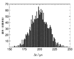
具体的に示す為に、σ=7%のパルス‐パルスエネルギ変動の標準偏差及び5kHz公称周波数f0を有する放射線源1に本方法を適用した。図4はその結果生じるパルス間の時間間隔の分布を示す。
For illustration purposes, the method was applied to a
更に線量精度は、様々な窓関数の為に示される調整の結果として決定され、表1にまとめられている。 In addition, dose accuracy is determined as a result of adjustments shown for various window functions and is summarized in Table 1.
窓関数は、リソグラフィ露光システム3(スキャナ)の特性であり、またスキャン速度に関連するスキャン軸に沿って、ウエハ表面上で、単独パルスの放射線強度の断面に物理的に対応する。x=v・tの関係を介して、ウエハ上の照射されるスポットの幅は、スキャン速度及び2つのパルス間の時間間隔による影響を受ける。その際、用いられる窓関数は単独放射線パルスの強度分布、及び、ウエハ表面上での既定のスキャン移動の際にそれらがどの程度オーバーラップするかを抽象化する。 The window function is a characteristic of the lithographic exposure system 3 (scanner) and physically corresponds to a single pulse radiation intensity cross section on the wafer surface along the scan axis associated with the scan speed. Through the relationship x = v · t, the width of the irradiated spot on the wafer is affected by the scan speed and the time interval between the two pulses. The window function used then abstracts the intensity distribution of the single radiation pulses and how much they overlap during a predetermined scan movement on the wafer surface.
単独パルスの放射線強度が小さい場合(及び/またはウエハ上の光感受性の膜の感度が僅かである)場合、ウエハ上の位置を露光する為に十分に多くの放射パルスが寄与するまで、スキャン速度を減少(及び/またはパルスの公称繰り返し周波数f0を増加)させなければならない。 If the single pulse radiation intensity is small (and / or the sensitivity of the light sensitive film on the wafer is small), the scan speed until a sufficiently large number of radiation pulses contribute to expose a position on the wafer. Must be decreased (and / or the nominal repetition frequency f 0 of the pulse increased).
現在のリソグラフィスキャナ(露光システム3)の場合、数十から数百までのパルスを有する窓関数が一般的である。 In the case of the current lithography scanner (exposure system 3), a window function having tens to hundreds of pulses is common.
ガス放電に基づくEUV放射線源の為には、目下のところ窓の幅は50パルスからが適している。F2レーザやエキシマレーザと連結する場合、より狭い窓関数の窓の幅(30パルスから)で作動可能である。 For EUV radiation sources based on gas discharge, the window width is currently suitable from 50 pulses. When connecting a F 2 laser or an excimer laser is operable in a narrower window function of the window width (30 pulses).
表1に基づくシミュレーションの場合、窓関数の時間幅は全ての状況で正確に50の単独パルス(公称繰り返し周波数f0の場合)のエネルギが全線量に寄与するように、つまり50/f0となるように選択される。
For the simulations according to Table 1, the window function time width is such that the energy of exactly 50 single pulses (for nominal repetition frequency f 0 ) contributes to the total dose in all situations,
窓関数が50パルスの幅を有する場合、2つの互いに続く放射線パルスが、スポットサイズの1/50だけずれて現れる2つの照射される点(スポット)を、ウエハ上に生じることを意味する。 If the window function has a width of 50 pulses, it means that two successive radiation pulses produce on the wafer two irradiated spots (spots) that appear offset by 1/50 of the spot size.
この場合、統計上の理由から、以下の表1の第1行目に様々な窓関数の比較で示されるように、非制御の放射線源では平均化によるのみで既に501/2のファクタの線量安定性の改善、つまりおよそ0.990パーセントの線量安定性が期待される。 In this case, for statistical reasons, an uncontrolled radiation source already has a factor of 50 1/2 only by averaging, as shown in the comparison of various window functions in the first row of Table 1 below. An improvement in dose stability, ie approximately 0.990 percent dose stability is expected.
表1:様々な窓関数の比較
その際、例えばガウス関数、三角関数又は台形関数のような、傾斜した横側を有する窓関数の場合特に、パルス間隔Δti+1を制御することによる調整の利点が効果を発揮することは明らかである。 In that case, it is clear that the advantage of adjustment by controlling the pulse interval Δt i + 1 is particularly effective in the case of a window function having a sloping lateral side, such as a Gaussian function, a trigonometric function or a trapezoidal function. It is.
矩形関数はいずれにせよ現実的な露光関数ではないので、実際の標準的な窓関数の為のパルスの繰り返し周波数の調整は、従来のパルスエネルギの調整方法よりも優れている。それは特に、表1の末行に記載の、近年のスキャナにて優先的に使用される台形関数に当てはまる。 Since the rectangular function is not a realistic exposure function anyway, the adjustment of the pulse repetition frequency for the actual standard window function is superior to the conventional pulse energy adjustment method. This is especially true for the trapezoidal functions described in the last row of Table 1, which are preferentially used in recent scanners.
従来の(比較的単純な調整規則:ES,i+1=E0+ES,i−Eiによる)パルス‐パルスエネルギの安定化との直接的な比較は、パルス間隔Δti+1の調整(矩形窓関数を除く)が比肩しうる結果又は更により良い結果を与えることを証明する。しかしながら、線源位置の変動を回避できないプラズマに基づいた放射線源の為に、それは放射線量を安定化する為の唯一の有効な調節を示す。 A direct comparison with conventional (relatively simple adjustment rule: E S, i + 1 = E 0 + E S, i −E i ) pulse-to-pulse energy stabilization is that of the pulse interval Δt i + 1 Prove that adjustments (except for rectangular window functions) give comparable or even better results. However, for a plasma-based radiation source that cannot avoid source position variations, it represents the only effective adjustment to stabilize the radiation dose.
本発明に従う方法は、プログラミング可能なトリガ11に、次のパルスを誘発する直前においても誘発時点の変更が可能でなければならない、という要求を出す。その為に可能な限り短いリードタイム(Vorlaufzeit)が不可欠であり、上記リードタイムは、次のトリガパルスを時間的に正確に放出出来る前に、トリガ11を内部で必要とする。図5では、このリードタイムはトリガ11の内的なインプットデッド時間tdeadによって特徴付けられる。
The method according to the invention places a requirement on the
時間インターバルtminは2つの放射線パルス間の調節可能な最小の期間を示す。それは、処理時間(放射線パルス、エネルギ測定、適合されるパルス間隔Δti+1の計算、トリガ11のプログラミング)並びに放射線源1の放射線発生ユニット12の最大繰り返し周波数によって定められる。
The time interval t min indicates the minimum adjustable period between two radiation pulses. It is determined by the processing time (radiation pulse, energy measurement, calculation of the adapted pulse interval Δt i + 1 , trigger 11 programming) and the maximum repetition frequency of the
予め選択される平均のパルス間隔Δti=1/f0、すなわち予定される公称パルス周波数f0に従う予め与えられる(放射線発生ユニット12の最適な駆動レジームを調整する為の)パルス間隔Δtiは、パルス間隔Δti+1を短縮することも可能にする為に、常にtminよりも若干大きくなければならない。図5にはこの時間的な関連が表される。 The preselected average pulse interval Δt i = 1 / f 0 , ie a pre-given pulse interval Δt i (to adjust the optimal drive regime of the radiation generating unit 12) according to the expected nominal pulse frequency f 0 is In order to be able to shorten the pulse interval Δt i + 1 , it must always be slightly larger than t min . FIG. 5 shows this temporal relationship.
平均のパルス間隔Δti=1/f0は数8のように定式化されなければならない。
本発明は、挙げられた例では、ガス放電駆動のEUV放射線源との関連で記載されたが、それは同様の方法で同じくパルス駆動されるそれぞれの放射線源、特にEUV源、エキシマレーザ及びF2レーザ、にも適用可能である。 The invention has been described in the context of a given example in the context of a gas discharge driven EUV radiation source, which is also pulsed in a similar manner to each radiation source, in particular an EUV source, excimer laser and F 2. It can also be applied to lasers.
更に本発明は、例において選択されるような、単純な関係Δti+1=Ei/(f0・E0)に限定されるのではなく、それぞれの調整アルゴリズムにも及ぶ。上記調整アルゴリズムは、平均パルスエネルギをパルスエネルギの所望の目標値(期待値)に合わせる為に、測定される単独パルスエネルギ、及び、その他の既知又は測定されるシステム変数から、次の放射線パルスまでの期間を計算する。本発明はつまり、任意の調整関係に適用可能である。上記調節関係では、平均(放射線)出力の目標値は、パルス間隔を変更することで達成される。 Furthermore, the invention is not limited to the simple relationship Δt i + 1 = E i / (f 0 · E 0 ), as selected in the example, but extends to the respective adjustment algorithms. From the measured single pulse energy and other known or measured system variables to the next radiation pulse, the adjustment algorithm adjusts the average pulse energy to the desired target value (expected value) of the pulse energy. Calculate the duration of. That is, the present invention is applicable to any adjustment relationship. In the adjustment relationship, the target value of the average (radiation) output is achieved by changing the pulse interval.
ここで提案される、2つのパルス間の時間的なパルス間隔Δtiにわたる線量の制御を、同様にして、現在のバーストk内で(方程式4に従う)平均放射線出力:
以下で述べられるパルスエネルギ値Ei(k)、Ei(j)は全て、ウエハ平面又は共役面付近で適した手段により測定されるパルスエネルギに関している。 The pulse energy values E i (k), E i (j) described below all relate to pulse energy measured by suitable means near the wafer plane or conjugate plane.
その為に、例えば数10に従うモデルバーストj(又は平均のモデルバースト<j>)から始まる、Δti+1(k)の値が、以下のように計算される。
その際、<Ei(j)>は、平均の非調整のモデルバーストのパルスエネルギ値である(図6の破線で描かれた曲線を参照)。
For this purpose, for example, the value of Δt i + 1 (k), starting from the model burst j (or the average model burst <j>) according to
In this case, <E i (j)> is the pulse energy value of the average unadjusted model burst (see the curve drawn with a broken line in FIG. 6).
モデルバーストjは(一般的にウエハの露光のない)放射線源の個別のキャリブレーティングモード(Kalibriermodus)で露光の為に一般的なバーストパターンで発せられ、そしてそのパルスエネルギ値Ei(j)は保存される。その後、平均パルスエネルギ値<Ei(j)>を計算可能とする為、キャリブレーティングモードを繰り返し実行することが出来る。平均モデルバースト<j>の使用には、実際のパルス間の時間でのパルスエネルギ値も補間することが出来る、そして、十分に高い予測確率で利用出来る、という利点がある。調整されるべき現在のバーストkの為に、合目的に、現在のバーストkのように同一の前歴(Vorgeschichte)(例えば、先のバースト中断の長さ)を有するモデルバーストjが利用される。 The model burst j is emitted in a general burst pattern for exposure in an individual calibration mode (Kalibriermodus) of the radiation source (typically without wafer exposure), and its pulse energy value E i (j) is Saved. Thereafter, the calibration mode can be repeatedly executed so that the average pulse energy value <E i (j)> can be calculated. The use of the average model burst <j> has the advantage that the pulse energy value at the time between actual pulses can also be interpolated and can be used with a sufficiently high prediction probability. For the current burst k to be adjusted, a model burst j with the same Vorgeschichte (eg the length of the previous burst interruption) as the current burst k is used for the purpose.
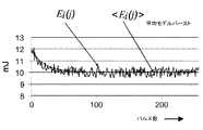
この関係で、ファクタ:<Ei+1(j)>/<Ei(j)>、は多くの場合近似的に1であることに気づかれるべきである。図6の例に従って数11が得られる。
図6aは例示的に、非調整稼動で測定されるモデルバースト(実曲線)、又は、20%のオーバーシュート及び約50パルスのブレイク‐イン‐フェーズ(Einlaufphase)後に調整される変動のない10mJのパルスエネルギを有する平均モデルバースト(破線)を示す。 FIG. 6a exemplarily shows a model burst (solid curve) measured in unregulated operation, or 10 mJ without variation adjusted after 20% overshoot and about 50 pulses of break-in-phase (Einlaufphase). An average model burst (dashed line) with pulse energy is shown.
図6bは、(放射線源1の為に予め選択された5kHzの公称パルス繰り返し周波数f0の場合、)オーバーシュートなしに平均放射線出力<Pi(k)>を得る為の、数10に従いバーストkで計算される、全てのパルス間隔Δti(k)を表す。容易に認識できるように、バースト初期のパルス間隔はオーバーシュートの高さに応じて増加され、また約50パルスの経過で漸次公称パルス周波数f0と適合する。 FIG. 6b shows a burst according to equation 10 to obtain an average radiation output <P i (k)> without overshoot (for a nominal pulse repetition frequency f 0 preselected for radiation source 1). Represents all pulse intervals Δt i (k) calculated by k. As can be easily recognized, the pulse interval at the beginning of the burst is increased with the height of the overshoot, and gradually matches the nominal pulse frequency f 0 in the course of about 50 pulses.
充電電圧はこの進行の際一定を保ち、また、放射線源1が放出条件及び寿命の為の最適なレジームで稼動されるように、また、ウエハ上で要求される放射線量を調整する為の必要な平均パルスエネルギが十分であるように、上記充電電圧は調整される。更に、この場合ガスの供給は、放射線発生ユニット12で最適の放電条件が維持されるように調整される。
The charging voltage remains constant during this process, and is necessary for the
したがって、本発明に従うオーバーシュートを補正する為の調整では、単独パルスエネルギを制御する為の全ての操作変数は、(線源1の長時間稼動の為にそれらは最適に調節されたので)放射線発生ユニット12で一定に保たれる。
Thus, in the adjustment to correct overshoot according to the present invention, all the operating variables for controlling the single pulse energy are radiation (since they have been optimally adjusted for long-term operation of the source 1). The
現在のパルスエネルギEiのその目標値E0からの偏差を補償する為に(つまり初期の約50のオーバーシュートパルスを有する、バーストにおける、一定の平均放射線出力<Pi>を調節する為に)、排他的に、つまり従来のパルスエネルギの調整をせずに、個々のパルス間のパルス間隔Δtiを適応する為の素早い調整プロセスが、つまり順応可能なパルス周波数制御が利用される。 To compensate for the deviation of the current pulse energy E i from its target value E 0 (ie to adjust a constant average radiation output <P i > in a burst with an initial approximately 50 overshoot pulses). ), A rapid adjustment process for adapting the pulse interval Δt i between individual pulses, ie without adapting the conventional pulse energy adjustment, ie adaptable pulse frequency control is used.
E0 単独パルスエネルギの目標値
Ei 現在の単独パルスエネルギ
Δti+1 パルス間隔
f0 公称繰り返し周波数
1 放射線源
3 (リソグラフィ)露光システム
11 トリガ
12 放射線発生ユニット
21 測定ユニット
22 制御ユニット
E 0 Target value of single pulse energy E i Current single pulse energy Δt i + 1 Pulse interval f 0
Claims (20)
‐現在の放射線パルスの単独パルスエネルギ(Ei)を測定するステップ
‐現在の単独パルスエネルギ(Ei)の、予め定められた単独パルスエネルギの目標値(E0)からの偏差ΔE=Ei−E0を決定するステップ、及び
‐現在の単独パルスエネルギ(Ei)の、パルスエネルギの目標値(E0)からの偏差の大きさに依存して、次の放射線パルスを誘起するまでのパルス間隔(Δti+1)を制御するステップ、
を特徴とする方法。 In a method for stabilizing the average output of the emitted radiation of a pulsed radiation source, in particular by an EUV radiation source based on excimer laser, F 2 laser or high temperature plasma, the following steps:
The step of measuring the single pulse energy (E i ) of the current radiation pulse, the deviation ΔE = E i of the current single pulse energy (E i ) from the target value (E 0 ) of the predetermined single pulse energy determining -E 0, and - the current individual pulse energy of (E i), depending on the magnitude of the deviation from the target value of pulse energy (E 0), to induce the next radiation pulse Controlling the pulse interval (Δt i + 1 );
A method characterized by.
‐単独パルスの平均繰り返し周波数(f0)、
‐パルスエネルギ(E0)の要求される目標値、及び
‐現在のパルスの測定される単独パルスエネルギ(Ei)
から、計算規則Δti+1=Ei/(f0・E0)を用いて決定されることを特徴とする方法。 The method according to claim 1, wherein the pulse interval (Δt i +1 ) is-the average repetition frequency (f 0 ) of a single pulse,
The required target value of the pulse energy (E 0 ), and the measured single pulse energy (E i ) of the current pulse.
The method is characterized in that it is determined using the calculation rule Δt i + 1 = E i / (f 0 · E 0 ).
∫w(x−x0)dx=1
と定義され、その際位置xはスキャン速度v及び時間tの積により置き換えられ、又、全線量Dがウエハ上の特定の位置で、
D=∫w(v・t−v・t0)P(t)dt
=Σw(v・ti−v・t0)Ei
に対して計算されることを特徴とする方法。 5. The method according to claim 4, wherein the window function is ∫w (x−x 0 ) dx = 1 from the spatial distribution of the radiation intensity of a single pulse with respect to the scan axis w (x−x 0 ).
Where x is replaced by the product of scan speed v and time t, and the total dose D is at a specific position on the wafer,
D = ∫w (v · t−v · t 0 ) P (t) dt
= Σw (v · t i −v · t 0 ) E i
A method characterized by being computed for.
Δti+1(k)=(1/f0)・(Ei(k)/E0)・(<Ei+1(j)>/<Ei(j)>)
に従う次のパルスに対するパルス間隔が算出され、その際平均パルスエネルギ値(<Ei(j)>)として、少なくとも非調整のモデルバースト(j)のパルスエネルギ値(Ei(j))が用いられることを特徴とする方法。 10. The method according to claim 9, wherein the relation Δt i + 1 (k) = (1 / f 0 ) · (E i (k) / E 0 ) · (<E i + 1 (j)> / <E i (j)>)
The pulse interval for the next pulse in accordance with is calculated, using at least the pulse energy value (E i (j)) of the unadjusted model burst (j) as the average pulse energy value (<E i (j)>). The method characterized by being made.
‐パルス間隔を調整するための制御ユニット(22)が備えられ、
上記制御ユニットは現在のパルスのパルスエネルギを測定する為の測定ユニット(21)と接続され、また上記制御ユニットはアウトプットにて制御信号を有し、上記制御信号は、現在のパルスの測定される単独パルスエネルギ(Ei)の、パルスエネルギ(E0)の所望の目標値からの偏差に基づいて発せられ、また、現在のパルスに対する次のパルスのパルス間隔(Δti+1)の基準値の為の大きさを表すこと、及び
‐パルス誘起時点を素早く変更するためのプログラム可能なトリガ(11)が、制御ユニット(22)及び放射線発生ユニット(12)の間に配設され、上記トリガによって次のパルスの誘起時点は制御ユニット(22)の出力信号に依存して単独パルスの公称繰り返し周波数(f0)に対して変更可能であること
を特徴とする装置。 In particular excimer laser, F 2 laser, or by EUV radiation sources based on high temperature pulse, in the apparatus for stabilizing the average output of the radiation of the radiation source is pulsed to generate a radiation pulse of high pulse repetition frequency Control of the radiation generation unit, the measurement unit for measuring the pulse energy of each individual pulse, and the action variable of the radiation generation unit enabling the control of the next pulse based on the pulse energy measurement of at least one preceding pulse In a device including a closed control loop for
A control unit (22) for adjusting the pulse interval is provided,
The control unit is connected to a measurement unit (21) for measuring the pulse energy of the current pulse, and the control unit has a control signal at the output, the control signal being measured for the current pulse. A single pulse energy (E i ) based on a deviation from a desired target value of the pulse energy (E 0 ), and a reference for the pulse interval (Δt i + 1 ) of the next pulse relative to the current pulse A programmable trigger (11) for representing the magnitude for the value and for quickly changing the pulse induction time is arranged between the control unit (22) and the radiation generation unit (12), wherein the induction time of the next by a trigger pulse can be changed for a nominal repetition frequency of the individual pulse in dependence on the output signal of the control unit (22) (f 0) Device that.
Applications Claiming Priority (1)
| Application Number | Priority Date | Filing Date | Title |
|---|---|---|---|
| DE102006060368A DE102006060368B3 (en) | 2006-12-16 | 2006-12-16 | Method and arrangement for stabilizing the mean emitted radiation power of a pulsed operated radiation source |
Publications (2)
| Publication Number | Publication Date |
|---|---|
| JP2008153645A true JP2008153645A (en) | 2008-07-03 |
| JP2008153645A5 JP2008153645A5 (en) | 2009-03-19 |
Family
ID=39526726
Family Applications (1)
| Application Number | Title | Priority Date | Filing Date |
|---|---|---|---|
| JP2007305689A Pending JP2008153645A (en) | 2006-12-16 | 2007-11-27 | Method and unit for stabilizing output average of radiation emitted from pulsed radioactive source |
Country Status (4)
| Country | Link |
|---|---|
| US (1) | US7974321B2 (en) |
| JP (1) | JP2008153645A (en) |
| DE (1) | DE102006060368B3 (en) |
| NL (1) | NL2001094C2 (en) |
Cited By (1)
| Publication number | Priority date | Publication date | Assignee | Title |
|---|---|---|---|---|
| JP2018533755A (en) * | 2015-10-27 | 2018-11-15 | サイマー リミテッド ライアビリティ カンパニー | Controller for optical system |
Families Citing this family (4)
| Publication number | Priority date | Publication date | Assignee | Title |
|---|---|---|---|---|
| KR101698141B1 (en) * | 2009-12-08 | 2017-01-19 | 삼성전자 주식회사 | Maskless exposure apparatus and control method thereof |
| US9823572B2 (en) * | 2013-06-18 | 2017-11-21 | Asml Netherlands B.V. | Lithographic method |
| DE102016212928B3 (en) * | 2016-07-14 | 2017-09-07 | Trumpf Laser Gmbh | Method for generating a laser pulse and arrangement for generating a driver drive signal |
| JP2022059163A (en) | 2020-10-01 | 2022-04-13 | ギガフォトン株式会社 | Extreme-ultraviolet light generation system, and manufacturing method of electronic device |
Family Cites Families (21)
| Publication number | Priority date | Publication date | Assignee | Title |
|---|---|---|---|---|
| US582621A (en) * | 1897-05-18 | Combined churn and butter-worker | ||
| US3747019A (en) * | 1970-07-16 | 1973-07-17 | Union Carbide Corp | Method and means for stabilizing the amplitude and repetition frequency of a repetitively q-switched laser |
| US4804978A (en) * | 1988-02-19 | 1989-02-14 | The Perkin-Elmer Corporation | Exposure control system for full field photolithography using pulsed sources |
| JPH02177313A (en) * | 1988-12-28 | 1990-07-10 | Canon Inc | Exposure controller |
| JP3235078B2 (en) * | 1993-02-24 | 2001-12-04 | 株式会社ニコン | Scanning exposure method, exposure control device, scanning type exposure device, and device manufacturing method |
| JP3296448B2 (en) * | 1993-03-15 | 2002-07-02 | 株式会社ニコン | Exposure control method, scanning exposure method, exposure control apparatus, and device manufacturing method |
| JPH07254559A (en) * | 1994-01-26 | 1995-10-03 | Canon Inc | Scanning type aligner and device production method using the same |
| JP3451604B2 (en) * | 1994-06-17 | 2003-09-29 | 株式会社ニコン | Scanning exposure equipment |
| US5632739A (en) * | 1994-10-13 | 1997-05-27 | The General Hospital Corporation | Two-pulse, lateral tissue illuminator |
| JPH09190966A (en) | 1996-01-08 | 1997-07-22 | Canon Inc | Scan type exposure system and manufacture of device using it |
| KR100210569B1 (en) | 1995-09-29 | 1999-07-15 | 미따라이 하지메 | Exposure method and exposure apparatus and method for manufacturing device using the same |
| JP3813635B2 (en) * | 1996-04-01 | 2006-08-23 | エイエスエムエル ネザランドズ ベスローテン フエンノートシャップ | Lithographic scanning exposure projection apparatus |
| US6538723B2 (en) * | 1996-08-05 | 2003-03-25 | Nikon Corporation | Scanning exposure in which an object and pulsed light are moved relatively, exposing a substrate by projecting a pattern on a mask onto the substrate with pulsed light from a light source, light sources therefor, and methods of manufacturing |
| US5982800A (en) * | 1997-04-23 | 1999-11-09 | Cymer, Inc. | Narrow band excimer laser |
| US5852621A (en) * | 1997-07-21 | 1998-12-22 | Cymer, Inc. | Pulse laser with pulse energy trimmer |
| TW448487B (en) * | 1997-11-22 | 2001-08-01 | Nippon Kogaku Kk | Exposure apparatus, exposure method and manufacturing method of device |
| JP3807933B2 (en) * | 2000-12-14 | 2006-08-09 | 株式会社ルネサステクノロジ | Projection exposure apparatus and projection exposure method |
| DE10209161B4 (en) * | 2002-02-26 | 2009-09-17 | Xtreme Technologies Gmbh | Method for regulating the energy of pulsed gas-discharge-pumped radiation sources |
| DE10244105B3 (en) * | 2002-02-26 | 2004-09-16 | Xtreme Technologies Gmbh | Process for energy stabilization of gas discharge pumped radiation sources operated in defined pulse sequences |
| DE10219805B4 (en) * | 2002-04-30 | 2013-03-14 | Xtreme Technologies Gmbh | A method for stabilizing the radiant power of a pumped gas-generated plasma source |
| FR2859545B1 (en) | 2003-09-05 | 2005-11-11 | Commissariat Energie Atomique | METHOD AND DEVICE FOR RADIATION LITHOGRAPHY IN THE EXTREME UTRAVIOLET |
-
2006
- 2006-12-16 DE DE102006060368A patent/DE102006060368B3/en active Active
-
2007
- 2007-11-27 JP JP2007305689A patent/JP2008153645A/en active Pending
- 2007-12-04 US US11/949,924 patent/US7974321B2/en active Active
- 2007-12-14 NL NL2001094A patent/NL2001094C2/en active Search and Examination
Cited By (1)
| Publication number | Priority date | Publication date | Assignee | Title |
|---|---|---|---|---|
| JP2018533755A (en) * | 2015-10-27 | 2018-11-15 | サイマー リミテッド ライアビリティ カンパニー | Controller for optical system |
Also Published As
| Publication number | Publication date |
|---|---|
| US7974321B2 (en) | 2011-07-05 |
| NL2001094A1 (en) | 2008-06-17 |
| DE102006060368B3 (en) | 2008-07-31 |
| US20080143989A1 (en) | 2008-06-19 |
| NL2001094C2 (en) | 2011-01-31 |
Similar Documents
| Publication | Publication Date | Title |
|---|---|---|
| JP6985338B2 (en) | Wavelength stabilization for light source | |
| US5250797A (en) | Exposure method and apparatus for controlling light pulse emission using determined exposure quantities and control parameters | |
| JP6782775B2 (en) | Online calibration of iteration-dependent performance variables | |
| KR102071965B1 (en) | Active spectral control during spectrum synthesis | |
| JP2003332233A (en) | Lithographic system, method of manufacturing device, method of measuring performance, method for calibration, and computer program | |
| KR102213153B1 (en) | How to adjust the amount of coherence of the light beam | |
| JP2008153645A (en) | Method and unit for stabilizing output average of radiation emitted from pulsed radioactive source | |
| KR101564391B1 (en) | System and method for compensating for thermal effects in an euv light source | |
| JP2902172B2 (en) | Exposure equipment | |
| US10627724B2 (en) | Lithographic apparatus and method | |
| JP2008153645A5 (en) | ||
| JP2785157B2 (en) | Light intensity control device and exposure device | |
| JP7430799B2 (en) | Control system for light sources | |
| US20220163895A1 (en) | Method for Controlling a Lithographic System | |
| JP2963692B2 (en) | Laser irradiation stepper or scanner with energy sensor feedback | |
| JP2006518098A (en) | Timing control of electromagnetic radiation pulses | |
| TWI642914B (en) | Methods of controlling an optical source in a photolithography system and a photolithography system | |
| JP2004006336A (en) | Method for stabilizing radiation output in radioactive source of pulse-driven gas discharge linking type | |
| KR20230042590A (en) | Predictive Calibration Scheduling Apparatus and Method | |
| CN117441133A (en) | Forming multiple aerial images in a single lithographic exposure pass | |
| JP2023507070A (en) | Energy correction module for light sources | |
| JP2000021717A (en) | Exposure control method and aligner | |
| JPH0969492A (en) | Lighting method, exposure method and exposure system thereby | |
| JP2006019561A (en) | Exposure method | |
| JP2012099766A (en) | Exposure device and exposure amount control method therefor |
Legal Events
| Date | Code | Title | Description |
|---|---|---|---|
| A521 | Request for written amendment filed |
Free format text: JAPANESE INTERMEDIATE CODE: A523 Effective date: 20090203 |
|
| A621 | Written request for application examination |
Free format text: JAPANESE INTERMEDIATE CODE: A621 Effective date: 20090203 |
|
| A871 | Explanation of circumstances concerning accelerated examination |
Free format text: JAPANESE INTERMEDIATE CODE: A871 Effective date: 20090203 |
|
| A975 | Report on accelerated examination |
Free format text: JAPANESE INTERMEDIATE CODE: A971005 Effective date: 20090225 |
|
| A131 | Notification of reasons for refusal |
Free format text: JAPANESE INTERMEDIATE CODE: A131 Effective date: 20090407 |
|
| A601 | Written request for extension of time |
Free format text: JAPANESE INTERMEDIATE CODE: A601 Effective date: 20090707 |
|
| A602 | Written permission of extension of time |
Free format text: JAPANESE INTERMEDIATE CODE: A602 Effective date: 20090710 |
|
| A521 | Request for written amendment filed |
Free format text: JAPANESE INTERMEDIATE CODE: A523 Effective date: 20090805 |
|
| A02 | Decision of refusal |
Free format text: JAPANESE INTERMEDIATE CODE: A02 Effective date: 20091208 |