JP2008148564A - Tillage tine-attaching structure - Google Patents

Tillage tine-attaching structure Download PDF

Info

Publication number
JP2008148564A
JP2008148564A JP2006336698A JP2006336698A JP2008148564A JP 2008148564 A JP2008148564 A JP 2008148564A JP 2006336698 A JP2006336698 A JP 2006336698A JP 2006336698 A JP2006336698 A JP 2006336698A JP 2008148564 A JP2008148564 A JP 2008148564A
Authority
JP
Japan
Prior art keywords
claw
tilling
holder
tillage
nail
Prior art date
Legal status (The legal status is an assumption and is not a legal conclusion. Google has not performed a legal analysis and makes no representation as to the accuracy of the status listed.)
Pending
Application number
JP2006336698A
Other languages
Japanese (ja)
Inventor
Toru Yamada
通 山田
Current Assignee (The listed assignees may be inaccurate. Google has not performed a legal analysis and makes no representation or warranty as to the accuracy of the list.)
Individual
Original Assignee
Individual
Priority date (The priority date is an assumption and is not a legal conclusion. Google has not performed a legal analysis and makes no representation as to the accuracy of the date listed.)
Filing date
Publication date
Application filed by Individual filed Critical Individual
Priority to JP2006336698A priority Critical patent/JP2008148564A/en
Publication of JP2008148564A publication Critical patent/JP2008148564A/en
Pending legal-status Critical Current

Links

Images

Landscapes

  • Soil Working Implements (AREA)

Abstract

<P>PROBLEM TO BE SOLVED: To provide a tillage tine-attaching structure which has durability, can retain a stable binding state, and facilitates works for attaching or detaching the tillage tines. <P>SOLUTION: This tillage tine-attaching structure for inserting the base portion 1a of a tillage tine 1 into the hole 3 of a holder 2 to hold the tillage tine 1 is characterized in that the holder 2 has bracket portions 4, 5 extended in the right and left directions, respectively, to place the base portion 1a of the tillage tine 1 between the bracket portions 4, 5 on both the sides. <P>COPYRIGHT: (C)2008,JPO&INPIT

Description

この発明は、耕耘用作業機の耕耘軸における耕耘爪取り付け構造に関するものである。   The present invention relates to a tilling claw attachment structure on a tilling shaft of a tilling work machine.

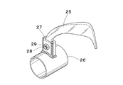
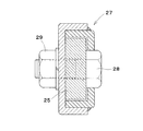
従来、ロータリ耕耘機の耕耘軸における耕耘爪取り付け構造として、特許文献1に記載のようなホルダ方式がある。このホルダ方式では、図9、図10に示したように、耕耘爪25を耕耘軸26に溶接された前壁側の爪保持体と背壁側の爪カバー体からなるホルダ27の穴に挿入し、耕耘爪25とホルダ27それぞれに設けたボルト挿通孔に通した1組のボルト28とナット29により締め付け固定するようにしたものが一般的である。   2. Description of the Related Art Conventionally, there is a holder system as described in Patent Document 1 as a tilling claw attachment structure on a tilling shaft of a rotary tiller. In this holder system, as shown in FIGS. 9 and 10, the tilling claw 25 is inserted into the hole of the holder 27 composed of the front wall side claw holding body and the back wall side claw cover body welded to the tilling shaft 26. In general, the bolts are clamped and fixed by a set of bolts 28 and nuts 29 that are passed through bolt insertion holes provided in the tilling claws 25 and the holder 27, respectively.

このホルダ方式では、前記ボルト28とナット29の締め付けにより、耕耘爪25とホルダ27とが摩擦接合されるのであるが、耕耘軸26の回転や外力により大きな負荷がかかると、ホルダ27が変形したり、耕耘軸26が陥没変形したりすることがある。   In this holder system, the tillage claw 25 and the holder 27 are frictionally joined by tightening the bolt 28 and the nut 29. However, when a large load is applied by the rotation of the tillage shaft 26 or an external force, the holder 27 is deformed. Or the tilling shaft 26 may be deformed.

また、別の従来の耕耘爪取り付け構造として、フランジ方式がある。図11に示したように、フランジ方式では、耕耘軸26の周囲に設けたフランジ30に、複数の耕耘爪25をそれぞれボルト28とナット29により締め付け固定する。   As another conventional tillage claw attachment structure, there is a flange system. As shown in FIG. 11, in the flange method, a plurality of tilling claws 25 are fastened and fixed to a flange 30 provided around the tilling shaft 26 by bolts 28 and nuts 29, respectively.

このフランジ方式では、耕耘爪25を一枚の平鋼板であるフランジ30に直接締結するため製造が容易である。しかし、図12に示すように、当初、耕耘爪25は摩擦接合によりフランジ30に強く保持されていても、急激な負荷の変動や振動、あるいは耕耘爪25やフランジ30にかかる図中左右方向の負荷W1,W2、これらと直角に働く負荷、及び捩り負荷によって生じるボルト28・ナット29の緩め作用によって、接合面の摩擦力は次第に減少する。この場合、ボルト28のせん断応力Cによって摩擦力を補填するはずであるが、実際には、せん断応力によって摩擦力を十分に補填できる程度に、耕耘爪25、フランジ30ともに面仕上げすることや、ボルト孔とボルト軸部の嵌合精度を良くすることは不可能である。そのため、この部位にはせん断応力の代わりに、圧縮や引張の複雑な応力が発生して塑性変形が始まり、締結力が減衰し、これによって疲労破壊が起こることになる。   In this flange system, the tilling claw 25 is directly fastened to the flange 30 which is a single flat steel plate, so that the manufacture is easy. However, as shown in FIG. 12, initially, even if the tilling claw 25 is strongly held by the flange 30 by friction bonding, a sudden load fluctuation or vibration, or the tilling claw 25 or the flange 30 in the horizontal direction in the figure is applied. Due to the loads W1 and W2, loads acting at right angles to these, and the loosening action of the bolts 28 and nuts 29 caused by the torsional load, the frictional force of the joint surface gradually decreases. In this case, the frictional force should be compensated by the shear stress C of the bolt 28, but actually, the tilling claws 25 and the flange 30 are both finished to the extent that the frictional force can be sufficiently compensated by the shearing stress, It is impossible to improve the fitting accuracy between the bolt hole and the bolt shaft portion. For this reason, instead of shear stress, complex stress such as compression or tension is generated at this portion, plastic deformation starts, and the fastening force is attenuated, thereby causing fatigue failure.

また、フランジ方式では、フランジ30の厚みに関する中心線31と、耕耘爪25の同中心線32が大きく離れており、耕耘爪25とフランジ30の各ボルト孔とボルト28との嵌合における接合点が、上記中心線31,32の間隔以上に離れる可能性が高い。この場合には、前記左右方向の負荷W1,W2によってボルト28に折り曲げ作用が働き、せん断応力C以外の応力が増加することになり、耐久性を向上させるような合理的な応力を発生させることは難しく、耐久性に悪影響をもたらす。このために各部材の強度を上げざるを得なくなり、これによって重量が嵩むものとなってしまう。   Further, in the flange method, the center line 31 relating to the thickness of the flange 30 and the center line 32 of the tilling claw 25 are greatly separated from each other. However, there is a high possibility that the distance between the center lines 31 and 32 is more than the distance. In this case, the bolts 28 are bent by the loads W1 and W2 in the left and right directions, and stresses other than the shear stress C increase, so that a reasonable stress that improves durability is generated. Is difficult and adversely affects durability. For this reason, the strength of each member must be increased, which increases the weight.

さらに、フランジ方式では、1つの耕耘爪25の取り付けのために少なくとも2組のボルトとナットが必要で、全体では多くのボルトとナットが必要になるため、耕耘爪25の取り付けや取り外しの作業に多くの時間と労力が必要であり、作業者に大きな負担となっていた。
実開平1−60606号公報
Furthermore, in the flange method, at least two pairs of bolts and nuts are required for attaching one tilling claw 25, and many bolts and nuts are required as a whole. It took a lot of time and effort, which was a heavy burden on the workers.
Japanese Utility Model Publication No. 1-60606

そこで、この発明は、従来よりも、耐久性があり、安定した接合状態を保つことが可能で、しかも、耕耘爪の取り付けや取り外しの作業が容易な耕耘爪取り付け構造を提供することを課題とする。   Therefore, the present invention has an object to provide a tillage claw attachment structure that is more durable and can maintain a stable joining state than before, and that can be easily attached and removed. To do.

前記課題を解決するため、この発明は次のような技術的手段を講じている。   In order to solve the above problems, the present invention takes the following technical means.

この発明の耕耘爪取り付け構造は、耕耘爪1の基部1aをホルダ2の穴3に挿入して耕耘爪1を保持するようにした耕耘爪取り付け構造であって、ホルダ2は左右両側にそれぞれ左右方向に延びるブラケット部4,5を有しており、両側のブラケット部4,5間に耕耘爪1の基部1aが位置するようにしたものとしている。   The tillage claw attachment structure of the present invention is a tillage claw attachment structure in which the base 1a of the tillage claw 1 is inserted into the hole 3 of the holder 2 so as to hold the tillage claw 1, and the holder 2 has left and right sides respectively. It has bracket portions 4 and 5 extending in the direction, and the base portion 1a of the tilling claw 1 is positioned between the bracket portions 4 and 5 on both sides.

耕耘爪1の基部1aの厚みの中心線6と、両側のブラケット部4,5の厚みの中心線7が、略一直線状となるようにしたものとすることができる。   The center line 6 of the thickness of the base portion 1a of the tilling claw 1 and the center lines 7 of the thicknesses of the bracket portions 4 and 5 on both sides can be made substantially straight.

耕耘爪1の基部1aとホルダ2にそれぞれボルト挿通孔8,9,10を設け、1組のボルト11とナット12で締め付け固定するようにしたものとすることができる。   Bolt insertion holes 8, 9, 10 can be provided in the base 1 a of the tilling claw 1 and the holder 2, respectively, and can be fastened and fixed with a set of bolts 11 and nuts 12.

また、ブラケット部4,5が、耕耘軸13の周囲に設けられた板14の一部として構成されているものとすることができる。   Moreover, the bracket parts 4 and 5 shall be comprised as a part of board 14 provided around the tilling shaft 13.

この発明の耕耘爪取り付け構造は、上述のような構成を有しており、ホルダ2の両側のブラケット部4,5間に耕耘爪1の基部1aが位置するようになっているが、耕耘爪1にかかる主たる負荷は、耕耘爪1の回転による耕耘作業時に加わる土壌からの耕耘抵抗であるから、この抵抗力は、耕耘爪1の基部1aからストレートにこれと接触する受圧側のホルダ2の側部、さらにブラケット部4,5に伝わることとなり、そしてホルダ2の側部に発生する耐圧力や、ブラケット部4,5が側部を支える力と均衡するため、耕耘爪1とホルダ2との安定した接合状態を保つことが可能である。   The tillage claw attachment structure of the present invention has the above-described configuration, and the base 1a of the tillage claw 1 is positioned between the bracket portions 4 and 5 on both sides of the holder 2. Since the main load applied to 1 is a tilling resistance from the soil applied during the tilling work by the rotation of the tilling claw 1, this resistance force is applied to the pressure-receiving side holder 2 in direct contact with the base 1 a of the tilling claw 1. Since the pressure resistance generated on the side part of the holder 2 and the side part of the holder 2 and the force with which the bracket parts 4 and 5 support the side part are balanced, the tillage claw 1 and the holder 2 It is possible to maintain a stable bonding state.

しかも、1組のボルト11とナット12で締め付け固定するようにすれば、耕耘爪1の取り付けや取り外しの作業を容易にすることも可能である。   Moreover, if the bolt 11 and the nut 12 are tightened and fixed, the work of attaching and removing the tilling claw 1 can be facilitated.

以下、この発明の好適な実施形態を、図面を参照して説明する。   Preferred embodiments of the present invention will be described below with reference to the drawings.

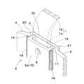
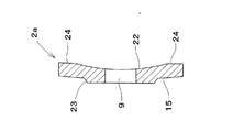
図1はこの発明の実施形態の耕耘爪取り付け構造の要部の断面図、図2はこの取り付け構造の説明図である。   FIG. 1 is a cross-sectional view of a main part of a tillage claw attachment structure according to an embodiment of the present invention, and FIG. 2 is an explanatory view of the attachment structure.

この耕耘爪取り付け構造は、耕耘爪1の基部1aをホルダ2の穴3に挿入して耕耘爪1を保持するようにした耕耘爪取り付け構造であって、ホルダ2は左右両側にそれぞれ左右方向に延びるブラケット部4,5を有しており、両側のブラケット部4,5間に耕耘爪1の基部1aが位置するようにしている。   This tillage nail attachment structure is a tillage nail attachment structure in which the base 1a of the tillage nail 1 is inserted into the hole 3 of the holder 2 so as to hold the tillage nail 1, and the holder 2 is arranged on the left and right sides respectively in the left and right direction. It has the bracket parts 4 and 5 extended, and the base 1a of the tilling claw 1 is located between the bracket parts 4 and 5 on both sides.

以下、この耕耘爪取り付け構造をブラケット方式と呼ぶことにする。また、耕耘爪1の基部1aの幅方向を左右方向とする。両側のブラケット部4,5間に耕耘爪1の基部1aが位置することは、両側のブラケット部4,5を結ぶ直線を観念した場合、耕耘爪1の基部1aが前記直線をさえぎるように位置することとなる関係にあることを意味する。耕耘爪1の基部1aは、その厚みに関する中心線6が、図1に示したように、両側のブラケット部4,5の同中心線7と一直線状になることが望ましいが、特にその態様に限定されず、前後方向にずれていても良い。   Hereinafter, this tilling claw attachment structure is referred to as a bracket system. Moreover, let the width direction of the base 1a of the tilling nail 1 be the left-right direction. The position of the base 1a of the tilling claw 1 between the bracket parts 4 and 5 on both sides is such that when the straight line connecting the bracket parts 4 and 5 on both sides is considered, the base 1a of the tilling claw 1 blocks the straight line. It means that there is a relationship that will be. As for the base 1a of the tilling nail 1, it is desirable that the center line 6 relating to its thickness is aligned with the same center line 7 of the bracket parts 4 and 5 on both sides as shown in FIG. It is not limited, You may shift | deviate in the front-back direction.

ブラケット方式において、耕耘爪1は従来のものと同様とすることができる。具体的には、耕耘爪1は、適材に熱処理を施して高強度の弾性体に仕上げられており、基部1aと刃部1bとから構成され、基部1aの中央部にはボルト挿通孔8が設けられたものとすることができる。基部1aは、図1に示したように、断面が左右方向に長い長方形状としている。   In the bracket system, the tilling claw 1 can be the same as the conventional one. Specifically, the tilling claw 1 is heat-treated to an appropriate material and finished to a high-strength elastic body, and is composed of a base portion 1a and a blade portion 1b. A bolt insertion hole 8 is formed in the central portion of the base portion 1a. It can be provided. As shown in FIG. 1, the base 1a has a rectangular shape with a long cross section in the left-right direction.

ホルダ2は、爪保持体2aと爪カバー体2bとから構成され、爪保持体2aと爪カバー体2bの内側にできた穴3に耕耘爪1の基部1aが挿入されるようにしている。   The holder 2 includes a claw holder 2a and a claw cover body 2b, and the base 1a of the tilling claw 1 is inserted into a hole 3 formed inside the claw holder 2a and the claw cover body 2b.

爪保持体2aは、略正方形の板状の中央部15とその両側の側部16,17からなる断面略コ字状で、上端の開口部から耕耘爪1の基部1aが挿入され、円弧状に凹んだ底部が耕耘軸13の外周面に固着されるようにしている。爪保持体2aの中央部15には、ボルト挿通孔9が設けられている。爪保持体2aは、高い弾性を有する適材(例えば、ばね鋼)で形成されており、耕耘軸13の外周面に放射状となるように適宜間隔で複数個、溶接等の手段により固着される。   The claw holding body 2a has a substantially square plate-shaped central portion 15 and side portions 16 and 17 on both sides thereof, and has a substantially circular U-shaped cross section. The bottom that is recessed is fixed to the outer peripheral surface of the tilling shaft 13. A bolt insertion hole 9 is provided in the central portion 15 of the claw holder 2a. The claw holder 2a is made of a suitable material having high elasticity (for example, spring steel), and a plurality of claw holders 2a are fixed to the outer peripheral surface of the tilling shaft 13 at appropriate intervals by means such as welding.

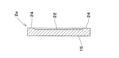
爪カバー体2bは、1枚の平鋼板の一部を断面略コ字状とすることにより凹部19を形成し、これに爪保持体2aを嵌合させるようにしたものである。凹部19の左右両側の側部20,21は、爪保持体2aの両側の側部16,17に外側から接するようにしている。凹部19の外側に張り出した部分がホルダ2のブラケット部4,5となる。   The claw cover body 2b is formed by forming a concave portion 19 by fitting a part of one flat steel plate into a substantially U-shaped cross section and fitting the claw holding body 2a thereto. The left and right side portions 20 and 21 of the recess 19 are in contact with the side portions 16 and 17 on both sides of the claw holder 2a from the outside. The portions projecting outside the recess 19 become the bracket portions 4 and 5 of the holder 2.

爪カバー体2bの材質は、低炭素鋼でよいが、必要に応じて爪保持体2aと同じものとすることができる。また、爪保持体2aと爪カバー体2bとの間に溶接箇所18を設けて両者を固定し、一体化したホルダとすることができる。   The material of the claw cover body 2b may be low carbon steel, but can be the same as that of the claw holder 2a as required. Moreover, the welding location 18 is provided between the nail | claw holding | maintenance body 2a and the nail | claw cover body 2b, both can be fixed, and it can be set as the integrated holder.

ブラケット部4,5は、それぞれ前後方向に関して同じ位置から、左右方向に直線的に一様の厚みで延びたものとしており、両ブラケット4,5の互いの前面、後面がそれぞれ同一平面上に位置するような関係となっている。爪カバー体2bは、ブラケット部4,5を、溶接等により耕耘軸13に設けた板状の固定部に固着することができる。   The bracket portions 4 and 5 extend from the same position in the front-rear direction to the left and right directions with a uniform thickness, and the front and rear surfaces of the brackets 4 and 5 are located on the same plane. It has become a relationship. The claw cover body 2b can fix the bracket portions 4 and 5 to a plate-like fixing portion provided on the tilling shaft 13 by welding or the like.

凹部19の中央部には、前記爪保持体2aのボルト挿通孔9に対応するボルト挿通孔10が設けられている。凹部19と爪保持体2aとは、互いの内面が向き合うように組み合わされてホルダ2を構成し、このホルダ2内に耕耘爪1の基部1aを挿入し、そして、各ボルト挿通孔8,9,10に通したボルト11と、爪保持体2aの外面側に配置されたナット12とにより、締め付けるようにしている。   A bolt insertion hole 10 corresponding to the bolt insertion hole 9 of the claw holder 2a is provided at the center of the recess 19. The concave portion 19 and the claw holder 2a are combined so that the inner surfaces thereof face each other to constitute the holder 2, the base 1a of the tilling claw 1 is inserted into the holder 2, and the bolt insertion holes 8, 9 , 10 and a nut 12 disposed on the outer surface side of the claw holder 2a.

前記爪保持体2aと爪カバー体2bとの溶接箇所18や、爪保持体2a、爪カバー体2bやブラケット部4,5と耕耘軸13との溶接箇所は、強度や耐久性の観点から必要な部位に設ければよい。溶接熱による硬度や強度の低下を招くと具合の悪い部位(例えば、ホルダ2の弾性強度を必要とする部位)には、レーザ溶接を行うとよい。   The welded portion 18 between the claw holding body 2a and the claw cover body 2b and the welded portion between the claw holding body 2a, the claw cover body 2b, the bracket portions 4, 5 and the tillage shaft 13 are necessary from the viewpoint of strength and durability. What is necessary is just to provide in a site | part. When the hardness and strength are reduced by welding heat, laser welding may be performed on a portion that is not good (for example, a portion that requires the elastic strength of the holder 2).

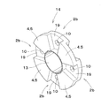
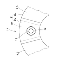
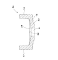
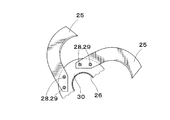
爪カバー体2bは、図3、図4に示したように、耕耘軸13の周面に取り付けられたドーナツ状の板14の一部を構成するものとすることができる。図示した例では、前記板14の片面に、4つの凹部19が等間隔で形成され、各凹部19に爪保持体2aが取り付けられることにより、4つのホルダ2が構成されるようになっている。各凹部19と爪保持体2aは略扇形となっているが、図示した通りの形状に限定されず、矩形や扇形が変形した形状(例えば、耕耘軸13側に長方形や上下反転した小さな扇形を付け足したような形状)等とすることもできる。ボルト挿通孔9,10の位置は、凹部19と爪保持体2aの形状や大きさに応じて、適宜設定することができる。   As shown in FIGS. 3 and 4, the claw cover body 2 b can constitute a part of the donut-shaped plate 14 attached to the peripheral surface of the tilling shaft 13. In the illustrated example, four concave portions 19 are formed at equal intervals on one side of the plate 14, and the four holders 2 are configured by attaching the claw holders 2 a to the concave portions 19. . Each concave portion 19 and the claw holder 2a are substantially fan-shaped, but are not limited to the shapes shown in the figure, but are formed in a rectangular shape or a fan-shaped shape (for example, a rectangular shape or a small fan shape inverted upside down on the tilling shaft 13 side). It can also be a shape that is added). The positions of the bolt insertion holes 9 and 10 can be appropriately set according to the shape and size of the recess 19 and the claw holder 2a.

また、板14の両側の面を利用して、4つの凹部19が、交互に表裏反対に構成されたものとすることもできる。なお、凹部19を設けた板14の形状は、図3に示したような円板状に限らず、多角形でもよく、凹部19の数も適宜とすることができる。さらに、耕耘爪1は、基部1aが耕耘軸13の半径方向と一致する向きに取り付けられるだけでなく、耕耘爪1の基部1aや爪保持体2aの形状を変更して、耕耘爪1の基部1aが斜めに倒れた向き(耕耘軸13の半径方向に対して傾斜した向き)に取り付けられるようにすることもできる。   Further, the four concave portions 19 may be alternately configured to be opposite to each other using the surfaces on both sides of the plate 14. The shape of the plate 14 provided with the recesses 19 is not limited to the disk shape as shown in FIG. 3, but may be a polygonal shape, and the number of the recesses 19 can be set appropriately. Further, the tilling claw 1 is not only attached in a direction in which the base 1a coincides with the radial direction of the tilling shaft 13, but also changes the shape of the base 1a of the tilling nail 1 or the nail holder 2a to It can also be made to attach in the direction (direction which inclined with respect to the radial direction of the tilling axis | shaft 13) that 1a fell diagonally.

このブラケット方式の耕耘爪の取り付け構造では、左右両側のブラケット部4,5間に耕耘爪1の基部1aが位置しており、耕耘爪1の基部1aと両側のブラケット4,5とは、厚み方向(図1の前後方向)に関し、前記基部1aの全部又は一部が、両側のブラケット4,5の互いの前面どうし、後面どうしを結ぶ直線の間に入るような位置関係となっている。   In this bracket type tilling claw mounting structure, the base 1a of the tilling claw 1 is located between the left and right bracket parts 4 and 5, and the base 1a of the tilling claw 1 and the brackets 4 and 5 on both sides are thick. With respect to the direction (front-rear direction in FIG. 1), all or a part of the base portion 1a is in a positional relationship such that it enters between the straight lines connecting the front surfaces and the rear surfaces of the brackets 4 and 5 on both sides.

そのため、接合状態にある耕耘爪1とホルダ2との間には、次の3段階での外力の大きさに応じた安定化機能が働くようになっている。まず第1に、耕耘爪1に負荷がかかると、耕耘爪1の基部1aは、爪保持体2aとの摩擦接合により保持される。第2に、前記摩擦接合の摩擦力を超える外力が加わった場合には、耕耘爪1の基部1aは、爪保持体2aの側部16又は17の内面に接触した状態で保持される。この場合、ホルダ2の側部16,20又は17,21の耐圧力(圧縮応力による反力)で力のバランスが保たれる。そして、第3に、前記耐圧力を超える外力が加わった場合でも、ブラケット4,5のホルダ2の側部に対する強力な支えにより、ホルダ2の破壊が防止される。ここで、特に重要な点は、この力関係は、加圧、受圧の直線的な作用・反作用の関係であり、また、ブラケット4,5の強力な支えも受けていることである。   For this reason, a stabilizing function corresponding to the magnitude of the external force in the following three stages acts between the tilling claw 1 and the holder 2 in the joined state. First, when a load is applied to the tilling claw 1, the base 1a of the tilling claw 1 is held by friction joining with the claw holding body 2a. Second, when an external force exceeding the frictional force of the friction welding is applied, the base portion 1a of the tilling claw 1 is held in contact with the inner surface of the side portion 16 or 17 of the claw holder 2a. In this case, the balance of force is maintained by the pressure resistance (reaction force due to compressive stress) of the side portions 16, 20 or 17, 21 of the holder 2. Thirdly, even when an external force exceeding the pressure resistance is applied, the holder 2 is prevented from being broken by the strong support of the brackets 4 and 5 with respect to the side of the holder 2. Here, a particularly important point is that this force relationship is a linear action / reaction relation between pressurization and pressure reception, and that the brackets 4 and 5 are also strongly supported.

すなわち、耕耘爪1に爪保持体2aとの摩擦力を超える大きな外力が加わったとしても、耕耘爪1の基部1a、ホルダ2の側部16,20,17,21、及びブラケット4,5が、同一直線上に位置するようになっており、この同一直線上において力のバランスが保たれることとなり、各部材に複雑な応力が発生しないため、耕耘爪1とホルダ2とは、耐久性のある、安定した接合状態を保つことが可能である。この効果は、耕耘爪1の厚みに関する中心線6と、ブラケット部4,5の同中心線7が、一直線状(図1)に近い状態であるほど大きくなる。   That is, even if a large external force exceeding the frictional force with the claw holder 2a is applied to the tilling claw 1, the base 1a of the tilling claw 1, the side parts 16, 20, 17, 21 of the holder 2, and the brackets 4, 5 Since the force balance is maintained on the same straight line and no complicated stress is generated in each member, the tilling claw 1 and the holder 2 are durable. It is possible to maintain a stable bonded state. This effect increases as the center line 6 relating to the thickness of the tilling claw 1 and the center line 7 of the bracket portions 4 and 5 are closer to a straight line (FIG. 1).

また、このブラケット方式では、1組のボルト11・ナット12で固定できるため、従来のフランジ方式のものに比べ、耕耘爪1の取り付けや取り外しの作業を容易にすることが可能である。すなわち、図11に示した従来のフランジ方式のものは、強固な固定状態を得るため、耕耘爪とフランジとを2組のボルト・ナットで固定する必要があった。これに対し、このブラケット方式の耕耘爪取り付け構造は、耕耘爪1とホルダ2とを一組のボルト11・ナット12で強固に固定することが可能である。したがって、従来のものに比べて、作業者にかかる労働負荷が著しく軽減されることになる。しかも、ホルダ2は箱型になっているため、フランジ方式に比べ、横方向の負荷や捩り負荷に対しても高い強度が得られる。   Moreover, in this bracket system, since it can fix with one set of volt | bolt 11 and nut 12, compared with the thing of the conventional flange system, the operation | work of attachment and removal of the tilling nail | claw 1 can be made easy. That is, the conventional flange type shown in FIG. 11 needs to fix the tilling claw and the flange with two sets of bolts and nuts in order to obtain a strong fixed state. On the other hand, this bracket type tillage claw attachment structure can firmly fix the tillage claw 1 and the holder 2 with a set of bolts 11 and nuts 12. Therefore, the labor load on the worker is significantly reduced as compared with the conventional one. In addition, since the holder 2 has a box shape, higher strength can be obtained with respect to a lateral load and a torsional load than the flange method.

このブラケット方式は、従来のホルダ方式の特徴を取り入れつつ、さらにフランジ方式の欠点を改良したものであり、35馬力以上の大馬力の作業機にも拡大活用することができる。しかも、耐久性に優れた作業機となるばかりでなく、耕耘爪の取り付け部分のトラブルを著しく減少させることができ、耕耘爪そのものの故障も少なくなり、交換作業も楽になる。また、このブラケット方式の採用拡大により、作業機及び耕耘爪のシリーズ化、軽量化を図ることが容易になり、標準化が総合的に推進できる。   This bracket system is a modification of the flange system, while incorporating the features of the conventional holder system, and can be expanded and applied to working machines with a large horsepower of 35 horsepower or more. Moreover, not only the working machine with excellent durability can be obtained, but also troubles of the attachment portion of the tilling nail can be remarkably reduced, the failure of the tilling nail itself is reduced, and the replacement work is facilitated. In addition, the adoption of this bracket system makes it easy to reduce the weight and weight of work implements and tilling claws in a series, so that standardization can be promoted comprehensively.

なお、このブラケット方式では、爪保持体2aを図5〜8に示すような構成とすることにより、上記の作用効果に加えて、以下に説明するように、ボルト11の軸力の低下によるホルダ2と耕耘爪1の接合状態のゆるみが防止されるようにすることができる。   In this bracket system, the claw holder 2a is configured as shown in FIGS. 5 to 8, so that, in addition to the above-described effects, the holder due to a decrease in the axial force of the bolt 11 as described below. 2 and the tilling nail 1 can be prevented from being loosened.

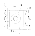
図5は爪保持体2aの正面図(内面側)、図6は図5のA−A断面図、図7は図5のB−B断面図、図8は図5のC−C断面図である。爪保持体2aの中央部15は、外側に膨らむように緩やかに湾曲した形状であり、その内面(耕耘爪1と接触する側)には開口部(上)と底部(下)との間に前記湾曲よりややきつい曲面となった窪み22を形成している。また、中央部15には、前記耕耘爪1のボルト挿通孔8に対応するボルト挿通孔9が形成されており、外面側においてボルト挿通孔9の周囲には、少し隆起した突出部23が形成されている。   5 is a front view (inner side) of the claw holder 2a, FIG. 6 is a cross-sectional view taken along the line AA in FIG. 5, FIG. 7 is a cross-sectional view taken along the line BB in FIG. It is. The central portion 15 of the nail holder 2a is gently curved so as to bulge outward, and the inner surface (the side in contact with the tilling nail 1) is between the opening (upper) and the bottom (lower). A depression 22 having a curved surface slightly tighter than the curve is formed. Further, a bolt insertion hole 9 corresponding to the bolt insertion hole 8 of the tillage claw 1 is formed in the central portion 15, and a slightly raised protrusion 23 is formed around the bolt insertion hole 9 on the outer surface side. Has been.

開口部側と底部側の縁部は、前記窪み22と段差を有する接触部24となっている。接触部24は、内面において左右両側の側部16,17と直角の方向に、この両側部16,17間にわたって形成されている。図8に示したように、接触部24はゆるい曲線状に形成されており、ボルト挿通孔9の中心線から離れるにしたがって傾斜がきつくなるようにしている。   Edges on the opening side and the bottom side are contact portions 24 having a step with the depression 22. The contact portion 24 is formed between the both side portions 16 and 17 in the direction perpendicular to the left and right side portions 16 and 17 on the inner surface. As shown in FIG. 8, the contact portion 24 is formed in a loosely curved shape so that the inclination becomes tighter as the distance from the center line of the bolt insertion hole 9 increases.

なお、爪保持体2aの内面は、中央部15の中心付近において耕耘爪1との間に空隙が生じる部分を有するとともに、その外に耕耘爪1と接触する接触部24(ランド部)を有するものとした構成であればよい。したがって、接触部24は、内面に形成した窪み22の周囲に生じる部分であればよく、内面に意図的に形成した隆起部分として構成する必要はない。また、爪保持体2aの内面を起伏のない平坦な面とし、代わりに耕耘爪1において前記内面に面する部分に窪みや隆起部分を設けることにより、前記内面が耕耘爪1と接触する部分(接触部24)を有するようにした構成とすることもできる。   The inner surface of the nail holder 2a has a portion where a gap is formed between the nail holder 1 and the tilling nail 1 in the vicinity of the center of the central portion 15, and a contact portion 24 (land portion) that contacts the tilling nail 1 outside. Any configuration may be used. Therefore, the contact part 24 should just be a part produced | generated around the hollow 22 formed in the inner surface, and does not need to be comprised as a raised part intentionally formed in the inner surface. Further, the inner surface of the nail holder 2a is a flat surface having no undulations, and instead a portion of the tilling nail 1 that faces the inner surface is provided with a depression or a raised portion so that the inner surface is in contact with the tilling nail 1 ( It can also be configured to have a contact portion 24).

耕耘用作業機の使用時においては、耕耘爪1に作用する外力等により、耕耘爪1の基部1aが傾いたり位置がずれたりし、ボルトの軸力を低下させるような作用が働く。また、ボルトの軸力が低下する原因としては、耕耘爪1に直接的に働く外力の他に、二次的に発生する反動的な力等が関与していることが考えられる。   At the time of using the working machine for tillage, the base 1a of the tilling claw 1 is tilted or displaced due to an external force acting on the tilling claw 1, and the action of reducing the axial force of the bolt works. Moreover, it is conceivable that the axial force of the bolt is reduced, in addition to the external force that acts directly on the tilling claw 1, the reaction force that is secondarily generated is involved.

外力としては、耕耘爪1にかかる耕耘抵抗が主なものである。耕耘抵抗とは、土壌への打ち込み、土壌の反転や粉砕、放てき時に摩擦や衝撃を反力として受ける抵抗力のことである。そして、この力に強い影響を与えるのは、作業機の進行速度、牽引力、耕耘軸の重量、回転速度、耕耘爪1の形状や取付本数等の作業機全体の条件や、その他、耕耘する圃場の条件、すなわち土壌の土質、土性、含水率等である。   As the external force, the tilling resistance applied to the tilling claw 1 is mainly used. Tillage resistance is a resistance force that receives friction and impact as a reaction force when driven into the soil, inverted or crushed, and released. This force has a strong influence on the working machine's speed, traction force, tilling shaft weight, rotation speed, the shape of the tilling claws 1 and the number of attachments, and other conditions of the working machine. These are the soil conditions, soil properties, moisture content, and the like.

二次的に発生する反動的な力としては、耕耘軸に取り付けられた耕耘爪1が、他の耕耘爪1に与えるものが考えられる。耕耘爪1は、1本の耕耘軸に多数本取り付けられており、各耕耘爪1は負荷の変動を受けながらも、一見、等速回転しているように見える。しかし、作業中において、いずれかの耕耘爪1が土壌中に埋没している障害物(石礫、木根等)に衝突した場合には、急激な負の加速が他の耕耘爪1に働くことになる。   As the reactive force that is generated secondarily, what the tilling claw 1 attached to the tilling shaft gives to the other tilling nail 1 can be considered. A number of the tilling claws 1 are attached to one tilling shaft, and each of the tilling claws 1 seems to rotate at a constant speed at a glance while receiving a change in load. However, when one of the tilling claws 1 collides with an obstacle (stone gravel, tree root, etc.) buried in the soil during the work, a sudden negative acceleration works on the other tilling claws 1 become.

このように、耕耘爪1は、他の耕耘爪1の影響によって、二次的に慣性や反動を絶えず繰り返し受けていることになり、これによって耕耘爪1と爪保持体2aとの摩擦力が減少し、ボルトの軸力が低下する可能性がある。   In this way, the tilling claw 1 is constantly subjected to secondary inertia and recoil due to the influence of other tilling claws 1, whereby the frictional force between the tilling claw 1 and the claw holder 2 a is increased. The axial force of the bolt may be reduced.

その他、ボルトの軸力の低下の原因としては、耕耘軸に発生する前後、上下、左右の振動、さらにこれに加えて回転ムラによる回転振動が考えられる。また、回転する耕耘軸を中心とする耕耘爪1の遠心力がボルト軸を中心とするゆるめトルクの働きをすると考えられる。   In addition, as a cause of the decrease in the axial force of the bolt, the vibration before and after, the up and down, the left and right generated on the tilling shaft, and the rotation vibration due to the rotation unevenness can be considered in addition to this. Further, it is considered that the centrifugal force of the tilling claw 1 centering on the rotating tilling shaft acts as a loosening torque centering on the bolt shaft.

ところで、ボルトの軸力は、ボルトの長手方向の弾性変形量によって定まる。したがって、ボルトの長さが短いと、耕耘爪1と爪保持体2aとの接触面に直角に働く力が低下し、摩擦力を維持するためにきわめて不利となる。ボルトの長さは構造上制限があり、一定以上に長くすることはできないが、図5〜8に示した爪保持体2aを利用した耕耘爪取り付け構造では、耕耘爪1又は爪保持体2a(いずれか一方のみ、あるいは双方でもよい)が弾性変形することにより、ボルトの軸力の低下が補償され、耕耘爪1と爪保持体2aとの摩擦力を維持できるようになっている。   Incidentally, the axial force of the bolt is determined by the amount of elastic deformation in the longitudinal direction of the bolt. Therefore, if the length of the bolt is short, the force acting at right angles to the contact surface between the tilling claw 1 and the claw holder 2a is lowered, which is extremely disadvantageous for maintaining the frictional force. The length of the bolt is structurally limited and cannot be longer than a certain length. However, in the cultivation claw attachment structure using the claw holder 2a shown in FIGS. 5 to 8, the cultivation claw 1 or the claw holder 2a ( The elastic deformation of either one or both) compensates for a decrease in the axial force of the bolt, so that the frictional force between the tilling claw 1 and the claw holder 2a can be maintained.

さらには、外力によって変位する耕耘爪1と爪保持体2aとの接触により、それぞれの表面の塗膜が破壊されると、両者の塗膜に覆われていた部分が露出し、金属面同士の接触が生じるが、金属面同士の接触が進行すると、塗膜同士の接触に比べて摩擦係数が増大し、より大きな摩擦力が発生することになる。   Furthermore, when the coating film on each surface is destroyed by the contact between the tillage nail 1 and the nail holder 2a which are displaced by an external force, the portions covered with both coating films are exposed, and the metal surfaces Although contact occurs, when the contact between the metal surfaces proceeds, the friction coefficient increases as compared with the contact between the coating films, and a larger frictional force is generated.

つまり、図5〜8に示した爪保持体2aを利用した耕耘爪取り付け構造においては、ボルトの弾性変形量と耕耘爪1、爪保持体2aの弾性変形量とを合わせた締結体の総弾性変形量を大きくし、外力によって耕耘爪1が変位する量を利用する構造にして、耕耘爪1と爪保持体2aとの摩擦力の減少を補うとともに、早期に金属面同士の接触を進行させることにより摩擦力が増大するようになっている。そのため、初期ゆるみ(非回転ゆるみ)段階における軸力低下が外力を利用して自動的に補償されるのであり、また、外力を利用するということは、耕耘爪1に加わる衝撃を緩衝する働きもある。   That is, in the tilling claw attachment structure using the claw holding body 2a shown in FIGS. 5 to 8, the total elasticity of the fastening body that combines the elastic deformation amount of the bolt and the elastic deformation amounts of the tilling claw 1 and the claw holding body 2a. The amount of deformation is increased and the amount of displacement of the tilling claw 1 by an external force is used to compensate for the reduction in frictional force between the tilling claw 1 and the claw holder 2a, and the contact between the metal surfaces is advanced at an early stage. As a result, the frictional force increases. Therefore, the decrease in axial force in the initial loosening (non-rotational loosening) stage is automatically compensated by using external force, and the use of external force also serves to buffer the impact applied to the tilling nail 1. is there.

なお、爪保持体2aは湾曲した形状であるため、より大きな弾性が得られるようになっている。また、接触部24は、開口部付近と底部側付近に形成されており、回転の中心となるボルト挿通孔9の中心から遠い位置にあるため、耕耘爪1をゆるめようとするトルクに対抗し得る大きな摩擦トルクが得られるようになっている。   In addition, since the nail | claw holding | maintenance body 2a is a curved shape, greater elasticity is obtained. Further, the contact portion 24 is formed in the vicinity of the opening and near the bottom, and is located far from the center of the bolt insertion hole 9 that is the center of rotation, so that it resists torque that tends to loosen the tillage claw 1. A large friction torque can be obtained.

以上、この発明は、上述の実施形態の構成に限定されるものではなく、素材、形状、寸法等を適宜変更して実施することができる。   As mentioned above, this invention is not limited to the structure of the above-mentioned embodiment, It can implement by changing a raw material, a shape, a dimension, etc. suitably.

この発明の実施形態の耕耘爪取り付け構造の要部の断面図である。It is sectional drawing of the principal part of the tilling nail attachment structure of embodiment of this invention. この発明の実施形態の耕耘爪取り付け構造の説明図である。It is explanatory drawing of the cultivation nail attachment structure of embodiment of this invention. この発明の他の実施形態の耕耘爪取り付け構造におけるホルダの一部の説明図である。It is explanatory drawing of a part of holder in the tilling nail attachment structure of other embodiment of this invention. この発明の他の実施形態の耕耘爪取り付け構造におけるホルダの説明図である。It is explanatory drawing of the holder in the tilling nail attachment structure of other embodiment of this invention. この発明の実施形態の耕耘爪取り付け構造の爪保持体の正面図(内面側)である。It is a front view (inner surface side) of the nail | claw holding | maintenance body of the cultivation nail attachment structure of embodiment of this invention. 図5のA−A断面図である。It is AA sectional drawing of FIG. 図5のB−B断面図である。It is BB sectional drawing of FIG. 図5のC−C断面図である。It is CC sectional drawing of FIG. 従来の耕耘爪取り付け構造(ホルダ方式)の斜視図である。It is a perspective view of the conventional tillage nail attachment structure (holder system). 従来の耕耘爪取り付け構造(ホルダ方式)の要部の断面図である。It is sectional drawing of the principal part of the conventional tillage nail attachment structure (holder system). 従来の耕耘爪取り付け構造(フランジ方式)の説明図である。It is explanatory drawing of the conventional tilling nail attachment structure (flange system). 従来の耕耘爪取り付け構造(フランジ方式)の要部の断面図である。It is sectional drawing of the principal part of the conventional tillage nail attachment structure (flange system).

符号の説明Explanation of symbols

1 耕耘爪
1a 基部
2 ホルダ
3 穴
4,5 ブラケット部
6 耕耘爪の基部の厚みの中心線
7 ブラケット部の厚みの中心線
8,9,10 ボルト挿通孔
11 ボルト
12 ナット
13 耕耘軸
14 板
DESCRIPTION OF SYMBOLS 1 Tillage claw 1a Base 2 Holder 3 Hole 4,5 Bracket part 6 Centerline of thickness of base of tillage claw 7 Centerline of thickness of bracket part 8, 9, 10 Bolt insertion hole 11 Bolt 12 Nut 13 Cultivation shaft 14 Plate

Claims (4)

耕耘爪(1)の基部(1a)をホルダ(2)の穴(3)に挿入して耕耘爪(1)を保持するようにした耕耘爪取り付け構造であって、ホルダ(2)は左右両側にそれぞれ左右方向に延びるブラケット部(4)(5)を有しており、両側のブラケット部(4)(5)間に耕耘爪(1)の基部(1a)が位置するようにしていることを特徴とする耕耘爪取り付け構造。   A tilling claw mounting structure in which the base (1a) of the tilling claw (1) is inserted into the hole (3) of the holder (2) to hold the tilling claw (1). Each has a bracket portion (4) (5) extending in the left-right direction, and the base portion (1a) of the tilling claw (1) is positioned between the bracket portions (4) (5) on both sides. Tillage claw attachment structure characterized by 耕耘爪(1)の基部(1a)の厚みの中心線(6)と、両側のブラケット部(4)(5)の厚みの中心線(7)が、略一直線状となるようにした請求項1記載の耕耘爪取り付け構造。   The center line (6) of the thickness of the base part (1a) of the tillage claw (1) and the center lines (7) of the thicknesses of the bracket parts (4) and (5) on both sides are substantially straight. The tilling nail attachment structure according to 1. 耕耘爪(1)の基部(1a)とホルダ(2)にそれぞれボルト挿通孔(8)(9)(10)を設け、1組のボルト(11)とナット(12)で締め付け固定するようにした請求項1又は2記載の耕耘爪取り付け構造。   Bolt insertion holes (8), (9), and (10) are provided in the base (1a) of the tillage claw (1) and the holder (2), respectively, and are fastened and fixed with a set of bolts (11) and nuts (12). The tillage nail attachment structure according to claim 1 or 2. ブラケット部(4)(5)が、耕耘軸(13)の周囲に設けられた板(14)の一部として構成されている請求項1、2又は3記載の耕耘爪取り付け構造。
The tilling nail attachment structure according to claim 1, 2, or 3, wherein the bracket portion (4) (5) is configured as a part of a plate (14) provided around the tilling shaft (13).
JP2006336698A 2006-12-14 2006-12-14 Tillage tine-attaching structure Pending JP2008148564A (en)

Priority Applications (1)

Application Number Priority Date Filing Date Title
JP2006336698A JP2008148564A (en) 2006-12-14 2006-12-14 Tillage tine-attaching structure

Applications Claiming Priority (1)

Application Number Priority Date Filing Date Title
JP2006336698A JP2008148564A (en) 2006-12-14 2006-12-14 Tillage tine-attaching structure

Publications (1)

Publication Number Publication Date
JP2008148564A true JP2008148564A (en) 2008-07-03

Family

ID=39651483

Family Applications (1)

Application Number Title Priority Date Filing Date
JP2006336698A Pending JP2008148564A (en) 2006-12-14 2006-12-14 Tillage tine-attaching structure

Country Status (1)

Country Link
JP (1) JP2008148564A (en)

Citations (4)

* Cited by examiner, † Cited by third party
Publication number Priority date Publication date Assignee Title
JPS5223903U (en) * 1975-08-09 1977-02-19
JPS59187906U (en) * 1983-06-01 1984-12-13 太陽鍛工株式会社 Tilling claw support means
JPH0160606U (en) * 1987-10-12 1989-04-18
JPH035305U (en) * 1989-05-31 1991-01-18

Patent Citations (4)

* Cited by examiner, † Cited by third party
Publication number Priority date Publication date Assignee Title
JPS5223903U (en) * 1975-08-09 1977-02-19
JPS59187906U (en) * 1983-06-01 1984-12-13 太陽鍛工株式会社 Tilling claw support means
JPH0160606U (en) * 1987-10-12 1989-04-18
JPH035305U (en) * 1989-05-31 1991-01-18

Similar Documents

Publication Publication Date Title
SE533207C2 (en) Wear part for a bucket for a loading or excavator, mounting unit there for as well as wear part system, bucket and loading or excavator
JP3098188B2 (en) Tillage claw
AU2006319766B2 (en) Fastening assembly
JP2008148564A (en) Tillage tine-attaching structure
JPH0525014U (en) Fastening parts such as bolts and rivets
JP5273413B2 (en) Tillage claw mounting structure
JP4505844B2 (en) Tillage claw mounting structure
JPH0893178A (en) Dry execution mounting bearing construction of walling
JPH051210Y2 (en)
JP3201474U (en) Steel frame corner protection jig
KR101551130B1 (en) Connection parts for Composite Piles
JP5737542B1 (en) Tillage claw mounting structure
JPH0737442Y2 (en) Supporting means for tillage nails
JPH05196176A (en) Screw wahser for fixing piping of construction machine
JPH0748001Y2 (en) Plow support structure
JP2535561Y2 (en) Tiller support
JP3249414U (en) Electric screwdriver protective cover
JPH0737443Y2 (en) Holding means for tilling nails
JP5936308B2 (en) Apron material
EP1164225A1 (en) Earthquake-proofing reinforcing metal fitting
JPH08807Y2 (en) Supporting means for tillage nails
JP2012187029A (en) Rotary operating machine
JP6823835B2 (en) Supporting device for hoisting machine in elevator
JP2532259Y2 (en) Tilling nail support means
JP2002038522A (en) Center frame turning support device

Legal Events

Date Code Title Description
A621 Written request for application examination

Effective date: 20081003

Free format text: JAPANESE INTERMEDIATE CODE: A621

A977 Report on retrieval

Free format text: JAPANESE INTERMEDIATE CODE: A971007

Effective date: 20091026

A131 Notification of reasons for refusal

Free format text: JAPANESE INTERMEDIATE CODE: A131

Effective date: 20091028

A02 Decision of refusal

Effective date: 20100325

Free format text: JAPANESE INTERMEDIATE CODE: A02