JP2008138564A - Engine exhaust system provided with dpf device - Google Patents
Engine exhaust system provided with dpf device Download PDFInfo
- Publication number
- JP2008138564A JP2008138564A JP2006324638A JP2006324638A JP2008138564A JP 2008138564 A JP2008138564 A JP 2008138564A JP 2006324638 A JP2006324638 A JP 2006324638A JP 2006324638 A JP2006324638 A JP 2006324638A JP 2008138564 A JP2008138564 A JP 2008138564A
- Authority
- JP
- Japan
- Prior art keywords
- dpf
- bypass valve
- engine
- exhaust gas
- black smoke
- Prior art date
- Legal status (The legal status is an assumption and is not a legal conclusion. Google has not performed a legal analysis and makes no representation as to the accuracy of the status listed.)
- Granted
Links
- 239000004071 soot Substances 0.000 claims abstract description 78
- 239000000779 smoke Substances 0.000 claims abstract description 48
- 238000011144 upstream manufacturing Methods 0.000 claims abstract description 14
- 239000007787 solid Substances 0.000 claims abstract description 12
- 239000000446 fuel Substances 0.000 abstract description 17
- 230000001603 reducing effect Effects 0.000 abstract description 5
- 230000001276 controlling effect Effects 0.000 abstract 1
- 230000001105 regulatory effect Effects 0.000 abstract 1
- 101100224419 Caenorhabditis elegans dpf-2 gene Proteins 0.000 description 54
- 238000001514 detection method Methods 0.000 description 21
- 238000010586 diagram Methods 0.000 description 18
- 238000004364 calculation method Methods 0.000 description 15
- 230000003197 catalytic effect Effects 0.000 description 15
- 230000001965 increasing effect Effects 0.000 description 14
- 230000003247 decreasing effect Effects 0.000 description 12
- 230000003647 oxidation Effects 0.000 description 8
- 238000007254 oxidation reaction Methods 0.000 description 8
- 230000004044 response Effects 0.000 description 7
- 239000003054 catalyst Substances 0.000 description 6
- 238000002347 injection Methods 0.000 description 6
- 239000007924 injection Substances 0.000 description 6
- 238000000034 method Methods 0.000 description 6
- 238000002844 melting Methods 0.000 description 5
- 230000008018 melting Effects 0.000 description 5
- XSQUKJJJFZCRTK-UHFFFAOYSA-N Urea Chemical compound NC(N)=O XSQUKJJJFZCRTK-UHFFFAOYSA-N 0.000 description 4
- 239000004202 carbamide Substances 0.000 description 4
- 238000002485 combustion reaction Methods 0.000 description 4
- 238000013021 overheating Methods 0.000 description 4
- 230000004043 responsiveness Effects 0.000 description 4
- 101000708874 Homo sapiens Zinc finger protein ubi-d4 Proteins 0.000 description 3
- 102100032701 Zinc finger protein ubi-d4 Human genes 0.000 description 3
- 238000004088 simulation Methods 0.000 description 3
- 238000002474 experimental method Methods 0.000 description 2
- 238000000746 purification Methods 0.000 description 2
- 230000008929 regeneration Effects 0.000 description 2
- 238000011069 regeneration method Methods 0.000 description 2
- OKTJSMMVPCPJKN-UHFFFAOYSA-N Carbon Chemical compound [C] OKTJSMMVPCPJKN-UHFFFAOYSA-N 0.000 description 1
- 230000006866 deterioration Effects 0.000 description 1
- 230000002708 enhancing effect Effects 0.000 description 1
- 229910002804 graphite Inorganic materials 0.000 description 1
- 239000010439 graphite Substances 0.000 description 1
- 239000000463 material Substances 0.000 description 1
- 230000001737 promoting effect Effects 0.000 description 1
- 230000001172 regenerating effect Effects 0.000 description 1
- 230000009897 systematic effect Effects 0.000 description 1
- 230000037303 wrinkles Effects 0.000 description 1
Images

Landscapes
- Exhaust Gas After Treatment (AREA)
- Processes For Solid Components From Exhaust (AREA)
Abstract
Description
本発明は、エンジンからの排気通路に、排ガス中の煤等の固形排出物を捕獲する黒煙除去装置即ちDPF(ディーゼルパティキュレートフィルタ)をそなえたエンジンの排気装置に関する。 The present invention relates to an exhaust system for an engine provided with a black smoke removing device, that is, a DPF (diesel particulate filter), for capturing solid emissions such as soot in exhaust gas in an exhaust passage from the engine.
ディーゼルエンジンの排気装置においては、エンジンからの排気通路に、還元触媒コンバータ、酸化触媒コンバータ、これらの上流側に排ガス中の煤等の固形排出物を捕獲する黒煙除去装置即ちDPF(ディーゼルパティキュレートフィルタ)をそなえた排ガス浄化システムが多く用いられている。
図10は、かかるディーゼルエンジン用排気装置における排ガス浄化システムの従来の一例を示す。図10において、エンジン1には図示しない過給機からの給気が給気通路7を通して供給され、該給気と燃料とによる燃焼後の排ガスは排気通路を通してDPF(ディーゼルパティキュレートフィルタ)2に入り、該DPF2で排ガス中の煤等の固形排出物が捕獲される。
前記DPF2にて煤を除去された排ガスは、尿素噴射システム5からの還元作用促進用尿素が混入され還元触媒コンバータ3でNOxが除去された後、酸化触媒コンバータ4でHC,CO等が除去されてから、大気中に排出される。
In an exhaust system of a diesel engine, a reduction catalytic converter and an oxidation catalytic converter are disposed in an exhaust passage from the engine, and a black smoke removing apparatus or DPF (diesel particulates) that captures solid emissions such as soot in exhaust gas upstream of these. An exhaust gas purification system having a filter is often used.
FIG. 10 shows a conventional example of an exhaust gas purification system in such an exhaust device for a diesel engine. In FIG. 10, the
The exhaust gas from which the soot has been removed by the
図10に示されるような、排気通路中にDPF、還元触媒コンバータ、及び酸化触媒コンバータを設置したエンジンの排気装置の一つとして特許文献1(特開2002−3492411号公報)の技術が提供されている。
また、特許文献2(特開2003−286834号公報)の技術においては、排気通路中に触媒付きのDPF(ディーゼルパティキュレートフィルタ)を設けるとともに、該DPFをバイパスするバイパス排気通路及びエンジン運転条件により該バイパス排気通路を開閉するDPFバイパス弁を設置している。
As shown in FIG. 10, the technology of Patent Document 1 (Japanese Patent Laid-Open No. 2002-349241) is provided as one of engine exhaust devices in which a DPF, a reduction catalytic converter, and an oxidation catalytic converter are installed in an exhaust passage. ing.
Further, in the technique of Patent Document 2 (Japanese Patent Laid-Open No. 2003-286834), a DPF (diesel particulate filter) with a catalyst is provided in the exhaust passage, and the bypass exhaust passage bypassing the DPF and the engine operating conditions are used. A DPF bypass valve that opens and closes the bypass exhaust passage is provided.
図10に示されるような、排気通路6中にDPF2、還元触媒コンバータ3、及び酸化触媒コンバータ4を設置したエンジンの排気装置においては、排気通路6中に流路抵抗の大きいDPF2、還元触媒コンバータ3、及び酸化触媒コンバータ4を直列に配置しているため、排気系の圧力損失が大きく、エンジンの燃費(燃料消費率)悪化の要因の一つとなっている。
特に、前記DPFにおいては、煤等の固形排出物(以下煤と総称する)が堆積して行くと、前記圧力損失の増大及び燃費(燃料消費率)悪化が著しくなるため、DPFに触媒を担持させる方法や、排ガス中にアフター燃料噴射を行なう方法等によって排気温度を上昇させ煤を燃焼させることにより、DPFを再生させる手段が一般的に採用されている。
しかしながら、このような排気温度を上昇させる手段では、煤の燃焼量が過大になった場合や燃焼速度が過大になった場合、エアフィルタや過給機の能力低減を招きエンジン空気量が減少して排気温度が過度に上昇し、DPFの溶損が発生することがある。
In the exhaust system for an engine in which the
In particular, in the DPF, when solid discharge such as soot (hereinafter collectively referred to as soot) accumulates, the pressure loss increases and the fuel consumption (fuel consumption rate) deteriorates significantly. Generally, means for regenerating the DPF by raising the exhaust gas temperature and burning the soot by a method of causing the exhaust gas to be injected into the exhaust gas, or a method of injecting after-fuel into the exhaust gas is employed.
However, with such means for increasing the exhaust temperature, when the combustion amount of soot is excessive or the combustion speed is excessive, the capacity of the air filter and the supercharger is reduced, and the engine air amount is reduced. As a result, the exhaust temperature may rise excessively, resulting in melting of the DPF.
前記特許文献2(特開2003−286834号公報)の技術では、排気通路中に触媒付きのDPFを設けるとともに、該DPFをバイパスするバイパス排気通路及び該バイパス排気通路を開閉するDPFバイパス弁を設置して、エンジン負荷等のエンジン運転条件により該バイパス排気通路を開閉しており、DPFバイパス弁の開度を調整することにより、DPFを流れる排ガス流量を調整できるので、前記のような排気温度の過度の上昇はある程度回避できる。 In the technique disclosed in Patent Document 2 (Japanese Patent Laid-Open No. 2003-286834), a DPF with a catalyst is provided in an exhaust passage, and a bypass exhaust passage that bypasses the DPF and a DPF bypass valve that opens and closes the bypass exhaust passage are provided. Then, the bypass exhaust passage is opened and closed according to engine operating conditions such as engine load, and the exhaust gas flow rate flowing through the DPF can be adjusted by adjusting the opening of the DPF bypass valve. Excessive rise can be avoided to some extent.
しかしながら、前記特許文献2の技術にあっては、エンジン負荷及び排気温度の検出値に基づき、触媒付きのDPF下流の排気温度が所定値以下のときは触媒付きのDPFへの排ガス流量を減少させ、エンジン負荷が所定値以下のときは前記DPFへの排ガス流量を減少させた後、エンジン負荷が所定値を上回るとDPFへの排ガス流量を増加させる制御を行なっているにとどまり、エンジン回転数、エンジン負荷等のエンジン運転条件、DPF出入口の排気温度、DPF自体の温度等の広範囲の制御因子によってDPFを通る排ガス量及びDPFの作動を高精度に制御する手段は開示されていない。
等の解決すべき課題を抱えている。
However, in the technique of
Have problems to be solved.
本発明はかかる従来技術の課題に鑑み、エンジン回転数、エンジン負荷等のエンジン運転条件とDPFにおける煤除去機能及び圧力損失との最適関係を精緻に設定するとともに、DPF出入口の排気温度、DPF自体の温度等の広範囲の制御因子によってDPFを通る排ガス量及びDPFの作動を高精度に制御可能として、排気抵抗を低減してエンジンの燃費を低減すると共に、DPF装置の耐久性を向上したDPF装置をそなえたエンジンの排気装置を提供することを目的とする。 In view of the problems of the prior art, the present invention precisely sets the optimal relationship between engine operating conditions such as engine speed, engine load, etc., soot removal function and pressure loss in the DPF, as well as the exhaust temperature of the DPF inlet / outlet, the DPF itself DPF device that can control the exhaust gas amount passing through the DPF and the operation of the DPF with high accuracy by a wide range of control factors such as the temperature of the engine, reduce the exhaust resistance, reduce the fuel consumption of the engine, and improve the durability of the DPF device It is an object of the present invention to provide an exhaust system for an engine equipped with the above.
本発明はかかる目的を達成するもので、エンジンからの排気通路に、排ガス中の煤等の固形排出物を捕獲する黒煙除去装置(DPF)をそなえたエンジンにおいて、前記排気通路の黒煙除去装置の上流部位から分岐されて該黒煙除去装置の下流部位に接続されるDPFバイパス通路と、該DPFバイパス通路を開閉するとともに通路面積を調整するDPFバイパス弁と、エンジン回転数及びエンジン負荷に対する前記DPFバイパス弁の適正開度が設定されたDPFバイパス弁開度マップをそなえて前記エンジン回転数及びエンジン負荷の検出値に基づき前記DPFバイパス弁開度マップからDPFバイパス弁の適正開度を算出するコントローラとをそなえたことを特徴とする。
かかる発明において、好ましくは、前記DPFバイパス弁開度マップには、エンジン回転数及びエンジン負荷とエンジンの煤排出量との関係、並びに該煤排出量による前記DPFバイパス弁の開放条件が設定されており、前記コントローラは、前記エンジン回転数及びエンジン負荷において前記煤排出量が前記DPFバイパス弁の開放条件となる煤排出量以下になったとき前記DPFバイパス弁を開くように構成される。
The present invention achieves such an object. In an engine provided with a black smoke removal device (DPF) for capturing solid emissions such as soot in exhaust gas in an exhaust passage from the engine, the black smoke removal in the exhaust passage is achieved. A DPF bypass passage branched from the upstream portion of the apparatus and connected to the downstream portion of the black smoke removing device, a DPF bypass valve for opening and closing the DPF bypass passage and adjusting the passage area, and for engine speed and engine load An appropriate opening degree of the DPF bypass valve is calculated from the DPF bypass valve opening degree map based on the detected value of the engine speed and the engine load by providing a DPF bypass valve opening degree map in which the appropriate opening degree of the DPF bypass valve is set. It is characterized by having a controller.
In this invention, preferably, the DPF bypass valve opening degree map includes a relationship between the engine speed and the engine load and the soot discharge amount of the engine, and an opening condition of the DPF bypass valve according to the soot discharge amount. The controller is configured to open the DPF bypass valve when the soot discharge amount becomes equal to or less than the soot discharge amount that is a condition for opening the DPF bypass valve at the engine speed and the engine load.
かかる発明によれば、コントローラにおいて、エンジン回転数及びエンジン負荷とエンジンの煤排出量との関係、並びに該煤排出量によるDPFバイパス弁のDPFバイパス通路の開閉条件を、シミュレーション計算あるいは実験によって最適値に予め設定したDPFバイパス弁開度マップを用いて、エンジン回転数及びエンジン負荷の検出値に基づき前記DPFバイパス弁開度マップからDPFバイパス弁の適正開度を算出して、かかる適正開度によってDPFバイパス弁を開閉制御するので、前記DPFバイパス弁開度マップに精緻に設定したエンジン回転数及びエンジン負荷等のエンジン運転条件とDPFにおける煤除去機能及び圧力損失との最適関係によって、DPFバイパス弁の開閉制御を行なうことにより、DPFの煤除去機能を高く保持し且つDPF圧力損失を抑制した運転を行なうことが可能となる。
これにより、DPFの排気抵抗を低減してエンジンの燃費を低減すると共に、DPF装置の耐久性を向上できる。
According to this invention, in the controller, the relationship between the engine speed and the engine load and the soot discharge amount of the engine, and the open / close conditions of the DPF bypass passage of the DPF bypass valve due to the soot discharge amount are optimized by simulation calculation or experiment. Using the DPF bypass valve opening map set in advance, the appropriate opening of the DPF bypass valve is calculated from the DPF bypass valve opening map based on the detected value of the engine speed and the engine load. Since the DPF bypass valve is controlled to open and close, the DPF bypass valve is determined according to the optimum relationship between engine operating conditions such as the engine speed and engine load, which are precisely set in the DPF bypass valve opening map, and soot removal function and pressure loss in the DPF. DPF wrinkle removal function by opening / closing control Held high and it is possible to perform operation that suppresses the DPF pressure loss.
Thereby, the exhaust resistance of the DPF can be reduced to reduce the fuel consumption of the engine, and the durability of the DPF device can be improved.
また本発明は、前記エンジンにおいて、前記排気通路の黒煙除去装置の上流部位から分岐されて該黒煙除去装置の下流部位に接続されるDPFバイパス通路と、該DPFバイパス通路を開閉するとともに通路面積を調整するDPFバイパス弁と、前記黒煙除去装置における差圧の検出値に基づき該黒煙除去装置の圧損(圧力損失)上昇率を算出する圧損上昇率算出手段をそなえて前記圧損上昇率が予め設定された基準圧損上昇率以下のとき前記DPFバイパス弁を開放せしめるコントローラとをそなえたことを特徴とする。 According to the present invention, in the engine, a DPF bypass passage branched from an upstream portion of the black smoke removal device in the exhaust passage and connected to a downstream portion of the black smoke removal device, and a passage for opening and closing the DPF bypass passage The pressure loss increase rate includes a DPF bypass valve that adjusts the area, and a pressure loss increase rate calculating means that calculates a pressure loss (pressure loss) increase rate of the black smoke removal device based on a detected value of the differential pressure in the black smoke removal device. And a controller for opening the DPF bypass valve when the pressure is below a preset reference pressure loss increase rate.
かかる発明によれば、DPFバイパス弁の開閉制御にDPFにおける圧損(圧力損失)上昇率を取り入れ、この圧損上昇率が予め設定された基準圧損上昇率つまり許容圧損上昇率以下のときはエンジンの煤発生量が少ないと判断してDPFバイパス弁を開放せしめてDPFへの排ガス流量を減少させ、前記圧損上昇率が前記基準圧損上昇率つまり許容圧損上昇率を超えるときはエンジンの煤発生量が多いと判断してDPFバイパス弁を閉鎖あるいは開度を減少せしめてDPFへの排ガス流量を増加させ、DPFにおける煤除去機能を上昇させることが可能となり、常時DPFの煤除去機能を高く保持し且つDPF圧力損失を許容値以下に抑制した運転を行なうことが可能となる。
殊に、DPFバイパス弁の開閉制御に、DPFにおける圧損上昇率を取り入れたことによって、DPF圧損の急変化に迅速に対応してDPFの排ガス流量を変化させることが可能となって、DPFの排ガス流量制御の応答性が向上する。
According to this invention, the pressure loss (pressure loss) increase rate in the DPF is taken into the opening / closing control of the DPF bypass valve, and when the pressure loss increase rate is less than the preset reference pressure loss increase rate, that is, the allowable pressure loss increase rate, the engine It is judged that the generation amount is small, and the DPF bypass valve is opened to reduce the exhaust gas flow rate to the DPF. When the pressure loss increase rate exceeds the reference pressure loss increase rate, that is, the allowable pressure loss increase rate, the engine soot generation amount is large. It is possible to increase the exhaust gas flow rate to the DPF by closing the DPF bypass valve or decreasing the opening degree and increasing the soot removal function in the DPF, and always keep the soot removal function of the DPF high and the DPF It is possible to perform an operation in which the pressure loss is suppressed to an allowable value or less.
In particular, by incorporating the rate of increase in pressure loss in the DPF into the opening / closing control of the DPF bypass valve, it becomes possible to change the exhaust gas flow rate of the DPF in response to a sudden change in the DPF pressure loss. The response of flow control is improved.
また本発明は、前記エンジンにおいて、前記排気通路の黒煙除去装置の上流部位から分岐されて該黒煙除去装置の下流部位に接続されるDPFバイパス通路と、該DPFバイパス通路を開閉するとともに通路面積を調整するDPFバイパス弁と、前記黒煙除去装置における差圧の検出値に基づく該黒煙除去装置の圧損上昇率の算出値が予め設定された基準圧損上昇率以下で、且つ前記黒煙除去装置における排ガスの出入口温度差の検出値が予め設定された基準排ガス出入口温度差以下で、且つ前記黒煙除去装置における内部温度の検出値が予め設定された基準DPF内部温度以下のとき、前記DPFバイパス弁を開放せしめるコントローラとをそなえたことを特徴とする。 According to the present invention, in the engine, a DPF bypass passage branched from an upstream portion of the black smoke removal device in the exhaust passage and connected to a downstream portion of the black smoke removal device, and a passage for opening and closing the DPF bypass passage A calculated value of the pressure loss increase rate of the black smoke removal device based on the detected value of the differential pressure in the DPF bypass valve for adjusting the area and the black smoke removal device is equal to or less than a preset reference pressure loss increase rate, and the black smoke When the detected value of the exhaust gas inlet / outlet temperature difference in the removal device is less than or equal to a preset reference exhaust gas inlet / outlet temperature difference, and the detected value of the internal temperature in the black smoke removal device is less than or equal to the preset reference DPF internal temperature, And a controller for opening the DPF bypass valve.
かかる発明によれば、前記のようにDPFバイパス弁の開閉制御に、DPFにおける圧損上昇率を取り入れたのに加えて、DPFにおける排ガスの出入口温度差及びDPFの内部温度を取り入れ、DPFにおける排ガス出入口温度差が予め設定された基準排ガス出入口温度差、つまり許容排ガス出入口温度差以下のときはDPFでの煤除去作用が小さいと判断してDPFバイパス弁を開放せしめてDPFの排ガス流量を減少させ、前記排ガス出入口温度差が許容排ガス出入口温度差を超えたときにはDPFでの煤除去作用が活発と判断してDPFバイパス弁を閉鎖あるいは開度を減少せしめてDPFへの排ガス流量を増加させ、
DPFの内部温度が予め設定された基準DPF内部温度つまり許容DPF内部温度以下のときはDPFでの煤除去作用が小さいと判断してDPFバイパス弁を開放せしめてDPFの排ガス流量を減少させ、前記DPFの内部温度が許容DPF内部温度を超えたときにはDPFでの煤除去作用が活発と判断して、DPFバイパス弁を閉鎖あるいは開度を減少せしめてDPFへの排ガス流量を増加させることが可能となる。
According to this invention, in addition to incorporating the pressure loss increase rate in the DPF into the opening / closing control of the DPF bypass valve as described above, the exhaust gas inlet / outlet temperature difference in the DPF and the internal temperature of the DPF are incorporated, and the exhaust gas inlet / outlet in the DPF When the temperature difference is less than the preset reference exhaust gas inlet / outlet temperature difference, that is, the allowable exhaust gas inlet / outlet temperature difference, it is judged that the soot removal action in the DPF is small and the DPF bypass valve is opened to reduce the exhaust gas flow rate of the DPF, When the exhaust gas inlet / outlet temperature difference exceeds the allowable exhaust gas inlet / outlet temperature difference, it is determined that the soot removing action in the DPF is active, and the DPF bypass valve is closed or the opening degree is decreased to increase the exhaust gas flow rate to the DPF,
When the internal temperature of the DPF is equal to or lower than a preset reference DPF internal temperature, that is, the allowable DPF internal temperature, it is determined that the soot removing action in the DPF is small, and the DPF bypass valve is opened to reduce the exhaust gas flow rate of the DPF, When the internal temperature of the DPF exceeds the allowable internal temperature of the DPF, it is determined that the soot removal action of the DPF is active, and the exhaust gas flow rate to the DPF can be increased by closing the DPF bypass valve or decreasing the opening degree. Become.
従って、かかる発明によれば、DPFバイパス弁の開閉制御に、DPFにおける圧損上昇率に加えて、DPFにおける排ガスの出入口温度差及びDPFの内部温度を取り入れたことにより、DPF圧損の急変化に迅速に対応してDPFの排ガス流量を変化させることが可能となってDPFの排ガス流量制御の応答性が向上するとともに、排ガスの出入口温度差及びDPFの内部温度によってDPFの煤除去作用状態を検知してDPFにおける排ガス流量を行なうことにより、DPFの排ガス流量制御の精度が向上する。 Therefore, according to this invention, in addition to the rate of increase in pressure loss in the DPF, in addition to the rate of increase in pressure loss in the DPF, the exhaust gas inlet / outlet temperature difference and the internal temperature of the DPF are incorporated into the opening / closing control of the DPF bypass valve. It is possible to change the exhaust gas flow rate of the DPF in response to the above, improving the responsiveness of the exhaust gas flow rate control of the DPF, and detecting the state of the DPF soot removal action based on the temperature difference of the exhaust gas inlet and outlet and the internal temperature of the DPF. By performing the exhaust gas flow rate in the DPF, the accuracy of exhaust gas flow rate control of the DPF is improved.
また本発明は、前記エンジンにおいて、前記排気通路の黒煙除去装置の上流部位から分岐されて該黒煙除去装置の下流部位に接続されるDPFバイパス通路と、該DPFバイパス通路を開閉するとともに通路面積を調整するDPFバイパス弁と、前記黒煙除去装置における差圧の検出値が予め設定された基準差圧を超えたとき、DPFバイパス弁を閉じて前記DPFの排ガス流量を前記差圧検出値に対応する基準排ガス流量に増加させるコントローラとをそなえたことを特徴とする。 According to the present invention, in the engine, a DPF bypass passage branched from an upstream portion of the black smoke removal device in the exhaust passage and connected to a downstream portion of the black smoke removal device, and a passage for opening and closing the DPF bypass passage When the detected value of the differential pressure in the DPF bypass valve for adjusting the area and the black smoke removing device exceeds a preset reference differential pressure, the DPF bypass valve is closed and the exhaust gas flow rate of the DPF is set to the detected differential pressure value. And a controller for increasing the reference exhaust gas flow rate corresponding to the above.
かかる発明によれば、DPF再生時等において、DPFの差圧が基準値(基準差圧)を超えた場合、DPFバイパス弁を閉じてDPFへの排ガス流量を増加して、DPFから熱を取り去ることにより、DPFの過熱による溶損の発生を防止できる。 According to this invention, when the differential pressure of the DPF exceeds a reference value (reference differential pressure) during regeneration of the DPF, etc., the DPF bypass valve is closed to increase the exhaust gas flow rate to the DPF, thereby removing heat from the DPF. Thus, it is possible to prevent the occurrence of melting damage due to overheating of the DPF.
また本発明は、前記エンジンにおいて、前記排気通路の黒煙除去装置の上流部位から分岐されて該黒煙除去装置の下流部位に接続されるDPFバイパス通路と、該DPFバイパス通路を開閉するとともに通路面積を調整するDPFバイパス弁と、前記黒煙除去装置における内部温度の検出値に基づき該黒煙除去装置の温度上昇率を算出する温度上昇率算出手段をそなえて、前記温度上昇率が予め設定された基準温度上昇率を超えるとき前記DPFバイパス弁を閉じるコントローラとをそなえたことを特徴とする。 According to the present invention, in the engine, a DPF bypass passage branched from an upstream portion of the black smoke removal device in the exhaust passage and connected to a downstream portion of the black smoke removal device, and a passage for opening and closing the DPF bypass passage The temperature increase rate is preset by providing a DPF bypass valve for adjusting the area and a temperature increase rate calculating means for calculating the temperature increase rate of the black smoke removal device based on a detected value of the internal temperature in the black smoke removal device. And a controller for closing the DPF bypass valve when the reference temperature increase rate is exceeded.
かかる発明によれば、DPFに基準温度上昇率を超える急激な温度上昇があった場合には、DPFバイパス弁を閉じてDPFへの排ガス流量を増加して、DPFから熱を取り去ることによりDPFの温度上昇を抑制することにより、DPFの過熱による溶損の発生を防止できる。 According to this invention, when the DPF has a rapid temperature rise exceeding the reference temperature rise rate, the DPF bypass valve is closed, the exhaust gas flow rate to the DPF is increased, and the heat of the DPF is removed by removing the heat from the DPF. By suppressing the temperature rise, it is possible to prevent the occurrence of melting damage due to overheating of the DPF.
本発明によれば、エンジン回転数及びエンジン負荷とエンジンの煤排出量との関係、並びに該煤排出量によるDPFバイパス弁のDPFバイパス通路の開閉条件を、最適値に予め設定したDPFバイパス弁開度マップを用いて、エンジン回転数及びエンジン負荷の検出値に基づきDPFバイパス弁の適正開度を算出し、かかる適正開度によってDPFバイパス弁を開閉制御することにより、DPFの煤除去機能を高く保持し且つDPF圧力損失を抑制した運転を行なうことが可能となる。
これにより、DPFの排気抵抗を低減してエンジンの燃費を低減すると共に、DPF装置の耐久性を向上したDPF装置が得られる。
According to the present invention, the relationship between the engine speed and the engine load and the soot discharge amount of the engine, and the opening / closing conditions of the DPF bypass passage of the DPF bypass valve due to the soot discharge amount are preset to optimum values for the DPF bypass valve opening. Using the degree map, the appropriate opening degree of the DPF bypass valve is calculated based on the detected values of the engine speed and the engine load, and the DPF bypass valve is controlled to be opened / closed based on the appropriate opening degree, thereby enhancing the DPF soot removal function. It is possible to perform the operation while holding and suppressing the DPF pressure loss.
As a result, it is possible to obtain a DPF device in which the exhaust resistance of the DPF is reduced to reduce the fuel consumption of the engine and the durability of the DPF device is improved.
また本発明によれば、DPFバイパス弁の開閉制御にDPFにおける圧損(圧力損失)上昇率を取り入れ、この圧損上昇率が予め設定された基準圧損上昇率以下のときはDPFバイパス弁を開放せしめてDPFへの排ガス流量を減少させ、圧損上昇率が基準圧損上昇率を超えるときはDPFバイパス弁を閉鎖あるいは開度を減少せしめてDPFへの排ガス流量を増加させ、DPFにおける煤除去機能を上昇させることが可能となり、常時DPFの煤除去機能を高く保持し且つDPF圧力損失を許容値以下に抑制した運転を行なうことが可能となり、DPFバイパス弁の開閉制御に、DPFにおける圧損上昇率を取り入れたことによって、DPF圧損の急変化に迅速に対応してDPFの排ガス流量を変化させることが可能となって、DPFの排ガス流量制御の応答性が向上する。 Further, according to the present invention, the pressure loss (pressure loss) increase rate in the DPF is taken into the opening / closing control of the DPF bypass valve, and when the pressure loss increase rate is equal to or less than a preset reference pressure loss increase rate, the DPF bypass valve is opened. When the exhaust gas flow rate to the DPF is decreased and the pressure loss increase rate exceeds the reference pressure loss increase rate, the DPF bypass valve is closed or the opening degree is decreased to increase the exhaust gas flow rate to the DPF and increase the soot removal function in the DPF It is possible to maintain the DPF soot removal function at a high level and control the DPF pressure loss below the allowable value at all times, and the DPF bypass valve opening / closing control incorporates the pressure loss increase rate in the DPF. As a result, it becomes possible to change the exhaust gas flow rate of the DPF in response to the sudden change of the DPF pressure loss, and to discharge the DPF. Responsiveness of the scan rate control is improved.
さらには、前記DPFバイパス弁の開閉制御に、前記圧損上昇率に加えて、DPFにおける排ガスの出入口温度差及びDPFの内部温度を取り入れたことにより、DPF圧損の急変化に迅速に対応してDPFの排ガス流量を変化させることが可能となって、DPFの排ガス流量制御の応答性が向上するとともに、排ガスの出入口温度差及びDPFの内部温度によってDPFの煤除去作用状態を検知してDPFにおける排ガス流量を行なうことにより、DPFの排ガス流量制御の精度が向上する。 Furthermore, in addition to the pressure loss increase rate, the DPF bypass valve opening / closing control incorporates the exhaust gas inlet / outlet temperature difference in the DPF and the internal temperature of the DPF. The exhaust gas flow rate of the DPF can be changed, the responsiveness of the exhaust gas flow rate control of the DPF is improved, and the soot removal action state of the DPF is detected based on the temperature difference of the exhaust gas inlet and outlet and the internal temperature of the DPF. By performing the flow rate, the accuracy of the DPF exhaust gas flow rate control is improved.
以下、本発明を図に示した実施例を用いて詳細に説明する。但し、この実施例に記載されている構成部品の寸法、材質、形状、その相対配置などは特に特定的な記載がない限り、この発明の範囲をそれのみに限定する趣旨ではなく、単なる説明例にすぎない。 Hereinafter, the present invention will be described in detail with reference to the embodiments shown in the drawings. However, the dimensions, materials, shapes, relative arrangements, and the like of the component parts described in this example are not intended to limit the scope of the present invention only to specific examples unless otherwise specified. Only.
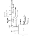
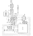
図1は本発明の第1実施例に係るDPF装置をそなえたディーゼルエンジンの排気装置の構成を示す系統図である。
図1において、ディーゼルエンジン1には図示しない過給機からの給気が給気通路7を通して供給され、該給気と燃料とによる燃焼後の排ガスは排気通路6を通して黒鉛除去装置即ちDPF(ディーゼルパティキュレートフィルタ)2に入る。該DPF2は、排ガス中の煤等の固形排出物(以下煤と総称する)を捕獲するフィルタをそなえ、該フィルタで捕獲した煤を燃焼させるもので、この発明では公知のDPFを用いることができる。
前記DPF2の下流側の排気通路6には還元触媒コンバータ3及び酸化触媒コンバータ4が列設され、前記DPF2で煤を除去された排ガスは、途中で尿素噴射システム5からの還元作用促進用尿素が混入されて還元触媒コンバータ3に導入される。
そして、排ガスは該還元触媒コンバータ3でNOxが除去された後、酸化触媒コンバータ4でHC,CO等が除去されてから、大気中に排出される。
FIG. 1 is a system diagram showing a configuration of an exhaust device of a diesel engine provided with a DPF device according to a first embodiment of the present invention.
In FIG. 1, a
A reduction
Then, after NOx is removed by the reduction
前記排気通路6のDPF2の上流部位からは、符号10で示されるDPFバイパス通路が分岐されて該DPF2をバイパスして、該DPF2の下流部位に接続されている。該DPFバイパス通路10の途中には、該DPFバイパス通路10を開閉するとともに通路面積を調整するDPFバイパス弁11が設置されている。
前記DPFバイパス弁11を、後述する手順で制御するコントローラは符号14で示され、該コントローラ14には、エンジン回転数検出器13から前記ディーゼルエンジン1のエンジン回転数の検出値が、負荷検出器12から前記ディーゼルエンジン1のエンジン負荷の検出値がそれぞれ入力される。
A DPF bypass passage indicated by
A controller for controlling the
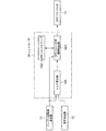
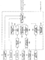
次に、図2に示すDPF装置の制御ブロック図に基づき、かかる第1実施例におけるDPFバイパス弁11の開閉制御について説明する。
図2において、前記エンジン回転数検出器13からのエンジン回転数の検出値及び負荷検出器12からのエンジン負荷の検出値は、前記コントローラ14のトルク算出部141に入力され、該トルク算出部141においては、前記エンジン回転数検出値及びエンジン負荷検出値に基づき現在のトルクを算出してDPFバイパス弁開閉判断部143に入力する。
Next, the opening / closing control of the
In FIG. 2, the detected value of the engine speed from the
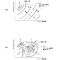
前記コントローラ14には、符号142で示されるDPFバイパス弁開度マップ(DPFバイパスマップ)がそなえられており、該DPFバイパス弁開度マップ142は、図3の(A),(B)に示されるように、エンジン回転数とエンジントルクに対応してディーゼルエンジン1の煤排出量とDPFバイパス弁11の開閉条件が設定されている。
かかるDPFバイパス弁開度マップ142は、対象エンジンと同形式のエンジンについてシミュレーション計算あるいは実験による算出結果に基づいて設定されたもので、図3(A)は煤排出量の比較的少ない運転条件における設定値、(B)は煤排出量の多い運転条件における設定値である。
The
The DPF bypass valve opening map 142 is set based on a simulation calculation or an experimental calculation result for an engine of the same type as the target engine. FIG. 3A shows an operation condition with a relatively small amount of soot emission. The set value, (B), is the set value under operating conditions with a large amount of soot discharge.
図3(A)の運転領域では、一点鎖線で示すDPFバイパス弁開閉ラインよりも高トルク、低回転数側で煤発生量が多くなった運転領域でDPFバイパス弁11を閉じてDPF2への排ガス流量を増加している。図(A),(B)において、最多煤発生量領域をZで示す。
図3(B)の運転領域では、一点鎖線で示すDPFバイパス弁開閉ラインが、あるエンジントルク及び回転数に集中しており、該DPFバイパス弁開閉ラインよりも図にZで示す最多煤発生量領域に近づく領域でDPFバイパス弁11を閉じてDPF2への排ガス流量を増加するようになっている。
3A, the
In the operation region of FIG. 3B, the DPF bypass valve opening / closing line indicated by the alternate long and short dash line is concentrated on a certain engine torque and rotation speed, and the maximum amount of occurrence of the soot indicated by Z in the drawing is greater than the DPF bypass valve opening / closing line. In the region approaching the region, the
前記DPFバイパス弁開閉判断部143においては、前記DPFバイパス弁開度マップ142と、前記トルク算出部141からのエンジントルク算出値及び前記エンジン回転数検出器13からのエンジン回転数検出値とを突き合わせて、前記エンジントルク及びエンジン回転数に対応するDPFバイパス弁11の開閉の区別を判定し、前記エンジン回転数及びエンジントルク(つまりエンジン負荷)において煤排出量がDPFバイパス弁11の開放条件となる煤排出量(つまり図3(A)、(B)におけるDPFバイパス弁開閉ライン)以下になったとき前記DPFバイパス弁11を開き、前記煤排出量を超えるようになったときDPFバイパス弁11を閉じる。
かかるDPFバイパス弁開閉判断部143からの判断信号によって、前記DPFバイパス弁11は開閉される。
In the DPF bypass valve opening /
The
かかる第1実施例によれば、コントローラ14において、エンジン回転数及びエンジン負荷(エンジントルク)とエンジン1の煤排出量との関係、並びに該煤排出量によるDPFバイパス弁11のDPFバイパス通路10の開閉条件を、シミュレーション計算あるいは実験によって最適値に予め設定したDPFバイパス弁開度マップ142を用いて、エンジン回転数及びエンジン負荷の検出値に基づき前記DPFバイパス弁開度マップ142からDPFバイパス弁11の適正開度を算出して、かかる適正開度によってDPFバイパス弁11を開閉制御するので、前記DPFバイパス弁開度マップ142に精緻に設定したエンジン回転数及びエンジン負荷等のエンジン運転条件とDPF2における煤除去機能及び圧力損失との最適関係によって、DPFバイパス弁11の開閉制御を行なうことにより、DPF2の煤除去機能を高く保持し且つDPF圧力損失を抑制した運転を行なうことが可能となる。
これにより、DPF2の排気抵抗を低減してエンジンの燃費を低減すると共に、DPF装置の耐久性を向上できる。
According to the first embodiment, in the
Thereby, the exhaust resistance of the
図4は本発明の第2実施例を示し、(A)は図1対応図、(B)はDPF圧損の変化を示す線図である。
図4において、前記排気通路6のDPF2入口側にはDPF入口の排ガス温度を検出するDPF入口排ガス温度センサ16が取り付けられ、前記排気通路6のDPF2出口側にはDPF出口の排ガス温度を検出するDPF出口排ガス温度センサ18が取り付けられ、DPF2の内部にはDPF内部温度センサ17が取り付けられており、前記DPF入口排ガス温度センサ16からのDPF入口排ガス温度検出値T1、DPF出口排ガス温度センサ18からのDPF出口排ガス温度検検出値T2、及びDPF内部温度センサ17からのDPF内部温度の検出値T3は前記コントローラ14に入力される。
また、前記排気通路6のDPF2出入口には、該DPF2の排ガス出入口間の差圧ΔPを検出するDPF差圧計15が取り付けられて、該DPF差圧計15からのDPF差圧の検出値ΔPは前記コントローラ14に入力される。
その他の構成は、図1に示される第1実施例と同様であり、これと同一の部材は同一の符号で示す。
4A and 4B show a second embodiment of the present invention, in which FIG. 4A is a diagram corresponding to FIG. 1 and FIG. 4B is a diagram showing changes in DPF pressure loss.
In FIG. 4, a DPF inlet exhaust
A DPF
Other configurations are the same as those of the first embodiment shown in FIG. 1, and the same members are denoted by the same reference numerals.
次に、図5に示すDPF装置の制御ブロック図に基づき、かかる第2実施例におけるDPFバイパス弁11の開閉制御について説明する。
前記DPF差圧計15からのDPF差圧の検出値ΔPは前記コントローラ14の圧損上昇率算出部に入力される。圧損上昇率算出部146においては、図4(B)に示すような単位時間当たりの圧損上昇率ΔΔP=dΔP/dtを算出して圧損判断部148に入力する。
さらに、前記DPF入口排ガス温度センサ16からのDPF入口排ガス温度検出値T1及び、DPF出口排ガス温度センサ18からのDPF出口排ガス温度検出値T2は前記コントローラ14のDPF出入口温度差算出部145に入力される。該DPF出入口温度差算出部145においては、前記DPF2出入口間の排ガス温度差ΔTを算出してDPF温度差算出部150に入力する。
Next, opening / closing control of the
The detected value ΔP of the DPF differential pressure from the DPF
Further, the DPF inlet exhaust gas temperature detection value T1 from the DPF inlet exhaust
また前記コントローラ14は基準圧損上昇率設定部147をそなえており、該基準圧損上昇率設定部147においては、DPF2における圧損上昇率の基準値である基準圧損上昇率つまりエンジンの煤発生量が少なくDPFバイパス弁11を開放可能とする圧損上昇率が設定されている。
そして前記圧損判断部148においては、前記圧損上昇率ΔΔPの算出値が、前記基準圧損上昇率以下のときはエンジンの煤発生量が少ないと判断して、DPFバイパス弁11を開放せしめてDPFへの排ガス流量を減少させる。
一方、前記圧損上昇率ΔΔPの算出値が、前記基準圧損上昇率を超えるときはエンジンの煤発生量が多いと判断して、DPFバイパス弁11を閉鎖あるいは開度を減少せしめてDPF2への排ガス流量を増加させ、該DPFにおける煤除去機能を上昇させる。
Further, the
In the pressure
On the other hand, if the calculated value of the pressure loss increase rate ΔΔP exceeds the reference pressure loss increase rate, it is determined that the amount of soot generated in the engine is large, and the
また前記コントローラ14は基準DPF出入口温度差設定部149をそなえており、該基準DPF出入口温度差設定部149においては、DPF2におけるDPF出入口温度差の基準値である基準DPF出入口温度差つまりエンジンの煤発生量が少なくDPFバイパス弁11を開放可能とするDPF出入口温度差が設定されている。
そして前記DPF温度差判断部150においては、DPF出入口間排ガス温度差ΔTの算出値が前記基準DPF出入口温度差以下のときは、DPF2での煤除去作用が小さいと判断してDPFバイパス弁11を開放せしめてDPF2の排ガス流量を減少させる。
一方、前記排ガス出入口温度差ΔTが前記基準DPF出入口温度差を超えるときには、DPF2での煤除去作用が活発と判断して、DPFバイパス弁11を閉鎖あるいは開度を減少せしめてDPF2への排ガス流量を増加させる。
In addition, the
In the DPF temperature
On the other hand, when the exhaust gas inlet / outlet temperature difference ΔT exceeds the reference DPF inlet / outlet temperature difference, it is determined that the soot removing action in the
また前記コントローラ14は基準DPF内部温度設定部151をそなえており、該基準DPF内部温度設定部151においては、DPF2におけるDPF内部温度の基準値である基準DPF内部温度、つまりDPF内部温度の上昇が小さくDPFバイパス弁11を開放可能とするDPF内部温度が設定されている。
そしてDPF内部温度判断部152においては、前記DPF内部温度センサ17からのDPF内部温度の検出値T3が前記基準DPF内部温度以下のときはDPF2での煤除去作用が小さいと判断して、DPFバイパス弁11を開放せしめてDPF2の排ガス流量を減少させる。
一方、前記DPF内部温度の検出値T3が前記基準DPF内部温度を超えたときにはDPF2での煤除去作用が活発と判断して、DPFバイパス弁11を閉鎖あるいは開度を減少せしめてDP2Fへの排ガス流量を増加させる。
Further, the
The DPF internal
On the other hand, when the detected value T3 of the DPF internal temperature exceeds the reference DPF internal temperature, it is determined that the soot removal action in the
前記圧損判断部148からの圧損上昇率判断結果、DPF温度差判断部150からのDPF出入口間排ガス温度差判断結果、及びDPF内部温度判断部152からのDPF内部温度の判断結果はDPFバイパス弁開閉判断部143に入力される。
該DPFバイパス弁開閉判断部143においては、圧損上昇率ΔΔPの算出値が基準圧損上昇率以下のときは、エンジンの煤発生量が少ないと判断してDPFバイパス弁11を開放せしめてDPFへの排ガス流量を減少させ、圧損上昇率ΔΔPの算出値が基準圧損上昇率を超えるときは、エンジンの煤発生量が多いと判断して、DPFバイパス弁11を閉鎖あるいは開度を減少せしめてDPF2への排ガス流量を増加させ該DPFにおける煤除去機能を上昇させる。
The pressure loss increase rate determination result from the pressure
In the DPF bypass valve opening /
またDPFバイパス弁開閉判断部143においては、
前記圧損上昇率ΔΔPの算出値が前記基準圧損上昇率以下で、且つ前記DPF出入口間排ガス温度差ΔTの算出値が前記基準DPF出入口温度差以下で、且つDPF内部温度の検出値T3が前記基準DPF内部温度以下の3つの条件を満足したときは、DPF2での煤除去作用が小さいと判断して、DPFバイパス弁11を開放せしめてDPF2の排ガス流量を減少させる。
一方、前記圧損上昇率ΔΔPの算出値が前記基準圧損上昇率を超え、且つ前記DPF出入口間排ガス温度差ΔTの算出値が前記基準DPF出入口温度差を超え、且つDPF内部温度の検出値T3が前記基準DPF内部温度を超える3つの条件を満足したときは、エンジンの煤発生量が多いと判断して、DPFバイパス弁11を閉鎖あるいは開度を減少せしめてDPF2への排ガス流量を増加させ、該DPFにおける煤除去機能を上昇させる。
In the DPF bypass valve open /
The calculated value of the pressure loss increase rate ΔΔP is less than or equal to the reference pressure loss increase rate, the calculated value of the exhaust gas temperature difference ΔT between the DPF ports is equal to or less than the reference DPF port temperature difference, and the detected value T3 of the DPF internal temperature is the reference value When the three conditions below the DPF internal temperature are satisfied, it is determined that the soot removing action of the
On the other hand, the calculated value of the pressure loss increase rate ΔΔP exceeds the reference pressure loss increase rate, the calculated value of the exhaust gas temperature difference ΔT between the DPF inlets and outlets exceeds the reference DPF inlet / outlet temperature difference, and the detected value T3 of the DPF internal temperature is When the three conditions exceeding the reference DPF internal temperature are satisfied, it is determined that the amount of soot generation in the engine is large, and the
以上の第2実施例によれば、DPFバイパス弁11の開閉制御にDPF2における圧損(圧力損失)上昇率ΔΔPを取り入れ、この圧損上昇率ΔΔPが前記基準圧損上昇率以下のときはエンジンの煤発生量が少ないと判断してDPFバイパス弁を開放せしめてDPF2への排ガス流量を減少させ、前記圧損上昇率ΔΔPが前記基準圧損上昇率超えるときはエンジンの煤発生量が多いと判断してDPFバイパス弁11を閉鎖あるいは開度を減少せしめてDPFへの排ガス流量を増加させ、DPF2における煤除去機能を上昇させることにより、常時DPF2の煤除去機能を高く保持し且つDPF圧力損失を許容値以下に抑制した運転を行なうことが可能となる。
殊に、DPFバイパス弁11の開閉制御に、DPF2における圧損上昇率ΔΔPを取り入れたことによって、DPF圧損の急変化に迅速に対応してDPF2の排ガス流量を変化させることが可能となって、DPF2の排ガス流量制御の応答性が向上する。
According to the second embodiment described above, the pressure loss (pressure loss) increase rate ΔΔP in the
In particular, by incorporating the pressure loss increase rate ΔΔP in the
また、かかる第2実施例によれば、DPFバイパス弁11の開閉制御に、DPF2における圧損上昇率ΔΔPに加えて、DPFにおける排ガスの出入口温度差ΔT及びDPF2の内部温度T3を取り入れたことにより、DPF圧損の急変化に迅速に対応してDPF2の排ガス流量を変化させることが可能となって、DPF2の排ガス流量制御の応答性が向上するとともに、排ガスの出入口温度差ΔT及びDPFの内部温度T3によってDPF2の煤除去作用状態を検知して、該DPF2における排ガス流量を行なうことにより、DPF2の排ガス流量制御の精度が向上する。
Further, according to the second embodiment, in addition to the pressure loss increase rate ΔΔP in the
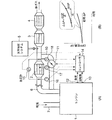
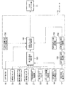
図6は、本発明の第3実施例を示す図1対応図である。
かかる第3実施例は、図4に示される第2実施例に、エンジン1の給気圧力を検出する給気圧センサ23、給気温度を検出する給気温度センサ24、給気量を検出する給気量センサ25、燃料噴射量を検出する燃料噴射量検出器21、前記DPF2の上流の排ガス圧力を検出する排ガス圧力センサ22、DPFバイパス弁11の開度を検出するバイパス弁開度検出器20を追設し、これら各センサ(検出器)の検出値を前記コントローラ14に入力して、後述する演算、制御を行なっている。
その他の構成は、前記第1実施例(図1)あるいは第2実施例(図4)と同様であり、これらと同一の部材は同一の符号で示す。
FIG. 6 is a view corresponding to FIG. 1 showing a third embodiment of the present invention.
The third embodiment is similar to the second embodiment shown in FIG. 4 in that a supply
Other configurations are the same as those of the first embodiment (FIG. 1) or the second embodiment (FIG. 4), and the same members are denoted by the same reference numerals.
次に、図7に示すDPF装置の制御ブロック図に基づき、かかる第3実施例におけるDPFバイパス弁11の開閉制御について説明する。
前記給気圧センサ23からの給気圧力検出値、給気温度センサ24からの給気温度検出値、給気量センサ25からの給気量検出値、燃料噴射量検出器21からの燃料噴射量検出値、前記排ガス圧力センサ22からの排ガス圧力検出値、バイパス弁開度検出器20からのDPFバイパス弁開度検出値、及びDPF排ガス入口温度センサ16からのDPF排ガス入口温度検出値は、前記コントローラ14の排ガス流量算出部155に入力される。
該排ガス流量算出部155においては、前記各検出値を用いて(各検出値の一部を用いてもよい)排ガス流量を算出して、DPFバイパス弁開閉判断部143に入力する。
Next, opening / closing control of the
An air supply pressure detection value from the air
The exhaust gas flow
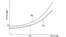
156は圧力損失/排ガス流量設定部156で、図8にW1線で示される排ガス流量〜DPF圧力損失〜バイパス弁開度の関係が予め設定されており、排ガス流量〜DPF圧力損失の関係がW2線よりも上方領域になったときDPFバイパス弁11を閉とし、それよりも下の領域ではDPFバイパス弁11を開とするように設定されている。
DPFバイパス弁開閉判断部143においては、前記排ガス流量の算出値(たとえばQex)と前記DPF差圧計15からのDPF差圧(圧力損失)検出値を図8に示される排ガス流量〜DPF圧力損失〜バイパス弁開度線図に対応させて、DPFバイパス弁11の開閉を決定し、該DPFバイパス弁11を開閉せしめる。
156 is a pressure loss / exhaust gas flow
In the DPF bypass valve opening /
このように構成すれば、DPF2の再生時等において、該DPF2の差圧ΔPが基準値(つまり図8におけるW2ライン)を超えた場合、DPFバイパス弁11を閉じて、DPF2への排ガス流量を増加して、DPF2から熱を取り去ることにより、DPF2の過熱による溶損の発生を防止できる。
With this configuration, when the differential pressure ΔP of the DPF 2 exceeds a reference value (that is, the W 2 line in FIG. 8) during regeneration of the DPF 2 , the
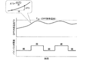
一方、前記第2実施例と同様なDPF内部温度センサ17からのDPF内部温度の検出値T3は、前記コントローラ14のDPF温度上昇率算出部158に入力される。DPF温度上昇率算出部158においては、図9に示すDPF温度変化線図のように、DPF内部温度の検出値T3に基づきDPF温度上昇率ΔT3を算出しDPF温度上昇率判断部160に入力する。
159はDPF温度上昇率設定部で、DPF温度上昇率の許容値つまり図9におけるDPF耐熱温度T30が設定されている。
前記DPF温度上昇率判断部160においては、前記DPF温度上昇率ΔT3が、DPF温度上昇率設定部159に設定されているDPF温度上昇率の許容値を超えるとき、前記DPFバイパス弁11を閉じ、前記DPF温度上昇率の許容値以下のとき前記DPFバイパス弁11を開くように、該DPFバイパス弁11を開閉制御する。
On the other hand, the DPF internal temperature detection value T3 from the DPF
Reference numeral 159 denotes a DPF temperature increase rate setting unit, in which an allowable value of the DPF temperature increase rate, that is, the DPF heat resistant temperature T30 in FIG. 9 is set.
In the DPF temperature increase
このように構成すれば、DPF2に基準温度上昇率つまりDPF温度上昇率の許容値を超える急激な温度上昇があった場合には、DPFバイパス弁11を閉じてDPF2への排ガス流量を増加して、該DPF2から熱を取り去ることによりDPF2の温度上昇を抑制することにより、DPF2の過熱による溶損の発生を防止できる。
With this configuration, when the
本発明によれば、エンジン回転数、エンジン負荷等のエンジン運転条件とDPFにおける煤除去機能及び圧力損失との最適関係を精緻に設定するとともに、DPF出入口の排気温度、DPF自体の温度等の広範囲の制御因子によってDPFを通る排ガス量及びDPFの作動を高精度に制御可能として、排気抵抗を低減してエンジンの燃費を低減すると共に、DPF装置の耐久性を向上したDPF装置をそなえたエンジンの排気装置を提供できる。 According to the present invention, the optimum relationship between engine operating conditions such as engine speed and engine load, soot removal function and pressure loss in the DPF is precisely set, and a wide range of exhaust temperature of the DPF inlet / outlet, temperature of the DPF itself, etc. It is possible to control the amount of exhaust gas passing through the DPF and the operation of the DPF with high accuracy by the control factor of the engine, reducing the exhaust resistance, reducing the fuel consumption of the engine, and improving the durability of the DPF device. An exhaust device can be provided.
1 ディーゼルエンジン
2 DPF(ディーゼルパティキュレートフィルタ)プランジャ
3 還元触媒コンバータ
4 酸化触媒コンバータ
6 排気通路
7 給気通路
10 DPFバイパス通路
11 DPFバイパス弁
12 負荷検出器
13 エンジン回転数検出器
14 コントローラ
15 DPF差圧計
16 DPF入口排ガス温度センサ
17 DPF内部温度センサ
18 DPF出口排ガス温度センサ
DESCRIPTION OF
Claims (6)
In an engine having a black smoke removal device (DPF) that captures solid emissions such as soot in exhaust gas in an exhaust passage, the exhaust passage is branched from an upstream portion of the black smoke removal device, and the black smoke removal device A DPF bypass passage connected to the downstream portion, a DPF bypass valve for opening and closing the DPF bypass passage and adjusting the passage area, and a temperature rise of the black smoke removal device based on a detected value of the internal temperature in the black smoke removal device A temperature rise rate calculating means for calculating a rate is provided, and a DPF device is provided that includes a controller that closes the DPF bypass valve when the temperature rise rate exceeds a preset reference temperature rise rate. Engine exhaust system.
Priority Applications (1)
| Application Number | Priority Date | Filing Date | Title |
|---|---|---|---|
| JP2006324638A JP4969225B2 (en) | 2006-11-30 | 2006-11-30 | Engine exhaust system with DPF device |
Applications Claiming Priority (1)
| Application Number | Priority Date | Filing Date | Title |
|---|---|---|---|
| JP2006324638A JP4969225B2 (en) | 2006-11-30 | 2006-11-30 | Engine exhaust system with DPF device |
Publications (2)
| Publication Number | Publication Date |
|---|---|
| JP2008138564A true JP2008138564A (en) | 2008-06-19 |
| JP4969225B2 JP4969225B2 (en) | 2012-07-04 |
Family
ID=39600305
Family Applications (1)
| Application Number | Title | Priority Date | Filing Date |
|---|---|---|---|
| JP2006324638A Expired - Fee Related JP4969225B2 (en) | 2006-11-30 | 2006-11-30 | Engine exhaust system with DPF device |
Country Status (1)
| Country | Link |
|---|---|
| JP (1) | JP4969225B2 (en) |
Cited By (3)
| Publication number | Priority date | Publication date | Assignee | Title |
|---|---|---|---|---|
| US20120124977A1 (en) * | 2010-11-19 | 2012-05-24 | Hyundai Motor Company | Exhaust gas post processing system |
| JP2013104380A (en) * | 2011-11-15 | 2013-05-30 | Mitsubishi Motors Corp | Regenerating device of exhaust emission control device |
| CN113294227A (en) * | 2021-07-01 | 2021-08-24 | 南昌智能新能源汽车研究院 | Device for improving SDPF low-temperature starting performance and control method thereof |
Families Citing this family (2)
| Publication number | Priority date | Publication date | Assignee | Title |
|---|---|---|---|---|
| KR101601426B1 (en) * | 2014-06-03 | 2016-03-21 | 현대자동차주식회사 | DEVICE AND METHOD FOR CONTROLLING RECYCLE OF Diesel Particular Filter |
| US10273847B2 (en) * | 2017-05-26 | 2019-04-30 | GM Global Technology Operations LLC | Systems and methods for controlling bypass of exhaust after treatment device |
Citations (7)
| Publication number | Priority date | Publication date | Assignee | Title |
|---|---|---|---|---|
| JPH0240017A (en) * | 1988-07-29 | 1990-02-08 | Isuzu Motors Ltd | Recombustion device of particulate trap |
| JPH0544428A (en) * | 1991-08-09 | 1993-02-23 | Nissan Motor Co Ltd | Exhaust gas purifying device for internal combustion engine |
| JPH05332127A (en) * | 1992-05-29 | 1993-12-14 | Nissan Motor Co Ltd | Reproducing unit for exhaust gas filter |
| JPH09137716A (en) * | 1995-11-15 | 1997-05-27 | Toyota Motor Corp | Exhaust gas purification device for internal combustion engine |
| JPH10266826A (en) * | 1997-03-21 | 1998-10-06 | Nippon Soken Inc | Exhaust gas treatment equipment for diesel engines |
| JP2002349241A (en) * | 2001-05-24 | 2002-12-04 | Isuzu Motors Ltd | Diesel engine exhaust purification system |
| JP2003286834A (en) * | 2002-03-28 | 2003-10-10 | Nissan Diesel Motor Co Ltd | Exhaust unit of diesel engine |
-
2006
- 2006-11-30 JP JP2006324638A patent/JP4969225B2/en not_active Expired - Fee Related
Patent Citations (7)
| Publication number | Priority date | Publication date | Assignee | Title |
|---|---|---|---|---|
| JPH0240017A (en) * | 1988-07-29 | 1990-02-08 | Isuzu Motors Ltd | Recombustion device of particulate trap |
| JPH0544428A (en) * | 1991-08-09 | 1993-02-23 | Nissan Motor Co Ltd | Exhaust gas purifying device for internal combustion engine |
| JPH05332127A (en) * | 1992-05-29 | 1993-12-14 | Nissan Motor Co Ltd | Reproducing unit for exhaust gas filter |
| JPH09137716A (en) * | 1995-11-15 | 1997-05-27 | Toyota Motor Corp | Exhaust gas purification device for internal combustion engine |
| JPH10266826A (en) * | 1997-03-21 | 1998-10-06 | Nippon Soken Inc | Exhaust gas treatment equipment for diesel engines |
| JP2002349241A (en) * | 2001-05-24 | 2002-12-04 | Isuzu Motors Ltd | Diesel engine exhaust purification system |
| JP2003286834A (en) * | 2002-03-28 | 2003-10-10 | Nissan Diesel Motor Co Ltd | Exhaust unit of diesel engine |
Cited By (3)
| Publication number | Priority date | Publication date | Assignee | Title |
|---|---|---|---|---|
| US20120124977A1 (en) * | 2010-11-19 | 2012-05-24 | Hyundai Motor Company | Exhaust gas post processing system |
| JP2013104380A (en) * | 2011-11-15 | 2013-05-30 | Mitsubishi Motors Corp | Regenerating device of exhaust emission control device |
| CN113294227A (en) * | 2021-07-01 | 2021-08-24 | 南昌智能新能源汽车研究院 | Device for improving SDPF low-temperature starting performance and control method thereof |
Also Published As
| Publication number | Publication date |
|---|---|
| JP4969225B2 (en) | 2012-07-04 |
Similar Documents
| Publication | Publication Date | Title |
|---|---|---|
| JP4400356B2 (en) | Exhaust gas purification device for internal combustion engine | |
| JP5708584B2 (en) | Control device for internal combustion engine | |
| JP2010031833A (en) | Exhaust emission control device for diesel engine | |
| US8549843B2 (en) | Method of controlling exhaust gas purification system and exhaust gas purification system | |
| WO2017073799A1 (en) | Exhaust gas purification system and exhaust gas purification method | |
| JP2006161718A (en) | Exhaust gas purification system for internal combustion engine | |
| EP1555401B1 (en) | Exhaust purifying apparatus for internal combustion engine | |
| CN101052787B (en) | Exhaust gas purification system for internal combustion engine | |
| US11293320B2 (en) | Control device, exhaust gas purification system, and control method of engine | |
| JP4311071B2 (en) | Defect determination method of exhaust purification system | |
| WO2016125738A1 (en) | Exhaust gas purification system for internal combustion engine, internal combustion engine, and exhaust gas purification method for internal combustion engine | |
| JP4969225B2 (en) | Engine exhaust system with DPF device | |
| US7950225B2 (en) | Exhaust control system for an internal combustion engine | |
| JP4305402B2 (en) | Exhaust gas purification device for internal combustion engine | |
| JP6729473B2 (en) | Filter regeneration control device and filter regeneration control method | |
| JP2010077894A (en) | Dpf regeneration control device | |
| JP4033189B2 (en) | Exhaust gas purification device for internal combustion engine | |
| JP4613787B2 (en) | Exhaust gas purification device for internal combustion engine | |
| JP2020023955A (en) | Control device, exhaust gas purification system and control method | |
| JP4248415B2 (en) | Exhaust gas purification system for internal combustion engine | |
| JP4533832B2 (en) | Exhaust gas purification device | |
| JP5091977B2 (en) | Exhaust gas purification device | |
| JP2008050946A (en) | Exhaust gas recirculation system for internal combustion engine | |
| JP4525147B2 (en) | Engine exhaust purification system | |
| JP4325580B2 (en) | Control device for internal combustion engine |
Legal Events
| Date | Code | Title | Description |
|---|---|---|---|
| A621 | Written request for application examination |
Free format text: JAPANESE INTERMEDIATE CODE: A621 Effective date: 20090115 |
|
| A977 | Report on retrieval |
Free format text: JAPANESE INTERMEDIATE CODE: A971007 Effective date: 20101130 |
|
| A131 | Notification of reasons for refusal |
Free format text: JAPANESE INTERMEDIATE CODE: A131 Effective date: 20101203 |
|
| RD02 | Notification of acceptance of power of attorney |
Free format text: JAPANESE INTERMEDIATE CODE: A7422 Effective date: 20101222 |
|
| A521 | Written amendment |
Free format text: JAPANESE INTERMEDIATE CODE: A523 Effective date: 20110201 |
|
| A131 | Notification of reasons for refusal |
Free format text: JAPANESE INTERMEDIATE CODE: A131 Effective date: 20110826 |
|
| A521 | Written amendment |
Free format text: JAPANESE INTERMEDIATE CODE: A523 Effective date: 20111025 |
|
| TRDD | Decision of grant or rejection written | ||
| A01 | Written decision to grant a patent or to grant a registration (utility model) |
Free format text: JAPANESE INTERMEDIATE CODE: A01 Effective date: 20120316 |
|
| A01 | Written decision to grant a patent or to grant a registration (utility model) |
Free format text: JAPANESE INTERMEDIATE CODE: A01 |
|
| A61 | First payment of annual fees (during grant procedure) |
Free format text: JAPANESE INTERMEDIATE CODE: A61 Effective date: 20120403 |
|
| FPAY | Renewal fee payment (event date is renewal date of database) |
Free format text: PAYMENT UNTIL: 20150413 Year of fee payment: 3 |
|
| FPAY | Renewal fee payment (event date is renewal date of database) |
Free format text: PAYMENT UNTIL: 20150413 Year of fee payment: 3 |
|
| R250 | Receipt of annual fees |
Free format text: JAPANESE INTERMEDIATE CODE: R250 |
|
| LAPS | Cancellation because of no payment of annual fees |