JP2008129608A - Zoom lens - Google Patents
Zoom lens Download PDFInfo
- Publication number
- JP2008129608A JP2008129608A JP2007303671A JP2007303671A JP2008129608A JP 2008129608 A JP2008129608 A JP 2008129608A JP 2007303671 A JP2007303671 A JP 2007303671A JP 2007303671 A JP2007303671 A JP 2007303671A JP 2008129608 A JP2008129608 A JP 2008129608A
- Authority
- JP
- Japan
- Prior art keywords
- lens
- object side
- lens group
- zoom
- refractive power
- Prior art date
- Legal status (The legal status is an assumption and is not a legal conclusion. Google has not performed a legal analysis and makes no representation as to the accuracy of the status listed.)
- Pending
Links
Images


Classifications
-
- G—PHYSICS
- G02—OPTICS
- G02B—OPTICAL ELEMENTS, SYSTEMS OR APPARATUS
- G02B15/00—Optical objectives with means for varying the magnification
- G02B15/14—Optical objectives with means for varying the magnification by axial movement of one or more lenses or groups of lenses relative to the image plane for continuously varying the equivalent focal length of the objective
- G02B15/142—Optical objectives with means for varying the magnification by axial movement of one or more lenses or groups of lenses relative to the image plane for continuously varying the equivalent focal length of the objective having two groups only
- G02B15/1425—Optical objectives with means for varying the magnification by axial movement of one or more lenses or groups of lenses relative to the image plane for continuously varying the equivalent focal length of the objective having two groups only the first group being negative
-
- G—PHYSICS
- G02—OPTICS
- G02B—OPTICAL ELEMENTS, SYSTEMS OR APPARATUS
- G02B13/00—Optical objectives specially designed for the purposes specified below
- G02B13/001—Miniaturised objectives for electronic devices, e.g. portable telephones, webcams, PDAs, small digital cameras
- G02B13/009—Miniaturised objectives for electronic devices, e.g. portable telephones, webcams, PDAs, small digital cameras having zoom function
-
- G—PHYSICS
- G02—OPTICS
- G02B—OPTICAL ELEMENTS, SYSTEMS OR APPARATUS
- G02B3/00—Simple or compound lenses
- G02B3/0087—Simple or compound lenses with index gradient
-
- G—PHYSICS
- G02—OPTICS
- G02B—OPTICAL ELEMENTS, SYSTEMS OR APPARATUS
- G02B3/00—Simple or compound lenses
- G02B3/02—Simple or compound lenses with non-spherical faces
- G02B3/04—Simple or compound lenses with non-spherical faces with continuous faces that are rotationally symmetrical but deviate from a true sphere, e.g. so called "aspheric" lenses
-
- G—PHYSICS
- G02—OPTICS
- G02B—OPTICAL ELEMENTS, SYSTEMS OR APPARATUS
- G02B3/00—Simple or compound lenses
- G02B2003/0093—Simple or compound lenses characterised by the shape
Abstract
Description
本発明は、ズームレンズに関するものである。 The present invention relates to a zoom lens.
最近、携帯電話や移動通信端末機にCCDまたはCMOSのような固体撮像素子を用いたコンパクトなデジタルカメラやデジタルビデオカメラが内蔵されている。このような撮像素子は小型化する趨勢であり、これによって撮像素子に備えられるズームレンズに対しても小型化が要求されている。 Recently, a compact digital camera or digital video camera using a solid-state image sensor such as a CCD or a CMOS is built in a mobile phone or a mobile communication terminal. Such an image sensor has a tendency to be miniaturized, and accordingly, a zoom lens provided in the image sensor is also required to be miniaturized.
本発明に係るズームレンズは小型化を具現することをその目的とする。 It is an object of the zoom lens according to the present invention to realize miniaturization.
また、本発明の他の目的は、収差特性が良好で、かつ量産性が改善されたズームレンズを提供することにある。 Another object of the present invention is to provide a zoom lens with good aberration characteristics and improved mass productivity.
本発明のある態様に係るズームレンズは、物体側に位置して負の屈折力を有する第1レンズ群と、像側に位置して正の屈折力を有する第2レンズ群とを含み、上記第1レンズ群と第2レンズ群との間の間隔が変化されるにつれてズーミングが行なわれて、次の条件式を満たす。
−4<f1/Zr<−0.5
(但し、f1は第1レンズ群の焦点距離、Zrは広角端での全体焦点距離と望遠端での全体焦点距離の比(ft/fw)を示す。)
A zoom lens according to an aspect of the present invention includes a first lens group having a negative refractive power located on the object side and a second lens group having a positive refractive power located on the image side, As the distance between the first lens group and the second lens group is changed, zooming is performed and the following conditional expression is satisfied.
-4 <f1 / Zr <-0.5
(Where f1 is the focal length of the first lens group, and Zr is the ratio (ft / fw) of the total focal length at the wide angle end to the total focal length at the telephoto end.)
本発明の別の態様に係るズームレンズは、物体側に位置して負の屈折力を有する第1レンズ群と、像側に位置して正の屈折力を有する第2レンズ群とを含み、上記第1レンズ群と第2レンズ群との間の間隔が変化されるにつれてズーミングが行なわれて、次の条件式を満たす。
−1<f1/ttlw<−0.15
(但し、f1は第1レンズ群の焦点距離、ttlwは広角端の全長を示す。)
A zoom lens according to another aspect of the present invention includes a first lens group having negative refractive power located on the object side, and a second lens group having positive refractive power located on the image side, As the distance between the first lens group and the second lens group is changed, zooming is performed and the following conditional expression is satisfied.
−1 <f1 / ttlw <−0.15
(Where f1 is the focal length of the first lens group, and tlw is the total length of the wide-angle end.)
本発明によるズームレンズは小型化を具現することができる。 The zoom lens according to the present invention can be miniaturized.
また、本発明は、収差特性が良好で、かつ量産性が改善されたズームレンズを提供することができる。 In addition, the present invention can provide a zoom lens having good aberration characteristics and improved mass productivity.
添付した図面を参考しつつ本発明の実施形態を詳細に説明する。 Embodiments of the present invention will be described in detail with reference to the accompanying drawings.
図1は、本発明の実施形態に係るズームレンズを概略的に示す側断面図である。 FIG. 1 is a side sectional view schematically showing a zoom lens according to an embodiment of the present invention.
本実施形態において、ズームレンズは、第1レンズ群100と第2レンズ群200とからなる。
In the present embodiment, the zoom lens includes a
第1レンズ群100は物体側に位置し、負の屈折力を持っており、物体側に凸面が向かう負レンズを含む。
The
第1レンズ群100は、第1レンズ110と第2レンズ120とを含み、物体側から像側方向に順次に第1レンズ110と第2レンズ120が位置する。
The
第1レンズ110は、凸面が物体側に位置して負の屈折力を有し、第2レンズ120は凸面が物体側に位置して正の屈折力を有する。第1レンズ群100は全体として負の屈折力を有する。
The
第2レンズ群200は、像側に位置し、負の屈折力を持っており、物体側に凸面が向かい、少なくとも一面が非球面で構成された正のレンズを含む。
The
第2レンズ群200は、物体側から像側方向に順次に、絞り205、第3レンズ210、第4レンズ220、第5レンズ230、及び第6レンズ240が位置する。
In the
第3レンズ210及び第4レンズ220は、凸面が物体側に位置して正の屈折力を有し、第5レンズ230は像側に凹面を持って負の屈折力を有し、第6レンズ240は物体側に凸面が位置して正の屈折力を有する。
The
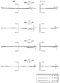
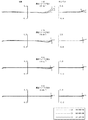
図2は、本発明の実施形態に係るズームレンズのズーム動作を示す図である。 FIG. 2 is a diagram illustrating a zoom operation of the zoom lens according to the embodiment of the present invention.
図2(a)は広角端(wide)でのズームレンズの形態であり、図2(b)は標準端(normal)でのズームレンズの形態であり、図2(c)は望遠端(tele)でのズームレンズの形態である。 2A shows a zoom lens configuration at the wide-angle end (wide), FIG. 2B shows a zoom lens configuration at the normal end, and FIG. 2C shows a telephoto end (tele). ) In the form of a zoom lens.
本実施形態では第1レンズ群100と第2レンズ群200との間の間隔が変化されるにつれてズーミング(変倍)が行なわれる。
In the present embodiment, zooming (magnification) is performed as the distance between the
本実施形態では第1実施形態及び第2実施形態を提案する。 In the present embodiment, the first embodiment and the second embodiment are proposed.
第1実施形態は、表1に図示されたズームパラメータ値を有する。 The first embodiment has the zoom parameter values illustrated in Table 1.

表1において、aは第2レンズ120と第3レンズ210との間の距離を表し、bは第6レンズ240と像面との間の距離を表す。
In Table 1, a represents the distance between the
表2は、ズームレンズを構成する要素の数値データを表す。 Table 2 shows numerical data of elements constituting the zoom lens.
表2において、曲率半径は光学面の曲率半径を表し、厚みは光学面の厚みを表し、曲率半径と光学面の単位はmmである。 In Table 2, the radius of curvature represents the radius of curvature of the optical surface, the thickness represents the thickness of the optical surface, and the unit of the radius of curvature and the optical surface is mm.
また、レンズ面番号は物体側から像側方向に順次に表示したものである。 The lens surface numbers are sequentially displayed from the object side to the image side.
この際、第1実施形態に係るズームレンズは、R4、R9及びR13面が非球面であるレンズを含む。 At this time, the zoom lens according to the first embodiment includes lenses in which the R4, R9, and R13 surfaces are aspherical surfaces.
本実施形態において、非球面定義式は次の通りである。 In the present embodiment, the aspheric definition formula is as follows.
![]()
![]()
非球面定義式は、第1実施形態と第2実施形態で同一に使われる。 The aspheric definition formula is used in the same way in the first embodiment and the second embodiment.
次の表3は各非球面に対する非球面係数の数値を表す。 Table 3 below shows the numerical value of the aspheric coefficient for each aspheric surface.
表3において、R4、R9、R13はレンズ面の番号を表す。 In Table 3, R4, R9, and R13 represent lens surface numbers.
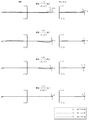
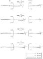
図3と図4は第1実施形態に係る広角端(wide)での収差グラフであり、図5と図6は第1実施形態に係る標準端(normal)での収差グラフであり、図7と図8は第1実施形態に係る望遠端(tele)での収差グラフである。 3 and 4 are aberration graphs at the wide-angle end (wide) according to the first embodiment, and FIGS. 5 and 6 are aberration graphs at the standard end (normal) according to the first embodiment. FIG. 8 is an aberration graph at the telephoto end (tele) according to the first embodiment.
各々縦側球面収差(longitudinal spherical aberration)、非点収差(astigmatic aberration)、歪曲収差、コマ(Coma)収差が図示されている。 Longitudinal spherical aberration, astigmatic aberration, distortion and coma aberration are shown in the figure.
次に、第2実施形態において、ズームパラメータの値は表4に表されている。 Next, zoom parameter values are shown in Table 4 in the second embodiment.
表4において、aは第2レンズ120と第3レンズ210との間の距離を表し、bは第6レンズ240と像面との間の距離を表す。
In Table 4, a represents the distance between the
次に図示された表5は、ズームレンズを構成する要素の数値データを表す。 Next, Table 5 shown represents numerical data of elements constituting the zoom lens.
表6は、ズームレンズを構成する要素の数値データを表す。 Table 6 shows numerical data of elements constituting the zoom lens.
表6において、曲率半径は光学面の曲率半径を表し、厚みは光学面の厚みを表し、曲率半径と光学面の単位はmmである。 In Table 6, the radius of curvature represents the radius of curvature of the optical surface, the thickness represents the thickness of the optical surface, and the unit of the radius of curvature and the optical surface is mm.
また、レンズ面番号は、物体側から像側方向に順次に表示したものである。 The lens surface numbers are sequentially displayed from the object side to the image side direction.
この際、第2実施形態に係るズームレンズは、R6、R11面が非球面であるレンズを含む。 At this time, the zoom lens according to the second embodiment includes lenses having R6 and R11 surfaces that are aspherical.
次の表6は、各非球面に対する非球面係数の数値を表す。 Table 6 below shows the numerical value of the aspheric coefficient for each aspheric surface.
表6において、R6、R11はレンズ面の番号を表す。 In Table 6, R6 and R11 represent lens surface numbers.
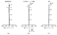
図9と図10は第2実施形態に係る広角端での収差グラフであり、図11と図12は第2実施形態に係る標準端での収差グラフであり、図13と図14は第2実施形態に係る望遠端での収差グラフである。各々縦側球面収差(longitudinal spherical aberration)、非点収差(astigmatic aberration)、歪曲収差、コマ(Coma)収差が図示されている。 FIGS. 9 and 10 are aberration graphs at the wide-angle end according to the second embodiment, FIGS. 11 and 12 are aberration graphs at the standard end according to the second embodiment, and FIGS. It is an aberration graph at the telephoto end according to the embodiment. Longitudinal spherical aberration, astigmatic aberration, distortion and coma aberration are shown in the figure.
上記縦側球面収差はRGB(Red、Green、Blue)に従う収差特性が図示されており、上記非点収差は接線(Tangential)、及びサジタル(Sagittal)に従い収差特性が図示されており、上記コマ収差は、波長(X、Y、Z)に従う接線及びサジタルでの収差特性が図示されている。 The longitudinal spherical aberration has an aberration characteristic according to RGB (Red, Green, Blue), and the astigmatism has an aberration characteristic according to a tangent and sagittal, and the coma aberration. Fig. 2 shows tangential and sagittal aberration characteristics according to wavelengths (X, Y, Z).
各実施形態の条件式は、次の表7の通りである。 The conditional expressions of each embodiment are as shown in Table 7 below.
表7において、Zrは広角端での全体焦点距離と望遠端での全体焦点距離の比(ft/fw)、f1は第1レンズ群焦点距離、f2は第2レンズ群焦点距離、ftは望遠端焦点距離、fwは広角端焦点距離、ttlwは広角端全長、ttltは望遠端全長を表す。
このような実施形態に係るズームレンズは、次の条件を満すことができる。
In Table 7, Zr is the ratio of the total focal length at the wide-angle end to the total focal length at the telephoto end (ft / fw), f1 is the first lens group focal length, f2 is the second lens group focal length, and ft is telephoto. The end focal length, fw is the wide-angle end focal length, ttlw is the wide-angle end total length, and ttlt is the telephoto end total length.
The zoom lens according to such an embodiment can satisfy the following conditions.
数2
−4<f1/Zr<−0.5
(但し、f1は第1レンズ群の焦点距離、Zrは広角端での全体焦点距離と望遠端での全体焦点距離の比(ft/fw)を示す。)
-4 <f1 / Zr <-0.5
(Where f1 is the focal length of the first lens group, and Zr is the ratio (ft / fw) of the total focal length at the wide angle end to the total focal length at the telephoto end.)
数3
−1<f1/ttlw<−0.15
(但し、f1は第1レンズ群の焦点距離、ttlwは広角端の全長を示す。)
−1 <f1 / ttlw <−0.15
(Where f1 is the focal length of the first lens group, and tlw is the total length of the wide-angle end.)
上記の数2、数3において、上限を超えると、第1レンズ群100のパワーが大きくなるので、コマが発生する等の性能の劣化が発生し、また敏感度が高まって生産性に問題が生じる。
In the
また、下限を超えると、収差性能は良くなることができるが、スリム(Slim)化に障害になる問題点がある。 If the lower limit is exceeded, the aberration performance can be improved, but there is a problem that obstructs slimming.
したがって、実施形態に係るズームレンズは、数2、数3に規定した数値範囲内になるように設計することができる。
Therefore, the zoom lens according to the embodiment can be designed so as to be within the numerical ranges defined in
100 第1レンズ群
110 第1レンズ
120 第2レンズ
200 第2レンズ群
205 絞り
210 第3レンズ
220 第4レンズ
230 第5レンズ
240 第6レンズ
100
Claims (19)
像側に位置して正の屈折力を有する第2レンズ群とを含み、
前記第1レンズ群と第2レンズ群との間の間隔が変化されるにつれてズーミングが行なわれて、次の条件式を満たすことを特徴とするズームレンズ。
−4<f1/Zr<−0.5
(但し、f1は第1レンズ群の焦点距離、Zrは広角端での全体焦点距離と望遠端での全体焦点距離の比(ft/fw)を示す。) A first lens group located on the object side and having negative refractive power;
A second lens group located on the image side and having a positive refractive power,
The zoom lens according to claim 1, wherein zooming is performed as the distance between the first lens group and the second lens group is changed, and the following conditional expression is satisfied.
-4 <f1 / Zr <-0.5
(Where f1 is the focal length of the first lens group, and Zr is the ratio (ft / fw) of the total focal length at the wide angle end to the total focal length at the telephoto end.)
−1<f1/ttlw<−1.15
(但し、f1は第1レンズ群の焦点距離、ttlwは広角端の全長を示す。) The zoom lens according to claim 1, wherein the following conditional expression is satisfied.
-1 <f1 / ttlw <-1.15
(Where f1 is the focal length of the first lens group, and tlw is the total length of the wide-angle end.)
像側に位置し、正の屈折力を有する第2レンズ群とを含み、
前記第1レンズ群と第2レンズ群との間の間隔が変化されるにつれてズーミングが行なわれて、次の条件式を満たすことを特徴とするズームレンズ。
−1<f1/ttlw<−0.15
(但し、f1は第1レンズ群の焦点距離、ttlwは広角端の全長を示す。) A first lens group located on the object side and having negative refractive power;
A second lens group located on the image side and having a positive refractive power,
The zoom lens according to claim 1, wherein zooming is performed as the distance between the first lens group and the second lens group is changed, and the following conditional expression is satisfied.
−1 <f1 / ttlw <−0.15
(Where f1 is the focal length of the first lens group, and tlw is the total length of the wide-angle end.)
Applications Claiming Priority (1)
| Application Number | Priority Date | Filing Date | Title |
|---|---|---|---|
| KR1020060115640A KR100882621B1 (en) | 2006-11-22 | 2006-11-22 | Zoom lens |
Publications (2)
| Publication Number | Publication Date |
|---|---|
| JP2008129608A true JP2008129608A (en) | 2008-06-05 |
| JP2008129608A5 JP2008129608A5 (en) | 2008-12-25 |
Family
ID=39416669
Family Applications (1)
| Application Number | Title | Priority Date | Filing Date |
|---|---|---|---|
| JP2007303671A Pending JP2008129608A (en) | 2006-11-22 | 2007-11-22 | Zoom lens |
Country Status (3)
| Country | Link |
|---|---|
| US (1) | US7548380B2 (en) |
| JP (1) | JP2008129608A (en) |
| KR (1) | KR100882621B1 (en) |
Cited By (8)
| Publication number | Priority date | Publication date | Assignee | Title |
|---|---|---|---|---|
| US8085474B2 (en) | 2008-08-13 | 2011-12-27 | Tamron Co., Ltd. | Zoom lens |
| CN104808316A (en) * | 2014-01-24 | 2015-07-29 | 大立光电股份有限公司 | Optical image capturing lens, image capturing device and mobile terminal |
| CN109828355A (en) * | 2018-12-27 | 2019-05-31 | 瑞声科技(新加坡)有限公司 | Camera optical camera lens |
| CN109828348A (en) * | 2018-12-27 | 2019-05-31 | 瑞声科技(新加坡)有限公司 | Camera optical camera lens |
| CN109828349A (en) * | 2018-12-27 | 2019-05-31 | 瑞声科技(新加坡)有限公司 | Camera optical camera lens |
| JP2019204113A (en) * | 2018-02-28 | 2019-11-28 | キヤノン株式会社 | Optical system and image capturing device |
| US10983315B2 (en) | 2018-02-28 | 2021-04-20 | Canon Kabushiki Kaisha | Optical system and imaging apparatus |
| CN114200637A (en) * | 2020-09-17 | 2022-03-18 | 信泰光学(深圳)有限公司 | Wide-angle lens |
Families Citing this family (8)
| Publication number | Priority date | Publication date | Assignee | Title |
|---|---|---|---|---|
| US8474976B2 (en) | 2010-10-30 | 2013-07-02 | Thang Duong | Automatic accommodative spectacles using sensors and focusing elements |
| US8628193B2 (en) | 2010-11-20 | 2014-01-14 | Yibin TIAN | Automatic accommodative spectacles using a scene analyzer and focusing elements |
| TWI477808B (en) * | 2014-01-17 | 2015-03-21 | Largan Precision Co Ltd | Image capturing lens assembly, image capturing device and automobile photographing terminal |
| JP6425238B2 (en) * | 2014-07-02 | 2018-11-21 | カンタツ株式会社 | Imaging lens |
| CN104166223B (en) * | 2014-08-21 | 2016-05-25 | 福建福光股份有限公司 | Miniature high-definition pick-up lens |
| CN106443969B (en) * | 2016-10-12 | 2019-04-19 | 浙江舜宇光学有限公司 | TV camera len of ultra wide-angle |
| CN109143544B (en) * | 2018-08-14 | 2020-12-22 | 瑞声光学解决方案私人有限公司 | Image pickup optical lens |
| KR20200084180A (en) | 2019-01-02 | 2020-07-10 | 삼성전기주식회사 | Image Capturing Lens System |
Citations (8)
| Publication number | Priority date | Publication date | Assignee | Title |
|---|---|---|---|---|
| JPH10282416A (en) * | 1997-04-09 | 1998-10-23 | Minolta Co Ltd | Zoom lens |
| JP2002196233A (en) * | 2000-12-26 | 2002-07-12 | Nikon Corp | Infrared optical system and infrared optical device provided with the same |
| JP2004029474A (en) * | 2002-06-26 | 2004-01-29 | Nikon Corp | Image forming optical system |
| JP2005227569A (en) * | 2004-02-13 | 2005-08-25 | Nagano Kogaku Kenkyusho:Kk | Two-group zoom lens |
| JP2005316182A (en) * | 2004-04-28 | 2005-11-10 | Canon Electronics Inc | Zoom lens and imaging apparatus having same |
| JP2006084886A (en) * | 2004-09-17 | 2006-03-30 | Casio Comput Co Ltd | Lens device |
| JP2006133755A (en) * | 2004-10-07 | 2006-05-25 | Pentax Corp | Zoom lens system |
| JP2006227451A (en) * | 2005-02-21 | 2006-08-31 | Nidec Copal Corp | Zoom lens |
Family Cites Families (7)
| Publication number | Priority date | Publication date | Assignee | Title |
|---|---|---|---|---|
| JPH11214293A (en) * | 1998-01-22 | 1999-08-06 | Nikon Corp | Projection optical system and aligner therewith, and device manufacture |
| JP3433734B2 (en) * | 2000-03-29 | 2003-08-04 | ミノルタ株式会社 | Imaging lens device |
| DE602005004946T2 (en) * | 2004-01-30 | 2008-08-07 | Casio Computer Co., Ltd. | Zoom lens system |
| JP4657624B2 (en) * | 2004-05-06 | 2011-03-23 | 日本電産コパル株式会社 | Zoom lens |
| JP4914136B2 (en) * | 2005-09-06 | 2012-04-11 | キヤノン株式会社 | Zoom lens and imaging apparatus having the same |
| JP4773807B2 (en) * | 2005-11-22 | 2011-09-14 | キヤノン株式会社 | Zoom lens and imaging apparatus having the same |
| JP4923764B2 (en) * | 2006-06-12 | 2012-04-25 | 株式会社ニコン | Zoom lens and optical apparatus having the same |
-
2006
- 2006-11-22 KR KR1020060115640A patent/KR100882621B1/en active IP Right Grant
-
2007
- 2007-11-21 US US11/944,033 patent/US7548380B2/en active Active
- 2007-11-22 JP JP2007303671A patent/JP2008129608A/en active Pending
Patent Citations (8)
| Publication number | Priority date | Publication date | Assignee | Title |
|---|---|---|---|---|
| JPH10282416A (en) * | 1997-04-09 | 1998-10-23 | Minolta Co Ltd | Zoom lens |
| JP2002196233A (en) * | 2000-12-26 | 2002-07-12 | Nikon Corp | Infrared optical system and infrared optical device provided with the same |
| JP2004029474A (en) * | 2002-06-26 | 2004-01-29 | Nikon Corp | Image forming optical system |
| JP2005227569A (en) * | 2004-02-13 | 2005-08-25 | Nagano Kogaku Kenkyusho:Kk | Two-group zoom lens |
| JP2005316182A (en) * | 2004-04-28 | 2005-11-10 | Canon Electronics Inc | Zoom lens and imaging apparatus having same |
| JP2006084886A (en) * | 2004-09-17 | 2006-03-30 | Casio Comput Co Ltd | Lens device |
| JP2006133755A (en) * | 2004-10-07 | 2006-05-25 | Pentax Corp | Zoom lens system |
| JP2006227451A (en) * | 2005-02-21 | 2006-08-31 | Nidec Copal Corp | Zoom lens |
Cited By (8)
| Publication number | Priority date | Publication date | Assignee | Title |
|---|---|---|---|---|
| US8085474B2 (en) | 2008-08-13 | 2011-12-27 | Tamron Co., Ltd. | Zoom lens |
| CN104808316A (en) * | 2014-01-24 | 2015-07-29 | 大立光电股份有限公司 | Optical image capturing lens, image capturing device and mobile terminal |
| JP2019204113A (en) * | 2018-02-28 | 2019-11-28 | キヤノン株式会社 | Optical system and image capturing device |
| US10983315B2 (en) | 2018-02-28 | 2021-04-20 | Canon Kabushiki Kaisha | Optical system and imaging apparatus |
| CN109828355A (en) * | 2018-12-27 | 2019-05-31 | 瑞声科技(新加坡)有限公司 | Camera optical camera lens |
| CN109828348A (en) * | 2018-12-27 | 2019-05-31 | 瑞声科技(新加坡)有限公司 | Camera optical camera lens |
| CN109828349A (en) * | 2018-12-27 | 2019-05-31 | 瑞声科技(新加坡)有限公司 | Camera optical camera lens |
| CN114200637A (en) * | 2020-09-17 | 2022-03-18 | 信泰光学(深圳)有限公司 | Wide-angle lens |
Also Published As
| Publication number | Publication date |
|---|---|
| KR20080046328A (en) | 2008-05-27 |
| US20080117529A1 (en) | 2008-05-22 |
| KR100882621B1 (en) | 2009-02-06 |
| US7548380B2 (en) | 2009-06-16 |
Similar Documents
| Publication | Publication Date | Title |
|---|---|---|
| JP2008129608A (en) | Zoom lens | |
| JP4065123B2 (en) | Zoom lens | |
| JP4737776B2 (en) | Ultra-compact imaging optical system | |
| JP4222165B2 (en) | Zoom lens and imaging device | |
| KR101932722B1 (en) | Zoom lens and photographing apparatus having the same | |
| KR20140125680A (en) | Wide angle lens and imaging apparatus employing the same | |
| JP2007148407A (en) | Subminiature imaging optical system | |
| KR101595881B1 (en) | Zoom lens | |
| JP2005258059A (en) | Imaging apparatus | |
| JP2009098184A (en) | Zoom lens system | |
| JP2011053526A (en) | Zoom lens | |
| JP2006039180A (en) | Imaging apparatus | |
| JP4678555B2 (en) | Variable focal length lens system and imaging apparatus | |
| JP2007058212A (en) | Zoom lens | |
| US6970298B1 (en) | Zoom lens system and image capture apparatus having the same | |
| JP2010175628A (en) | Macro lens and camera | |
| JP2005084285A (en) | Zoom lens and imaging device | |
| JP4630581B2 (en) | Zoom lens and imaging apparatus having the same | |
| KR20110103215A (en) | Compact zoom lens | |
| JP4333401B2 (en) | Small zoom lens | |
| JP2007187740A (en) | Zoom lens | |
| JP2006030824A (en) | Imaging apparatus | |
| JP2007034097A (en) | Compact zoom lens | |
| JP4333910B2 (en) | Zoom lens | |
| JP2008059000A (en) | Zoom lens and imaging apparatus |
Legal Events
| Date | Code | Title | Description |
|---|---|---|---|
| A521 | Written amendment |
Free format text: JAPANESE INTERMEDIATE CODE: A523 Effective date: 20080626 |
|
| A521 | Written amendment |
Free format text: JAPANESE INTERMEDIATE CODE: A523 Effective date: 20081111 |
|
| A621 | Written request for application examination |
Free format text: JAPANESE INTERMEDIATE CODE: A621 Effective date: 20100903 |
|
| A977 | Report on retrieval |
Free format text: JAPANESE INTERMEDIATE CODE: A971007 Effective date: 20120919 |
|
| A131 | Notification of reasons for refusal |
Free format text: JAPANESE INTERMEDIATE CODE: A131 Effective date: 20121002 |
|
| A521 | Written amendment |
Free format text: JAPANESE INTERMEDIATE CODE: A523 Effective date: 20121227 |
|
| A02 | Decision of refusal |
Free format text: JAPANESE INTERMEDIATE CODE: A02 Effective date: 20130618 |
|
| A521 | Written amendment |
Free format text: JAPANESE INTERMEDIATE CODE: A523 Effective date: 20131011 |
|
| A911 | Transfer to examiner for re-examination before appeal (zenchi) |
Free format text: JAPANESE INTERMEDIATE CODE: A911 Effective date: 20131022 |
|
| A912 | Re-examination (zenchi) completed and case transferred to appeal board |
Free format text: JAPANESE INTERMEDIATE CODE: A912 Effective date: 20131115 |