JP2008113236A - Shading correction method and apparatus in imaging apparatus - Google Patents
Shading correction method and apparatus in imaging apparatus Download PDFInfo
- Publication number
- JP2008113236A JP2008113236A JP2006294937A JP2006294937A JP2008113236A JP 2008113236 A JP2008113236 A JP 2008113236A JP 2006294937 A JP2006294937 A JP 2006294937A JP 2006294937 A JP2006294937 A JP 2006294937A JP 2008113236 A JP2008113236 A JP 2008113236A
- Authority
- JP
- Japan
- Prior art keywords
- shading
- correction
- coefficient
- correction coefficient
- shading correction
- Prior art date
- Legal status (The legal status is an assumption and is not a legal conclusion. Google has not performed a legal analysis and makes no representation as to the accuracy of the status listed.)
- Pending
Links
Images


Landscapes
- Transforming Light Signals Into Electric Signals (AREA)
- Color Television Image Signal Generators (AREA)
- Facsimile Image Signal Circuits (AREA)
- Color Image Communication Systems (AREA)
- Studio Devices (AREA)
Abstract
【課題】ベイヤ配列におけるクロストークや、画素とマイクロレンズの光軸とのミスマッチ等が原因で生じ、同心円状の特性とならない(非同心円状)色シェーディングを、色バランスを崩すようなことなく正確に補正することができる、撮像装置におけるシェーディング補正方法と装置を提供することが課題である。
【解決手段】撮像光学系と、撮像素子を有する光電変換手段と、シェーディング補正量を算出する演算手段を有する制御部とを有し、撮像光学系によって撮像素子上に結像された被写体像から得られた画像データに対し、前記演算手段によって補正係数を乗じてシェーディングを補正するシェーディング補正方法において、前記補正係数のうち、最も小さな補正係数を1とする調整係数を前記補正係数に乗じて調整有り補正係数とし、この調整有り補正係数を画像データに乗じてシェーディングを補正するようにした。
【選択図】図1Color shading that does not have concentric characteristics (non-concentric) due to crosstalk in a Bayer array, mismatch between pixels and the optical axis of a microlens, etc., is accurate without losing color balance It is an object to provide a shading correction method and apparatus in an imaging apparatus that can be corrected to a high level.
An imaging optical system, a photoelectric conversion unit having an imaging element, and a control unit having a calculation unit for calculating a shading correction amount, and from a subject image imaged on the imaging element by the imaging optical system In the shading correction method for correcting shading by multiplying the obtained image data by a correction coefficient by the calculation means, the correction coefficient is adjusted by multiplying the correction coefficient by 1 with the smallest correction coefficient among the correction coefficients. A correction coefficient is used, and shading is corrected by multiplying the image data by this correction coefficient with adjustment.
[Selection] Figure 1
Description
本発明は撮像装置におけるシェーディング補正方法と装置に関し、特に、撮像素子上に光学レンズ系によって被写体像を結像させ、画像データとして取り出してメモリなどに記憶させる撮像装置において、光学レンズに起因して生じる画像の中心部と周辺部との明るさが異なる現象や、撮像素子や赤外(IR)カットフィルタの特性に起因して生じる画像の中心部と周辺部とにおける明るさや色に対する感度の違い、撮像素子に光を集光するマイクロレンズの開口位置の偏倚による色感度特性の変化などにより生じるシェーディングを、適切に補正できるようにした撮像装置と該撮像装置を備えた携帯機器に関するものである。
BACKGROUND OF THE
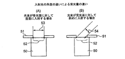
一般的なカメラに用いられるレンズには図5(A)に一例を示したように、シェーディングと呼ばれて撮像光学系における周辺部の光量が光軸の中心近傍より減少してしまう現象がある。この図5(A)において、横軸は結像面における光軸中心(0の位置)を通る直線上の位置、縦軸は光量、点線の「入力」として示した線は後記する色シェーディングが無いときのシェーディングによりレンズ周辺で光量が減少した入力光量値で、光軸中心画面位置に比較して周辺の光量が少なくなっているのがわかる。 As shown in an example in FIG. 5A, a lens used in a general camera has a phenomenon called “shading” in which the amount of light at the periphery of the imaging optical system decreases from the vicinity of the center of the optical axis. . In FIG. 5A, the horizontal axis is a position on a straight line passing through the optical axis center (position 0) on the imaging plane, the vertical axis is the amount of light, and the line shown as the dotted line “input” is color shading described later. It can be seen that the amount of light at the periphery is smaller than the screen position at the center of the optical axis, with the input light amount value where the amount of light has decreased around the lens due to shading when there is not.
このシェーディングは、撮影光学系の焦点距離や焦点位置、絞り値によって影響を受け、一般的に、望遠(長焦点)側より広角(短焦点)側の方が、焦点位置が遠距離側より近距離側の方が程度が大きくなる。また、絞りの径が小さい場合より開放絞り側の方が周辺における光量減少率は大きくなり、一般的なカメラでは、このシェーディングを極力抑えるような光学設計がなされている。 This shading is affected by the focal length, focal position, and aperture value of the photographic optical system. In general, the focal position is closer to the wide angle (short focus) side than the far distance side to the telephoto (long focus) side. The distance side becomes larger. Further, the reduction rate of the amount of light at the periphery is larger on the open aperture side than when the aperture diameter is small, and a general camera is optically designed to suppress this shading as much as possible.
他方、撮像素子上に光学レンズ系によって被写体像を結像させ、画像データとして取り出すようにしたデジタルカメラやビデオカメラ、または携帯電話などのカメラにおいては、撮像レンズにより撮像素子へ入射する光の角度により、撮像素子が受光できる光量に大きな影響を与える。例えば図6に示したように、50を撮像素子の1画素に相当するフォトダイオード部、51を撮像素子の遮光部、52を遮光部に開けた開口部、53をフォトダイオード50に垂直に入射する光の径、54を同じく斜めに入射したときの光の径とすると、個々の撮像素子の受光面に対して垂直に光が入射する場合は図6(A)に53で示したように効率良く光束を受けることができるが、図6(B)に示したように、入射光が垂直から傾くほど54で示したように光束が細くなって損失が増え、受光量が少なくなる。
On the other hand, in a camera such as a digital camera, a video camera, or a mobile phone in which a subject image is formed on an image pickup device by an optical lens system and taken out as image data, the angle of light incident on the image pickup device by the image pickup lens This greatly affects the amount of light that can be received by the image sensor. For example, as shown in FIG. 6, 50 is a photodiode portion corresponding to one pixel of the image sensor, 51 is a light shield portion of the image sensor, 52 is an opening formed in the light shield portion, and 53 is perpendicularly incident on the
そのため、デジタルカメラやビデオカメラ、または携帯電話などのカメラのように撮像素子を用いるカメラにおいて、こういった光学系や撮像素子に起因すると共に色シェーディングが無いときのシェーディングに対しては、例えば図5(B)に示したように、結像面における光軸中心位置を1とし、その光軸中心位置からの距離に応じた補正係数、または予め光量減少程度を測定することによって求めた補正係数を定め、光軸中心からの距離に対応させて入射光量に乗じてやることで、図5(A)に実線で「出力」として示したように、周辺部においても光量を略フラットな状態にすることができる。 Therefore, in a camera using an image sensor such as a digital camera, a video camera, or a camera such as a mobile phone, shading when there is no color shading due to such an optical system or image sensor is shown in FIG. As shown in FIG. 5 (B), the optical axis center position on the imaging plane is set to 1, and the correction coefficient corresponding to the distance from the optical axis center position, or the correction coefficient obtained by measuring the light amount reduction degree in advance. By multiplying the incident light amount in correspondence with the distance from the center of the optical axis, the light amount is made substantially flat even in the peripheral portion as shown as “output” by a solid line in FIG. can do.
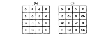
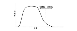
また、撮像素子(光電変換手段)はカラー画像を撮影できるようにするため、一例を図7(A)に示したようなベイヤ配列と呼ばれるモザイク状のカラーフィルタを用い、入射した光を各画素単位でR(赤)、G(緑)、B(青)に振り分けて色毎に分離した撮像データを得るために用いるが、撮像素子におけるフォトダイオードには、図8に示したように光の波長によって内部への光の到達距離が異なるという特性があり、そのため色によって同じ光量が入射しても、光の入射角度が垂直から大きく傾く周辺部では、中心部に比較して光量が少なくなるという現象も生じる。なお、ベイヤ配列は、図7(A)に示した3種類の色別だけでなく、図7(B)に示したように、更に細分化してR(赤)画素の列にあるGr画素、、B(青)画素の列にあるGb画素という様に、同じG(緑)でも並びの違いで種類分けが必要な場合もある。 In addition, in order to allow the image sensor (photoelectric conversion means) to capture a color image, a mosaic color filter called a Bayer array as shown in FIG. 7A is used as an example, and incident light is converted into each pixel. It is used to obtain imaging data that is divided into R (red), G (green), and B (blue) in units and separated for each color. The photodiode in the imaging device has a light as shown in FIG. There is a characteristic that the arrival distance of light to the inside differs depending on the wavelength, so even if the same amount of light enters depending on the color, the amount of light is less in the peripheral part where the incident angle of light is greatly inclined from the vertical compared to the center part This also occurs. Note that the Bayer arrangement is not limited to the three types of colors shown in FIG. 7A, but is further subdivided into Gr pixels in a row of R (red) pixels, as shown in FIG. , B (blue) pixels, such as Gb pixels in the column, there are cases where the same G (green) may need to be classified due to the difference in arrangement.
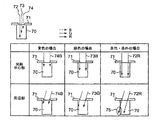
図8において70は撮像素子の1画素に相当するフォトダイオード部、71は遮光部、72の実線は赤(R)色の光のフォトダイオード部70への入射光束、73の点線は緑(G)色の光のフォトダイオード部70への入射光束、74の破線は青(B)色の光のフォトダイオード部70への入射光束を示しており、表における上段はフォトダイオード部70に垂直に入射する光束を、下段は周辺部でフォトダイオード70への光の入射角度が垂直から大きく傾いた場合のそれぞれの色の光束を表している。
In FIG. 8, 70 is a photodiode portion corresponding to one pixel of the image sensor, 71 is a light-shielding portion, 72 is a solid line of red (R) light incident on the
このうち、青(B)色74と緑(G)色73のように、赤(R)色72に対して波長が短い光は、フォトダイオード70における深部まで侵入することがないため、表の下段に示したように例え光の入射角度が垂直から大きく傾いても光量に大きな変化は生じない。それに対し赤(R)色72の波長の長い光は、フォトダイオード70における深部まで侵入するため光の入射角度が垂直から大きく傾くと、表の下段の右端の「赤色・赤外の場合」に75で示したように、光束の一部がフォトダイオード70の側壁を通過してしまって光量に寄与しない光が生じる。従って、本来あるべき光量よりR成分の光を少なめに検知してしまうこととなり、垂直に入射した場合を示した上段とは光量が異なってしまう。そのため、光の色(波長)の違いによってシェーディング特性に差が生じるから、色成分の構成比率が変化し、画面内に色むらが生じてしまう。
Of these, light having a shorter wavelength than the red (R)
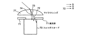
さらに、撮像素子を構成するフォトダイオード70は、図9に示したように入射してくる光を効率良く捉えるためにマイクロレンズ77を備えているが、このマイクロレンズ77による屈折角度は光の波長、すなわち色によって異なっている。そのため、フォトダイオード70に斜めに光が入射した場合、赤(R)色72、緑(G)色73、青(B)色74で示したように色によって入射角に違いが生じ、フォトダイオード70に達する光量が異なることになり、これによってもシェーディング特性に違いが生じる。
Further, the
また、色温度を検知するホワイトバランス制御において、画像周辺部のデータを用いた場合、この実際より赤(R)成分が少ない誤ったデータも加味されてホワイトバランス処理が行われる結果、本来正常なはずの中心部の赤(R)成分のデータまで修正が行われ、画面中心部が赤みを帯びて色むらが発生してしまう。 Further, in the white balance control for detecting the color temperature, when the data at the peripheral portion of the image is used, the white balance processing is performed by taking into account the erroneous data having a smaller red (R) component than the actual result, and as a result, it is normally normal. Correction is made to the red (R) component data that should be in the center, and the center of the screen is reddish and color unevenness occurs.
また、撮像装置に用いる一般的なCCD(Charge Coupled Device)やCMOS(Complementary Metal Oxide Semiconducter)を用いた撮像素子は、人間には見えない赤外線領域まで感度があるため、そのままでは得られる画像が人間に見えるものとは異なった色調となる。それを防止するため、一般的に赤外(IR)カットフィルタを用いて赤外線を遮断することが行われている。 In addition, an image pickup device using a general charge coupled device (CCD) or a complementary metal oxide semiconductor (CMOS) used in an image pickup apparatus has sensitivity to an infrared region that cannot be seen by humans. The color will be different from what you see. In order to prevent this, infrared rays are generally blocked using an infrared (IR) cut filter.
このIRカットフィルタには吸収タイプや反射(蒸着)タイプなどがあり、それぞれ異なった特性を有するが、光学系の条件の違いによって、このうち吸収型は光透過特性が変化することで色むらが発生し易く、反射型は光の入射する角度によってカットオフ周波数の特性が変化することで色むらが発生する。このように、それぞれのタイプや素材などによって赤外光のカット特性がまちまちであるため、レンズやセンサの構成に合ったIRカットフィルタを選択する必要がある。 This IR cut filter has an absorption type and a reflection (evaporation) type, and each has different characteristics. However, due to the difference in the conditions of the optical system, the absorption type has a color unevenness due to a change in light transmission characteristics. It is easy to occur, and the reflective type causes color unevenness due to the change in the characteristics of the cut-off frequency depending on the incident angle of light. As described above, since the cut characteristics of infrared light vary depending on the type and material, it is necessary to select an IR cut filter suitable for the lens and sensor configuration.
さらにIRカットフィルタには、図10に示したように完全に赤外線をカットできないものもあり、前記したように撮像装置の小型化・薄型化が進められる中で、画面周辺方向におけるIRカットフィルタや撮像素子への光の入射角度が垂直からより傾いていく傾向にあるため、画像の中心部と周辺部とで画像の赤みが異なって、自然な色調の画像を撮影することが難しい場合があり、このような問題が生じないIRカットフィルタを使用するとコストアップにつながることが多い。 Furthermore, some IR cut filters cannot cut infrared rays completely as shown in FIG. 10. As described above, as the image pickup apparatus is being reduced in size and thickness, the IR cut filter in the peripheral direction of the screen is used. Since the incident angle of light on the image sensor tends to be more inclined from the vertical, it may be difficult to capture natural-tone images due to the redness of the image at the center and the periphery of the image. If an IR cut filter that does not cause such a problem is used, the cost is often increased.
このような問題点を解決するため従来では、撮像素子に対する入射光が極力垂直に入射するよう像側テレセントリックな光学系が良いとされてきたが、この像側テレセントリックな光学系はある程度の光路長を必要とするため小型化・薄型化が難しく、小型化・薄型化をめざす場合は周辺部に入射する光の或る程度の入射角は受け入れざるを得ない。そこで、撮像素子における画面周辺部の画素に対応させて設けるマイクロレンズの形状を、傾きのある入射光を効率よく集光できる形状にした撮像素子等も提案されている。 Conventionally, in order to solve such problems, an image-side telecentric optical system has been considered good so that incident light to the image sensor is incident as vertically as possible. However, this image-side telecentric optical system has a certain optical path length. Therefore, it is difficult to reduce the size and thickness, and in order to reduce the size and thickness, a certain incident angle of light incident on the peripheral portion must be accepted. In view of this, there has been proposed an imaging device or the like in which the shape of a microlens provided in correspondence with the pixels on the periphery of the screen in the imaging device is a shape that can efficiently collect inclined incident light.
しかし、このようにマイクロレンズの形状を変えたものは、特定の傾きで入射する光に対しては有効であっても異なる傾きをもった入射光には対応できないから、ズームレンズのように光学系の焦点距離が変化することで撮像素子周辺に対する入射角が変化するものでは効果が得られなくなってしまう。 However, such a modified microlens shape is effective for incident light with a specific inclination, but cannot respond to incident light with a different inclination. If the angle of incidence with respect to the periphery of the image sensor changes as the focal length of the system changes, the effect cannot be obtained.
しかも、撮像装置は様々な分野・製品への組み込みが行なわれ、特に携帯電話等のモバイル機器への搭載にあたっては撮像装置の小型化・薄型化が求められる結果、必然的に光学系も小型化・薄型化し、撮像素子に入射する光の角度は周辺ほど垂直から大きく傾く事になって光軸の中心近傍と周辺との光量差がより大きくなる傾向にあり、対策の必要性が高くなっている。 In addition, image pickup devices are incorporated into various fields and products, and especially when mounted on mobile devices such as mobile phones, it is necessary to reduce the size and thickness of image pickup devices.・ Thinning, the angle of light incident on the image sensor tends to be greatly inclined from the vertical as it goes to the periphery, and the difference in the amount of light between the vicinity of the center of the optical axis and the periphery tends to become larger, and the need for countermeasures becomes higher Yes.
そのため本願出願人は、現在は非公知である特許文献1において、光学レンズに起因するシェーディングや撮像素子の特性に起因するシェーディング、及びIRカットフィルタに起因するシェーディングなど、複数存在するシェーディング要因でトータルなシェーディング特性が複合的な曲線となり、さらに、レンズの焦点位置や焦点距離、及び絞り値や色温度によって変化していくシェーディングを、適切に補正できるようにした撮像装置を提案した。
For this reason, the applicant of the present application in
それを簡単に説明すると、撮像光学系によって結像された被写体像を電気信号に変換するイメージセンサと、撮像光学系とイメージセンサとの間に設けられた赤外カットフィルタと、イメージセンサによって得られた画像データに対して演算処理を施すDSP(Digital Signal Processor)とを備えた撮像装置において、イメージセンサとDSPはそれぞれシェーディング補正機能を持ち、かつ、撮像光学系における焦点距離及び焦点位置の違いと絞り値との組み合わせと、撮像光学系における焦点距離及び焦点位置の違いと被写体の色温度の違いとの組み合わせとにより、シェーディング補正データをマトリックス状として配したシェーディング補正テーブルを作成し、光学系データ値と色温度とによって最適な組み合わせをこのシェーディング補正テーブルから選択できるようにすると共に、前記イメージセンサとDSPに設けた一のシェーディング補正機能で撮像光学系によって生じるシェーディングの補正を、他のシェーディング補正機能でイメージセンサおよび前記赤外カットフィルタによって生じるシェーディングの補正を行なうようにしたものである。 Briefly, it is obtained by an image sensor that converts an object image formed by the imaging optical system into an electrical signal, an infrared cut filter provided between the imaging optical system and the image sensor, and the image sensor. In an imaging apparatus having a DSP (Digital Signal Processor) that performs arithmetic processing on the obtained image data, the image sensor and the DSP each have a shading correction function, and a difference in focal length and focal position in the imaging optical system A shading correction table in which shading correction data is arranged in a matrix is created by combining the combination of the aperture value and the aperture value, and the combination of the difference in focal length and position in the imaging optical system and the difference in color temperature of the subject. Optimum combination by data value and color temperature The shading correction table can be selected from the shading correction table, and the shading correction generated by the image pickup optical system with one shading correction function provided in the image sensor and the DSP is corrected. The shading correction caused by the outer cut filter is corrected.
しかしながら、このようにして光学レンズに起因するシェーディングや撮像素子の特性に起因するシェーディング、及びIRカットフィルタに起因するシェーディングなど、複数存在するシェーディング要因でトータルなシェーディング特性が複合的な曲線となり、さらに、レンズの焦点位置や焦点距離、及び絞り値や色温度によって変化していくシェーディングを補正したにもかかわらず、なお、予期しない色シェーディングが発生することが判明した。 However, in this way, the total shading characteristics become a complex curve due to a plurality of shading factors, such as shading due to optical lenses, shading due to characteristics of the image sensor, and shading due to IR cut filters, and It has been found that despite the correction of shading that varies depending on the focal position and focal length of the lens, the aperture value, and the color temperature, unexpected color shading still occurs.
すなわち前記したデジタルカメラやビデオカメラ、または携帯電話などのカメラに用いられるCCDやCMOS等の撮像素子は、撮像した画像の高精細化を求めて画素数が飛躍的に増大している。一方、こういったデジタルカメラやビデオカメラ、または携帯電話などのカメラは小型化・薄型化が更に進み、撮像素子の周辺に入力する光線の焦点面に対する角度が更に大きくなる傾向にある。 That is, an image sensor such as a CCD or a CMOS used in the above-described digital camera, video camera, or camera such as a mobile phone has drastically increased the number of pixels in order to increase the definition of the captured image. On the other hand, such cameras such as digital cameras, video cameras, and mobile phones have been further reduced in size and thickness, and the angle of light rays input to the periphery of the image sensor tends to be larger.
そして前記した予期しない色シェーディングは、このように小型化・薄型化により、撮像素子の周辺に入力する光線の焦点面に対する角度が更に大きくなったことが一因となっている。これは、図11(A)に示したように、各撮像素子に入射する光の角度が大きくなることで、ベイヤ配列した別の色に対応した画素にまで光が入り込み、クロストークが発生することによる。 The unexpected color shading described above is partly due to the fact that the angle with respect to the focal plane of the light beam input to the periphery of the image sensor is further increased due to the reduction in size and thickness. As shown in FIG. 11A, as the angle of light incident on each image sensor increases, light enters a pixel corresponding to another color arranged in a Bayer array, and crosstalk occurs. It depends.
この図11において、80は前記した細分化したベイヤ配列であり、それぞれ対応するカラーフィルタを備えたGb画素、B画素、R画素、Gr画素が、例えばアルミ遮光膜81の中に納められて画素単位となり、この画素単位が多数配列されて撮像素子を形成している。82は光軸中心方向、83、84はクロストークを示す矢印で、図11(B)に示したように、光軸中心82からの入射光85が遮光部86から入ったとき、その入射角が大きいと、それぞれの画素の境界を越え、例えば図上最も左のGr画素(この図11(A)に示した画素単位の隣の画素単位になる)に入射した光は間にアルミ遮光膜81が有るため隣のR画素に入り込む光は少ないが、R画素に入射した光が隣のGr画素にも入射し、クロストークが生じることを示している。
In FIG. 11,
このクロストークは、光軸中心82から外周方向に向かって生じるから、図11(C)に示したように、画面右側はB画素とGr画素の影響が、画面左側は側はGb画素とR画素の影響が大きく出ることになり、前記した光学レンズに起因するシェーディングや撮像素子の特性に起因するシェーディング、及びIRカットフィルタに起因するシェーディングなどとは異なったシェーディングになる。
Since this crosstalk occurs from the
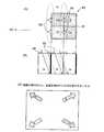
また他の要因として、撮像素子の画素数が飛躍的に増大したことで、例えばCMOSにおける電荷検出部(FD:Floating Diffusion)91を2画素に1つ、または図12(A)に示したように4画素に1つと複数の画素で共有することが行われている。この図12において、90は前記した細分化したベイヤ配列、91は各ベイヤ配列毎、すなわち4画素毎に設けられた電荷検出部(FD)、92は各画素毎の光の入射する開口である。 Another factor is that the number of pixels of the image sensor has increased dramatically. For example, a charge detection unit (FD: Floating Diffusion) 91 in CMOS is one in two pixels, or as shown in FIG. In addition, one in four pixels and a plurality of pixels are shared. In FIG. 12, 90 is the subdivided Bayer array, 91 is the charge detector (FD) provided for each Bayer array, that is, every four pixels, and 92 is an aperture through which light enters each pixel. .
そしてこの場合、各画素の開口部92が画素の境界部分に配置されることとなり、開口部92とマイクロレンズの光軸との位置関係が、図12(B)のように色フィルタ毎に異なってしまう(ミスマッチ)結果になる。そのため、同じ傾きを持った入射光に対し、色フィルタの種類によって入射光量に差が生じてしまい、カラーフィルタの配列の構造上、画面の右と左、上と下とでそれぞれ特性が逆転することになって、これらの要因により、色シェーディングは左右、上下で非対称な形状の特性を持つことになる。
In this case, the
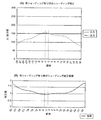
そのためこの場合のシェーディングは、図13(A)に点線で示したように同心円状の特性とならず、前記図5に示した場合のように、画面中心からの距離を変数とした式による補正ができない。なお、この図13において横軸は前記図5の場合と同様、結像面における光軸中心(0の位置)を通る直線上の位置、縦軸は光量で、点線で示した「入力」は補正前の入力光量値、実線で示した「出力」は補正後の光量値であり、また図13(B)は、この(A)に示したシェーディングを補正するための補正係数で、図13(A)に点線で示した入射光量にこの図13(B)の補正係数を乗じてやることで、図13(A)に実線で「出力」として示したように光量が略フラットとなる状態にすることができる。 Therefore, the shading in this case does not have a concentric characteristic as shown by a dotted line in FIG. 13A, but is corrected by an expression using the distance from the screen center as a variable as shown in FIG. I can't. In FIG. 13, the horizontal axis is the position on the straight line passing through the optical axis center (position 0) on the imaging plane, the vertical axis is the amount of light, and the “input” indicated by the dotted line is the same as in FIG. The input light amount value before correction, “output” indicated by a solid line is the light amount value after correction, and FIG. 13B is a correction coefficient for correcting the shading shown in FIG. By multiplying the incident light amount indicated by the dotted line in (A) by the correction coefficient of FIG. 13B, the light amount becomes substantially flat as indicated by “output” by the solid line in FIG. 13A. Can be.
ところがこの図13(A)のように、同心円状の特性とならないシェーディングにおいては、前記したクロストークや、マイクロレンズ位置のミスマッチにより、Gb画素、B画素、R画素、Gr画素の各色の違いにより、例えば図13(A)の画角−3度の位置の入力値のように、画面中心、すなわち0度における入力値より出力値が高くなってしまう現象が発生する場合がある。この場合、予め出力値が最大となる位置が分かっているわけではないので、前記と同様画面中心の定点(0度の位置)を例えば基準補正係数=1として補正係数を算出すると、画面中心より出力が大きい値となるこの−3度の位置の補正係数は、図13(B)における−3度の位置に示したように1未満となってしまう。 However, as shown in FIG. 13A, in shading that does not have a concentric characteristic, due to the crosstalk and the mismatch of the microlens position, due to differences in colors of the Gb pixel, B pixel, R pixel, and Gr pixel. For example, there may occur a phenomenon in which the output value becomes higher than the input value at the center of the screen, that is, 0 degree, like the input value at the position of the angle of view of −3 degrees in FIG. In this case, since the position where the output value is maximum is not known in advance, if the correction coefficient is calculated with the fixed point (0 degree position) at the center of the screen as the reference correction coefficient = 1, for example, as described above, the correction coefficient is calculated from the center of the screen. The correction coefficient at the position of -3 degrees at which the output becomes a large value is less than 1 as shown at the position of -3 degrees in FIG.
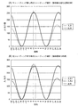
従って、例えば図14に示したように、横軸に画角、縦軸に入/出力値を取り、簡単化のため撮像素子からの画像データに対する補正後の出力データが図のようにサインカーブであるとした場合、例えば入/出力値256を色の飽和値とすると、点線で示した「入力」値における画角−3度の値がこの飽和値256であると、色シェーディングがない場合は前記図5(B)に示した補正係数を乗じてやることでこの図14(A)に実線で示した「出力」値のようになって特に問題はない。しかし、色シェーディングがある場合は、図14(B)の入力1のように、センサの飽和値より大きな値が本来の画像にあると、図13(B)のような1より小さな補正係数を掛け合わせることにより、図14(A)の出力のようになるべきところが、図14(B)における入力1が飽和値を越えているため、実際は、入力2のような値しか入力されてこなくなる。そのため、この図14(B)に実線で示した出力値のように、画角−3度では出力値が飽和値のままでなければいけないところがそれ以下となってしまい、本来色ムラを補正するはずの処理で、逆に色バランスを崩して色ムラを生じさせてしまう事になる。
Therefore, for example, as shown in FIG. 14, the angle of view is taken on the horizontal axis and the input / output value is taken on the vertical axis, and the output data after correction for the image data from the image sensor is a sine curve as shown in FIG. For example, if the input / output value 256 is a color saturation value, and the value of the angle of view −3 degrees in the “input” value indicated by the dotted line is the saturation value 256, there is no color shading. By multiplying the correction coefficient shown in FIG. 5B, there is no particular problem as the “output” value shown by the solid line in FIG. 14A is obtained. However, when there is color shading, if the original image has a value larger than the saturation value of the sensor as in
色シェーディングの補正については、例えば特許文献2に、画像のシェーディング補正を高速に行うため、撮像素子により撮像された画像のシェーディング補正をベイヤーデータの段階で行ない、各画素Pについて光軸に相当するベイヤー画像の補正中心Oとの間の水平距離Hと垂直距離Vとを取得し、それらを二次関数に当てはめることにより、各画素Pにおける補正中心Oとの距離Lに応じたシェーディング係数を算出し、算出した画素毎のシェーディング係数に応じて各画素の明るさを調整するようにした撮像装置が示されている。
As for color shading correction, for example, in
しかしながらこの特許文献2に示された方法では、色シェーディングの補正を行うため、各画素Pについて光軸に相当するベイヤー画像の補正中心Oとの間の水平距離Hと垂直距離Vとを取得し、それらを二次関数に当てはめ、各画素Pにおける補正中心Oとの距離Lに応じたシェーディング係数を算出しているが、前記したように図13(A)のように同心円状の特性とならないシェーディングでは、その特性は性質の特定が困難であり、このように二次関数で算出するなどのことはできない。
However, in the method disclosed in
そのため本発明においては、ベイヤ配列した別の色の画素に光が入り込むことで生じるクロストークや、画素とマイクロレンズの光軸との位置関係が色フィルタ毎に異なってしまうミスマッチ等が原因で生じ、同心円状の特性とならない(非同心円状)色シェーディングを、色バランスを崩すようなことなく正確に補正することができる、撮像装置におけるシェーディング補正方法と装置を提供することが課題である。 For this reason, in the present invention, it is caused by crosstalk caused by light entering pixels of another color arranged in a Bayer array, a mismatch in which the positional relationship between the pixels and the optical axis of the microlens differs for each color filter, or the like. An object of the present invention is to provide a shading correction method and apparatus in an imaging apparatus that can accurately correct color shading that does not have concentric characteristics (non-concentric) without losing color balance.
上記課題を解決するため本発明になる撮像装置におけるシェーディング補正方法は、
撮像光学系と、撮像素子を有する光電変換部と、制御部を有する信号処理部とを有し、前記光電変換部と前記信号処理部の少なくとも一方にシェーディング補正の演算手段を備え、前記撮像光学系によって前記撮像素子上に結像された画像データに対し、前記撮像光学系と撮像素子に起因するシェーディングを前記演算手段によって補正係数を乗じて補正する、撮像装置におけるシェーディング補正方法であって、
前記シェーディングはその特性が非同心円状であり、前記補正係数は、最も小さな補正係数が1となるような調整係数を前記演算手段によって乗じられて調整有り補正係数とされ、該調整有り補正係数を前記演算手段によって画像データに乗じてシェーディングを補正することを特徴とする。
In order to solve the above problems, a shading correction method in an imaging apparatus according to the present invention is as follows.
An imaging optical system; a photoelectric conversion unit including an image sensor; and a signal processing unit including a control unit, wherein at least one of the photoelectric conversion unit and the signal processing unit includes a shading correction calculation unit; A shading correction method in an imaging apparatus, wherein image data imaged on the imaging element by a system is corrected by multiplying a shading caused by the imaging optical system and the imaging element by a correction coefficient by the arithmetic means,
The shading has a non-concentric characteristic, and the correction coefficient is multiplied by an adjustment coefficient such that the smallest correction coefficient is 1 to be an adjustment coefficient with adjustment. The shading is corrected by multiplying the image data by the calculating means.
そして、このシェーディング補正方法を実施するシェーディング補正装置は、
撮像光学系と、撮像素子を有する光電変換部と、制御部を有する信号処理部とを備え、前記撮像光学系と撮像素子とに起因するシェーディングの補正係数を記憶し、前記撮像光学系によって前記撮像素子上に結像された画像データに対して前記補正係数を乗じて補正するシェーディング補正の演算手段を有する撮像装置におけるシェーディング補正装置において、
前記シェーディングはその特性が非同心円状であり、前記シェーディング補正手段は、前記補正係数のうち最も小さな補正係数を1とする調整係数を前記演算手段によって乗じて調整した調整有り補正係数を前記補正係数として記憶し、該調整有り補正係数を前記演算手段によって画像データに乗じてシェーディングを補正することを特徴とする。
And the shading correction apparatus which implements this shading correction method is
An imaging optical system, a photoelectric conversion unit having an imaging element, and a signal processing unit having a control unit, storing a correction coefficient of shading caused by the imaging optical system and the imaging element, and the imaging optical system In a shading correction apparatus in an imaging apparatus having a shading correction calculation unit that corrects the image data imaged on the imaging element by multiplying the correction coefficient,
The shading has a non-concentric characteristic, and the shading correction means adjusts a correction coefficient with adjustment obtained by multiplying the correction coefficient by 1 with the smallest correction coefficient among the correction coefficients by the calculation means. And the shading is corrected by multiplying the image data by the correction coefficient with adjustment.
このように特性が非同心円状のシェーディングを、補正係数のうち、最も小さな補正係数を1とする調整係数を補正係数に乗じて調整有り補正係数とし、該調整有り補正係数によって非同心円状のシェーディングを補正することで、ベイヤ配列した別の色の画素に光が入り込むことで生じるクロストークや、画素とマイクロレンズの光軸との位置関係が色フィルタ毎に異なってしまうミスマッチ等が原因で生じた色シェーディングも、前記したように補正係数が1以下になることによって本来飽和するはずの色が飽和せずに色バランスを崩すようなことがなくなり、正確に補正する撮像装置におけるシェーディング補正方法と装置を提供することができる。 In this way, the shading having a non-concentric characteristic is converted into a correction coefficient with adjustment by multiplying the correction coefficient by the adjustment coefficient with the smallest correction coefficient being 1 among the correction coefficients, and the non-concentric shading is determined by the correction coefficient with adjustment. This is caused by crosstalk caused by light entering pixels of another color arranged in a Bayer array, mismatches where the positional relationship between the pixels and the optical axis of the microlens differs for each color filter, etc. As described above, the shading correction method in the image pickup apparatus that corrects the color shading accurately does not cause a color balance that does not saturate because the correction coefficient becomes 1 or less as described above. An apparatus can be provided.
そして、前記調整有り補正係数は、前記撮像素子上に設定した複数の定点に対応させて前記制御部に記憶させておくことで、容易に上記したシェーディング補正を実施することができ、さらに、前記調整有り補正係数を用いてシェーディング補正を行なう際に、前記撮像装置の露光量の目標値を前記調整係数の逆数を乗じた値に置き換えて露光制御を行なうことで、単純に調整有り補正係数を乗じると、前記補正係数に調整係数を乗じることで補正係数は調整係数分大きくなり、画像データは露出オーバーとなるが、このように画像データに予め調整係数の逆数を乗じることで、そういったことを防止することもできる。 The adjustment coefficient with adjustment can be easily performed by performing the above-described shading correction by storing the adjustment coefficient in correspondence with a plurality of fixed points set on the image sensor in the control unit. When performing shading correction using the adjustment coefficient with adjustment, exposure control is performed by replacing the target value of the exposure amount of the imaging device with a value obtained by multiplying the reciprocal of the adjustment coefficient. By multiplying the correction coefficient by the adjustment coefficient, the correction coefficient increases by the adjustment coefficient, and the image data is overexposed.In this way, multiplying the image data by the inverse of the adjustment coefficient in advance It can also be prevented.
また、前記光電変換部と信号処理部の両方がシェーディング補正の演算手段を有する場合は、前記シェーディング補正は前記光電変換部と信号処理部のうち、色に関するシェーディング補正を司る方で実施することにより、例えば従来用いられていた、光電変換手段または制御部のいずれかに備わったシェーディング補正機能単独では、レンズの焦点位置や焦点距離、絞り値などの光学系自体に起因するシェーディング、撮像素子へ入射する光の角度に起因するシェーディング、波長の長い光における撮像素子内部への侵入深さに起因するシェーディング、IRカットフィルタを用いた場合にフィルタ自体の特性に起因するシェーディング、特性が非同心円状のシェーディングなど、要因が複数存在してこれらの特性の組み合わせにより複合曲線となるシェーディングの総てを補正することが困難であったが、光電変換手段と制御部のそれぞれにシェーディング補正機能を持たせ、色に関するシェーディング補正機能を司る方で実施することで、シェーディングを適切に補正できる撮像装置を提供することができる。 In addition, when both the photoelectric conversion unit and the signal processing unit have a shading correction calculation unit, the shading correction is performed by performing one of the photoelectric conversion unit and the signal processing unit that performs shading correction related to color. For example, with a conventional shading correction function alone provided in either the photoelectric conversion means or the control unit, shading caused by the optical system itself such as the focal position, focal length, and aperture value of the lens is incident on the image sensor. Shading caused by the angle of the light to be emitted, shading caused by the penetration depth of the light into the image sensor with long wavelength light, shading caused by the characteristics of the filter itself when an IR cut filter is used, and the characteristics are non-concentric Multiple factors, such as shading, are combined by combining these characteristics. Although it was difficult to correct all of the shading that becomes a line, the shading correction function is given to each of the photoelectric conversion means and the control unit, and the shading correction function related to the color is performed, so that shading is performed. An imaging apparatus capable of appropriately correcting can be provided.
本発明によれば、ベイヤ配列におけるクロストークやマイクロレンズの光軸がミスマッチすることで生じる同心円状の特性とならない色シェーディングを、色バランスを崩すようなことなく正確に補正することができ、撮像装置の色再現性を最大限引き出せるシェーディング補正方法と装置を提供することができる。 According to the present invention, it is possible to accurately correct color shading that does not have concentric characteristics caused by crosstalk in a Bayer array or mismatched optical axes of microlenses without losing color balance. It is possible to provide a shading correction method and apparatus that can maximize the color reproducibility of the apparatus.
以下、図面を参照して本発明の好適な実施例を例示的に詳しく説明する。但しこの実施例に記載されている構成部品の相対的配置等は、この発明の範囲をそれに限定する趣旨ではなく、単なる説明例に過ぎない。 Hereinafter, exemplary embodiments of the present invention will be described in detail with reference to the drawings. However, the relative arrangement of the components described in this embodiment is not intended to limit the scope of the present invention, but is merely an illustrative example.
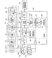
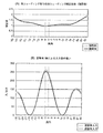
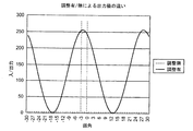
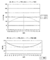
図1は本発明になる撮像装置における制御部分のブロック図、図2は前記した同心円状の特性とならない(非同心円状)シェーディングを補正する、本発明になるシェーディング補正方法を実施するために補正係数を持たせる定点を示した図、図3は同心円状の特性とならないシェーディングを補正する補正係数が1以下になる点を持つ場合、(A)は全ての点の補正係数が1以上となるよう調整することを説明するためのグラフで、(B)はそれによって露出オーバーにならないよう撮像素子からの画像データを調整した場合(調整有)と、(調整無)の場合を示したグラフ、図4は同心円状の特性とならないシェーディングを補正する補正係数が1以下になる点を持つ場合、全ての点の補正係数が1以上となるよう調整し、かつ、露出オーバーにならないよう撮像素子からの画像データに補正係数の逆数を予め乗じた場合(調整有)と、補正係数が1以下のまま撮像素子からの画像データに補正係数を乗じた場合(調整無)のグラフである。 FIG. 1 is a block diagram of a control portion in an imaging apparatus according to the present invention, and FIG. 2 is a correction for carrying out the shading correction method according to the present invention for correcting shading that does not have concentric characteristics (non-concentric). FIG. 3 shows a fixed point having a coefficient. FIG. 3 shows that when a correction coefficient for correcting shading that does not have concentric characteristics is 1 or less, (A) shows that the correction coefficient for all points is 1 or more. (B) is a graph showing a case where the image data from the image sensor is adjusted so as not to be overexposed (with adjustment) and a case where (without adjustment), FIG. 4 shows that when there is a point where the correction coefficient for correcting shading that does not have a concentric characteristic is 1 or less, adjustment is made so that the correction coefficient for all points is 1 or more, and the exposure value is adjusted. When the image data from the image sensor is multiplied in advance by the reciprocal of the correction coefficient so that it does not become a bar (with adjustment), and when the image data from the image sensor is multiplied by the correction coefficient while the correction coefficient is 1 or less (no adjustment) It is a graph of.
最初に図2乃至図4を用い、本発明になるシェーディング補正方法を簡単に説明する。まず図2は、前記した同心円状の特性とならないシェーディングを補正するため、補正係数を持たせる定点を示した図である。図中40は撮像画像を示し、41の小さな□で示したのが補正係数を持たせる定点である。
First, the shading correction method according to the present invention will be briefly described with reference to FIGS. First, FIG. 2 is a diagram showing a fixed point having a correction coefficient in order to correct shading that does not have the above-mentioned concentric characteristics. In the figure,
前記した図13(A)に示したように同心円状の特性とならない(非同心円状)シェーディングでは、その特性は性質の特定が困難であるため、補正係数は実測値に基づいて設定する必要がある。この場合、その補正係数を画素毎に持たせるのが理想であるが、そうするとデータ量が非常に大きくなってしまうため、例えばこの図2に示したように、画面上の格子状にした交点を定点として設定し、その定点毎に補正係数を持たせ、定点間については周辺の定点からの距離などに基づいて補正係数を導き出し、補間することで色シェーディングの補正を行なうようにする方法を取る。なお、この図2に示した定点の位置はあくまでも一例であり、この数、位置に限定されないことは明かである。 As shown in FIG. 13A, in the case of shading that does not have a concentric characteristic (non-concentric), it is difficult to specify the characteristic of the characteristic, so the correction coefficient must be set based on the actual measurement value. is there. In this case, it is ideal to provide the correction coefficient for each pixel. However, since the amount of data becomes very large in that case, for example, as shown in FIG. Set as fixed points, and have a correction coefficient for each fixed point. For the fixed points, a correction coefficient is derived based on the distance from surrounding fixed points, etc., and the color shading is corrected by interpolation. . It should be noted that the position of the fixed point shown in FIG. 2 is merely an example, and it is obvious that the position is not limited to this number and position.
この補正係数は、まずホワイトバランスを合わせた状態で、面光源などの均一な画像を撮影し、画面の定点毎における各画素の出力値を求める。そして、定点毎のベイヤ配列を形成する4つの画素の平均値と各画素の平均値に対する割合を算出し、定点の一つを基準点として、基準点とそれ以外の定点の画素について割合を掛け合わせ、補正係数とする。 As for the correction coefficient, a uniform image such as a surface light source is first taken with white balance adjusted, and an output value of each pixel at each fixed point on the screen is obtained. Then, the average value of the four pixels forming the Bayer array for each fixed point and the ratio to the average value of each pixel are calculated, and one of the fixed points is used as a reference point, and the ratio is multiplied for the reference point and the other fixed point pixels. Combined with the correction coefficient.
この図2において、例えば画面中心の画素41Cを基準定点とし、周辺の41Aの位置の定点の補正係数を算出する場合、画面中心の画素41Cの出力値をGr_C、R_C、B_C、Gb_Cとし、周辺の41Aの位置の定点の出力値をGr_0、R_0、B_0、Gb_0とする。前記した色シェーディングがある場合、各画素の出力バランスが崩れているため、画面中心41Cの平均値(Ave_C)と周辺41Aの平均値(Ave_0)をそれぞれ算出すると、下記(1)式のようになる。
(Ave_C)=(Gr_C+R_C+B_C+Gb_C)/4
(Ave_0)=(Gr_0+R_0+B_0+Gb_0)/4 ……(1)
In FIG. 2, for example, when the
(Ave_C) = (Gr_C + R_C + B_C + Gb_C) / 4
(Ave_0) = (Gr_0 + R_0 + B_0 + Gb_0) / 4 (1)
そのため、周辺41Aの位置における各画素のシェーディング補正係数Coef_Gr_0、Coef_R_0、Coef_B_0、Coef_Gb_0を算出すると、下記(2)式のようになる(なお、(1)式、(2)式はそれぞれ2つの式と4つの式を纏めて指すものとする)。
Coef_Gr_0=(Ave_0/Gr_0)*(Gr_C/Ave_C)
Coef_R_0 =(Ave_0/ R_0)*( R_C/Ave_C)
Coef_B_0 =(Ave_0/ B_0)*( B_C/Ave_C)
Coef_Gb_0=(Ave_0/Gb_0)*(Gb_C/Ave_C) ……(2)
Therefore, when the shading correction coefficients Coef_Gr_0, Coef_R_0, Coef_B_0, and Coef_Gb_0 of each pixel at the position of the
Coef_Gr_0 = (Ave_0 / Gr_0) * (Gr_C / Ave_C)
Coef_R_0 = (Ave_0 / R_0) * (R_C / Ave_C)
Coef_B_0 = (Ave_0 / B_0) * (B_C / Ave_C)
Coef_Gb_0 = (Ave_0 / Gb_0) * (Gb_C / Ave_C) (2)
このようにして算出した補正係数をプロットしたのが、図3(A)に点線で「調整前」として示した線である。この図3(A)は前記図13(B)と同様、横軸が撮像素子の結像面における光軸中心(0の位置)を通る直線上の位置、縦軸は補正係数(補正値)で、点線で示した「調整前」は上記(2)式で算出した補正係数である。 The correction coefficients calculated in this manner are plotted as a line indicated as “before adjustment” by a dotted line in FIG. In FIG. 3A, as in FIG. 13B, the horizontal axis is a position on a straight line passing through the optical axis center (position 0) on the imaging plane of the image sensor, and the vertical axis is a correction coefficient (correction value). “Before adjustment” indicated by a dotted line is the correction coefficient calculated by the above equation (2).
しかしこうして算出した係数は、前記図13(B)と同様、1未満となることがあるから、そのままでは使えない。そのため本発明においては、前記(2)式によって図2の全ての定点について算出した補正係数の中から最小値を抽出し、その値の逆数を調整係数として各定点の補正係数に乗じたものを各定点の新しい補正係数とすることにしたものである。このようにすることにより、図3(A)に実線で「調整後」として示したように、全ての補正係数が1以上となり、前記図14(B)に示したように飽和値がシェーディング補正によって飽和値でなくなり、本来色ムラを補正するはずの処理で、逆に色バランスを崩して色ムラを生じさせてしまう、といったことを防ぐことができる。 However, since the coefficient calculated in this way may be less than 1 as in FIG. 13B, it cannot be used as it is. Therefore, in the present invention, the minimum value is extracted from the correction coefficients calculated for all the fixed points in FIG. 2 by the above equation (2), and the correction coefficient of each fixed point is multiplied by the reciprocal of the value as the adjustment coefficient. The new correction coefficient for each fixed point is used. As a result, as shown in FIG. 3 (A) by the solid line as “after adjustment”, all the correction coefficients become 1 or more, and the saturation value becomes the shading correction as shown in FIG. 14 (B). Therefore, it is possible to prevent the color balance from being lost due to the processing that should be corrected for the color unevenness due to the loss of the saturation value.
しかしこのようにした場合、この値で色シェーディング補正を行なうと、全体のレベルが最小の補正係数の逆数、すなわち調整係数の割合でアップしてしまうことになり、それだけ露出オーバーになってしまう。そのため本発明においては、予め露光量の目標自体を前記抽出した最小の補正係数の割合(調整係数)分下げておくようにした。 However, in this case, if color shading correction is performed with this value, the overall level will be increased by the reciprocal of the minimum correction coefficient, that is, the ratio of the adjustment coefficient, resulting in overexposure. Therefore, in the present invention, the exposure target itself is lowered in advance by the ratio (adjustment coefficient) of the extracted minimum correction coefficient.
このようにして撮像素子からの入力値を調整した場合を示したのが図3(B)のグラフである。この図3(B)において横軸は画角、縦軸は入/出力値であり、前記図14の場合と同様簡単化のために撮像素子からの画像データをサインカーブであるとしてある。この図3(B)において点線の「調整無入力」は、露光量の目標を下げていない状態の撮像素子からの画像データであり、実線の「調整有入力」は予め露光量の目標値を最小の補正係数の割合分下げた状態の撮像素子からの画像データである。 The graph of FIG. 3B shows the case where the input value from the image sensor is adjusted in this way. In FIG. 3B, the horizontal axis represents the angle of view, and the vertical axis represents the input / output value. For the sake of simplification, the image data from the image sensor is assumed to be a sine curve. In FIG. 3B, the dotted “no adjustment input” is image data from the image sensor in a state where the exposure amount target is not lowered, and the solid “adjustment input” indicates the exposure amount target value in advance. This is image data from the image sensor in a state where it is lowered by the minimum correction coefficient ratio.
このように、露光量の目標値を最小の補正係数の割合分下げた状態の撮像素子からの画像データに前記図3(A)に「調整後」として示した補正係数を乗じてやることで、図4に「調整有」として示した実線のグラフのように、飽和値がシェーディング補正によっても飽和値のままとなり、色バランスを崩して色ムラを生じさせてしまう、といったことを防いだ撮像装置におけるシェーディング補正方法を提供することができる。 In this way, by multiplying the image data from the image sensor in which the target value of the exposure amount is reduced by the minimum correction coefficient ratio, the correction coefficient shown as “after adjustment” in FIG. As shown in the solid line graph shown as “adjusted” in FIG. 4, the saturation value remains the saturation value even after the shading correction, preventing the color balance from being lost and causing color unevenness. A shading correction method in the apparatus can be provided.
以下、図1を用い、本発明になるシェーディング補正方法を実施する撮像装置について説明する。図1において、10は撮像装置における光学系を構成するズームレンズ、11はオートフォーカス用レンズであり、この図1では簡単化のためにそれぞれ単レンズで示したが、一般的に用いられるズームレンズやオートフォーカス用レンズのように複数のレンズにより構成される。12は光学系の絞り、13はIR(赤外)カットフィルタ、14は、撮像素子15におけるアンプ雑音とリセット雑音を除去するCDS(Correlated Double Sampling)回路16、増幅率をコントロールするAGC(Automatic Gain Control)回路17、撮像素子からのアナログ信号をデジタル信号に変換するAD(Analog/Digital)変換回路18、そしてイメージセンサ側のシェーディング補正回路(1)19などが一体となった光電変換手段たるイメージセンサである。
Hereinafter, an imaging apparatus that implements the shading correction method according to the present invention will be described with reference to FIG. In FIG. 1,
20は、イメージセンサ14で得られた画像信号を処理する演算手段たるDSP(Digital Signal Processor)である。このDSP20の中には、イメージセンサ14で得られた画像信号を受けるセンサインターフェイス21、DSP20側でシェーディングの補正を行うシェーディング補正回路(2)22、シェーディング補正を行った画像信号を表示や記録が行なえる形に処理を施す信号処理部23、画像表示部・画像記録部33へ処理が済んだ画像信号を送り出す出力インターフェイス回路24が含まれる。また、信号処理部23からの信号によって露出値を取得する露出値取得回路26と、その露出値取得回路26が取得した露出値によって露出設定値を算出する露出設定値算出回路27と、この露出設定値算出回路27が算出した設定値を、前記した露光量の目標自体を前記抽出した最小の補正係数の割合分下げるため、前記(2)式によって図2の全ての定点について算出した補正係数の中から抽出した最小値の逆数を調整係数とし、その調整係数で除して結果をAGC回路17、駆動部インターフェイス(I/O)回路30に送り出す調整係数除算回路28と、同じく前記(2)式によって図2の全ての定点について算出した補正係数にこの調整係数を乗じてシェーディング補正回路(1)、シェーディング補正回路(2)に送る調整係数乗算回路29とで構成され、図示していないCPUを含む制御部25も含まれている。
またこの制御部25からは、調整係数除算回路28から送られる設定値を調整係数で除した値が駆動部インターフェイス(I/O)回路30に送られ、ズームレンズ10やオートフォーカス用レンズ11、絞り12等を動作させるモータ321、322、323を駆動する、モータドライバ311、312、313への信号となる。さらにこの駆動部インターフェイス(I/O)回路30は、逆にモータドライバ311、312、313からの信号を受け、ズームレンズ10やオートフォーカス用レンズ11における焦点距離、焦点位置、絞り12の状態を受け、図示していないCPUが、必要な情報をシェーディング補正回路(1)19、シェーディング補正回路(2)22に送る。
Further, the
次にこの図1を用い、本発明になる撮像装置の動作について説明する。図示していない電源が投入されると、ズームレンズ10、オートフォーカス用レンズ11、絞り12、IRカットフィルタ13を通してイメージセンサ14内の撮像素子15に結像して得られた画像データは、CDS回路16によって撮像素子15におけるアンプ雑音とリセット雑音が除去され、AGC回路17で適正な信号レベルに増幅されてAD変換回路18でアナログ/デジタル変換が行われる。また、シェーディング補正回路(1)19では後記するように制御部25からの指示によってシェーディング補正処理(1)がなされ、DSP20に送り込まれる。
Next, the operation of the imaging apparatus according to the present invention will be described with reference to FIG. When a power supply (not shown) is turned on, the image data obtained by forming an image on the
DSP20内では、センサインターフェイス21を介して送り込まれた画像信号が、シェーディング補正回路(2)22で、後記するように制御部25の指示に従うシェーディング補正処理(2)がなされ、信号処理部23でさらにカラー調整、ガンマ補正、輝度信号生成等の演算が施される。そして、出力インターフェイス回路24から画像表示部・画像記録部32に送られて画像表示や外部記憶装置などへの記録が行われる。
In the
また、制御部25では、信号処理部23で処理された画像データから露出値取得回路26によって露出値が取得され、その取得した露出値によって露出設定値算出回路27が露出設定値を算出する。そしてこの露出設定値算出回路27が算出した設定値は、調整係数除算回路28により、前記した露光量の目標自体を前記抽出した最小の補正係数の割合分下げるため、前記(2)式によって図2の全ての定点について算出した補正係数の中から抽出した最小値の逆数を調整係数として、その調整係数によって除される。そして結果がAGC回路17、駆動部インターフェイス(I/O)回路30に送り出される。
In the
AGC回路17はこの送られてきた結果を受け、CDS回路16によって撮像素子15におけるアンプ雑音とリセット雑音が除去されて送られてきた画像データの信号レベルを、前記図3(B)に「調整有入力」として示したように調整してAD変換回路18に送る。
The
一方、この制御部25を構成する調整係数乗算回路29では、前記図3(A)に点線で「調整前」として記した補正係数に上記した調整係数を乗じ、結果をシェーディング補正回路(1)、シェーディング補正回路(2)に送る。
On the other hand, the adjustment
また制御部25は、図示していないCPUにより駆動部インターフェイス(I/O)30を介し、レンズ駆動や絞りを制御すると共に、その時点のズームレンズ10とオートフォーカス用レンズ11の焦点位置、焦点距離等のレンズ状態、及び絞り12などの光学系データ値を、それぞれを駆動するモータ311、312、313のモータドライバ301、302、303から駆動部インターフェイス30を介して受け、例えばシェーディング補正回路(1)19に送る。
In addition, the
そしてシェーディング補正回路(1)19は、送られてきた現在のレンズ状態と絞り径に対応させ、AD変換回路18を介して送られてくる画像データ中の各画素における出力値に対し、前記調整係数乗算回路29で算出された調整済み補正係数を乗じ、現在のレンズ状態と絞り径に対応したシェーディング補正を実施する。
Then, the shading correction circuit (1) 19 makes the adjustment to the output value at each pixel in the image data sent via the
またシェーディング補正回路(2)22は、例えば制御部25により検出された色温度の情報や、先に取得したズームレンズ10とオートフォーカス用レンズ11の焦点位置、焦点距離等のレンズ状態、及び絞り12などを参照しながら、センサインターフェイス21を介して送られてくる画像データ中の各画素に対し、前記調整係数乗算回路29で算出された調整済み補正係数を乗じ、現在の色温度に応じたシェーディング補正を実施する。
In addition, the shading correction circuit (2) 22 includes, for example, information on the color temperature detected by the
このように、イメージセンサ14側とDSP20側の両方で別個にシェーディング補正を行うのは、一般的にイメージセンサ14側のシェーディング補正機能は自由度が少なく、複雑なシェーディング補正をすることが難しいのに対し、DSP20側のシェーディング補正機能は自由度が大きく、前記したような複合曲線に対しても対応可能であるからであり、このようにシェーディングが発生する要因によってシェーディングを補正する手段を分けることで、確実にシェーディング補正できる撮像装置を提供することができる。なお、光学レンズに起因して生じる画像の中心部と周辺部との明るさが異なる現象や、撮像素子や赤外(IR)カットフィルタの特性に起因して生じる画像の中心部と周辺部とにおける明るさや色に対する感度の違い、などによるシェーディングの補正については、前記特許文献1に詳述されているので省略する。
As described above, the shading correction performed separately on both the
このようにしてシェーディング補正を行うことにより、前記したようにベイヤ配列した別の色の画素に光が入り込むことで生じるクロストークや、画素とマイクロレンズの光軸との位置関係が色フィルタ毎に異なってしまうミスマッチ等が原因で生じ、同心円状の特性とならない色シェーディングを、飽和値をシェーディング補正によっても飽和値のままとして、かつ、露光オーバーをも補正して、色バランスを崩して色ムラを生じさせてしまう、といったことを防いだシェーディング補正方法を実施する撮像装置を提供することができる。 By performing shading correction in this manner, crosstalk caused by light entering into another color pixel arranged as described above, and the positional relationship between the pixel and the optical axis of the microlens are different for each color filter. Color shading that does not have concentric characteristics due to mismatch or the like that differs, leaves the saturation value to the saturation value even by shading correction, and corrects overexposure to break up the color balance and color unevenness. It is possible to provide an imaging apparatus that implements a shading correction method that prevents the occurrence of the above.
なお、以上の説明では、絞り値を含むレンズ状態によるシェーディングの補正をシェーディング補正回路(1)19で、色温度によるシェーディングの補正をシェーディング補正回路(2)22で行うよう説明したが、これは逆であっても構わない。 In the above description, the shading correction according to the lens state including the aperture value is corrected by the shading correction circuit (1) 19, and the shading correction by the color temperature is corrected by the shading correction circuit (2) 22. The reverse is also acceptable.
本発明によれば、クロストークや撮像素子における画素とマイクロレンズの光軸とのミスマッチ等が原因で生じ、同心円状の特性とならない色シェーディングを、色バランスを崩すようなことなく正確に補正することができるから、小型化、薄型化したデジタルカメラ、または携帯電話などのカメラなどに用いて好適な撮像装置とシェーディング補正方法を提供することができる。 According to the present invention, color shading that does not have concentric characteristics due to crosstalk or a mismatch between a pixel in the image sensor and the optical axis of the microlens is corrected accurately without losing color balance. Therefore, it is possible to provide an imaging device and a shading correction method that are suitable for use in a downsized and thin digital camera or a camera such as a mobile phone.
10 ズームレンズ
11 オートフォーカス用レンズ
12 絞り
13 IR(赤外)カットフィルタ
14 イメージセンサ
15 撮像素子
16 CDS回路
17 AGC回路
18 AD変換回路
19 イメージセンサ側のシェーディング補正回路(1)
20 DSP(Digital Signal Processor)
21 センサインターフェイス
22 シェーディング補正回路(2)
23 信号処理部
24 出力インターフェイス回路
25 制御部
26 露出値取得回路
27 露出設定値算出回路
28 調整係数除算回路
29 調整係数乗算回路
30 駆動部インターフェイス(I/O)回路
311、312、313 モータドライバ
321、322、323 モータ
33 画像表示部・画像記録部
DESCRIPTION OF
20 DSP (Digital Signal Processor)
21
23
Claims (5)
前記シェーディングはその特性が非同心円状であり、前記補正係数は、最も小さな補正係数が1となるような調整係数を前記演算手段によって乗じられて調整有り補正係数とされ、該調整有り補正係数を前記演算手段によって画像データに乗じてシェーディングを補正することを特徴とする撮像装置におけるシェーディング補正方法。 An imaging optical system; a photoelectric conversion unit including an image sensor; and a signal processing unit including a control unit, wherein at least one of the photoelectric conversion unit and the signal processing unit includes a shading correction calculation unit; A shading correction method in an imaging apparatus, wherein image data imaged on the imaging element by a system is corrected by multiplying a shading caused by the imaging optical system and the imaging element by a correction coefficient by the arithmetic means,
The shading has a non-concentric characteristic, and the correction coefficient is multiplied by an adjustment coefficient such that the smallest correction coefficient is 1 to be an adjustment coefficient with adjustment. A shading correction method in an imaging apparatus, wherein the shading is corrected by multiplying image data by the arithmetic means.
前記シェーディングはその特性が非同心円状であり、前記シェーディング補正手段は、前記補正係数のうち最も小さな補正係数を1とする調整係数を前記演算手段によって乗じて調整した調整有り補正係数を前記補正係数として記憶し、該調整有り補正係数を前記演算手段によって画像データに乗じてシェーディングを補正することを特徴とする撮像装置におけるシェーディング補正装置。 An imaging optical system, a photoelectric conversion unit having an imaging element, and a signal processing unit having a control unit, storing a correction coefficient of shading caused by the imaging optical system and the imaging element, and the imaging optical system In a shading correction apparatus in an imaging apparatus having a shading correction calculation unit that corrects the image data imaged on the imaging element by multiplying the correction coefficient,
The shading has a non-concentric characteristic, and the shading correction means adjusts a correction coefficient with adjustment obtained by multiplying the correction coefficient by 1 with the smallest correction coefficient among the correction coefficients by the calculation means. The shading correction apparatus in the imaging apparatus, wherein the shading correction is performed by multiplying the image data by the calculation means and the correction coefficient with adjustment.
Priority Applications (1)
| Application Number | Priority Date | Filing Date | Title |
|---|---|---|---|
| JP2006294937A JP2008113236A (en) | 2006-10-30 | 2006-10-30 | Shading correction method and apparatus in imaging apparatus |
Applications Claiming Priority (1)
| Application Number | Priority Date | Filing Date | Title |
|---|---|---|---|
| JP2006294937A JP2008113236A (en) | 2006-10-30 | 2006-10-30 | Shading correction method and apparatus in imaging apparatus |
Publications (1)
| Publication Number | Publication Date |
|---|---|
| JP2008113236A true JP2008113236A (en) | 2008-05-15 |
Family
ID=39445506
Family Applications (1)
| Application Number | Title | Priority Date | Filing Date |
|---|---|---|---|
| JP2006294937A Pending JP2008113236A (en) | 2006-10-30 | 2006-10-30 | Shading correction method and apparatus in imaging apparatus |
Country Status (1)
| Country | Link |
|---|---|
| JP (1) | JP2008113236A (en) |
Cited By (11)
| Publication number | Priority date | Publication date | Assignee | Title |
|---|---|---|---|---|
| JP2010016419A (en) * | 2008-06-30 | 2010-01-21 | Sony Corp | Image signal correcting device, imaging device, image signal correcting method, and program |
| JP2010130583A (en) * | 2008-11-28 | 2010-06-10 | Canon Inc | Imaging apparatus, imaging system, and signal correction method in imaging apparatus |
| KR20100114343A (en) * | 2009-04-15 | 2010-10-25 | 삼성전자주식회사 | Apparatus for correcting channel sensitivity and lens shading of a photographed image and method thereof |
| JP2011014966A (en) * | 2009-06-30 | 2011-01-20 | Sony Corp | Image processing device, image processing method, image capturing device, and computer program |
| JP2011521591A (en) * | 2008-05-22 | 2011-07-21 | ヒューレット−パッカード デベロップメント カンパニー エル.ピー. | Camera sensor correction |
| JP2011166398A (en) * | 2010-02-09 | 2011-08-25 | Sony Corp | Image signal processing device, imaging device, image signal processing method, and program |
| US20120098975A1 (en) * | 2010-10-21 | 2012-04-26 | Taiwan Semiconductor Manufacturing Co., Ltd. | Color image sensor array with color crosstalk test patterns |
| CN103612690A (en) * | 2013-07-12 | 2014-03-05 | 深圳市福田区青少年科技教育协会 | Anti-theft device for electric bicycle |
| CN106920217A (en) * | 2015-12-25 | 2017-07-04 | 展讯通信(上海)有限公司 | The method and device of image flame detection |
| CN113902644A (en) * | 2021-10-26 | 2022-01-07 | 北京爱芯科技有限公司 | Image processing method, device, equipment and storage medium |
| CN114363480A (en) * | 2020-09-29 | 2022-04-15 | 合肥君正科技有限公司 | Color temperature and illumination based adaptive lens shading correction method and system |
-
2006
- 2006-10-30 JP JP2006294937A patent/JP2008113236A/en active Pending
Cited By (22)
| Publication number | Priority date | Publication date | Assignee | Title |
|---|---|---|---|---|
| JP2011521591A (en) * | 2008-05-22 | 2011-07-21 | ヒューレット−パッカード デベロップメント カンパニー エル.ピー. | Camera sensor correction |
| US8988547B2 (en) | 2008-06-30 | 2015-03-24 | Sony Corporation | Image signal correcting device, imaging device, image signal correcting method, and program |
| JP2010016419A (en) * | 2008-06-30 | 2010-01-21 | Sony Corp | Image signal correcting device, imaging device, image signal correcting method, and program |
| US8860853B2 (en) | 2008-06-30 | 2014-10-14 | Sony Corporation | Image signal correcting device, image device, image signal correcting method, and program with color mixing correction |
| JP2010130583A (en) * | 2008-11-28 | 2010-06-10 | Canon Inc | Imaging apparatus, imaging system, and signal correction method in imaging apparatus |
| KR20100114343A (en) * | 2009-04-15 | 2010-10-25 | 삼성전자주식회사 | Apparatus for correcting channel sensitivity and lens shading of a photographed image and method thereof |
| KR101626155B1 (en) | 2009-04-15 | 2016-06-01 | 삼성전자주식회사 | Apparatus for correcting channel sensitivity and lens shading of a photographed image and method thereof |
| US8890981B2 (en) | 2009-06-30 | 2014-11-18 | Sony Corporation | Method and apparatus for eliminating crosstalk amount included in an output signal |
| JP2011014966A (en) * | 2009-06-30 | 2011-01-20 | Sony Corp | Image processing device, image processing method, image capturing device, and computer program |
| US10015424B2 (en) | 2009-06-30 | 2018-07-03 | Sony Corporation | Method and apparatus for eliminating crosstalk amount included in an output signal |
| JP2011166398A (en) * | 2010-02-09 | 2011-08-25 | Sony Corp | Image signal processing device, imaging device, image signal processing method, and program |
| US8730355B2 (en) | 2010-02-09 | 2014-05-20 | Sony Corporation | Image signal processing device, imaging device, image signal processing method and program |
| US8767100B2 (en) | 2010-10-21 | 2014-07-01 | Taiwan Semiconductor Manufacturing Co., Ltd. | Color image sensor array with color crosstalk test patterns |
| US8350934B2 (en) * | 2010-10-21 | 2013-01-08 | Taiwan Semiconductor Manufacturing Co., Ltd. | Color image sensor array with color crosstalk test patterns |
| US20120098975A1 (en) * | 2010-10-21 | 2012-04-26 | Taiwan Semiconductor Manufacturing Co., Ltd. | Color image sensor array with color crosstalk test patterns |
| CN103612690A (en) * | 2013-07-12 | 2014-03-05 | 深圳市福田区青少年科技教育协会 | Anti-theft device for electric bicycle |
| CN106920217A (en) * | 2015-12-25 | 2017-07-04 | 展讯通信(上海)有限公司 | The method and device of image flame detection |
| CN106920217B (en) * | 2015-12-25 | 2020-06-02 | 展讯通信(上海)有限公司 | Method and device for image correction |
| CN114363480A (en) * | 2020-09-29 | 2022-04-15 | 合肥君正科技有限公司 | Color temperature and illumination based adaptive lens shading correction method and system |
| CN114363480B (en) * | 2020-09-29 | 2023-09-26 | 合肥君正科技有限公司 | Adaptive lens shading correction method and system based on color temperature and illumination |
| CN113902644A (en) * | 2021-10-26 | 2022-01-07 | 北京爱芯科技有限公司 | Image processing method, device, equipment and storage medium |
| CN113902644B (en) * | 2021-10-26 | 2025-03-28 | 北京爱芯科技有限公司 | Image processing method, device, equipment and storage medium |
Similar Documents
| Publication | Publication Date | Title |
|---|---|---|
| JP4979482B2 (en) | Imaging apparatus and image signal processing program | |
| JP2009124573A (en) | Imaging device | |
| CN102883108B (en) | Picture pick-up device and control method, image processing equipment and method | |
| JP6021622B2 (en) | Image processing apparatus and image processing method | |
| CN103581578A (en) | Image pickup apparatus and image pickup method | |
| JP6099536B2 (en) | Image processing apparatus, image processing method, and image processing program | |
| JP5826901B2 (en) | Imaging apparatus and optical axis position calculation method | |
| US9813687B1 (en) | Image-capturing device, image-processing device, image-processing method, and image-processing program | |
| JP5475393B2 (en) | Imaging system and correction method | |
| JP2008113236A (en) | Shading correction method and apparatus in imaging apparatus | |
| JP2008035282A (en) | IMAGING DEVICE AND PORTABLE DEVICE HAVING THE IMAGING DEVICE | |
| CN105580354B (en) | Photographic device and image processing method | |
| JP6270400B2 (en) | Image processing apparatus, image processing method, and image processing program | |
| JP6364259B2 (en) | Imaging apparatus, image processing method, and image processing program | |
| JP2006157882A (en) | Solid-state imaging device | |
| JP2008252397A (en) | Imaging data processing method and imaging apparatus | |
| JP2009303020A (en) | Image capturing apparatus and defective pixel correcting method | |
| JP6547645B2 (en) | Image processing method | |
| JP2009049524A (en) | Imaging apparatus and signal processing method | |
| US8885072B2 (en) | Solid-state imaging device, imaging method, and camera module | |
| JP5116399B2 (en) | Imaging apparatus, smear correction method thereof, program, and storage medium | |
| JP2019186852A (en) | Imaging apparatus and control method thereof | |
| JP2009201077A (en) | Imaging apparatus, and method of correcting image data | |
| JP6837652B2 (en) | Imaging device and signal processing method | |
| JP2018151422A (en) | Focus detection device |