JP2008106913A - One-way clutch - Google Patents
One-way clutch Download PDFInfo
- Publication number
- JP2008106913A JP2008106913A JP2006292795A JP2006292795A JP2008106913A JP 2008106913 A JP2008106913 A JP 2008106913A JP 2006292795 A JP2006292795 A JP 2006292795A JP 2006292795 A JP2006292795 A JP 2006292795A JP 2008106913 A JP2008106913 A JP 2008106913A
- Authority
- JP
- Japan
- Prior art keywords
- coil spring
- way clutch
- spring
- roller
- guide
- Prior art date
- Legal status (The legal status is an assumption and is not a legal conclusion. Google has not performed a legal analysis and makes no representation as to the accuracy of the status listed.)
- Withdrawn
Links
Images
Landscapes
- Pulleys (AREA)
Abstract
Description
この発明は、一方向クラッチに関し、特に、プーリユニットで使用される一方向クラッチに関する。 The present invention relates to a one-way clutch, and more particularly to a one-way clutch used in a pulley unit.
例えば自動車エンジンなどのクランクシャフトからベルトを介して駆動される補機(例えば、エアコンディショナ用の圧縮機やオルタネータ)に装備されるプーリユニットでは、一方向クラッチを用いることにより、ベルトの張力変動に伴うプーリの回転変動を吸収するようになされている。 For example, in a pulley unit installed in an auxiliary machine (for example, a compressor or alternator for an air conditioner) driven from a crankshaft of an automobile engine or the like, the tension fluctuation of the belt can be achieved by using a one-way clutch. It is designed to absorb the rotational fluctuations of the pulleys accompanying this.
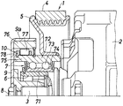
図5に示す自動車のエアコンディショナ用の圧縮機用プーリユニット(1)は、自動車エンジンのクランクシャフトにベルト(4)を介して接続されエンジンの動力を圧縮機(2)の回転軸(3)に伝達するもので、ベルト(4)が巻き掛けられたプーリ(5)と、プーリ(5)の内径側に配置されて圧縮機(2)の回転軸(3)に固定された中空軸(6)と、内輪(71)、外輪(72)、2列に配置された複数の玉(73)およびこれらの玉(73)を保持する保持器(74)を有しプーリ内径と中空軸外径との間に配置された複列転がり軸受(7)と、回転軸(3)端部に袋ナット(8)により固定されている有底円筒状ハブ(一方向クラッチ外輪の支持部材)(9)と、転がり軸受(7)の外輪(72)と一体の内輪(75)、外輪(76)、両輪(75)(76)間に配された複数のころ(77)、各ころ(77)を噛み込み方向へ付勢するコイルばね(図示略)および複数のころ(77)を保持するポケットを有する保持器(78)を有し転がり軸受(7)の外輪(71)外径とハブ(9)の円筒部(9a)内径との間に配置された一方向クラッチ(10)とを備えている。 A pulley unit (1) for a compressor for an automobile air conditioner shown in FIG. 5 is connected to a crankshaft of an automobile engine via a belt (4) and transmits the engine power to a rotating shaft (3) of the compressor (2). ), A pulley (5) around which a belt (4) is wound, and a hollow shaft arranged on the inner diameter side of the pulley (5) and fixed to the rotating shaft (3) of the compressor (2) (6), an inner ring (71), an outer ring (72), a plurality of balls (73) arranged in two rows, and a retainer (74) for holding these balls (73), and a pulley inner diameter and a hollow shaft Double-row rolling bearing (7) placed between the outer diameter and bottomed cylindrical hub (supporting member for one-way clutch outer ring) fixed to the end of the rotating shaft (3) by a cap nut (8) (9), the inner ring (75) integrated with the outer ring (72) of the rolling bearing (7), the outer ring (76), a plurality of rollers (77) disposed between the two rings (75) (76), each roller ( 77) and a coil spring (not shown) It has a cage (78) having a pocket for holding a plurality of rollers (77), and is arranged between the outer ring (71) outer diameter of the rolling bearing (7) and the cylindrical part (9a) inner diameter of the hub (9). And a one-way clutch (10).
一方向クラッチ(10)の外輪(76)は、ハブ(9)を介して回転軸(3)に一体化され、一方向クラッチ(10)の内輪(75)は、プーリ(5)に一体化されている。したがって、ベルト(4)によりプーリ(5)が回転駆動されて、一方向クラッチ(10)を介してプーリ(5)から圧縮機(2)の回転軸(3)に対して動力を伝達するに際し、一方向クラッチ(10)は、プーリ(5)の回転速度が圧縮機(2)の回転軸(3)よりも相対的に速くなると、ロック状態となって、プーリ(4)、ハブ(9)および回転軸(3)の三者を一体化して同期回転させ、プーリ(5)の回転速度が圧縮機(2)の回転軸(3)よりも相対的に遅くなると、フリー状態となって、プーリ(5)から圧縮機(2)の回転軸(3)に対する回転動力の伝達を遮断し、これにより、回転軸(3)が回転慣性力のみで回転を継続する。 The outer ring (76) of the one-way clutch (10) is integrated with the rotating shaft (3) via the hub (9), and the inner ring (75) of the one-way clutch (10) is integrated with the pulley (5). Has been. Accordingly, when the pulley (5) is rotationally driven by the belt (4) and power is transmitted from the pulley (5) to the rotating shaft (3) of the compressor (2) via the one-way clutch (10). The one-way clutch (10) is locked when the rotational speed of the pulley (5) is relatively faster than the rotational shaft (3) of the compressor (2), and the pulley (4), hub (9 ) And the rotating shaft (3) are integrated and rotated synchronously, and when the rotational speed of the pulley (5) becomes relatively slower than the rotating shaft (3) of the compressor (2), it enters a free state. Then, the transmission of the rotational power from the pulley (5) to the rotating shaft (3) of the compressor (2) is cut off, so that the rotating shaft (3) continues to rotate only with the rotary inertia force.
一般的な一方向クラッチは、過負荷が作用したときにベルトから圧縮機の回転軸に対する動力の伝達を遮断する機能は有していないため、過負荷時にプーリに対してベルトが滑り、ベルトが焼き付いたり、破損したりするという問題がある。そこで、この問題を解消するものとして、図示省略するが、特許文献1には、カム面上のロック位置を越えた領域に、ころが入り込むロック解除用凹部が形成されており、過負荷を受けたときに、ころが噛み込み部材として作用しない状態に拘束され、これにより、外輪と内輪とがフリー状態となって動力伝達が遮断されるトルクリミッタとしての動作が得られるトルクリミッタ付き一方向クラッチが提案されている。
上記特許文献1のトルクリミッタ付き一方向クラッチによると、過負荷時には、ころがロック解除用凹部に入り込むことによって、ロック状態が解消し、これにより、ベルトから圧縮機の回転軸に対する動力の伝達が遮断されるので、ベルトが焼き付いたり、破損したりする問題が解消されるが、より確実な動力遮断状態を確保するには、次のような課題が存在している。すなわち、トルクリミッタ作動時には、ころとこれを付勢しているコイルばねとの間に隙間が生じ、コイルばねを押さえるものがなくなるため、コイルばねがフリーとなって外輪と内輪との間に噛み込む可能性があり、この場合に、動力が再び伝達される状態となることが起こり得ることから、外輪と内輪との間へのコイルばねの噛み込みを防止する必要がある。 According to the one-way clutch with a torque limiter disclosed in Patent Document 1, when an overload is applied, the roller enters the unlocking recess, so that the locked state is eliminated, thereby transmitting power from the belt to the rotating shaft of the compressor. Since the belt is cut off, the problem of the belt burn-in or breakage is solved. However, the following problems exist to secure a more reliable power cut-off state. That is, when the torque limiter is activated, a gap is generated between the roller and the coil spring that biases the roller, and there is no need to hold the coil spring, so the coil spring becomes free and engages between the outer ring and the inner ring. In this case, it is possible that the power is transmitted again. Therefore, it is necessary to prevent the coil spring from being caught between the outer ring and the inner ring.
コイルばねを押さえるものがなくなったときに、コイルばねがフリーとなるのは、コイルばねを自由落下させることでばねの装着を行っているためであり、トルクリミッタがない一方向クラッチにおいても、装着の容易さを確保した上でコイルばねの脱落を防止することが課題となっている。 The reason why the coil spring becomes free when there is nothing to hold the coil spring is because the spring is mounted by allowing the coil spring to fall freely, even in a one-way clutch without a torque limiter. It is a problem to prevent the coil spring from falling off while ensuring the ease of the above.
この発明の目的は、コイルばねを確実に保持することができ、トルクリミッタ付きのものに適用した場合に、一旦トルクリミッタが作動して動力が遮断された後は、その動力遮断状態が確実に維持される一方向クラッチを提供することにある。 The object of the present invention is to reliably hold the coil spring, and when applied to the one with a torque limiter, once the torque limiter is actuated and the power is cut off, the power cut-off state is ensured. It is to provide a one-way clutch that is maintained.
この発明による一方向クラッチは、外輪、内輪、両軌道輪間に配された複数のころ、各ころを噛み込み方向へ付勢するコイルばねおよび各ころを保持する保持器を備えており、外輪および内輪のうちのいずれか一方の軌道輪に、ロック位置およびフリー位置を規定するカム面が形成されており、コイルばねをガイドするための突出状ばねガイドが保持器に設けられている一方向クラッチにおいて、ばねガイドに、カム面との隙間をコイルばねの線径よりも小さくするための突起が設けられ、突起の反対側のばねガイドの部分に、コイルばねを挿入しやすくするための凹部が形成されていることを特徴とするものである。 A one-way clutch according to the present invention includes an outer ring, an inner ring, a plurality of rollers arranged between both race rings, a coil spring that urges each roller in a biting direction, and a cage that holds each roller. One of the inner ring and the inner ring is provided with a cam surface defining a lock position and a free position, and a protruding spring guide for guiding the coil spring is provided in the cage. In the clutch, the spring guide is provided with a projection for making the gap with the cam surface smaller than the wire diameter of the coil spring, and a recess for facilitating insertion of the coil spring in the portion of the spring guide opposite to the projection Is formed.
コイルばねは、ばねガイドに先端部が突出するように嵌め入れられ、その先端面がころに当てられる。突起は、コイルばねの伸縮を妨げないように、コイルばねの一巻き目が引っかかる位置に設けられる。突起の反対側のばねガイドの部分に、コイルばねを挿入しやすくするための凹部が形成されていることにより、突起のある部分のばねガイドの径をコイルばねの内径よりも小さくすることができ、自由落下によってコイルばねを装着することが容易となる。 The coil spring is fitted into the spring guide so that the tip portion protrudes, and the tip surface is applied to the roller. The protrusion is provided at a position where the first turn of the coil spring is caught so as not to hinder expansion and contraction of the coil spring. By forming a recess to facilitate the insertion of the coil spring in the spring guide part on the opposite side of the protrusion, the diameter of the spring guide in the part with the protrusion can be made smaller than the inner diameter of the coil spring. It becomes easy to mount the coil spring by free fall.
この一方向クラッチは、例えば、ベルトが巻き掛けられたプーリと、プーリの内径側に配置された回転軸と、プーリ内径と回転軸外径との間に配置された転がり軸受と、転がり軸受の外輪と回転軸に固定された円筒状ハブ内径との間に配置された一方向クラッチとを備えているプーリユニット(動力伝達装置)における一方向クラッチとして好適に使用される。このようなプーリユニットは、自動車のエアコンディショナ用の圧縮機などの補機その他種々の装置において使用することができる。 This one-way clutch includes, for example, a pulley around which a belt is wound, a rotating shaft arranged on the inner diameter side of the pulley, a rolling bearing arranged between the inner diameter of the pulley and the outer diameter of the rotating shaft, and a rolling bearing. It is suitably used as a one-way clutch in a pulley unit (power transmission device) having a one-way clutch disposed between an outer ring and a cylindrical hub inner diameter fixed to a rotating shaft. Such a pulley unit can be used in an auxiliary machine such as a compressor for an air conditioner of an automobile and other various devices.
一方向クラッチの外輪、内輪およびころは金属製とされ、保持器は、合成樹脂製とされる。カム面は、内輪に形成されることがあり、また、外輪に形成されることもある。 The outer ring, inner ring and rollers of the one-way clutch are made of metal, and the cage is made of synthetic resin. The cam surface may be formed on the inner ring or may be formed on the outer ring.
一方向クラッチは、トルクリミッタ付きであってもよく、トルクリミッタ無しであってもよい。トルクリミッタ付き一方向クラッチは、例えば、カム面上のロック位置を越えた領域に、過負荷時にころが入り込むロック解除用凹部が形成されているものとされる。 The one-way clutch may be provided with a torque limiter or may not be provided with a torque limiter. In the one-way clutch with a torque limiter, for example, a lock-release concave portion into which a roller enters when overloaded is formed in a region beyond the lock position on the cam surface.
トルクリミッタ付きの一方向クラッチの場合、通常時には、ころは、保持器のポケット内にあって、ロック位置およびフリー位置の間を周方向に移動し、これにより、一方向クラッチとしての機能が果たされる。そして、異常時(過負荷時)には、ころは、その過大なトルクによって、カム面のロック解除用凹部に嵌まり込み、これにより、ロック状態が解除される。この際、コイルばねは、突起によってばねガイドからの脱落が防止され、コイルばねが脱落して内輪と外輪との間に噛み込むことはない。 In the case of a one-way clutch with a torque limiter, normally, the roller is in the cage pocket and moves in the circumferential direction between the locked position and the free position, thereby functioning as a one-way clutch. It is. In an abnormal state (overload), the roller is fitted into the unlocking recess of the cam surface by the excessive torque, thereby releasing the locked state. At this time, the coil spring is prevented from dropping from the spring guide by the protrusion, and the coil spring is not dropped and is not caught between the inner ring and the outer ring.
この発明の一方向クラッチによると、一旦組付けた後は、コイルばねが脱落することがないので、その後の作業が容易となり、トルクリミッタ付きとした場合には、コイルばねの脱落が防止されて、内輪と外輪との間にコイルばねが噛み込むことが防止されるので、一旦トルクリミッタが作動して動力が遮断された後は、その動力遮断状態が確実に維持される。 According to the one-way clutch of the present invention, once assembled, the coil spring does not fall off, so that the subsequent work is facilitated, and when the torque limiter is provided, the coil spring is prevented from falling off. Since the coil spring is prevented from biting between the inner ring and the outer ring, once the torque limiter is activated and the power is cut off, the power cut-off state is reliably maintained.
この発明の実施の形態を、以下図面を参照して説明する。 Embodiments of the present invention will be described below with reference to the drawings.
図1および図2は、この発明による一方向クラッチの第1実施形態を示している。 1 and 2 show a first embodiment of a one-way clutch according to the present invention.
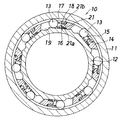
この一方向クラッチ(10)は、図5に示した一方向クラッチ(10)として使用されるもので、円筒形の外輪(11)と、多角形状に形成されてこの部分がロック位置およびフリー位置を規定するカム面(16)とされた内輪(12)と、カム面(16)と外輪(11)の内周面とで形成された楔状空間(17)に配置され、外輪(11)と内輪(12)とが一の方向(ロック方向)に相対回転することにより外輪(11)と内輪(12)との間に噛み込み、他の方向(フリー方向)に相対回転したとき噛み込みを解除する複数の噛み込み部材としてのころ(13)と、ころ(13)を噛み込み方向(楔状空間(17)の狭い側)に付勢するコイルばね(15)と、ころ(13)およびコイルばね(15)を収納するポケット(18)を有しておりころ(13)を楔状空間(17)内に位置させる環状の保持器(14)とを備えている。 This one-way clutch (10) is used as the one-way clutch (10) shown in FIG. 5, and is formed into a cylindrical outer ring (11) and a polygonal shape, and these portions are in a locked position and a free position. Is disposed in a wedge-shaped space (17) formed by the cam ring (16) defining the inner ring (12), the cam surface (16) and the inner peripheral surface of the outer ring (11), and the outer ring (11) When the inner ring (12) rotates relative to one direction (locking direction), the outer ring (11) engages with the inner ring (12), and when it rotates relative to the other direction (free direction) Roller (13) as a plurality of biting members to be released, coil spring (15) for biasing roller (13) in the biting direction (narrow side of wedge-shaped space (17)), roller (13) and coil It has a pocket (18) for accommodating the spring (15), and an annular cage (14) for positioning the roller (13) in the wedge-shaped space (17).
カム面(16)は、内輪(12)の外周面が横断面多角形状(図示は8角形)とされることにより形成されており、その各面(断面では辺)の反時計方向側部分と外輪(11)内周面との間が楔状空間(17)として使用されている。 The cam surface (16) is formed by forming the outer peripheral surface of the inner ring (12) to have a polygonal cross-sectional shape (an octagon in the figure), and a counterclockwise side portion of each surface (side in the cross-section) A space between the inner periphery of the outer ring (11) is used as a wedge-shaped space (17).
保持器(14)の各ポケット(18)の周方向長さは、ころ(13)の外径+コイルばね(15)の自由長よりも小さくなされている。これにより、ころ(13)とコイルばね(15)とは、ころ(13)の位置にかかわらず常に接触するようになされている。保持器(14)のポケット(18)の軸方向の寸法は、ころ(13)の軸方向長さよりも大きくなされており、これにより、ころ(13)は、ロック位置およびフリー位置の間をポケット(18)に案内されて移動することができる。 The circumferential length of each pocket (18) of the cage (14) is smaller than the outer diameter of the roller (13) + the free length of the coil spring (15). Thereby, the roller (13) and the coil spring (15) are always in contact with each other regardless of the position of the roller (13). The axial dimension of the cage (14) pocket (18) is larger than the axial length of the roller (13), so that the roller (13) is pocketed between the locked and free positions. Guided by (18) and can move.
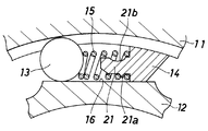
保持器(14)には、コイルばね(15)をガイドするための突出状ばねガイド(21)が設けられており、コイルばね(15)は、後述するようにして、ばねガイド(21)に嵌められている。ばねガイド(21)は、内輪(12)と外輪(11)とのちょうど中間よりも内輪(12)側に寄って設けられており、これにより、遠心力作用時に、コイルばね(15)が外輪(11)に接触することが防止されている。ばねガイド(21)の径方向内側部分には、カム面(16)との隙間をコイルばね(15)の線径よりも小さくするための突起(21a)が設けられており、ばねガイド(21)の径方向外側部分には、突起(21a)に対応する位置に、コイルばね(15)を挿入しやすくするための凹部(21b)が形成されている。 The cage (14) is provided with a protruding spring guide (21) for guiding the coil spring (15), and the coil spring (15) is connected to the spring guide (21) as described later. It is fitted. The spring guide (21) is provided closer to the inner ring (12) side than the middle between the inner ring (12) and the outer ring (11). Contact with (11) is prevented. On the radially inner part of the spring guide (21), a protrusion (21a) is provided to make the gap with the cam surface (16) smaller than the wire diameter of the coil spring (15). A concave portion (21b) for facilitating the insertion of the coil spring (15) is formed at a position corresponding to the protrusion (21a) in the radially outer portion of).
内輪(12)には、カム面(16)上のロック位置を越えた領域に、過負荷時にころ(13)が入り込むロック解除用凹部(19)が形成されている。 The inner ring (12) is formed with a lock release recess (19) in which the roller (13) enters when overloaded, in a region beyond the lock position on the cam surface (16).
この一方向クラッチ(10)によると、外輪(11)の回転速度が内輪(12)よりも相対的に速くなると、ころ(13)がくさび状空間(17)の狭い側(図の反時計方向)へ転動させられてロック状態となるので、外輪(11)と内輪(12)とが一体化して同期回転する。しかし、外輪(11)の回転速度が内輪(12)よりも相対的に遅くなると、ころ(13)がくさび状空間(17)の広い側(図の時計方向)へ転動させられてフリー状態となるので、外輪(11)から内輪(12)へ回転動力の伝達が遮断されることになって内輪(12)が回転慣性力のみで回転を継続するようになる。こうして、通常の状態(一方向クラッチ作動状態)では、ころ(13)は、ロック位置とフリー位置とに移動可能であり、大きなトルク負荷がかかると、ころ(13)は、内輪(12)と外輪(11)との間に噛み込んだ状態で、楔状空間(17)のより狭い方向に強制的に移動させられる。ころ(13)がロック解除用凹部(19)に嵌まり込むと、内輪(12)と外輪(11)とはフリー状態となる。 According to this one-way clutch (10), when the rotational speed of the outer ring (11) is relatively higher than that of the inner ring (12), the roller (13) moves to the narrow side of the wedge-shaped space (17) (counterclockwise in the figure). The outer ring (11) and the inner ring (12) are integrated and rotate synchronously. However, when the rotation speed of the outer ring (11) becomes relatively slower than the inner ring (12), the roller (13) is rolled to the wide side (clockwise in the figure) of the wedge-shaped space (17) and is free. Therefore, transmission of rotational power from the outer ring (11) to the inner ring (12) is interrupted, and the inner ring (12) continues to rotate only with the rotational inertia force. Thus, in a normal state (one-way clutch operation state), the roller (13) can move between the locked position and the free position, and when a large torque load is applied, the roller (13) becomes the inner ring (12). It is forced to move in a narrower direction of the wedge-shaped space (17) in a state of being bitten between the outer ring (11). When the roller (13) is fitted into the unlocking recess (19), the inner ring (12) and the outer ring (11) are in a free state.
したがって、この一方向クラッチ(10)を備えた圧縮機用プーリユニット(図5参照)によると、例えば圧縮機(2)の焼き付き故障などに伴い回転軸(3)の回転に異常が生じると、一方向クラッチ(10)の負荷トルクが増大し、この値が所要の規定値(例えば60Nm)に到達すると、ころ(13)は、くさび状空間(17)におけるロック位置のさらに狭い側(図の反時計方向)へ移動させられて、カム面(16)のロック解除用凹部(19)に入り込む。これに伴い、ころ(13)は、両輪(11)(12)間に噛み込むことが不可能となり、プーリ(5)から圧縮機(2)の回転軸(3)に対する動力伝達が遮断されるトルクリミッタの機能が果たされる。この結果、過負荷を受けたときでもプーリ(5)の回転が継続し、クランクシャフトの回転損失を生じることなく、プーリ(5)上でベルト(4)が滑らずに済んでベルト(4)の寿命が向上し、圧縮機(2)やベルト(4)を通じて連結される機器に悪影響を及ぼさずに済む。 Therefore, according to the compressor pulley unit (see FIG. 5) provided with the one-way clutch (10), for example, when an abnormality occurs in the rotation of the rotating shaft (3) due to a seizure failure of the compressor (2), When the load torque of the one-way clutch (10) increases and this value reaches a required specified value (for example, 60 Nm), the roller (13) moves to the narrower side of the locking position in the wedge-shaped space (17) (in the figure). It is moved counterclockwise) and enters the unlocking recess (19) of the cam surface (16). As a result, the rollers (13) cannot be engaged between the two wheels (11) and (12), and the power transmission from the pulley (5) to the rotating shaft (3) of the compressor (2) is cut off. The function of the torque limiter is fulfilled. As a result, even when overloaded, the pulley (5) continues to rotate, causing no rotation loss of the crankshaft and preventing the belt (4) from slipping on the pulley (5). The service life of the compressor is improved, and the devices connected through the compressor (2) and the belt (4) are not adversely affected.
コイルばね(15)がフリーになると、コイルばね(15)が内輪(12)と外輪(11)との間に噛み込むことによってロック状態に戻る可能性があるが、コイルばね(15)は、突起(21a)によってばねガイド(21)からの脱落が防止されており、コイルばね(15)が内輪(12)と外輪(11)との間に噛み込むことはない。コイルばね(15)がフリーにならないようにその自由長を長くすることには限界があるが、コイルばね(15)の脱落を防止することで、コイルばね(15)の自由長は従来と同じにして、コイルばね(15)をトルクリミッタ作動時においても拘束することができる。 When the coil spring (15) becomes free, the coil spring (15) may return to the locked state by being caught between the inner ring (12) and the outer ring (11), but the coil spring (15) The protrusion (21a) prevents the spring guide (21) from falling off, and the coil spring (15) does not get caught between the inner ring (12) and the outer ring (11). There is a limit to increasing the free length so that the coil spring (15) does not become free, but by preventing the coil spring (15) from falling off, the free length of the coil spring (15) is the same as before. Thus, the coil spring (15) can be restrained even when the torque limiter is operated.
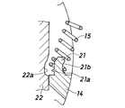
上記一方向クラッチ(10)を組み立てるには、図3に示すように、内輪(12)に相当する治具(22)を使用することとし、治具(22)に保持器(14)を組み込んだ後にコイルばね(15)をばねガイド(21)に嵌め入れるようにする。治具(22)には、ばねガイド(21)の突起(21a)に対応する部分に凹部(22a)を形成しておき、これにより、従来と同様の自由落下によってコイルばね(15)をばねガイド(21)に容易に嵌め入れることができる。 In order to assemble the one-way clutch (10), as shown in FIG. 3, a jig (22) corresponding to the inner ring (12) is used, and the cage (14) is assembled into the jig (22). After that, the coil spring (15) is fitted into the spring guide (21). In the jig (22), a recess (22a) is formed in a portion corresponding to the protrusion (21a) of the spring guide (21), so that the coil spring (15) can be It can be easily fitted into the guide (21).
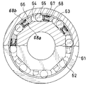
図4は、この発明による一方向クラッチの第2実施形態を示している。 FIG. 4 shows a second embodiment of the one-way clutch according to the present invention.
この一方向クラッチは、円筒形の外輪(61)と、多角形状に形成されてこの部分がカム面(63)とされた内輪(62)と、カム面(63)と外輪(61)の内周面とで形成された楔状空間(64)に配置されたころ(65)と、ころ(65)を保持する環状の保持器(66)と、ころ(65)を楔状空間(64)の狭い側(ロック側)へ付勢するコイルばね(67)とを備えている。コイルばね(67)は、楔状空間(64)方向に突出するように保持器(66)に設けられたばねガイド(68)に装着されている。 The one-way clutch includes a cylindrical outer ring (61), an inner ring (62) formed in a polygonal shape and having this portion as a cam surface (63), and an inner ring between the cam surface (63) and the outer ring (61). A roller (65) disposed in a wedge-shaped space (64) formed by the peripheral surface, an annular cage (66) for holding the roller (65), and a roller (65) having a narrow wedge-shaped space (64) And a coil spring (67) for urging to the side (lock side). The coil spring (67) is attached to a spring guide (68) provided in the cage (66) so as to protrude in the wedge-shaped space (64) direction.
ばねガイド(68)の径方向内側部分には、カム面(63)との隙間をコイルばね(67)の線径よりも小さくするための突起(68a)が設けられており、ばねガイド(68)の径方向外側部分には、突起(68a)に対応する位置に、コイルばね(67)を挿入しやすくするための凹部(68b)が形成されている。この一方向クラッチによると、図3に示したようにしてコイルばね(67)を容易にばねガイド(68)に挿入することができ、これにより、装着の容易さを確保した上で、以後の作業(保持器アッシーの内外輪間への組み込みなど)において、コイルばね(67)の脱落を防止することができる。 A protrusion (68a) is provided on the radially inner portion of the spring guide (68) to make the gap with the cam surface (63) smaller than the wire diameter of the coil spring (67). A concave portion (68b) for facilitating insertion of the coil spring (67) is formed at a position corresponding to the protrusion (68a) in the radially outer portion of). According to this one-way clutch, as shown in FIG. 3, the coil spring (67) can be easily inserted into the spring guide (68). The coil spring (67) can be prevented from falling off during work (such as assembling the cage assembly between the inner and outer rings).
なお、上記実施形態において、一方向クラッチ(10)は、自動車のエアコンディショナ用の圧縮機用プーリユニット用として説明したが、一方向クラッチの用途はこれに限定されるものではない。また、上記の一方向クラッチは、内輪にカム面が形成されているものであるが、上記のばねガイドに突起を設ける構成は、外輪にカム面が形成されている一方向クラッチにも同様に適用することができる。 In the above embodiment, the one-way clutch (10) has been described as a compressor pulley unit for an air conditioner of an automobile. However, the use of the one-way clutch is not limited to this. The one-way clutch described above has a cam surface formed on the inner ring, but the configuration in which the protrusion is provided on the spring guide similarly applies to the one-way clutch formed on the outer ring. Can be applied.
(10) 一方向クラッチ
(11)(61) 外輪
(12)(62) 内輪
(13)(65) ころ
(14)(66) 保持器
(15)(67) コイルばね
(16)(63) カム面
(19) 凹部
(21)(68) ばねガイド
(21a)(68a) 突起
(21b)(68b) 凹部
(10) One-way clutch
(11) (61) Outer ring
(12) (62) Inner ring
(13) (65)
(14) (66) Cage
(15) (67) Coil spring
(16) (63) Cam surface
(19) Recess
(21) (68) Spring guide
(21a) (68a) Projection
(21b) (68b) Recess
Claims (3)
ばねガイドに、カム面との隙間をコイルばねの線径よりも小さくするための突起が設けられ、突起の反対側のばねガイドの部分に、コイルばねを挿入しやすくするための凹部が形成されていることを特徴とする一方向クラッチ。 The outer ring, the inner ring, a plurality of rollers arranged between the two race rings, a coil spring that urges each roller in the biting direction, and a cage that holds each roller, and either one of the outer ring or the inner ring In the one-way clutch, a cam surface defining a lock position and a free position is formed on the raceway ring, and a protruding spring guide for guiding the coil spring is provided in the cage.
The spring guide is provided with a projection for making the gap with the cam surface smaller than the wire diameter of the coil spring, and a recess for facilitating insertion of the coil spring is formed in the portion of the spring guide opposite to the projection. One-way clutch characterized by that.
Priority Applications (1)
| Application Number | Priority Date | Filing Date | Title |
|---|---|---|---|
| JP2006292795A JP2008106913A (en) | 2006-10-27 | 2006-10-27 | One-way clutch |
Applications Claiming Priority (1)
| Application Number | Priority Date | Filing Date | Title |
|---|---|---|---|
| JP2006292795A JP2008106913A (en) | 2006-10-27 | 2006-10-27 | One-way clutch |
Publications (1)
| Publication Number | Publication Date |
|---|---|
| JP2008106913A true JP2008106913A (en) | 2008-05-08 |
Family
ID=39440421
Family Applications (1)
| Application Number | Title | Priority Date | Filing Date |
|---|---|---|---|
| JP2006292795A Withdrawn JP2008106913A (en) | 2006-10-27 | 2006-10-27 | One-way clutch |
Country Status (1)
| Country | Link |
|---|---|
| JP (1) | JP2008106913A (en) |
Cited By (1)
| Publication number | Priority date | Publication date | Assignee | Title |
|---|---|---|---|---|
| JP2010151129A (en) * | 2008-12-15 | 2010-07-08 | Zen Sa Industria Metalurgica | Starter plate having wheel system not receiving friction of roller |
-
2006
- 2006-10-27 JP JP2006292795A patent/JP2008106913A/en not_active Withdrawn
Cited By (1)
| Publication number | Priority date | Publication date | Assignee | Title |
|---|---|---|---|---|
| JP2010151129A (en) * | 2008-12-15 | 2010-07-08 | Zen Sa Industria Metalurgica | Starter plate having wheel system not receiving friction of roller |
Similar Documents
| Publication | Publication Date | Title |
|---|---|---|
| US8944947B2 (en) | Pulley unit | |
| US8393452B2 (en) | One way clutch | |
| JP2008082508A (en) | Pulley unit | |
| JP2003035357A (en) | Driving force transmission device | |
| JP4888009B2 (en) | One-way clutch with torque limiter | |
| US20190226535A1 (en) | Clutch device | |
| JP2008082457A (en) | One-way clutch with torque limiter | |
| JP2008106913A (en) | One-way clutch | |
| JP4770677B2 (en) | One-way clutch with torque limiter | |
| JP2008082456A (en) | One-way clutch with torque limiter | |
| JP2008106914A (en) | Pulley unit provided with one-way clutch | |
| WO2017204183A1 (en) | Clutch device | |
| JP4923919B2 (en) | One-way clutch with torque limiter | |
| JP2006144812A (en) | Sealing device | |
| JP2006307922A (en) | One-way clutch | |
| JP4940994B2 (en) | One-way clutch | |
| JP2006097710A (en) | One-way clutch | |
| JP2010007825A (en) | One-way clutch | |
| JP2007162814A (en) | One-way clutch built-in type pulley device | |
| JP4893997B2 (en) | One-way clutch | |
| JP2006161951A (en) | Pulley unit with one-way clutch | |
| JP2008185049A (en) | Pulley unit | |
| US20080190728A1 (en) | One-way clutch | |
| JP2008164034A (en) | One-way clutch and one-way clutch unit | |
| JP4617610B2 (en) | Pulley unit |
Legal Events
| Date | Code | Title | Description |
|---|---|---|---|
| A300 | Withdrawal of application because of no request for examination |
Free format text: JAPANESE INTERMEDIATE CODE: A300 Effective date: 20100105 |