JP4940994B2 - One-way clutch - Google Patents
One-way clutch Download PDFInfo
- Publication number
- JP4940994B2 JP4940994B2 JP2007043338A JP2007043338A JP4940994B2 JP 4940994 B2 JP4940994 B2 JP 4940994B2 JP 2007043338 A JP2007043338 A JP 2007043338A JP 2007043338 A JP2007043338 A JP 2007043338A JP 4940994 B2 JP4940994 B2 JP 4940994B2
- Authority
- JP
- Japan
- Prior art keywords
- roller
- way clutch
- wedge
- ring body
- Prior art date
- Legal status (The legal status is an assumption and is not a legal conclusion. Google has not performed a legal analysis and makes no representation as to the accuracy of the status listed.)
- Expired - Fee Related
Links
Images


Description
この発明は、径方向内外に同心状に配設される内輪体と外輪体とを同期回転させるロック状態と相対回転させるフリー状態とに切り換える一方向クラッチに関する。 The present invention relates to a one-way clutch that switches between a locked state in which an inner ring body and an outer ring body that are concentrically arranged inside and outside in a radial direction are synchronously rotated and a free state in which the inner ring body is relatively rotated.
この種の一方向クラッチは、例えば、エンジンの補機類(オルタネータ、エアコンディショナ用コンプレッサ、ウオーターポンプ、冷却ファン等)に使用されるプーリユニットに組み付けられる場合がある。
この場合、エンジンのクランクシャフトのトルクが伝達される伝動ベルトが掛け渡されるプーリと、補機類としてのオルタネータのロータ(ロータ軸)に一体回転可能に連結される軸体との間に配設され、プーリから軸体へトルクを伝達させたり遮断させる。
また、一方向クラッチは、内輪体(ロータに対応する軸体自身で構成される場合がある)と、外輪体(プーリ自身で構成される場合がある)との対向周面の間に、複数のくさび状空間が周方向に所定間隔を隔てて形成される。そして、これら複数のくさび空間には、これと同数のローラと、これら各ローラをくさび状空間の狭い側へ個別に付勢するコイルばねとが保持器のポケットに収納された状態で配設された構造のものが知られている(例えば、特許文献1参照)。
この種の一方向クラッチにおいて、ローラの両端面と、保持器のポケットの両側壁内面との間に隙間がなく、接触状態に保たれると、ローラの傾動が拘束される。この状態で、コイルばねの弾発力(付勢力)によってローラがくさび状空間の狭い側(ロック状態となる側)に移動すると、くさび状空間の狭い側のくさび面に対しローラが片当たりした状態(相対的に傾いた状態)で噛み込む恐れがある。
このため、くさび状空間のくさび面やローラの加工精度のバラツキ等を考慮して、ローラの両端面と、保持器のポケットの両側壁内面との対向面の間には、ローラの傾動(僅かな角度の傾動)を許容する隙間が設定される。これによって、くさび状空間のくさび面やローラの加工精度にバラツキ等があったとしても、ローラがくさび状空間の狭い側のくさび面に良好に噛み込んでトルク伝達するようになっている。
In this case, it is arranged between a pulley around which a transmission belt for transmitting the torque of the crankshaft of the engine is stretched and a shaft body that is connected to a rotor (rotor shaft) of an alternator as auxiliary equipment so as to be integrally rotatable. Then, torque is transmitted from the pulley to the shaft body or cut off.
The one-way clutch includes a plurality of one-way clutches between opposing circumferential surfaces of an inner ring body (which may be configured by a shaft body corresponding to the rotor itself) and an outer ring body (which may be configured by a pulley itself). The wedge-shaped spaces are formed at predetermined intervals in the circumferential direction. In the plurality of wedge spaces, the same number of rollers and coil springs for individually urging each roller toward the narrow side of the wedge-shaped space are disposed in a state of being accommodated in the pockets of the cage. A structure having a different structure is known (for example, see Patent Document 1).
In this type of one-way clutch, if there is no gap between both end surfaces of the roller and the inner surfaces of both side walls of the cage pocket, the tilting of the roller is restrained if the contact state is maintained. In this state, when the roller is moved to the narrow side of the wedge-shaped space (the locked state) by the elastic force (biasing force) of the coil spring, the roller hits the wedge surface on the narrow side of the wedge-shaped space. There is a risk of biting in a state (relatively inclined state).
For this reason, in consideration of the wedge surface of the wedge-shaped space and variations in the processing accuracy of the roller, the roller tilts slightly between the opposite surfaces of the roller end surfaces and the inner surfaces of both side walls of the cage pocket. A clearance that allows a tilt of a certain angle) is set. As a result, even if there are variations in the wedge surface of the wedge-shaped space and the processing accuracy of the rollers, the roller is well engaged with the wedge surface on the narrow side of the wedge-shaped space to transmit torque.
ところで、前記した従来の一方向クラッチにおいては、内輪体と外輪体とが相対回転するフリー状態にある場合、くさび状空間内でローラが外輪体又は内輪体の軌道面を滑り、スティックスリップ(自励振動)を起こし、これによって異音が発生する恐れがある。
例えば、エンジンの補機類の一つであるオルタネータのプーリユニットに一方向クラッチが使用された場合、エンジンの停止にともなってプーリ(外輪体)の回転が停止したときには、一方向クラッチのローラがロック位置から外れてくさび状空間の広い側へ移動してフリー状態に切替わる。これにより、プーリからのトルクの伝達が遮断されるが、オルタネータのロータの軸体(内輪体)は、ロータが大きな回転慣性を有するため、遮断以降も慣性力が消失するまで回転を継続する。
そして、エンジン停止の静かな状態の中で、オルタネータのロータの軸体(内輪体)の回転が止まる直前において、ローラがスティックスリップを起こしやすいため、スティックスリップによる異音が聞こえやすいという問題点があった。
By the way, in the conventional one-way clutch described above, when the inner ring body and the outer ring body are in a free state in which the inner ring body and the outer ring body rotate relative to each other, the roller slides on the raceway surface of the outer ring body or the inner ring body in the wedge-shaped space. Exciting vibration) may occur, which may cause abnormal noise.
For example, when a one-way clutch is used in a pulley unit of an alternator, which is one of the engine accessories, when the rotation of the pulley (outer ring body) stops when the engine stops, the roller of the one-way clutch It moves from the locked position to the wide side of the wedge-shaped space and switches to the free state. Thereby, the transmission of torque from the pulley is interrupted, but the shaft body (inner ring body) of the rotor of the alternator continues to rotate until the inertial force disappears after the interruption because the rotor has a large rotational inertia.
And in a quiet state where the engine is stopped, the roller easily causes stick-slip just before the rotation of the shaft body (inner ring body) of the alternator rotor. there were.
この発明の目的は、前記問題点に鑑み、ローラのスティックスリップを抑制して異音の発生を防止することができる一方向クラッチを提供することである。 In view of the above problems, an object of the present invention is to provide a one-way clutch capable of preventing the occurrence of abnormal noise by suppressing stick slip of a roller.
前記目的を達成するために、この発明の請求項1に係る一方向クラッチは、径方向内外に同心状に配設される内輪体と外輪体とを同期回転させるロック状態と相対回転させるフリー状態とに切り換える一方向クラッチであって、
前記内輪体と前記外輪体との対向周面の間には複数のくさび状空間が周方向に所定間隔を隔てて形成され、
前記複数のくさび空間には、これと同数のローラと、これら各ローラを前記くさび状空間に噛み込むロック方向に個別に付勢するコイルばねとが保持器のポケットに収納された状態で配設され、
前記ローラの軸線方向両端面と、前記ポケットの軸線方向両側壁内面との対向面のうち、一方の面には、他方の面に点接触した状態で前記ローラを傾動可能に保持する接触部としての凸部が設けられ、
前記ポケットに前記ローラが組み付けられたときには、前記凸部によって前記ポケットの両側壁を弾性的に撓ませることによって前記ローラを弾性的に保持する構成にしてあることを特徴とする。
In order to achieve the object, the one-way clutch according to claim 1 of the present invention is a free state in which the inner ring body and the outer ring body, which are concentrically disposed inside and outside in the radial direction, are synchronously rotated with the locked state. A one-way clutch that switches between
A plurality of wedge-shaped spaces are formed at predetermined intervals in the circumferential direction between the opposed peripheral surfaces of the inner ring body and the outer ring body,
In the plurality of wedge spaces, the same number of rollers and coil springs individually energizing the rollers in the locking direction for engaging each of the rollers in the wedge-shaped spaces are arranged in a state of being accommodated in the pockets of the cage. And
As a contact portion that holds the roller in a tiltable manner on one surface of the opposing surfaces of the both axial end surfaces of the roller and the inner surfaces of both side walls in the axial direction of the pocket while being in point contact with the other surface. projections provided, et al are of
When the roller is assembled in the pocket, the roller is elastically held by elastically deflecting both side walls of the pocket by the convex portion .
前記構成によると、ローラの両端面と、ポケットの両側壁内面との対向面において、一方の面に設けられた接触部としての凸部が他方の面に点接触した状態でローラを傾動可能に保持することができる。
そして、くさび状空間のくさび面やローラの加工精度のバラツキ等があったとしても、ローラの傾動によってくさび状空間の狭い側のくさび面に良好に噛み込んでトルク伝達することができる。
特に、接触部としての凸部によってポケットの両側壁を弾性的に撓ませることによってローラを弾性的に保持することができる。これによって、スティックスリップを抑制することができ、異音の発生を防止することができる。
According to the above construction, the end surfaces of the roller, the surface facing the side walls the inner surface of the pocket, the roller can be tilted in a state in which the convex portion is touched point contact with the other surface of the contact portion provided on one surface Can be held in.
Even if there is a variation in the wedge surface of the wedge-shaped space or the processing accuracy of the roller, it is possible to transmit the torque by properly engaging the wedge surface on the narrow side of the wedge-shaped space by the tilting of the roller.
In particular, the roller can be elastically held by elastically deflecting both side walls of the pocket by the convex portion as the contact portion. Thereby, stick-slip can be suppressed and generation of abnormal noise can be prevented.
請求項2に係る一方向クラッチは、請求項1に記載の一方向クラッチであって、
接触部としての凸部は、保持器のポケットの両側壁内面に突設されていることを特徴とする。
前記構成によると、保持器を金属板材のプレス加工によって形成する場合には、保持器の各ポケットの両側壁内面に接触部としての凸部をプレス加工によって容易に形成することが可能となる。
また、保持器を合成樹脂の射出成形によって形成する場合には、射出成形と同時に接触部としての凸部を形成することが可能となる。
前記したように、保持器の各ポケットの両側壁内面に接触部としての凸部を形成することによってコスト低減を図ることが可能となる。
The one-way clutch according to claim 2 is the one-way clutch according to claim 1,
The convex portion of the contact portion, characterized in that it is protruded from the side walls the inner surface of the pocket of the cage.
According to the said structure, when forming a holder | retainer by the press work of a metal plate material, it becomes possible to form easily the convex part as a contact part by press work in the inner surface of the both sides of each pocket of a holder | retainer.
Further, when the cage is formed by injection molding of synthetic resin, it is possible to form a convex portion as a contact portion simultaneously with the injection molding.
As described above, it is possible to reduce costs by forming convex portions as contact portions on the inner surfaces of both side walls of each pocket of the cage.
請求項3に係る一方向クラッチは、請求項1に記載の一方向クラッチであって、
接触部としての凸部は、ローラの両端面の略中心部に突設されていることを特徴とする。
前記構成によると、ローラの両端面の略中心部に接触部としての凸部が形成されることによって、ローラを常に安定した状態で傾動可能に保持することができる。ひいては、くさび状空間のくさび面やローラの加工精度のバラツキ等があったとしても、ローラの安定した傾動によってくさび状空間の狭い側のくさび面に良好に噛み込むことができると共に、ローラのスティックスリップの抑制に効果が大きい。
The one-way clutch according to claim 3 is the one-way clutch according to claim 1,
The convex portion of the contact portion, characterized in that it is projected from the substantially central portion of the end surfaces of the roller.
According to the said structure, the convex part as a contact part is formed in the approximate center part of the both end surfaces of a roller, and a roller can always be hold | maintained so that tilting is possible in the stable state. As a result, even if there is a variation in the wedge surface of the wedge-shaped space or the processing accuracy of the roller, the roller can be satisfactorily engaged with the wedge surface on the narrow side of the wedge-shaped space by the stable tilting of the roller, and the stick of the roller Greatly effective in suppressing slip.
次に、この発明を実施するための最良の形態を実施例にしたがって説明する。 Next, the best mode for carrying out the present invention will be described with reference to examples.
(実施例1)
この発明の実施例1を図1〜図4にしたがって説明する。
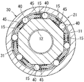
図1はこの発明の実施例1に係る一方向クラッチを備えたプーリユニットを示す側断面図である。図2は図1のII−II線に基づく断面図である。図3は保持器のポケットにローラ及びコイルばねが収納された状態を拡大して示す平面図である。図4は保持器のポケットにローラ及びコイルばねが収納された状態を拡大して示す側面図である。
図1に示すように、この実施例1に係る一方向クラッチを備えたプーリユニットは、車載用エンジンの補機類の一つであるオルタネータに使用される場合を例示するものであり、軸体11、プーリ21、一方向クラッチ30、玉軸受50、ころ軸受55及びシール部材58、59を備える。
Example 1
A first embodiment of the present invention will be described with reference to FIGS.
1 is a side sectional view showing a pulley unit including a one-way clutch according to Embodiment 1 of the present invention. FIG. 2 is a cross-sectional view based on the line II-II in FIG. FIG. 3 is an enlarged plan view showing a state where rollers and coil springs are housed in the pockets of the cage. FIG. 4 is an enlarged side view showing a state in which a roller and a coil spring are stored in a pocket of the cage.
As shown in FIG. 1, the pulley unit including the one-way clutch according to the first embodiment exemplifies a case where the pulley unit is used for an alternator that is one of auxiliary components of an in-vehicle engine. 11, a
図1と図2に示すように、軸体11は、オルタネータのロータのロータ軸(図示しない)の先端部軸回りに取り付けられる筒軸状に形成されている。そして、軸体11の内孔の軸方向略中央部には、ロータ軸の先端側に形成された雄ねじ部に締め付けられる雌ねじ12が形成され、軸体11の内孔の一端側開口部には、六角棒等の締付工具が嵌合可能な六角穴形状の締付凹部13が形成されている。
また、この実施例1において、軸体11は、一方向クラッチ30、玉軸受50、及びころ軸受55のそれぞれの内輪体を構成している。
As shown in FIGS. 1 and 2, the
In the first embodiment, the
図1と図2に示すように、プーリ21は、軸体11の外周に同心に配置され、一方向クラッチ30、玉軸受50、及びころ軸受55のそれぞれの外輪体を構成するとともに、その外周面には伝動ベルト8が掛け渡される断面波形状のベルト溝22が形成されている。なお、伝動ベルト8は、エンジンのクランクシャフトのプーリに掛け渡され、クランクシャフトのトルクをプーリ21に伝達するようになっている。
As shown in FIGS. 1 and 2, the
図1と図2に示すように、一方向クラッチ30は、内輪体としての軸体11と、外輪体としてのプーリ21と、これら軸体11とプーリ21との間の環状空間の軸方向中央領域において、円周方向に所定間隔を隔てて配設された複数のローラ40と、これらローラ40をロック方向に個別に付勢するコイルばね45と、複数のローラ40及びコイルばね45を保持する保持器31とを備えている。
すなわち、軸体11とプーリ21との対向周面の間には複数(図では8個)のくさび状空間が周方向に所定間隔を隔てて形成され、これら複数のくさび空間には、これと同数のローラ40と、これら各ローラ40をロック方向(くさび空間の狭い側)に個別に付勢するコイルばね45とが保持器31の各ポケット34に収納された状態でそれぞれ配設されている(図3参照)。
この実施例1において、軸体11の外周面には、複数のくさび空間を形成するために、複数のくさび空間と同数の平坦面(又は曲面)のカム面15が周方向に形成され、これによって軸体11の外周面があたかも正多角形(図2では正8角形)をなす一方、プーリ21の内周面は円形をなしている。
また、コイルばね45はばね線材が楕円形状、矩形形状等に巻回されて形成されている。
As shown in FIGS. 1 and 2, the one-
That is, a plurality (eight in the figure) of wedge-shaped spaces are formed at predetermined intervals in the circumferential direction between the opposed peripheral surfaces of the
In the first embodiment, on the outer peripheral surface of the
The
図3と図4に示すように、保持器31は、ローラ40の軸線方向両端面に所定の隙間を保って軸体11の外周面に嵌合固定(例えば圧入固定)される多角形状の内孔が中心部にそれぞれ貫設された一対の端板32と、これら一対の端板32の間に複数のポケット34を区画形成する柱部35とを一体に備えて形成されている。
保持器31の各柱部35の一側面(くさび空間の狭い側に対向する面)には、コイルばね45の基端巻回部が嵌挿される突起36が突設されている。
そして、コイルばね45は、その基端巻回部が柱部35の突起36に嵌挿され、その突起36の根元部をばね座として支持された状態で先端巻回部がローラ40の外周面に当接して、ローラ40を軸体11のカム面15とプーリ21の内周面とで形成されるくさび状空間の狭い側(ロック状態となる側)に弾発付勢している。
As shown in FIGS. 3 and 4, the
On one side surface (the surface facing the narrow side of the wedge space) of each
The
図3と図4に示すように、ローラ40の軸線方向両端面41と、ポケット34の軸線方向両側壁内面(端板32の内面)32aとの対向面のうち、一方の面には、他方の面に局部的に接触した状態でローラ40を傾動可能に保持する接触部としての凸部48が設けられている。
この実施例1においては、ポケット34の両側壁内面32aの間隔寸法は、ローラ40の長さ寸法よりも適宜に大きく設定され、これら両側壁内面32aに、断面円弧状、半球状等の凸部48が突設されている。
As shown in FIGS. 3 and 4, one of the opposing surfaces of the axial end surfaces 41 of the
In the first embodiment, the interval dimension between the side wall
また、ポケット34の両側壁内面32aの凸部48の相対する先端の間の間隔寸法は、ローラ40の長さ寸法よりも若干小さく設定され、これによって、ローラ40の長さ寸法にバラツキがあったとしても、ポケット34にローラ40が組み付けられたときには、両凸部48がローラ40の両端面に点接触状態で確実に接触するようになっている。
さらに、ポケット34にローラ40が組み付けられたときには、両凸部48によってポケット34の両側壁(一対の端板32)を僅かではあるが弾性的に撓ませることによってローラ40を弾性的に保持するようになっている。
また、ポケット34の両側壁(一対の端板32)の板厚や板幅を小さくし、これによってばね定数を小さくすることで、両凸部48の相対する先端の間の間隔寸法、ローラ40の長さ寸法等のバラツキによる両凸部48とローラ40の両端面41との間の摩擦力が変化しにくいように設定することが望ましい。
なお、コイルばね45によるローラ40の弾発力(付勢力)は、ポケット34の両側壁内面32aの凸部48と、ローラ40の両端面41との相互の接触摩擦力に抗してローラ40をくさび状空間の狭い側(ロック状態となる側)のくさび面に噛み込む状態まで押し付け得るように設定される。
In addition, the distance between the opposite ends of the
Further, when the
Further, by reducing the thickness and width of both side walls (a pair of end plates 32) of the
Note that the elastic force (biasing force) of the
また、保持器31は、金属板材のプレス加工や合成樹脂材の射出成形によって一体に形成されている。
保持器31が金属板材のプレス加工によって形成される場合には、保持器31の各ポケット34の両側壁内面32aに接触部としての凸部48がプレス加工によって形成される。
また、保持器31が合成樹脂材の射出成形によって形成される場合には、射出成形と同時に接触部としての凸部48が形成される。
The
When the
Further, when the
図1に示すように、軸体11とプーリ21との間の環状空間において、一方向クラッチ30の保持器31の両側方のうちの一方には転がり軸受としての玉軸受51を構成する複数の玉52が保持器53によって保持された状態で転動可能に配設されている。さらに、保持器31の両側方のうちの他方には転がり軸受としてのころ軸受56を構成する複数のころ57が保持器58によって保持された状態で転動可能に配設されている。
また、環状空間の両開口部近傍には、環状空間を密封するシールリング60、61が装着されている。
As shown in FIG. 1, in an annular space between the
Further, seal rings 60 and 61 for sealing the annular space are mounted in the vicinity of both openings of the annular space.
この実施例1に係る一方向クラッチを備えたプーリユニットは上述したように構成される。
したがって、プーリ21の回転速度が軸体11の回転速度よりも速くなると、一方向クラッチ30がロック状態となるので、軸体11はプーリ21と一体回転する。
また、ローラ40がくさび状空間の狭い側へ噛み込んでロック状態となる際、くさび状空間のくさび面やローラ40の加工精度のバラツキ等があったとしても、ポケット34の両側壁内面32aの凸部48間に保持されたローラ40の傾動によって、くさび状空間の狭い側のくさび面にローラ40が良好に噛み込んでトルク伝達することができる。
The pulley unit including the one-way clutch according to the first embodiment is configured as described above.
Accordingly, when the rotational speed of the
Further, when the
また、プーリ21の回転速度が軸体11の回転速度よりも遅くなると、一方向クラッチ30のローラ40がロック位置から外れてくさび状空間の広い側へ移動してフリー状態に切替わる。これにより、プーリ21からのトルクの伝達が遮断されるが、オルタネータのロータに対応する軸体11はオルタネータのロータが大きな回転慣性を有するため、遮断以降も回転を継続する。
特に、エンジンを停止したときには、この停止にともなってプーリ(外輪体)の回転が停止し、軸体11はオルタネータのロータの回転慣性力が消失するまで回転を継続する。
そして、エンジン停止の静かな状態の中で、軸体11の回転が止まる直前、例えば、軸体11の回転が800rpm/min以下に達した後、停止する間において、ローラ40がスティックスリップを起こしやすい。
この際、ポケット34の両側壁内面32aの凸部48と、ローラ40の端面との相互の接触摩擦による保持力によってローラ40のスティックスリップ(自励振動)を抑制することができるため、スティックスリップによる異音の発生を防止することができる。
Further, when the rotation speed of the
In particular, when the engine is stopped, the rotation of the pulley (outer ring body) is stopped with the stop, and the
Then, in a quiet state where the engine is stopped, the
At this time, stick slip (self-excited vibration) of the
また、この実施例1において、保持器31を金属板材のプレス加工によって形成する場合には、保持器31の各ポケット34の両側壁内面に凸部48をプレス加工によって容易に形成することが可能となる。
また、保持器31を合成樹脂の射出成形によって形成する場合には、射出成形と同時に凸部48を形成することが可能となる。
前記したように、保持器31の各ポケット34の両側壁内面に凸部48を形成することによってコスト低減を図ることができる。
Further, in the first embodiment, when the
Further, when the
As described above, the cost can be reduced by forming the
(実施例2)
次に、この発明の実施例2を図5と図6にしたがって説明する。
図5はこの発明の実施例2に係るプーリユニットに使用される一方向クラッチの保持器のポケットにローラ及びコイルばねが収納された状態を拡大して示す平面図である。図6は保持器のポケットにローラ及びコイルばねが収納された状態を拡大して示す側面図である。
図5と図6に示すように、この実施例2においては、ポケット34の軸線方向両側壁内面(一対の端板32の内面)32aの間にローラ40を傾動可能に保持する接触部として凸部148が、ローラ40の軸線方向両端面41の略中心部に断面円弧状、半球状等に突設されている。
また、ポケット34の両側壁内面32aの間隔寸法は、ローラ40の両凸部148の相対する先端の間の距離寸法よりも若干小さく設定され、これによって、ポケット34の両側壁内面32aの間隔寸法やローラ40の両凸部148の先端の間の距離寸法にバラツキがあったとしても、ポケット34にローラ40が組み付けられたときには、ポケット34の両側壁内面32aにローラ40の両凸部148の先端が点接触状態で確実に接触するようになっている。
そして、ポケット34にローラ40が組み付けられたときには、両凸部148によってポケット34の両側壁(一対の端板32)を僅かではあるが弾性的に撓ませることによってポケット34にローラ40を弾性的に保持するようになっている。
この実施例2のその他の構成は実施例1と同様にして構成されるため、同一構成部分に対し同一符号を付記してその説明は省略する。
(Example 2)
Next, a second embodiment of the present invention will be described with reference to FIGS.
FIG. 5 is an enlarged plan view showing a state in which a roller and a coil spring are housed in a pocket of a cage of a one-way clutch used in a pulley unit according to Embodiment 2 of the present invention. FIG. 6 is an enlarged side view showing a state in which a roller and a coil spring are stored in a pocket of the cage.
As shown in FIGS. 5 and 6, in the second embodiment, the
In addition, the distance between the
When the
Since other configurations of the second embodiment are configured in the same manner as the first embodiment, the same components are denoted by the same reference numerals, and the description thereof is omitted.
上述ように構成されるこの実施例2に係る一方向クラッチを備えたプーリユニットにおいて、ローラ40の両端面41の略中心部に接触部としての凸部148が形成されることによって、ローラ40を常に安定した状態で傾動可能に保持することができる。ひいては、くさび状空間のくさび面やローラ40の加工精度のバラツキ等があったとしても、ローラ40の両端面41の略中心部を支持した状態でローラ40を安定良く傾動させることができる。この結果、ローラ40をくさび状空間の狭い側のくさび面に良好に噛み込ませることができる。さらに、ローラ40のスティックスリップの抑制にも効果が大きい。
In the pulley unit including the one-way clutch according to the second embodiment configured as described above, the
なお、この発明は前記実施例1及び2に限定するものではない。
例えば、前記実施例1及び2においては、軸体11の外周面にカム面15を形成してプーリ21の内周面とカム面15によってくさび状空間を形成したが、プーリ21の内周面にカム面を形成し、軸体11の外周面とカム面によってくさび状空間を形成してもよい。
但し、この場合には、保持器31の一対の端板32は、プーリ21の内周面に固定(例えば圧入固定)される。
The present invention is not limited to the first and second embodiments.
For example, in the first and second embodiments, the
However, in this case, the pair of
また、前記実施例1及び2においては、一方向クラッチ30の内輪体が軸体11であり、外輪体がプーリ21である場合を例示したが、軸体11とは別体に内輪体を形成して軸体11の外周面に組み付けるように構成してもよく、また、プーリ21とは別体に外輪体を形成してプーリ21の内周面に組み付けるように構成してもよい。
また、前記実施例1及び2においては、エンジンの補機類の一つであるオルタネータに対応する一方向クラッチを備えたプーリユニットである場合を例示したが、エアコンディショナ用コンプレッサ、ウオーターポンプ、冷却ファン等のエンジンの補機類に対応する一方向クラッチを備えたプーリユニット、あるいはプーリユニットに組み付けられる一方向クラッチとして使用可能である。
また、プーリユニット以外の歯車やスプロケット等であってもこの発明の一方向クラッチを採用することができる。
In the first and second embodiments, the inner ring body of the one-way clutch 30 is the
Further, in the first and second embodiments, the case where the pulley unit is provided with a one-way clutch corresponding to an alternator which is one of engine auxiliary machines is exemplified. However, the compressor for the air conditioner, the water pump, It can be used as a pulley unit provided with a one-way clutch corresponding to engine accessories such as a cooling fan, or a one-way clutch assembled to the pulley unit.
Further, the one-way clutch of the present invention can be adopted even with gears or sprockets other than the pulley unit.
11 軸体(内輪体)
21 プーリ(外輪体)
30 一方向クラッチ
31 保持器
32 一対の端板
34 ポケット
35 柱部
36 突起
40 ローラ
45 コイルばね
48、148 凸部(接触部)
11 Shaft (Inner ring)
21 Pulley (outer ring body)
30 One-way clutch 31
Claims (3)
前記内輪体と前記外輪体との対向周面の間には複数のくさび状空間が周方向に所定間隔を隔てて形成され、
前記複数のくさび空間には、これと同数のローラと、これら各ローラを前記くさび状空間に噛み込むロック方向に個別に付勢するコイルばねとが保持器のポケットに収納された状態で配設され、
前記ローラの軸線方向両端面と、前記ポケットの軸線方向両側壁内面との対向面のうち、一方の面には、他方の面に点接触した状態で前記ローラを傾動可能に保持する接触部としての凸部が設けられ、
前記ポケットに前記ローラが組み付けられたときには、前記凸部によって前記ポケットの両側壁を弾性的に撓ませることによって前記ローラを弾性的に保持する構成にしてあることを特徴とする一方向クラッチ。 A one-way clutch that switches between a locked state in which an inner ring body and an outer ring body that are concentrically arranged inside and outside in a radial direction are synchronously rotated and a free state in which the inner ring body is relatively rotated,
A plurality of wedge-shaped spaces are formed at predetermined intervals in the circumferential direction between the opposed peripheral surfaces of the inner ring body and the outer ring body,
In the plurality of wedge spaces, the same number of rollers and coil springs individually energizing the rollers in the locking direction for engaging each of the rollers in the wedge-shaped spaces are arranged in a state of being accommodated in the pockets of the cage. And
As a contact portion that holds the roller in a tiltable manner on one surface of the opposing surfaces of the both axial end surfaces of the roller and the inner surfaces of both side walls in the axial direction of the pocket while being in point contact with the other surface. projections provided, et al are of
The one-way clutch , wherein when the roller is assembled in the pocket, the roller is elastically held by elastically deflecting both side walls of the pocket by the convex portion .
接触部としての凸部は、保持器のポケットの両側壁内面に突設されていることを特徴とする一方向クラッチ。 The one-way clutch according to claim 1,
The convex portion of the contact portion, the one-way clutch, characterized in that it is protruded on both side walls the inner surface of the pocket of the cage.
接触部としての凸部は、ローラの両端面の略中心部に突設されていることを特徴とする一方向クラッチ。 The one-way clutch according to claim 1,
The convex portion of the contact portion, the one-way clutch, characterized in that it is projected from the substantially central portion of the end surfaces of the roller.
Priority Applications (1)
| Application Number | Priority Date | Filing Date | Title |
|---|---|---|---|
| JP2007043338A JP4940994B2 (en) | 2007-02-23 | 2007-02-23 | One-way clutch |
Applications Claiming Priority (1)
| Application Number | Priority Date | Filing Date | Title |
|---|---|---|---|
| JP2007043338A JP4940994B2 (en) | 2007-02-23 | 2007-02-23 | One-way clutch |
Publications (2)
| Publication Number | Publication Date |
|---|---|
| JP2008208850A JP2008208850A (en) | 2008-09-11 |
| JP4940994B2 true JP4940994B2 (en) | 2012-05-30 |
Family
ID=39785328
Family Applications (1)
| Application Number | Title | Priority Date | Filing Date |
|---|---|---|---|
| JP2007043338A Expired - Fee Related JP4940994B2 (en) | 2007-02-23 | 2007-02-23 | One-way clutch |
Country Status (1)
| Country | Link |
|---|---|
| JP (1) | JP4940994B2 (en) |
Cited By (1)
| Publication number | Priority date | Publication date | Assignee | Title |
|---|---|---|---|---|
| CN104791397A (en) * | 2014-01-21 | 2015-07-22 | 本田技研工业株式会社 | One-way clutch |
Families Citing this family (2)
| Publication number | Priority date | Publication date | Assignee | Title |
|---|---|---|---|---|
| JP6176454B2 (en) * | 2014-01-21 | 2017-08-09 | 本田技研工業株式会社 | One way clutch |
| JP6176452B2 (en) * | 2014-01-28 | 2017-08-09 | 本田技研工業株式会社 | One-way clutch and crank type continuously variable transmission |
Family Cites Families (2)
| Publication number | Priority date | Publication date | Assignee | Title |
|---|---|---|---|---|
| JPS56149131A (en) * | 1980-04-18 | 1981-11-18 | Mitsubishi Electric Corp | Antenna circuit device of radio receiver |
| JP2005299825A (en) * | 2004-04-13 | 2005-10-27 | Nsk Ltd | One-way clutch and one-way clutch-incorporating pulley device |
-
2007
- 2007-02-23 JP JP2007043338A patent/JP4940994B2/en not_active Expired - Fee Related
Cited By (2)
| Publication number | Priority date | Publication date | Assignee | Title |
|---|---|---|---|---|
| CN104791397A (en) * | 2014-01-21 | 2015-07-22 | 本田技研工业株式会社 | One-way clutch |
| CN104791397B (en) * | 2014-01-21 | 2017-05-31 | 本田技研工业株式会社 | One-way clutch |
Also Published As
| Publication number | Publication date |
|---|---|
| JP2008208850A (en) | 2008-09-11 |
Similar Documents
| Publication | Publication Date | Title |
|---|---|---|
| JP4883401B2 (en) | Pulley unit | |
| JP5202061B2 (en) | Pulley device capable of disengagement | |
| JP6221391B2 (en) | One-way clutch spring and one-way clutch | |
| JP4940994B2 (en) | One-way clutch | |
| US6749050B2 (en) | One-way clutch built-in type pulley device | |
| JP3903157B2 (en) | One-way clutch | |
| JP2005163932A (en) | Pulley unit | |
| JP2007064348A (en) | One-way clutch and clutch-incorporated pulley | |
| JP2001090750A (en) | One-way clutch | |
| JP2001349413A (en) | Pulley device with built-in roller clutch | |
| JP4240169B2 (en) | One-way clutch and pulley with one-way clutch | |
| JP2006009899A (en) | Power transmission | |
| JP2009079672A (en) | Pulley unit | |
| JP2008185050A (en) | One-way clutch | |
| JP2009097712A (en) | Pulley unit | |
| JP4900162B2 (en) | One-way clutch with torque limiter | |
| JP4940995B2 (en) | One-way clutch | |
| JP2001349346A (en) | One-way clutch and pulley unit having the clutch | |
| JP4461868B2 (en) | One-way clutch | |
| JP5045996B2 (en) | One-way clutch | |
| JP2009047210A (en) | Bearing composite one-way clutch | |
| JP2008133864A (en) | One-way clutch | |
| JP2007139198A (en) | Pulley device | |
| JPH11223228A (en) | One way clutch and pulley unit | |
| JP5040555B2 (en) | One-way clutch |
Legal Events
| Date | Code | Title | Description |
|---|---|---|---|
| A621 | Written request for application examination |
Free format text: JAPANESE INTERMEDIATE CODE: A621 Effective date: 20100128 |
|
| A977 | Report on retrieval |
Free format text: JAPANESE INTERMEDIATE CODE: A971007 Effective date: 20110809 |
|
| A131 | Notification of reasons for refusal |
Free format text: JAPANESE INTERMEDIATE CODE: A131 Effective date: 20110817 |
|
| A521 | Written amendment |
Free format text: JAPANESE INTERMEDIATE CODE: A523 Effective date: 20111006 |
|
| TRDD | Decision of grant or rejection written | ||
| A01 | Written decision to grant a patent or to grant a registration (utility model) |
Free format text: JAPANESE INTERMEDIATE CODE: A01 Effective date: 20120131 |
|
| A01 | Written decision to grant a patent or to grant a registration (utility model) |
Free format text: JAPANESE INTERMEDIATE CODE: A01 |
|
| A61 | First payment of annual fees (during grant procedure) |
Free format text: JAPANESE INTERMEDIATE CODE: A61 Effective date: 20120213 |
|
| R150 | Certificate of patent or registration of utility model |
Free format text: JAPANESE INTERMEDIATE CODE: R150 |
|
| FPAY | Renewal fee payment (event date is renewal date of database) |
Free format text: PAYMENT UNTIL: 20150309 Year of fee payment: 3 |
|
| LAPS | Cancellation because of no payment of annual fees |