JP2008103231A - Electrode for lithium secondary battery - Google Patents
Electrode for lithium secondary battery Download PDFInfo
- Publication number
- JP2008103231A JP2008103231A JP2006285921A JP2006285921A JP2008103231A JP 2008103231 A JP2008103231 A JP 2008103231A JP 2006285921 A JP2006285921 A JP 2006285921A JP 2006285921 A JP2006285921 A JP 2006285921A JP 2008103231 A JP2008103231 A JP 2008103231A
- Authority
- JP
- Japan
- Prior art keywords
- current collector
- region
- active material
- electrode
- lithium secondary
- Prior art date
- Legal status (The legal status is an assumption and is not a legal conclusion. Google has not performed a legal analysis and makes no representation as to the accuracy of the status listed.)
- Pending
Links
Images


Classifications
-
- Y—GENERAL TAGGING OF NEW TECHNOLOGICAL DEVELOPMENTS; GENERAL TAGGING OF CROSS-SECTIONAL TECHNOLOGIES SPANNING OVER SEVERAL SECTIONS OF THE IPC; TECHNICAL SUBJECTS COVERED BY FORMER USPC CROSS-REFERENCE ART COLLECTIONS [XRACs] AND DIGESTS
- Y02—TECHNOLOGIES OR APPLICATIONS FOR MITIGATION OR ADAPTATION AGAINST CLIMATE CHANGE
- Y02E—REDUCTION OF GREENHOUSE GAS [GHG] EMISSIONS, RELATED TO ENERGY GENERATION, TRANSMISSION OR DISTRIBUTION
- Y02E60/00—Enabling technologies; Technologies with a potential or indirect contribution to GHG emissions mitigation
- Y02E60/10—Energy storage using batteries
Landscapes
- Cell Electrode Carriers And Collectors (AREA)
- Secondary Cells (AREA)
- Battery Electrode And Active Subsutance (AREA)
Abstract
Description
本発明は、突起部を有する集電体上に活物質が形成された電極とそれを用いたリチウム二次電池に関する。 The present invention relates to an electrode in which an active material is formed on a current collector having a protrusion, and a lithium secondary battery using the electrode.
近年、パーソナルコンピュータ、携帯電話などのポータブル機器の開発に伴い、その電源としての電池の需要が増大している。上記のような用途に用いられる電池には、高いエネルギー密度と優れたサイクル特性が望まれている。 In recent years, with the development of portable devices such as personal computers and mobile phones, the demand for batteries as power sources has increased. High energy density and excellent cycle characteristics are desired for batteries used in the above applications.
上記要望に対して、有機電解液、有機電解液をポリマーやゲル化剤を用いて非流動化したゲルポリマー電解質のような各種の非水電解質を電解質に用い、リチウムイオンを電荷移動用媒体とする非水電解質リチウム二次電池が開発されてきた。正極材料としては、LiCoO2、LiNiO2、LiMn2O4などのように各種電解質との間でリチウムイオンを可逆的に吸蔵・放出し高い可逆電位を示す材料が発見されている。負極材料としては黒鉛、カーボンなどの各種炭素体などのように低い可逆電位を示す材料が発見されている。これら活物質を正極あるいは負極に用い、正極と負極とをセパレーターを介して対向配置させて構成するリチウム二次電池が開発、量産化されている。 In response to the above demands, various nonaqueous electrolytes such as organic electrolytes, gel polymer electrolytes obtained by making organic electrolytes non-fluidic using polymers or gelling agents, and lithium ions as charge transfer media. Non-aqueous electrolyte lithium secondary batteries have been developed. As a positive electrode material, a material such as LiCoO 2 , LiNiO 2 , LiMn 2 O 4, and the like that exhibits a high reversible potential by reversibly occluding and releasing lithium ions with various electrolytes has been discovered. As the negative electrode material, materials having a low reversible potential such as various carbon bodies such as graphite and carbon have been discovered. Lithium secondary batteries that use these active materials as a positive electrode or a negative electrode and have the positive electrode and the negative electrode arranged opposite to each other via a separator have been developed and mass-produced.
しかしながらポータブル機器の機能向上に伴い、電源に対してはこれまで以上の高いエネルギー密度が求められている。 However, as the functions of portable devices improve, higher energy density is required for power supplies than ever.
このような中、Liと金属間化合物を形成し、リチウムを吸蔵、放出することで非常に高い容量が得られる高容量負極材料(以下、負極活物質ともいう)として、Si(ケイ素)やSn(スズ)あるいはこれらを主成分とした合金材料が注目されている。例えば、Siの理論放電容量は約4199mAh/gであり、黒鉛の理論放電容量の約11倍である。 Under such circumstances, Si (silicon) or Sn is used as a high-capacity negative electrode material (hereinafter also referred to as a negative electrode active material) that can form an intermetallic compound with Li and occlude and release lithium to obtain a very high capacity. Attention has been focused on (tin) or alloy materials based on these. For example, the theoretical discharge capacity of Si is about 4199 mAh / g, which is about 11 times the theoretical discharge capacity of graphite.
しかしながら、これら負極材料は、リチウムイオンを吸蔵する際に構造が大きく変化し、膨張する。その結果、活物質粒子が割れたり、集電体から活物質層が剥がれたりすることによって、活物質と集電体との電子伝導性が低下し、結果としてサイクル特性が低下するといった課題を有していた。 However, the structure of these negative electrode materials greatly changes when lithium ions are occluded and expands. As a result, the active material particles are broken or the active material layer is peeled off from the current collector, resulting in a decrease in electronic conductivity between the active material and the current collector, resulting in a decrease in cycle characteristics. Was.
その課題を解決するために、活物質層に、リチウムイオン吸蔵時の膨張空間を形成する提案がなされている(特許文献1)。 In order to solve the problem, a proposal has been made to form an expansion space in the active material layer during occlusion of lithium ions (Patent Document 1).
特許文献1では、集電体上に規則的な突起を形成し、その上に柱状にパターン化された活物質を形成している。この構成により、柱状に形成された負活物質間の空隙が活物質の体積膨張を吸収することができ、活物質の集電体からの剥離を回避している。
特許文献1では、活物質層に膨張空間を設けることにより、Li吸蔵時の体積膨張を吸収することが出来るが、突起部上部が平坦に形成されているため、その上に形成される活物質界面との接着力が低下する。特に電極端部では製造工程における走行系等によるダメージを受けやすく、衝撃により活物質が集電体から剥離するという課題を有している。
In
上記課題を解決するため、本発明は集電体上にリチウムを吸蔵放出可能な活物質を担持した電極であって、前記集電体の少なくとも一つの面に突起部が規則的に形成された第1の領域と、突起部がランダムに形成された第2の領域を有するものである。 In order to solve the above problems, the present invention provides an electrode carrying an active material capable of occluding and releasing lithium on a current collector, wherein protrusions are regularly formed on at least one surface of the current collector. It has a 1st area | region and the 2nd area | region in which the projection part was formed at random.
また、本発明は、前記活物質が前記集電体の突起部上に柱状成長しており、前記第1の領域に形成された突起部の上部が平坦であり、前記第2の領域は、前記第1の領域に比べて前記活物質との密着性に優れることを特徴とする。 Further, according to the present invention, the active material is grown in a columnar shape on the protrusion of the current collector, the upper portion of the protrusion formed in the first region is flat, and the second region is Compared with the first region, the adhesiveness with the active material is excellent.
また、本発明の前記第2の領域は、少なくとも前記集電体の幅方向の電極端部に形成されており、衝撃およびスリットによって前記集電体から前記活物質が剥離するのを抑制することを特徴としており、充放電特性に優れる。 In addition, the second region of the present invention is formed at least at the electrode end in the width direction of the current collector, and suppresses the separation of the active material from the current collector due to an impact and a slit. And has excellent charge / discharge characteristics.
また、本発明の前記第2の領域は、前記第2の領域の表面粗さRaが0.5μm以上5μm以下であることを特徴としており、前記活物質が剥離するのを抑制する。 In the second region of the present invention, the surface roughness Ra of the second region is 0.5 μm or more and 5 μm or less, and the active material is prevented from peeling off.
また、本発明は、前記負極活物質は、ケイ素、錫、ゲルマニウムあるいはこれら主成分とする合金、酸化物、窒化物であることを特徴としており、これらの物質を負極の活物質として用いることにより高容量性に優れる。 Further, the present invention is characterized in that the negative electrode active material is silicon, tin, germanium, or an alloy, oxide, or nitride containing these main components, and by using these materials as the active material of the negative electrode. Excellent high capacity.
更にまた、本発明は、集電体上にリチウムを吸蔵放出可能な活物質を担持した電極であって、前記集電体は、突起部が規則的に形成された第1の領域と、突起部がランダムに形成された第2の領域とを少なくとも一つの面に有し、前記第2の領域が形成された部分をスリットすることにより、スリット時の活物質の剥離を抑制することで歩留まりに優れた製造方法を提供する。 Furthermore, the present invention provides an electrode carrying an active material capable of occluding and releasing lithium on a current collector, the current collector comprising: a first region in which protrusions are regularly formed; and a protrusion A portion having a second region formed at random on at least one surface, and slitting a portion where the second region is formed, thereby suppressing the separation of the active material at the time of slitting, thereby increasing the yield. An excellent manufacturing method is provided.
本発明の集電体、電池極板およびそれを用いた2次電池、およびそれらの製造方法によれば、高容量活物質を用い、かつダメージの受けやすい電極端面部の活物質剥がれを抑制することができる。また電極の製造時に第2の領域でスリットすることにより、活物質の剥離を防止できるという効果も有する。その結果、サイクル特性の優れたリチウム二次電池を提供することができる。 According to the current collector, the battery electrode plate, the secondary battery using the current collector, and the manufacturing method thereof according to the present invention, a high-capacity active material is used, and active material peeling at the electrode end face portion that is easily damaged is suppressed. be able to. Moreover, it has the effect that it can prevent peeling of an active material by slitting in a 2nd area | region at the time of manufacture of an electrode. As a result, a lithium secondary battery with excellent cycle characteristics can be provided.
以下、本発明を実施するための最良の形態について、図面を参照しながら説明する。 The best mode for carrying out the present invention will be described below with reference to the drawings.
(実施の形態)
本実施形態のリチウム二次電池用電極は、図3に示すように、シート状の集電体1と、集電体1の表面に形成された活物質2とを有する。
(Embodiment)
As shown in FIG. 3, the electrode for the lithium secondary battery of the present embodiment includes a sheet-like
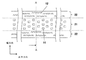
活物質2は図示せず、集電体1のみを表面から見た図が、図1である。集電体1は、図1の矢印で示すように、長手方向および幅方向を有する。集電体1の表面には、図1に示すように幅方向中央部に第1の突起11が形成された第1の領域21と、幅方向両端部に第2の突起12が形成された第2の領域22がある。
The
第1の領域21の幅は、電池の用途によって異なり、特に限定されない。たとえば、60〜65mmである。第2の領域22の幅は、製造上必要な幅であり、たとえば、0.25〜5mm、より好ましくは、0.5〜2.5mmである。また、第1の領域と第2の領域は幅方向に連続的に形成されていてもよいし、第1の領域と第2の領域の間に、たとえば突起のない領域などの間の領域(第3の領域)が存在してもよい。
The width | variety of the 1st area |
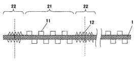
図2は、集電体1を図1のAA断面で切断した断面図である。分かりやすいように、集電体1のスリット前の状態、すなわち、幅方向に複数の集電体1が連続している状態で表示してある。
FIG. 2 is a cross-sectional view of the
図1及び図2より明らかなように、第1の領域21と、第2の領域22では、突起の形状、突起の配置が異なっている。第1の領域21では、突起11は比較的規則的に形成されているのに対して、第2の領域22では、突起12は比較的不規則(ランダム)に形成されている。
As is apparent from FIGS. 1 and 2, the
また、突起11,12は、通常、図2に示すように、集電体1の両表面に形成されるが、一面のみに形成されている場合も本発明は有効である。
In addition, the
集電体1は、銅、ニッケル、鉄から選ばれる少なくとも一つの元素を含む金属が好ましく、これらを主成分とした合金材料を用いることもできる。特にこの中でも屈曲性、延伸性に優れリチウムとの反応が無い、銅または銅合金が特に好ましい。例えば銅の場合は、電解銅箔、電解銅合金箔、さらにあらかじめ粗化処理を施した電解銅箔、粗化処理を施した圧延銅箔などが用いることができる。
The
集電体1の厚みとしては、任意の厚みを用いることができるが、5μm〜100μmが好ましく、特に8μm〜35μmが好ましい。これは、厚みが100μm以上の場合、集電体の強度は確保されるが、電池全体に占める集電体体積が大きくなり、電池の高容量化が期待できない。一方、5μmより薄いと、強度が確保できず、集電体に皺あるいは破断が発生するからである。
The thickness of the
次に、第1の突起11を規則的に配置形成する目的は、気相法等で活物質層を形成する際に、集電体の突起部分による陰影によって、活物質層に空間を設けることにある。集電体突起部分による陰影効果は、斜め蒸着に代表されるような、斜め入射の気相法で活物質層を形成する場合に、特に顕著に現れる。このように活物質層の空間割合を大きくすることでリチウム吸蔵時の活物質層膨張を吸収することができる。
Next, the purpose of regularly arranging and forming the
本発明の第1の突起11のパターン形状に特に制限はないが、凸部11は10〜20μm角が好ましく、凹部の幅は10μm程度が好ましい。したがって、第1の突起11の形成されている周期は、20〜30μmである。なお、この周期は、幅方向および長手方向で、同一であっても、異なっていてもよいが、両方とも、この範囲に収まっているのが望ましい。凹部の幅が広いと集電体突起部分による陰影効果がなくなり、凹部の幅が狭いと活物質粒子の空間割合が小さくなる。また、突起11の頭頂部が平坦で、断面形状は柱状、多角形、円柱、円錐、台形などが好ましい。このように突起の頭頂部を平坦にすることで活物質粒子は突起11を核にして垂直方向に柱状成長し、粒子が太く成長するのを抑制することができる。また、これらの形状を有するパターンはレジスト工法とメッキ工法の組合せで容易に作製することが出来る。
Although there is no restriction | limiting in particular in the pattern shape of the 1st processus |
集電体の表面突起部11の高さとしては、1〜20μmが好ましく、特に3〜10μmが好ましい。これは、突起高さが1μmより小さいと、応力緩和が不十分になる。突起高さが20μm以上の場合、電池全体に占める突起部体積が大きくなり、電池の高容量化が期待できないからである。
The height of the
しかしながらこれらを有する集電体上に形成された活物質層は、集電体界面との密着強度が弱く、衝撃などによって剥離しやすいという課題を有する。 However, the active material layer formed on the current collector having these has a problem that the adhesion strength with the current collector interface is weak and is easily peeled off by impact or the like.
これに対してランダムな突起を有する集電体は、活物質層と集電体界面の密着強度を大きくすることができる。本発明はこのように密着性の高い第2の領域22を集電体の幅方向の端部に設けることを特徴とし、走行系およびスリットによるダメージから活物質が集電体界面から剥離するのを抑制することができる。これにより、優れた充放電特性が得られる。
In contrast, a current collector having random protrusions can increase the adhesion strength between the active material layer and the current collector interface. The present invention is characterized in that the
第2の突起12がランダムに形成された第2の領域22の形成方法としては、ウェットエッチングにより容易に作製することが出来る。集電体に銅を用いる際のエッチャントとしては、希硫酸+過酸化水溶液等の酸を使用し、循環式のシャワー工程エッチングすることにより、Raが0.1〜1.0μm程度の突起を成型することが出来る。また第1の領域21をレジストで保護し、第2の領域22に粒径が数μm〜十数μm程度のアルミナやジルコニアなどのセラミック粉体を圧縮空気で吹き付けるサンドブラスト法等のドライエッチングによってもRaが0.5〜5μm程度の突起を成型することが出来る。
As a method of forming the
第2の領域22の集電体表面粗さRaが0.5μm未満の場合、活物質2との付着力が低下し剥離が発生しやすい。またRaを大きくするためには集電体1の厚みも大きくする必要があり、厚みが35μm以下の集電体においては、サンドブラスト法などによってRaを5μm以上に加工することは困難である。このためRaは0.5μm以上5μm以下であることが好ましい。このような表面粗さを設けることにより、集電体界面と活物質の密着強度を大きくすることができる。表面粗さRaは、日本工業規格(JISB 0601―1994)に定められており、例えば表面粗さ計等により測定することが出来る。
When the current collector surface roughness Ra of the
次に図3に前記集電体1上に活物質2を成膜した電極の断面の概略図を示す。
Next, FIG. 3 shows a schematic view of a cross section of an electrode in which an
薄膜を形成する際に突起を有する基板を使用する場合、突起凸部の先端部では蒸気圧が高く、突起の凹部では蒸気圧が低くなり基板表面上で蒸気圧分布が発生する。このため、突起を有する基板を使用する場合、突起の先端部分を核として柱状に成長しやすい。 When a substrate having a protrusion is used when forming a thin film, the vapor pressure is high at the tip of the protrusion and the vapor pressure is low at the protrusion, and a vapor pressure distribution is generated on the surface of the substrate. For this reason, when using the board | substrate which has a processus | protrusion, it tends to grow in columnar shape by using the front-end | tip part of a processus as a nucleus.
さらに本発明の実施の形態においては、集電体1の第1の領域21の突起11の陰影によって活物質層2に柱状成長した柱と柱の間に空間が生じ、この陰影効果は、斜め蒸着に代表されるような斜め入射の気相法で活物質層2を形成する際に、特に顕著に現れる。
Further, in the embodiment of the present invention, a space is generated between the pillars grown in the
このように活物質層内の空間割合を大きくすることでリチウム吸蔵時の活物質層膨張を吸収することができる。 Thus, by increasing the space ratio in the active material layer, it is possible to absorb the expansion of the active material layer during lithium storage.
集電体1の第2の領域22おいては、互いに隣接する突起凸部の間隔、凸部の高さ、谷間凹部の深さがランダムに配列して形成されており、突起凸部12の中心間距離(すなわち周期)は、0.1〜6μm、凸部の突起高さは、0.5〜20μm、表面粗さRaは、0.5〜5μmの範囲であることが好ましい。なお、周期は、幅方向および長手方向で、同一であっても、異なっていてもよいが、両方とも、この範囲に収まっているのが望ましい。このような表面形状であれば、活物質層2が成長する際に柱と柱の間の空間に分布が生じ、さらに第2の領域22のRaが0.5μmから5μmの範囲においては、突起と突起の間隔が柱の高さより十分に小さく、活物質層2が柱状成長する際にお互いに接触し阻害する。その為、柱状粒子が太く成長することが出来ない。
In the
このため集電体1の第2の領域22においては、第1の領域21にくらべて活物質層2の柱状粒子が密に成長し空間割合が少なくなる。これによって第2の領域22においては、集電体1と活物質法2の密着強度が高まり、剥離が抑制される。
Therefore, in the
以上、説明したように、第1の領域21の突起11が形成されている周期に比べて、第2の領域の突起の周期は、小さい。第1の領域21の突起11を集電体1の表面全域に形成すると、スリット時に課題があり、第2の領域22の突起12を表面全域に形成すると、活物質2の特性が確保できなくなる。したがって、第1、第2の領域に異なった周期の突起を形成する必要がある。
As described above, the period of the protrusions in the second region is smaller than the period in which the
本発明で用いる活物質は、リチウムイオンを吸蔵、放出するものであれば特に限定されないが、負極材料の場合にはケイ素、グルマニウム、錫単体或いはこれらの合金や、酸化ケイ素、窒化珪素、酸化錫等これらの酸化物、窒化物が、高エネルギー密度を得る上で好ましい。また、これらの材料群は、リチウムとの反応性と繰り返し充放電における耐久性が高いという観点から非晶質または低結晶性であることが好ましい。ここで、低結晶性とは、結晶粒の粒径が50nm以下の領域を言う。結晶粒の粒径は、X線回折分析で得られる回折像の中で最も強度の大きなピークの半価幅から、Scherrerの式によって算出される。また、非晶質とは、X線回折分析で得られる回折像において、2θ=15〜40°の範囲にブロードなピークを有することを言う。また、正極材料の場合には、LiCoO2、LiNiO2、LiMn2O4が高エネルギー密度を得る上で好ましい。これらの材料群では、リチウムとの反応性と繰り返し充放電における耐久性が高いという観点から結晶質であることが好ましい。 The active material used in the present invention is not particularly limited as long as it absorbs and releases lithium ions, but in the case of a negative electrode material, silicon, glutanium, tin alone or an alloy thereof, silicon oxide, silicon nitride, tin oxide These oxides and nitrides are preferable for obtaining a high energy density. In addition, these materials are preferably amorphous or low crystalline from the viewpoints of reactivity with lithium and high durability in repeated charge and discharge. Here, low crystallinity refers to a region where the crystal grain size is 50 nm or less. The grain size of the crystal grain is calculated by the Scherrer equation from the half-value width of the peak having the highest intensity in the diffraction image obtained by X-ray diffraction analysis. The term “amorphous” means that the diffraction image obtained by X-ray diffraction analysis has a broad peak in the range of 2θ = 15 to 40 °. In the case of a positive electrode material, LiCoO 2 , LiNiO 2 , and LiMn 2 O 4 are preferable for obtaining a high energy density. These materials are preferably crystalline from the viewpoints of reactivity with lithium and high durability in repeated charge and discharge.
次に、活物質層2を形成する方法について説明する。活物質層2を真空プロセスで形成する方法としては、蒸着法、スパッタ法、CVD法などを用いることが出来るが、中でも蒸着法が効率的に活物質層を形成する観点から特に望ましい。蒸着法は電子ビーム蒸着を用いても良く、抵抗加熱蒸着を行っても良い。シリコンや錫の酸化物や窒化物の蒸着を行う場合には、酸化物や窒化物を蒸発材料として用いてもよく、また、シリコンや錫を蒸発させながら酸素ガスや窒素ガス、またはこれらガスをイオン化あるいはラジカル化したものを差し向けることによって反応蒸着を行っても良い。
Next, a method for forming the
活物質層2の厚さは、必要な容量などにもよるが、通常は5μm〜40μmの範囲である。活物質層2が5μm未満になると、電池全体に占める活物質の割合が小さくなり、電池のエネルギー密度が低下する。また、活物質層2が40μmを超えると集電体と活物質層との界面における応力が大きくなり、本発明の構成を用いた場合でも集電体の変形などが発生する。
The thickness of the
図4は、蒸着法を用いた場合の本発明における極板の製造方法を示す模式図である。排気ポンプ3で排気されている真空槽4の中で、巻き出しロール5から巻き出された長尺の集電体1は搬送ローラ6及び円筒状のキャン7の周面に沿って走行し、巻き取りロール8に巻き取られる。その間に蒸発源9より活物質蒸気が供給され、マスク10の開口部を通過した蒸気により集電体1の表面に活物質層2が形成される。その後、巻き取りロール8により巻き取られることで活物質層2形成した集電体1を製造することが出来る。
FIG. 4 is a schematic diagram showing a method for producing an electrode plate according to the present invention when using a vapor deposition method. In the
次に、集電体を複数本に割断するスリット工程について図5を用いて説明する。 Next, the slit process which cleaves a collector into multiple pieces is demonstrated using FIG.
原反31である活物質層2を形成した集電体は、搬送ローラ32により送り出され、複数の刃を設けたスリット刃により所定の電極幅に切断される。従来においてはこのスリット工程の際に、電極端部では走行系との摩擦によるダメージを受け、衝撃により活物質が集電体から剥離するという大きな課題を有していた。
The current collector on which the
一方、本発明の実施の形態においては、電極端部を第2の突起12がランダムに形成された第2の領域22とすることで、活物質2との密着性が向上しスリット工程の際にも集電体からの剥離を抑制することが可能となる。この際、走行系との摩擦が発生する前記第2の領域22の幅は、走行の安定性を確保するため0.5mmから10mm、より好ましくは1mmから5mm程度であることが好ましい。
On the other hand, in the embodiment of the present invention, the electrode end portion is the
その後、スリット刃33により所定の電極幅に切り分けられた極板35は巻き取りロール34により巻き取られることで、一度の成膜工程で複数本分の極板35を製造することが可能となる。
Thereafter, the
所定の電極幅にスリットされた負極板は、セパレーターを介して正極と対向して捲回、または積層される。セパレーターとしてポリプロピレン製のセパレーター(セルガード社製、厚さ20μm)等を用いることが出来る。 The negative electrode plate slit to have a predetermined electrode width is wound or laminated so as to face the positive electrode through a separator. As the separator, a separator made of polypropylene (manufactured by Celgard, thickness 20 μm) or the like can be used.
正極板は、例えば厚さ15μmの圧延Al箔の集電体上に、活物質としてLiCoO2、LiNiO2、LiMn2O4などの粉体とアセチレンブラック(AB)とを、ポリフッ化ビニリデン(PVDF)等の有機バインダとともに混練したものを塗布・乾燥後、圧延したものを使用することが出来る。 The positive electrode plate is made of, for example, a powdered material such as LiCoO 2 , LiNiO 2 , LiMn 2 O 4 as active material and acetylene black (AB) on a current collector of a rolled Al foil having a thickness of 15 μm, and polyvinylidene fluoride (PVDF). ) And the like, and those that have been kneaded with an organic binder, applied and dried, and then rolled can be used.
その後、電解液の注液が行われ、図6に一例を示した捲回電池や、積層電池などを構成する。電池の構成は負極板を、エチレンカーボネートなどの環状カーボネート類とジメチルカーボネートなどの鎖状カーボネート類との混合溶媒に6フッ化リン酸リチウムなどを溶解した電解液を含んだセパレーターを介して正極板と対向させることで行われる。円筒型、扁平型、コイン型、角形等の様々な形状の電池が製造可能である。 Thereafter, the electrolytic solution is injected to form a wound battery, a laminated battery, or the like as shown in FIG. The structure of the battery is that the negative electrode plate is connected to the positive electrode plate via a separator containing an electrolytic solution in which lithium hexafluorophosphate is dissolved in a mixed solvent of cyclic carbonates such as ethylene carbonate and chain carbonates such as dimethyl carbonate. It is done by facing. Batteries having various shapes such as a cylindrical shape, a flat shape, a coin shape, and a square shape can be manufactured.
これら一連の工程によって、負極板の第1の領域21に形成された活物質層の空間は、充電時の負極板膨張時に必要な膨張空間として使用される。従って、負極活物質の応力緩和が可能となるため、正極負極間の短絡を抑制することができ、更に、集電体と活物質2の密着力の強い領域22でスリットすることによって、製造工程での活物質の剥離を抑制することが可能となり、歩留まりの高い電池を得ることができる。
Through these series of steps, the space of the active material layer formed in the
本発明は、薄膜工程により活物質を形成する際にスリット工程での活物質の剥離による歩留まりの低下を抑制する製造方法を提供するものである。本発明の製造方法により得られる極板は電池産業分野に限らず、電気化学素子全般への応用が可能である。 This invention provides the manufacturing method which suppresses the fall of the yield by peeling of the active material in a slit process, when forming an active material by a thin film process. The electrode plate obtained by the production method of the present invention is not limited to the battery industry field and can be applied to all electrochemical devices.
1 集電体
2 活物質
3 排気ポンプ
4 真空槽
5 巻き出しロール
6 搬送ローラ
7 キャン
8 巻き取りロール
9 蒸着源
10 マスク
11 第1の突起
12 第2の突起
21 第1の領域
22 第2の領域
30 スリット装置
31 原反
32 搬送ローラ
33 スリット刃
34 巻き取りロール
35 極板
41 正極
42 負極
43 正極リード
44 負極リード
45 上部絶縁リング
46 下部絶縁リング
47 電極間
48 封口板
49 絶縁パッキン
50 極板群
DESCRIPTION OF
Claims (8)
前記集電体は、突起部が規則的に形成された第1の領域と、突起部がランダムに形成された第2の領域を、同一面上に有することを特徴とするリチウム二次電池用電極。 An electrode carrying an active material capable of occluding and releasing lithium on a current collector,
The current collector has a first region in which protrusions are regularly formed and a second region in which protrusions are randomly formed on the same surface. electrode.
前記集電体は、突起部が規則的に形成された第1の領域と、突起部がランダムに形成された第2の領域とを、少なくとも一つの面に有し
前記第2の領域が形成された部分をスリットすることを特徴とするリチウム二次電池用電極の製造方法。 An electrode carrying an active material capable of occluding and releasing lithium on a current collector,
The current collector has, on at least one surface, a first region in which protrusions are regularly formed and a second region in which protrusions are randomly formed, and the second region is formed. A method for producing an electrode for a lithium secondary battery, comprising slitting the formed portion.
Priority Applications (1)
| Application Number | Priority Date | Filing Date | Title |
|---|---|---|---|
| JP2006285921A JP2008103231A (en) | 2006-10-20 | 2006-10-20 | Electrode for lithium secondary battery |
Applications Claiming Priority (1)
| Application Number | Priority Date | Filing Date | Title |
|---|---|---|---|
| JP2006285921A JP2008103231A (en) | 2006-10-20 | 2006-10-20 | Electrode for lithium secondary battery |
Publications (1)
| Publication Number | Publication Date |
|---|---|
| JP2008103231A true JP2008103231A (en) | 2008-05-01 |
Family
ID=39437400
Family Applications (1)
| Application Number | Title | Priority Date | Filing Date |
|---|---|---|---|
| JP2006285921A Pending JP2008103231A (en) | 2006-10-20 | 2006-10-20 | Electrode for lithium secondary battery |
Country Status (1)
| Country | Link |
|---|---|
| JP (1) | JP2008103231A (en) |
Cited By (4)
| Publication number | Priority date | Publication date | Assignee | Title |
|---|---|---|---|---|
| JP2008300255A (en) * | 2007-06-01 | 2008-12-11 | Panasonic Corp | Electrode for electrochemical element and electrochemical element using it |
| JP2011134564A (en) * | 2009-12-24 | 2011-07-07 | Toyota Motor Corp | Lithium-ion secondary battery, and vehicle and apparatus with the lithium-ion secondary battery thereon |
| JP2012216513A (en) * | 2011-03-29 | 2012-11-08 | Fujifilm Corp | Aluminum base material for collector, collector, positive electrode, negative electrode, and secondary battery |
| KR102050250B1 (en) * | 2015-09-09 | 2019-12-17 | 주식회사 엘지화학 | Electrode for Secondary Battery with Improved Production Processability |
-
2006
- 2006-10-20 JP JP2006285921A patent/JP2008103231A/en active Pending
Cited By (6)
| Publication number | Priority date | Publication date | Assignee | Title |
|---|---|---|---|---|
| JP2008300255A (en) * | 2007-06-01 | 2008-12-11 | Panasonic Corp | Electrode for electrochemical element and electrochemical element using it |
| WO2008149492A1 (en) * | 2007-06-01 | 2008-12-11 | Panasonic Corporation | Electrode for electrochemical element and electrochemical element using the electrode |
| US8257869B2 (en) | 2007-06-01 | 2012-09-04 | Panasonic Corporation | Electrode for electrochemical element and electrochemical element using the electrode |
| JP2011134564A (en) * | 2009-12-24 | 2011-07-07 | Toyota Motor Corp | Lithium-ion secondary battery, and vehicle and apparatus with the lithium-ion secondary battery thereon |
| JP2012216513A (en) * | 2011-03-29 | 2012-11-08 | Fujifilm Corp | Aluminum base material for collector, collector, positive electrode, negative electrode, and secondary battery |
| KR102050250B1 (en) * | 2015-09-09 | 2019-12-17 | 주식회사 엘지화학 | Electrode for Secondary Battery with Improved Production Processability |
Similar Documents
| Publication | Publication Date | Title |
|---|---|---|
| JP4445030B2 (en) | Current collector and manufacturing method thereof | |
| US10411253B2 (en) | Composite electrode material and method for manufacturing the same | |
| JP5210162B2 (en) | Anode for non-aqueous electrolyte secondary battery, method for producing the same, and non-aqueous electrolyte secondary battery | |
| JP4177885B2 (en) | Negative electrode for lithium secondary battery, lithium ion secondary battery and method for producing the same | |
| JP5043338B2 (en) | Lithium secondary battery | |
| US8888870B2 (en) | Lithium secondary battery | |
| JP4351732B2 (en) | ELECTRODE FOR LITHIUM SECONDARY BATTERY AND LITHIUM SECONDARY BATTERY HAVING THE SAME | |
| JP5169156B2 (en) | Electrodes for electrochemical devices | |
| KR101295927B1 (en) | Battery | |
| JP5189210B2 (en) | Anode for non-aqueous electrolyte secondary battery and non-aqueous electrolyte secondary battery | |
| KR101071485B1 (en) | Lithium Secondary Battery | |
| JP2008258154A (en) | Negative electrode for lithium secondary battery and manufacturing method thereof, as well as lithium secondary battery equipped with negative electrode for lithium secondary battery | |
| JP2008098157A (en) | Negative electrode for lithium ion secondary battery and lithium ion secondary battery using the negative electrode | |
| JP2012028062A (en) | Negative electrode for lithium ion secondary battery and method of manufacturing the same, and lithium ion secondary battery | |
| JP2006185830A (en) | Lithium secondary battery | |
| JP2008117785A (en) | Negative electrode for lithium secondary battery and its manufacturing method | |
| JP2008103231A (en) | Electrode for lithium secondary battery | |
| JP2010182620A (en) | Lithium-ion secondary battery | |
| JP2007323990A (en) | Negative electrode for lithium secondary battery, and lithium secondary battery including it | |
| JP2010287466A (en) | Nonaqueous electrolyte secondary battery | |
| JP5045085B2 (en) | Negative electrode for lithium secondary battery | |
| KR102172070B1 (en) | Patterning of Lithium metal and electrochemical device prepared thereby | |
| JP2008098038A (en) | Collector, pole plate for nonaqueous electrolyte secondary battery, and method for manufacturing nonaqueous electrolyte secondary battery using the same | |
| JP2008258139A (en) | Negative electrode for nonaqueous electrolyte secondary battery, its manufacturing method, and nonaqueous electrolyte secondary battery using it | |
| JP2011082008A (en) | Electrode for electrochemical element, method of manufacturing the same, and lithium ion battery |