JP2008093805A - Drill - Google Patents
Drill Download PDFInfo
- Publication number
- JP2008093805A JP2008093805A JP2006280765A JP2006280765A JP2008093805A JP 2008093805 A JP2008093805 A JP 2008093805A JP 2006280765 A JP2006280765 A JP 2006280765A JP 2006280765 A JP2006280765 A JP 2006280765A JP 2008093805 A JP2008093805 A JP 2008093805A
- Authority
- JP
- Japan
- Prior art keywords
- angle
- cutting
- thinning blade
- drill
- rake angle
- Prior art date
- Legal status (The legal status is an assumption and is not a legal conclusion. Google has not performed a legal analysis and makes no representation as to the accuracy of the status listed.)
- Pending
Links
Images


Classifications
-
- B—PERFORMING OPERATIONS; TRANSPORTING
- B23—MACHINE TOOLS; METAL-WORKING NOT OTHERWISE PROVIDED FOR
- B23B—TURNING; BORING
- B23B51/00—Tools for drilling machines
- B23B51/02—Twist drills
-
- B—PERFORMING OPERATIONS; TRANSPORTING
- B23—MACHINE TOOLS; METAL-WORKING NOT OTHERWISE PROVIDED FOR
- B23B—TURNING; BORING
- B23B2251/00—Details of tools for drilling machines
- B23B2251/18—Configuration of the drill point
-
- Y—GENERAL TAGGING OF NEW TECHNOLOGICAL DEVELOPMENTS; GENERAL TAGGING OF CROSS-SECTIONAL TECHNOLOGIES SPANNING OVER SEVERAL SECTIONS OF THE IPC; TECHNICAL SUBJECTS COVERED BY FORMER USPC CROSS-REFERENCE ART COLLECTIONS [XRACs] AND DIGESTS
- Y10—TECHNICAL SUBJECTS COVERED BY FORMER USPC
- Y10T—TECHNICAL SUBJECTS COVERED BY FORMER US CLASSIFICATION
- Y10T408/00—Cutting by use of rotating axially moving tool
- Y10T408/89—Tool or Tool with support
- Y10T408/909—Having peripherally spaced cutting edges
- Y10T408/9095—Having peripherally spaced cutting edges with axially extending relief channel
- Y10T408/9097—Spiral channel
Landscapes
- Engineering & Computer Science (AREA)
- Mechanical Engineering (AREA)
- Drilling Tools (AREA)
Abstract
Description
本発明は、ドリルに関し、特に、工具寿命の向上を図りつつも、切削加工時における切削抵抗の減少を図ることができるドリルに関するものである。 The present invention relates to a drill, and more particularly to a drill that can reduce cutting resistance during cutting while improving tool life.
従来より、ドリルには、切削加工時における切削抵抗の減少を図るため、例えば、特開2000−271811号公報に開示されるツイストドリルのように、その先端部にシンニングが設けられている。このツイストドリルによれば、シンニング5を設けることによってチゼルエッジ長さが短くなるので、切削加工時には、かかるツイストドリルの先端部と被加工物との接触面積が減り、その結果、切削抵抗が減少する。 Conventionally, in order to reduce cutting resistance at the time of cutting, a drill is conventionally provided with a thinning at the tip thereof as in a twist drill disclosed in Japanese Patent Application Laid-Open No. 2000-271811. According to this twist drill, since the chisel edge length is shortened by providing the thinning 5, at the time of cutting, the contact area between the tip of the twist drill and the workpiece is reduced, and as a result, the cutting resistance is reduced. .
ところで、上述したツイストドリルによれば、シンニング5を設けることによって形成されるシンニング刃6のすくい角αは、一般に、その角度が大きいほど切削抵抗を減少させることができる一方、角度が大きいと、シンニング刃6の強度が低下してチッピングを招き易くなる。 By the way, according to the twist drill described above, the rake angle α of the thinning blade 6 formed by providing the thinning 5 can generally reduce the cutting resistance as the angle increases. The strength of the thinning blade 6 is lowered, and chipping is easily caused.
そこで、かかるツイストドリルでは、シンニング刃6のすくい角αが+5°から+15°の範囲内の角度に設定され、工具寿命の向上が図られている。
しかしながら、上述したツイストドリルのように、工具寿命を考慮してシンニング刃6のすくい角αを設定した場合には、切削抵抗を十分に減少させることができず、工具寿命の向上と切削抵抗の減少とを両立させることが困難であるという問題点があった。 However, when the rake angle α of the thinning blade 6 is set in consideration of the tool life as in the twist drill described above, the cutting resistance cannot be sufficiently reduced, and the tool life is improved and the cutting resistance is reduced. There was a problem that it was difficult to achieve both reductions.
本発明は上述した問題点を解決するためになされたものであり、工具寿命の向上を図りつつも、切削加工時における切削抵抗の減少を図ることができるドリルを提供することを目的としている。 The present invention has been made to solve the above-described problems, and an object of the present invention is to provide a drill that can reduce cutting resistance during cutting while improving the tool life.
この目的を解決するために請求項1記載のドリルは、軸心回りに回転される円柱状のボデーと、そのボデーの先端部に形成される切れ刃と、前記ボデーの先端部にシンニングを設けることにより前記切れ刃に連接して前記ボデーの軸心側に形成されるシンニング刃とを備えるものであって、前記シンニング刃は、そのシンニング刃と前記ボデーの軸心とがなす角であるすくい角が前記ボデーの軸心側と前記切れ刃側とで変化すると共に、前記シンニング刃のすくい角は、前記切れ刃側のすくい角が前記ボデーの軸心側のすくい角よりも大きい正の角度に設定されている。
In order to solve this object, a drill according to
請求項2記載のドリルは、請求項1記載のドリルにおいて、前記シンニング刃は、前記ボデーの軸心側に位置すると共に前記ボデーの先端方向視において略直線状に形成される第1シンニング刃と、その第1シンニング刃よりも前記切れ刃側に位置すると共に前記ボデーの先端方向視において略直線状に形成される第2シンニング刃とを備え、その第2シンニング刃のすくい角は、前記第1シンニング刃のすくい角よりも大きい正の角度に設定されている。
The drill according to
請求項3記載のドリルは、請求項2記載のドリルにおいて、前記切れ刃のすくい面を構成すると共に前記ボデーの外周面に凹設される螺旋状の溝と、その溝の回転方向後方側の壁面と前記ボデーの外周面とが交差する稜線部に形成されるリーディングエッジとを備え、前記第2シンニング刃のすくい角は、前記ボデーの軸心と前記リーディングエッジとがなす角であるねじれ角の1/5倍以上かつ1/2倍以下の範囲内の角度に設定されている。 A drill according to a third aspect is the drill according to the second aspect, wherein a spiral groove that forms a rake face of the cutting edge and is recessed in an outer peripheral surface of the body, and a rear side in the rotational direction of the groove. A leading edge formed on a ridge line portion where the wall surface and the outer peripheral surface of the body intersect, and a rake angle of the second thinning blade is a twist angle formed by an axis of the body and the leading edge Is set to an angle in the range of 1/5 times or more and 1/2 times or less.
請求項4記載のドリルは、請求項1記載のドリルにおいて、前記シンニング刃は、前記ボデーの先端方向視において円弧状に形成されると共に、前記すくい角が前記ボデーの軸心側から前記切れ刃側に向かうにつれて変化すると共に、前記シンニング刃のすくい角は、前記切れ刃側のすくい角が前記ボデーの軸心側のすくい角よりも大きい正の角度に設定されている。
The drill according to
請求項5記載のドリルは、請求項4記載のドリルにおいて、前記切れ刃のすくい面を構成すると共に前記ボデーの外周面に凹設される螺旋状の溝と、その溝の回転方向後方側の壁面と前記ボデーの外周面とが交差する稜線部に形成されるリーディングエッジとを備え、前記シンニング刃のすくい角は、前記シンニング刃と前記切れ刃との連接部において、前記ボデーの軸心と前記リーディングエッジとがなす角であるねじれ角の1/5倍以上かつ1/2倍以下の範囲内の角度に設定されている。 A drill according to a fifth aspect is the drill according to the fourth aspect, wherein a spiral groove that forms a rake face of the cutting edge and is recessed in an outer peripheral surface of the body, and a rear side in a rotational direction of the groove. A leading edge formed at a ridge line portion where the wall surface and the outer peripheral surface of the body intersect, and the rake angle of the thinning blade is the connecting center between the thinning blade and the cutting blade and the axis of the body The angle is set within a range of 1/5 times or more and 1/2 times or less of a twist angle that is an angle formed by the leading edge.
請求項1記載のドリルによれば、シンニング刃は、すくい角がボデーの軸心側と切れ刃側とで変化すると共に、そのシンニング刃のすくい角は、切れ刃側のすくい角がボデーの軸心側のすくい角よりも大きい正の角度に設定されている。
According to the drill of
ここで、シンニング刃のすくい角は、一般に、その角度が大きいほど、被加工物への食い付き性を向上させることができ切削抵抗を減少させることができる一方、角度が大きいと、シンニング刃の強度が低下してチッピングを生じ易くなる。 Here, as for the rake angle of the thinning blade, in general, as the angle increases, the biting property to the workpiece can be improved and the cutting resistance can be reduced. The strength is reduced and chipping is likely to occur.
これに対し、本発明におけるドリルによれば、切削加工時において周速が遅く切削抵抗が大きいボデーの軸心側のすくい角を切れ刃側のすくい角よりも小さい角度に設定することで、切削抵抗に耐え得る強度をシンニング刃に持たせつつも、切れ刃側のすくい角をボデーの軸心側のすくい角よりも大きい角度に設定することで、切削加工が進行して所定の切り込み深さに達した後には、被加工物への食い付き性を向上させることができる。 On the other hand, according to the drill of the present invention, by setting the rake angle on the axis side of the body whose peripheral speed is slow and cutting resistance is large at the time of cutting, the cutting angle is set smaller than the rake angle on the cutting edge side. By setting the rake angle on the cutting edge side to a larger angle than the rake angle on the axis side of the body while giving the thinning blade strength to withstand resistance, the cutting process progresses and the predetermined cutting depth is reached. After reaching the above, the biting property to the workpiece can be improved.
よって、シンニング刃のチッピングを防止して工具寿命の向上を図りつつも、被加工物への食い付き性を向上させて切削加工時における切削抵抗の減少を図ることができるという効果がある。これにより、工具寿命の向上と切削抵抗の減少との両立を図ることができる。 Therefore, the chipping of the thinning blade is prevented and the tool life is improved, and the biting property to the workpiece is improved, and the cutting resistance at the time of cutting can be reduced. Thereby, coexistence with improvement of a tool life and reduction of cutting resistance can be aimed at.
請求項2記載のドリルによれば、請求項1記載のドリルの奏する効果に加え、シンニング刃は、ボデーの軸心側に位置する第1シンニング刃と、その第1シンニング刃よりも切れ刃側に位置する第2シンニング刃とを備え、その第2シンニング刃のすくい角が第1シンニング刃のすくい角よりも大きい正の角度に設定されているので、第1シンニング刃によって切削抵抗に耐え得る強度を持たせつつも、切削加工が進行して所定の切り込み深さに達した後には、第2シンニング刃によって被加工物への食い付き性を向上させることができる。
According to the drill of
よって、シンニング刃のチッピングを防止して工具寿命の向上を図りつつも、被加工物への食い付き性を向上させて切削加工時における切削抵抗の減少を図ることができるという効果がある。 Therefore, the chipping of the thinning blade is prevented and the tool life is improved, and the biting property to the workpiece is improved, and the cutting resistance at the time of cutting can be reduced.
また、シンニング刃をボデーの先端方向視において略直線状とした場合でも、第1シンニング刃と第2シンニング刃とを備えているので、ボデーの軸心側と切れ刃側とですくい角が変化するシンニング刃を容易に加工することができるという効果がある。 Even when the thinning blade is substantially straight when viewed from the front end of the body, the first thinning blade and the second thinning blade are provided, so the rake angle changes between the body axis and the cutting edge. The thinning blade can be easily processed.
請求項3記載のドリルによれば、請求項2記載のドリルの奏する効果に加え、第2シンニング刃のすくい角は、ねじれ角の1/5倍以上かつ1/2倍以下の範囲内の角度に設定されているので、加工精度の向上を図ることができると共に、工具寿命の向上を図ることができるという効果がある。
According to the drill of
即ち、すくい角がねじれ角の1/5倍より小さい場合には、切削加工時における切削抵抗が増大してドリルが振動を生じ易くなる。これに対し、すくい角をねじれ角の1/5以上とすることで、切削抵抗を減少させることができるので、ドリルの振動を防止でき、その結果、加工精度の向上を図ることができる。 That is, when the rake angle is smaller than 1/5 times the torsion angle, the cutting resistance at the time of cutting increases and the drill tends to vibrate. On the other hand, since the cutting resistance can be reduced by setting the rake angle to 1/5 or more of the helix angle, the vibration of the drill can be prevented, and as a result, the machining accuracy can be improved.
一方、すくい角がねじれ角の1/2倍より大きい場合には、第2シンニング刃の強度が低下してチッピングを生じ易くなる。これに対し、すくい角をねじれ角の1/2以上とすることで、第2シンニング刃の強度を高めることができるので、チッピングを防止でき、その結果、工具寿命の向上を図ることができる。 On the other hand, when the rake angle is larger than ½ times the torsion angle, the strength of the second thinning blade is lowered and chipping is likely to occur. On the other hand, since the strength of the second thinning blade can be increased by setting the rake angle to ½ or more of the helix angle, chipping can be prevented, and as a result, the tool life can be improved.
また、上述した第2シンニング刃のすくい角は、ねじれ角に比例して設定されているので、その第2シンニング刃のすくい角を被加工物の材質に合った最適なすくい角とすることができるという効果がある。即ち、ねじれ角は、一般に、被加工物の材質に合わせて設定されるため、すくい角をねじれ角に比例して設定することによって、例えば、ねじれ角が強ねじれに設定される硬質の被加工物に対しては、ねじれ角と同様にすくい角を大きく設定することができ、切削抵抗を減少させるべく硬質の被加工物の切削加工に最適なすくい角とすることができる。 In addition, since the rake angle of the second thinning blade described above is set in proportion to the twist angle, the rake angle of the second thinning blade is set to an optimum rake angle that matches the material of the workpiece. There is an effect that can be done. That is, the torsion angle is generally set in accordance with the material of the work piece. Therefore, by setting the rake angle in proportion to the torsion angle, for example, a hard work in which the torsion angle is set to a strong torsion. For an object, the rake angle can be set large similarly to the torsion angle, and the rake angle can be made optimum for cutting a hard workpiece so as to reduce the cutting resistance.
請求項4記載のドリルによれば、請求項1記載のドリルの奏する効果に加え、シンニング刃は、すくい角がボデーの軸心側から切れ刃側に向かうにつれて変化すると共に、そのシンニング刃のすくい角は、切れ刃側のすくい角がボデーの軸心側のすくい角よりも大きい正の角度に設定されているので、切削抵抗に耐え得る強度をシンニング刃に持たせつつも、切削加工が進行して所定の切り込み深さに達した後には、被加工物への食い付き性を向上させることができる。
According to the drill of
よって、シンニング刃のチッピングを防止して工具寿命の向上を図りつつも、被加工物への食い付き性を向上させて切削加工時における切削抵抗の減少を図ることができるという効果がある。 Therefore, the chipping of the thinning blade is prevented and the tool life is improved, and the biting property to the workpiece is improved, and the cutting resistance at the time of cutting can be reduced.
また、シンニング刃をボデーの先端方向視において円弧状としたので、そのシンニング刃のすくい角をボデーの軸心側から切れ刃側に向かうにつれて連続的に変化させることができる。よって、シンニング刃をボデーの先端方向視において略直線状とする場合と比較して、切削抵抗の減少を図ることができるという効果がある。 Further, since the thinning blade has an arc shape when viewed from the front end direction of the body, the rake angle of the thinning blade can be continuously changed from the axial center side of the body toward the cutting edge side. Therefore, there is an effect that the cutting resistance can be reduced as compared with the case where the thinning blade is substantially linear in the body tip direction view.
請求項5記載のドリルによれば、請求項4記載のドリルの奏する効果に加え、シンニング刃のすくい角は、シンニング刃と切れ刃との連接部において、ねじれ角の1/5倍以上かつ1/2倍以下の範囲内の角度に設定されているので、加工精度の向上を図ることができると共に、工具寿命の向上を図ることができるという効果がある。 According to the drill of the fifth aspect, in addition to the effect achieved by the drill according to the fourth aspect, the rake angle of the thinning blade is 1/5 times the torsion angle or more and 1 at the connecting portion between the thinning blade and the cutting edge. Since the angle is set within a range of less than or equal to 2 times, it is possible to improve the machining accuracy and to improve the tool life.
即ち、すくい角がねじれ角の1/5倍より小さい場合には、切削加工時における切削抵抗が増大してドリルが振動を生じ易くなる。これに対し、すくい角をねじれ角の1/5以上とすることで、切削抵抗を減少させることができるので、ドリルの振動を防止でき、その結果、加工精度の向上を図ることができる。 That is, when the rake angle is smaller than 1/5 times the torsion angle, the cutting resistance at the time of cutting increases and the drill tends to vibrate. On the other hand, since the cutting resistance can be reduced by setting the rake angle to 1/5 or more of the helix angle, the vibration of the drill can be prevented, and as a result, the machining accuracy can be improved.
一方、すくい角がねじれ角の1/2倍より大きい場合には、シンニング刃の強度が低下してチッピングを生じ易くなる。これに対し、すくい角をねじれ角の1/2以上とすることで、シンニング刃の強度を高めることができるので、チッピングを防止でき、その結果、工具寿命の向上を図ることができる。 On the other hand, when the rake angle is larger than ½ times the torsion angle, the strength of the thinning blade is lowered and chipping is likely to occur. On the other hand, since the strength of the thinning blade can be increased by setting the rake angle to ½ or more of the helix angle, chipping can be prevented, and as a result, the tool life can be improved.
また、上述したシンニング刃のすくい角は、シンニング刃と切れ刃との連接部における角度として設定されているので、切削加工時において周速が遅く切削抵抗が大きいボデーの軸心側のシンニング刃に対しては切削抵抗に耐え得る強度を持たせつつも、切削加工が進行して所定の切り込み深さに達した後には、被加工物への食い付き性を向上させることができるという効果がある。 In addition, since the rake angle of the thinning blade described above is set as an angle at the connecting portion between the thinning blade and the cutting edge, the thinning blade on the axial center side of the body has a low peripheral speed and high cutting resistance during the cutting process. On the other hand, there is an effect that the biting property to the workpiece can be improved after the cutting process proceeds and reaches a predetermined cutting depth while having a strength capable of withstanding the cutting resistance. .
更に、上述したシンニング刃と切れ刃との連接部におけるシンニング刃のすくい角は、ねじれ角に比例して設定されているので、そのシンニング刃のすくい角を被加工物の材質に合った最適なすくい角とすることができるという効果がある。即ち、ねじれ角は、一般に、被加工物の材質に合わせて設定されるため、すくい角をねじれ角に比例して設定することによって、例えば、ねじれ角が強ねじれに設定される硬質の被加工物に対しては、ねじれ角と同様にすくい角を大きく設定することができ、切削抵抗を減少させるべく硬質の被加工物の切削加工に最適なすくい角とすることができる。 Furthermore, since the rake angle of the thinning blade at the connecting portion between the thinning blade and the cutting blade is set in proportion to the torsion angle, the rake angle of the thinning blade is optimal for the material of the workpiece. There is an effect that a rake angle can be obtained. That is, the torsion angle is generally set in accordance with the material of the work piece. Therefore, by setting the rake angle in proportion to the torsion angle, for example, a hard work in which the torsion angle is set to a strong torsion. For an object, the rake angle can be set large similarly to the torsion angle, and the rake angle can be made optimum for cutting a hard workpiece so as to reduce the cutting resistance.
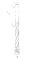
以下、本発明の好ましい実施の形態について、添付図面を参照して説明する。図1は、本発明の第1実施の形態におけるドリル1の側面図である。
DESCRIPTION OF EXEMPLARY EMBODIMENTS Hereinafter, preferred embodiments of the invention will be described with reference to the accompanying drawings. FIG. 1 is a side view of a
まず、図1を参照して、ドリル1の概略構成について説明する。ドリル1は、マシニングセンタ等の加工機械から伝達される回転力によって被加工物に穴あけ加工を行う切削工具であり、図1に示すように、タングステンカーバイト(WC)等を加圧焼結した超硬合金からソリッドドリルとして構成され、シャンク2と、そのシャンク2と一体成形されるボデー3とを主に備えて構成されている。
First, a schematic configuration of the
なお、本実施の形態では、ドリル1が超硬合金から構成されているが、必ずしもこれに限られるものではなく、例えば、高速度工具鋼から構成しても良い。
In the present embodiment, the
シャンク2は、加工機械に保持される部位であり、図1に示すように、ボデー3と略同径の円柱状に構成され、ボデー3と同一の軸心O上に設けられている。このシャンク2がホルダ(図示せず)に保持されることによって、ドリル1が加工機械に取り付けられる。
The
なお、本実施の形態では、シャンク2がボデー3と略同径の円柱状に構成されているが、必ずしもこれに限られるものではなく、例えば、ボデー3よりも大径に構成しても良く、或いは、ドリル1の端部側(図1上側)へ向けて縮径するテーパ状に構成しても良い。
In addition, in this Embodiment, although the
ボデー3は、シャンク2を介して加工機械から伝達される回転力によって回転しつつ切削加工を行うための部位であり、図1に示すように、被加工物(図示せず)に加工する穴と略同径の直径Dの円柱状に構成され、溝4と、切れ刃5とを主に備えている。なお、本実施の形態では、ドリル1の直径Dが6mmに構成されている。
The
溝4は、切れ刃5のすくい面を構成すると共に切削加工時に生成された切り屑の収容および排出を行うためのものであり、図1に示すように、ボデー3の外周面に2本の溝4が螺旋状にそれぞれ凹設され、それら2本の溝4がドリル1の軸心Oに対して対称に設けられている。
The
なお、本実施の形態では、溝4がねじれを伴う螺旋状に構成されているが、必ずしもこれに限られるものではなく、ドリル1の軸心Oと略平行の直線状に構成しても良い。
In the present embodiment, the
また、図1に示すように、ボデー3の外周面と溝4の回転方向(図2(a)の矢印A方向参照)後方側の壁面とが交差する稜線部には、リーディングエッジ6が形成されている。このリーディングエッジ6は、図1に示すように、ドリル1の軸心Oとなす角であるねじれ角βが38度に設定されている。
Further, as shown in FIG. 1, a leading edge 6 is formed at the ridge line portion where the outer peripheral surface of the
更に、図1に示すように、リーディングエッジ6の回転方向(図2(a)の矢印A方向参照)後方側には、そのリーディングエッジ6に連接してマージン7が設けられている。このマージン7は、被加工物に加工する穴の内壁面を研磨するためのものであり、ボデー3の外周面を除去して二番取り面8を設けることによって形成されている。
Further, as shown in FIG. 1, a
切れ刃5は、加工機械から伝達される回転力によって回転して被加工物を切削するためのものであり、図1に示すように、ドリル1の先端部と溝4とが交差する稜線部に2枚の切れ刃5がそれぞれ形成され、それら2枚の切れ刃5がドリル1の軸心Oに対して対称に設けられている。また、この切れ刃5は、ドリル1の先端方向視において略直線状にそれぞれ形成され、2枚の切れ刃5が平行に設けられている(図2参照)。
The
次に、図2を参照して、ボデー3の先端部の詳細構成について説明する。図2(a)は、図1の矢印II方向視におけるドリル1の正面図であり、図2(b)は、図2(a)のIIb−IIb線におけるドリル1の拡大断面図であり、図2(c)は、図2(a)のIIc−IIc線におけるドリル1の拡大断面図である。なお、図2(a)の矢印Aは、ドリル1の回転方向を示している。
Next, with reference to FIG. 2, the detailed structure of the front-end | tip part of the
図2(a)に示すように、ドリル1の先端部には、逃げ面9と、シンニング10とが主に設けられている。逃げ面9は、切削加工時におけるドリル1の先端部と被加工物との接触面積を減らして切削抵抗を減少させるためのものであり、図2(a)に示すように、ドリル1の先端部を除去して形成されると共に、切れ刃5の回転方向A後方側に連接して設けられている。これにより、切削加工時には、ドリル1と被加工物との間に隙間が生じるので、ドリル1と被加工物との摩擦が低減して切削抵抗が減少する。
As shown in FIG. 2A, a
なお、本実施の形態では、図2(a)に示すように、2枚の切れ刃5に対応して2つの逃げ面9がそれぞれ凹設され、それら2つの逃げ面9がドリル1の軸心Oに対して対称に設けられている。
In the present embodiment, as shown in FIG. 2A, two
ここで、上述したようにドリル1の先端部に逃げ面9を設けた場合でも、2つの逃げ面9が交差する稜線、いわゆるチゼルエッジ11の長さは依然長いままであり、切削加工時には、ドリル1の先端部と被加工物との接触面積が大きくなるので、十分に切削抵抗を減少させることができない。そこで、図2(a)に示すように、逃げ面9の回転方向A後方側には、その逃げ面9に連接してシンニング10が溝4と交差するまで延設されている。
Here, even when the
シンニング10は、逃げ面9と組み合わされて切削抵抗を相乗的に減少させるためのものであり、図2(a)に示すように、ドリル1の先端部を逃げ面9よりも更に除去して形成されている。これにより、チゼルエッジ11の長さが短くなり、切削加工時には、ドリル1の先端部と被加工物との接触面積が減るので、その結果、切削抵抗が減少する。
The thinning 10 is combined with the
なお、本実施の形態では、図2(a)に示すように、2つの逃げ面9に対応して2つのシンニング10がそれぞれ凹設され、それら2つのシンニング10がドリル1の軸心Oに対して対称に設けられている。また、図2(a)に示すように、逃げ面9とシンニング10とが交差する稜線間の寸法である入り組み寸法Xが0.4mmに設定されている。
In the present embodiment, as shown in FIG. 2 (a), two
また、ドリル1の先端部にシンニング10を設けることによって、そのドリル1の先端部には、図2(a)に示すように、切れ刃5に連接してシンニング刃12が形成されている。シンニング刃12は、切れ刃5と同様に加工機械から伝達される回転力によって回転して被加工物を切削するためのものであり、図2(a)に示すように、2つのシンニング10に対応して2枚のシンニング刃12がそれぞれ形成され、それら2枚のシンニング刃12がドリル1の軸心Oに対して対称に設けられている。
Further, by providing the thinning 10 at the tip of the
また、このシンニング刃12は、図2(a)に示すように、ドリル1の軸心O側に位置する第1シンニング刃12aと、その第1シンニング刃12aよりも切れ刃5側に位置する第2シンニング刃12bとを備えて構成されている。
Further, as shown in FIG. 2A, the thinning
第1シンニング刃12aは、被加工物に加工する穴の中心部を切削するためのものであり、図2(a)に示すように、ドリル1の先端方向視において略直線状に形成され、連接する切れ刃5となす中心角α1が53度に設定されている。なお、本実施の形態では、中心角α1が53度に設定されているが、必ずしもこれに限られるものではなく、50度以上かつ55度以下の範囲内に設定することが望ましい。
The
即ち、中心角α1が50度より小さい場合には、被加工物への食い付き性が低下してドリル1が振動を生じ易くなる。これに対し中心角α1を50度以上とすることで、被加工物への食い付き性を向上させることができるので、ドリル1の振動を防止でき、その結果、加工精度の向上を図ることができる。
That is, when the center angle α1 is smaller than 50 degrees, the biting property to the workpiece is lowered, and the
一方、中心角α1が55度より大きい場合には、逃げ面9との隙間が減少して切り屑排出性が低下する。これに対し中心角α1を55度以下とすることで、切り屑排出性を向上させることができるので、第1シンニング刃12aのチッピングを防止でき、その結果、工具寿命の向上を図ることができる。
On the other hand, when the central angle α1 is larger than 55 degrees, the gap with the
また、この第1シンニング刃12aは、図2(b)に示すように、ドリル1の軸心Oとなす角であるすくい角γ1が0度に設定されている。なお、本実施の形態では、すくい角γ1が0度に設定されているが、必ずしもこれに限られるものではなく、−5度以上かつ5度以下の範囲内に設定することが望ましい。
Further, as shown in FIG. 2B, the first thinning
即ち、すくい角γ1が−5度より小さい場合には、切削加工時における切削抵抗が増大してドリル1が振動を生じ易くなる。これに対し、すくい角γ1を−5度以上とすることで、切削抵抗を減少させることができるので、ドリル1の振動を防止でき、その結果、加工精度の向上を図ることができる。
That is, when the rake angle γ1 is smaller than −5 degrees, the cutting resistance at the time of cutting increases and the
一方、すくい角γ1が5度より大きい場合には、第1シンニング刃12aの強度が低下してチッピングを生じ易くなる。これに対し、すくい角γ1を5度以下とすることで、第1シンニング刃12aの強度を高めることができるので、チッピングを防止でき、その結果、工具寿命の向上を図ることができる。
On the other hand, when the rake angle γ1 is larger than 5 degrees, the strength of the first thinning
なお、本実施の形態では、図2(a)に示すように、2枚の第1シンニング刃12a間の最短寸法である切れ刃間隔Yが0.2mmに設定されている。
In the present embodiment, as shown in FIG. 2A, the cutting edge interval Y, which is the shortest dimension between the two
第2シンニング刃12bは、第1シンニング刃12aよりもドリル1の外周側、即ち、切れ刃5側に位置し、第1シンニング刃12aによって被加工物に加工する穴の中心部よりも外周部を切削するためのものであり、図2(a)に示すように、ドリル1の先端方向視において略直線状に形成され、連接する切れ刃5となす中心角α2が27度に設定されている。なお、本実施の形態では、中心角α2が27度に設定されているが、必ずしもこれに限られるものではなく、25度以上かつ30度以下の範囲内に設定することが望ましい。
The
即ち、中心角α2が25度より小さい場合には、被加工物への食い付き性が低下してドリル1が振動を生じ易くなる。これに対し中心角α2を25度以上とすることで、被加工物への食い付き性を向上させることができるので、ドリル1の振動を防止でき、その結果、加工精度の向上を図ることができる。
That is, when the central angle α2 is smaller than 25 degrees, the biting property to the workpiece is lowered, and the
一方、中心角α2が30度より大きい場合には、逃げ面9との隙間が減少して切り屑排出性が低下する。これに対し中心角α2を30度以下とすることで、切り屑排出性を向上させることができるので、第2シンニング刃12bのチッピングを防止でき、その結果、工具寿命の向上を図ることができる。
On the other hand, when the central angle α2 is larger than 30 degrees, the gap with the
また、この第2シンニング刃12bは、図2(c)に示すように、ドリル1の軸心Oとのなす角であるすくい角γ2が15度に設定されている。なお、本実施の形態では、すくい角γ2が15度に設定されているが、必ずしもこれに限られるものではなく、上述したねじれ角βの1/5倍以上かつ1/2倍以下の範囲内に設定することが望ましい。
Further, as shown in FIG. 2C, the
即ち、すくい角γ2がねじれ角βの1/5倍より小さい場合には、切削加工時における切削抵抗が増大してドリル1が振動を生じ易くなる。これに対し、すくい角γ2をねじれ角βの1/5以上とすることで、切削抵抗を減少させることができるので、ドリル1の振動を防止でき、その結果、加工精度の向上を図ることができる。
That is, when the rake angle γ2 is smaller than 1/5 times the torsion angle β, the cutting resistance at the time of cutting increases and the
一方、すくい角γ2がねじれ角βの1/2倍より大きい場合には、第2シンニング刃12bの強度が低下してチッピングを生じ易くなる。これに対し、すくい角γ2をねじれ角βの1/2以上とすることで、第2シンニング刃12bの強度を高めることができるので、チッピングを防止でき、その結果、工具寿命の向上を図ることができる。
On the other hand, when the rake angle γ2 is larger than ½ times the torsion angle β, the strength of the
また、上述した第2シンニング刃12bのすくい角γ2は、ねじれ角βに比例して設定されているので、その第2シンニング刃12bのすくい角γ2を被加工物の材質に合った最適なすくい角とすることができる。即ち、ねじれ角βは、一般に、被加工物の材質に合わせて設定されるため、すくい角γ2をねじれ角βに比例して設定することによって、例えば、ねじれ角βが強ねじれに設定される硬質の被加工物に対しては、ねじれ角βと同様にすくい角γ2を大きく設定することができ、切削抵抗を減少させるべく硬質の被加工物の切削加工に最適なすくい角とすることができる。
Further, since the rake angle γ2 of the
なお、第2シンニング刃12bのすくい角γ2は、特に、ねじれ角βの1/3倍以上かつ1/2倍以下の範囲内に設定することによって、より一層、被加工物の材質に合った最適なすくい角とすることができる。
In addition, the rake angle γ2 of the
更に、第2シンニング刃12bは、図2(a)に示すように、ドリル1の先端方向視において第1シンニング刃12aと連接する連接部Pがドリル1の軸心Oを中心とした直径1.85mmの円上に位置している。なお、本実施の形態では、連接部Pがドリル1の軸心Oを中心とした直径1.85mmの円上に位置しているが、必ずしもこれに限られるものではなく、ドリル1の外径Dの1/4倍以上かつ1/3倍以下の範囲内の円上に位置することが望ましい。
Further, as shown in FIG. 2A, the second thinning
即ち、連接部Pがドリル1の外径Dの1/4倍より小さい円上に位置する場合には、第1シンニング刃12aの範囲が狭くなり第2シンニング刃12bにチッピングを生じやすくなる。これに対し、連接部Pの位置をドリル1の外径Dの1/4倍以上の円上とすることで、第1シンニング刃12aの範囲を広くできるので、第2シンニング刃12bのチッピングを防止でき、その結果、工具寿命の向上を図ることができる。
That is, when the connecting portion P is located on a circle smaller than 1/4 of the outer diameter D of the
一方、連接部Pがドリル1の外径Dの1/3倍より大きい円上に位置する場合には、第2シンニング刃12bの範囲が狭くなり切削抵抗が増大する。これに対し、連接部Pの位置をドリル1の外径Dの1/3倍以下の円上とすることで、第2シンニング刃12bの範囲を広くできるので、切削抵抗を減少させることができ、その結果、加工精度の向上を図ることができる。
On the other hand, when the connecting portion P is located on a circle larger than 1/3 times the outer diameter D of the
なお、請求項2及び請求項4に記載のボデーの先端方向視とは、図1の矢印II方向視が該当する。
Note that the view of the body in the tip direction according to
次に、上述のように構成されるドリル1を用いて行った切削試験について説明する。切削試験は、ドリル1によって所定の切削条件で被加工物に穴あけ加工を行うことにより、切削加工時にドリル1が受ける切削抵抗の軸心O方向(図1左右方向)の分力、いわゆるスラスト抵抗を測定すると共に、ドリル1の外周コーナ摩耗量を測定する試験である。
Next, a cutting test performed using the
なお、切削試験の詳細諸元は、被加工物:JIS−S50C、使用機械:横型マシニングセンタ、切削油剤:水溶性切削油剤、切削速度:22m/min、送り速度:140mm/min、加工深さ:100mm(止まり穴)、ステップ送り:20mm→30mm→30mm→20mmである。 Detailed specifications of the cutting test are as follows: Workpiece: JIS-S50C, Machine used: Horizontal machining center, Cutting fluid: Water-soluble cutting fluid, Cutting speed: 22 m / min, Feed rate: 140 mm / min, Processing depth: 100 mm (blind hole), step feed: 20 mm → 30 mm → 30 mm → 20 mm.
また、切削試験には、本実施の形態で説明したドリル1(以下、「本発明品」と称す。)と、シンニング刃のすくい角がボデーの軸心側から切れ刃側にかけて一定に設定されているドリル(以下、「従来品」と称す。)とを用いて行った。但し、本発明品と従来品とは、シンニング刃の構成のみが異なり、他の構成については同一構成とされている。なお、従来品のシンニング刃は、ドリルの先端方向視において略直線状に形成され、連接する切れ刃となす中心角が55度に設定されると共に、ドリルの軸心となす角であるすくい角が0度に設定されている。
In the cutting test, the rake angle of the
ここで、図3を参照して、切削試験の試験結果について説明する。図3は、切削試験の試験結果を示すグラフであり、図3(a)は、本発明品でのスラスト抵抗を、図3(b)は、従来品でのスラスト抵抗を、図3(c)は、本発明品および従来品の外周コーナ摩耗量を、それぞれ示すグラフである。なお、図3(c)では、加工した穴の個数に対する外周コーナの摩耗量を示している。 Here, the test results of the cutting test will be described with reference to FIG. FIG. 3 is a graph showing the test results of the cutting test. FIG. 3A shows the thrust resistance in the product of the present invention, FIG. 3B shows the thrust resistance in the conventional product, and FIG. ) Is a graph showing the outer peripheral corner wear amount of the product of the present invention and the conventional product. FIG. 3C shows the amount of wear at the outer peripheral corner with respect to the number of holes processed.
切削試験の試験結果によれば、図3(a)及び図3(b)に示すように、本発明品は、従来品に対し、スラスト抵抗を減少させることができたことを容易に理解できる。具体的には、本発明品でのスラスト抵抗の平均値は876Nであったのに対し、従来品でのスラスト抵抗の平均値は1155Nであった。 According to the test results of the cutting test, as shown in FIGS. 3A and 3B, it can be easily understood that the product of the present invention was able to reduce the thrust resistance compared to the conventional product. . Specifically, the average value of the thrust resistance in the product of the present invention was 876N, while the average value of the thrust resistance in the conventional product was 1155N.
また、図3(c)に示すように、本発明品は、従来品に対し、外周コーナ摩耗量を低減させることができたことを容易に理解できる。具体的には、本発明品での外周コーナ摩耗量は、加工穴数が300個に達した時点でも0.23mmであったのに対し、従来品での外周コーナ摩耗量は、加工穴数が210個に達した時点で0.35mmであった。 Moreover, as shown in FIG.3 (c), it can understand easily that this invention product was able to reduce the amount of outer periphery corner abrasion with respect to the conventional product. Specifically, the peripheral corner wear amount in the product of the present invention was 0.23 mm even when the number of processed holes reached 300, whereas the peripheral corner wear amount in the conventional product was the number of processed holes. When the number reached 210, it was 0.35 mm.
上述したように、本実施の形態におけるドリル1によれば、シンニング刃12は、すくい角がボデー3の軸心O側と切れ刃5側とで変化すると共に、そのシンニング刃12のすくい角は、切れ刃5側のすくい角がボデー3の軸心O側のすくい角よりも大きい正の角度に設定されている。
As described above, according to the
ここで、シンニング刃12のすくい角は、一般に、その角度が大きいほど、被加工物への食い付き性を向上させることができ切削抵抗を減少させることができる一方、角度が大きいと、シンニング刃12の強度が低下してチッピングを生じ易くなる。
Here, as for the rake angle of the thinning
これに対し、本実施の形態におけるドリル1によれば、切削加工時において周速が遅く切削抵抗が大きいボデー3の軸心O側のすくい角を切れ刃5側のすくい角よりも小さい角度に設定することで、切削抵抗に耐え得る強度をシンニング刃12に持たせつつも、切れ刃5側のすくい角をボデー3の軸心O側のすくい角よりも大きい角度に設定することで、切削加工が進行して所定の切り込み深さに達した後には、被加工物への食い付き性を向上させることができる。
On the other hand, according to the
よって、シンニング刃12のチッピングを防止して工具寿命の向上を図りつつも、被加工物への食い付き性を向上させて切削加工時における切削抵抗の減少を図ることができる。これにより、工具寿命の向上と切削抵抗の減少との両立を図ることができる。
Therefore, chipping of the thinning
また、本実施の形態におけるドリル1では、シンニング刃12は、ボデー3の軸心O側に位置する第1シンニング刃12aと、その第1シンニング刃12aよりも切れ刃5側に位置する第2シンニング刃12bとを備え、その第2シンニング刃12bのすくい角γ2が第1シンニング刃12aのすくい角γ1よりも大きい正の角度に設定されているので、第1シンニング刃12aによって切削抵抗に耐え得る強度を持たせつつも、切削加工が進行して所定の切り込み深さに達した後には、第2シンニング刃12bによって被加工物への食い付き性を向上させることができる。
Moreover, in the
よって、シンニング刃12のチッピングを防止して工具寿命の向上を図りつつも、被加工物への食い付き性を向上させて切削加工時における切削抵抗の減少を図ることができる。
Therefore, chipping of the thinning
また、シンニング刃12をボデー3の先端方向視において略直線状とした場合でも、第1シンニング刃12aと第2シンニング刃12bとを備えているので、ボデー3の軸心O側と切れ刃5側とですくい角が変化するシンニング刃12を容易に加工することができる。
Even when the thinning
次に、図4を参照して、第2実施の形態におけるドリル101について説明する。図4(a)は、本発明の第2実施の形態におけるドリル101の正面図であり、図4(b)は、図4(a)のIVb−IVb線におけるドリル101の拡大断面図である。なお、第2実施の形態において第1実施の形態と同一の部分については、同一の符号を付してその説明及び図示を省略する。
Next, with reference to FIG. 4, the
第1実施の形態におけるドリル1では、シンニング刃12が第1シンニング刃12aと第2シンニング刃12bとを備え、それら第1シンニング刃12a及び第2シンニング刃12bがドリル1の先端方向視においてそれぞれ略直線状に形成される場合を説明したが、第2実施の形態におけるドリル101は、図4に示すように、シンニング刃112がドリル101の先端方向視において円弧状に形成されている。
In the
シンニング刃112は、切れ刃5と同様に加工機械から伝達される回転力によって回転して被加工物を切削するためのものであり、図4(a)に示すように、2つの逃げ面9に対応して2枚のシンニング刃112がそれぞれ凹設され、それら2枚のシンニング刃112がドリル101の軸心Oに対して対称に設けられている。
The thinning
また、このシンニング刃112は、図4(a)に示すように、ドリル101の先端方向視において円弧状に形成されている。更に、ドリル101の軸心Oとなす角であるすくい角が軸心Oから切れ刃5に向かうにつれて変化するように、切れ刃5側のすくい角が軸心O側のすくい角よりも大きい正の角度に設定され、図4(b)に示すように、切れ刃5と連接する連接部Qにおけるすくい角γ3が15度に設定されている。
Further, as shown in FIG. 4A, the thinning
なお、本実施の形態では、すくい角γ3が15度に設定されているが、必ずしもこれに限られるものではなく、ねじれ角βの1/5倍以上かつ1/2倍以下の範囲内に設定することが望ましい。 In the present embodiment, the rake angle γ3 is set to 15 degrees, but the rake angle γ3 is not necessarily limited to this, and is set within a range of 1/5 times or more and 1/2 times or less of the twist angle β. It is desirable to do.
即ち、すくい角γ3がねじれ角βの1/5倍より小さい場合には、切削加工時における切削抵抗が増大してドリル1が振動を生じ易くなる。これに対し、すくい角γ3をねじれ角βの1/5以上とすることで、切削抵抗を減少させることができるので、ドリル101の振動を防止でき、その結果、加工精度の向上を図ることができる。
That is, when the rake angle γ3 is smaller than 1/5 times the torsion angle β, the cutting resistance at the time of cutting increases and the
一方、すくい角γ3がねじれ角βの1/2倍より大きい場合には、シンニング刃112の強度が低下してチッピングを生じ易くなる。これに対し、すくい角γ3をねじれ角βの1/2以上とすることで、シンニング刃112の強度を高めることができるので、チッピングを防止でき、その結果、工具寿命の向上を図ることができる。
On the other hand, when the rake angle γ3 is larger than ½ times the torsion angle β, the strength of the thinning
また、上述したシンニング刃112のすくい角γ3は、シンニング刃112と切れ刃5との連接部Qにおける角度として設定されているので、切削加工時において周速が遅く切削抵抗が大きいボデー3の軸心O側のシンニング刃112に対しては切削抵抗に耐え得る強度を持たせつつも、切削加工が進行して所定の切り込み深さに達した後には、被加工物への食い付き性を向上させることができる。
Further, the rake angle γ3 of the thinning
更に、上述したシンニング刃112と切れ刃5との連接部Qにおけるシンニング刃112のすくい角γ3は、ねじれ角βに比例して設定されているので、そのシンニング刃112のすくい角γ3を被加工物の材質に合った最適なすくい角とすることができる。即ち、ねじれ角βは、一般に、被加工物の材質に合わせて設定されるため、すくい角γ3をねじれ角βに比例して設定することによって、例えば、ねじれ角βが強ねじれに設定される硬質の被加工物に対しては、ねじれ角βと同様にすくい角γ3を大きく設定することができ、切削抵抗を減少させるべく硬質の被加工物の切削加工に最適なすくい角とすることができる。
Furthermore, since the rake angle γ3 of the thinning
なお、連接部Qにおけるシンニング刃112のすくい角γ3は、特に、ねじれ角βの1/3倍以上かつ1/2倍以下の範囲内に設定することによって、より一層、被加工物の材質に合った最適なすくい角とすることができる。
Note that the rake angle γ3 of the thinning
上述したように、本実施の形態におけるドリル101によれば、シンニング刃112は、すくい角がボデー3の軸心O側から切れ刃5側に向かうにつれて変化すると共に、そのシンニング刃112のすくい角は、切れ刃5側のすくい角がボデー3の軸心O側のすくい角よりも大きい正の角度に設定されているので、切削抵抗に耐え得る強度をシンニング刃112に持たせつつも、切削加工が進行して所定の切り込み深さに達した後には、被加工物への食い付き性を向上させることができる。
As described above, according to the
よって、シンニング刃112のチッピングを防止して工具寿命の向上を図りつつも、被加工物への食い付き性を向上させて切削加工時における切削抵抗の減少を図ることができる。
Therefore, chipping of the thinning
また、シンニング刃112をボデー3の先端方向視において円弧状としたので、そのシンニング刃112のすくい角をボデー3の軸心O側から切れ刃5側に向かうにつれて連続的に変化させることができる。よって、シンニング刃112をボデー3の先端方向視において略直線状とする場合と比較して、切削抵抗の減少を図ることができる。
Further, since the thinning
以上、実施の形態に基づき本発明を説明したが、本発明は上記実施の形態に何ら限定される物ではなく、本発明の趣旨を逸脱しない範囲内で種々の改良変形が可能であることは容易に推察できるものである。 The present invention has been described above based on the embodiments, but the present invention is not limited to the above embodiments, and various improvements and modifications can be made without departing from the spirit of the present invention. It can be easily guessed.
例えば、上記各実施の形態で挙げた数値は一例であり、他の数値を採用することは当然可能である。 For example, the numerical values given in the above embodiments are merely examples, and other numerical values can naturally be adopted.
また、上記各実施の形態では、ドリル1,101が2枚の切れ刃5を備える2枚刃として構成される場合を説明したが、必ずしもこれに限定されるものではなく、例えば、3枚刃、或いは、4枚刃以上として構成しても良い。
Moreover, although the said each embodiment demonstrated the case where the
また、上記第1実施の形態では、シンニング刃12が第1シンニング刃12aと第2シンニング刃12bとを備える場合を説明したが、必ずしもこれに限られるものではなく、例えば、第2シンニング刃12bに連接し、その第2シンニング刃12bよりも切れ刃5側に位置する第3シンニング刃を備えて構成しても良い。この場合には、第3シンニング刃のすくい角を第2シンニング刃12bのすくい角γ2よりも大きく設定することによって、工具寿命の向上を図りつつも、切削加工時における切削抵抗の減少を図ることができる。
Moreover, although the said 1st Embodiment demonstrated the case where the thinning
1,101 ドリル
3 ボデー
4 溝
5 切れ刃
10 シンニング
12,112 シンニング刃
12a 第1シンニング刃(シンニング刃の一部)
12b 第2シンニング刃(シンニング刃の一部)
O 軸心
Q 連接部
β ねじれ角
γ1 すくい角(第1シンニング刃のすくい角)
γ2 すくい角(第2シンニング刃のすくい角)
γ3 すくい角
1,101
12b Second thinning blade (part of thinning blade)
O Shaft center Q Joint β β Helix angle γ1 Rake angle (rake angle of the first thinning blade)
γ2 rake angle (rake angle of second thinning blade)
γ3 rake angle
Claims (5)
前記シンニング刃は、そのシンニング刃と前記ボデーの軸心とがなす角であるすくい角が前記ボデーの軸心側と前記切れ刃側とで変化すると共に、前記シンニング刃のすくい角は、前記切れ刃側のすくい角が前記ボデーの軸心側のすくい角よりも大きい正の角度に設定されていることを特徴とするドリル。 A cylindrical body rotated around the axis, a cutting edge formed at the tip of the body, and a thinning at the tip of the body to connect the cutting edge to the axis side of the body In a drill comprising a thinning blade formed on,
In the thinning blade, a rake angle that is an angle formed by the thinning blade and the axis of the body changes between the axis side of the body and the cutting edge side, and the rake angle of the thinning blade is determined by the cutting edge. The drill characterized in that the rake angle on the blade side is set to a positive angle larger than the rake angle on the axial center side of the body.
その第2シンニング刃のすくい角は、前記第1シンニング刃のすくい角よりも大きい正の角度に設定されていることを特徴とする請求項1記載のドリル。 The thinning blade is located on the axial center side of the body and is formed in a substantially straight shape when viewed from the front end direction of the body, and is located closer to the cutting blade than the first thinning blade. A second thinning blade formed in a substantially linear shape when viewed from the front end direction of the body,
2. The drill according to claim 1, wherein a rake angle of the second thinning blade is set to a positive angle larger than a rake angle of the first thinning blade.
その溝の回転方向後方側の壁面と前記ボデーの外周面とが交差する稜線部に形成されるリーディングエッジとを備え、
前記第2シンニング刃のすくい角は、前記ボデーの軸心と前記リーディングエッジとがなす角であるねじれ角の1/5倍以上かつ1/2倍以下の範囲内の角度に設定されていることを特徴とする請求項2に記載のドリル。 A spiral groove that constitutes the rake face of the cutting edge and is recessed in the outer peripheral surface of the body;
A leading edge formed at a ridge line portion where the wall surface on the rear side in the rotation direction of the groove and the outer peripheral surface of the body intersect,
The rake angle of the second thinning blade is set to an angle that is not less than 1/5 times and not more than 1/2 times the torsion angle that is an angle formed by the axis of the body and the leading edge. The drill according to claim 2.
その溝の回転方向後方側の壁面と前記ボデーの外周面とが交差する稜線部に形成されるリーディングエッジとを備え、
前記シンニング刃のすくい角は、前記シンニング刃と前記切れ刃との連接部において、前記ボデーの軸心と前記リーディングエッジとがなす角であるねじれ角の1/5倍以上かつ1/2倍以下の範囲内の角度に設定されていることを特徴とする請求項4に記載のドリル。 A spiral groove that constitutes the rake face of the cutting edge and is recessed in the outer peripheral surface of the body;
A leading edge formed at a ridge line portion where the wall surface on the rear side in the rotation direction of the groove and the outer peripheral surface of the body intersect,
The rake angle of the thinning blade is not less than 1/5 times and not more than 1/2 times the torsion angle that is the angle formed by the axis of the body and the leading edge at the connecting portion between the thinning blade and the cutting edge. The drill according to claim 4, wherein the drill is set to an angle within the range of 5.
Priority Applications (3)
| Application Number | Priority Date | Filing Date | Title |
|---|---|---|---|
| JP2006280765A JP2008093805A (en) | 2006-10-13 | 2006-10-13 | Drill |
| US11/811,564 US7789599B2 (en) | 2006-10-13 | 2007-06-11 | Drill |
| DE102007037911.2A DE102007037911B4 (en) | 2006-10-13 | 2007-08-10 | drill |
Applications Claiming Priority (1)
| Application Number | Priority Date | Filing Date | Title |
|---|---|---|---|
| JP2006280765A JP2008093805A (en) | 2006-10-13 | 2006-10-13 | Drill |
Publications (1)
| Publication Number | Publication Date |
|---|---|
| JP2008093805A true JP2008093805A (en) | 2008-04-24 |
Family
ID=39185117
Family Applications (1)
| Application Number | Title | Priority Date | Filing Date |
|---|---|---|---|
| JP2006280765A Pending JP2008093805A (en) | 2006-10-13 | 2006-10-13 | Drill |
Country Status (3)
| Country | Link |
|---|---|
| US (1) | US7789599B2 (en) |
| JP (1) | JP2008093805A (en) |
| DE (1) | DE102007037911B4 (en) |
Cited By (11)
| Publication number | Priority date | Publication date | Assignee | Title |
|---|---|---|---|---|
| WO2010038279A1 (en) * | 2008-09-30 | 2010-04-08 | オーエスジー株式会社 | Drill |
| WO2012117809A1 (en) * | 2011-03-03 | 2012-09-07 | 株式会社ビック・ツール | Drill |
| JP2012529998A (en) * | 2009-06-16 | 2012-11-29 | ケンナメタル インコーポレイテッド | Twist drill with negative axial rake transition between lip and secondary cutting edge |
| CN103506671A (en) * | 2012-06-27 | 2014-01-15 | 住友电工硬质合金株式会社 | Drill |
| JP2014166660A (en) * | 2013-02-28 | 2014-09-11 | Mitsubishi Materials Corp | Drilling machine |
| KR20160047494A (en) * | 2013-08-30 | 2016-05-02 | 마팔 파브릭 퓌어 프래찌지온스베르크쪼이게 독토르 크레쓰카게 | Drill bit |
| WO2016147963A1 (en) * | 2015-03-18 | 2016-09-22 | 三菱マテリアル株式会社 | Drill |
| WO2017179689A1 (en) * | 2016-04-15 | 2017-10-19 | 三菱日立ツール株式会社 | Small-diameter drill bit |
| WO2019088013A1 (en) * | 2017-10-30 | 2019-05-09 | 京セラ株式会社 | Drill and manufacturing method for cut workpieces |
| JP2019115939A (en) * | 2017-12-26 | 2019-07-18 | 京セラ株式会社 | Rotary tool and manufacturing method of cutting workpiece |
| JP6975353B1 (en) * | 2021-03-16 | 2021-12-01 | ダイジ▲ェ▼ット工業株式会社 | Drill |
Families Citing this family (14)
| Publication number | Priority date | Publication date | Assignee | Title |
|---|---|---|---|---|
| DE102008004564B4 (en) * | 2008-01-15 | 2013-04-11 | EMUGE-Werk Richard Glimpel GmbH & Co. KG Fabrik für Präzisionswerkzeuge | Burr tool with point |
| DE102009025223A1 (en) * | 2009-06-08 | 2010-12-09 | MAPAL Fabrik für Präzisionswerkzeuge Dr. Kress KG | drill |
| TWI446980B (en) * | 2010-11-26 | 2014-08-01 | Tungaloy Corp | Small diameter drill |
| DE102013201062B4 (en) | 2013-01-23 | 2018-09-13 | Kennametal Inc. | drill |
| DE102013004105A1 (en) * | 2013-03-11 | 2014-09-11 | Audi Ag | Drilling tool, in particular reamer |
| US9962773B2 (en) * | 2013-04-26 | 2018-05-08 | Kyocera Corporation | Drill and method for manufacturing cut product using same |
| CN103611970B (en) * | 2013-11-28 | 2018-05-22 | 天津市量具刃具有限公司 | The implementation method of the convergent drill bit of anterior angle and the convergent drill bit of anterior angle |
| US10005136B2 (en) * | 2014-09-23 | 2018-06-26 | Iscar, Ltd. | Drill or drill head with burnishing margin |
| DE102015204126A1 (en) * | 2015-03-06 | 2016-09-08 | Kennametal Inc. | Rotary tool and method for producing a rotary tool |
| DE102015210817B4 (en) * | 2015-06-12 | 2021-06-10 | Kennametal Inc. | Rotary tool and method for producing a rotary tool |
| WO2018079489A1 (en) * | 2016-10-26 | 2018-05-03 | 京セラ株式会社 | Cutting tool and method for producing cutting workpiece |
| EP3342515B1 (en) * | 2016-12-28 | 2022-11-23 | Seco Tools Ab | A twist drill and an exchangeable head for a twist drill |
| US11679442B2 (en) | 2018-06-22 | 2023-06-20 | Maestro Logistics, Llc | Drill bit and method for making a drill bit |
| WO2020048590A1 (en) * | 2018-09-04 | 2020-03-12 | Mk-Tools-Service Gmbh | Drill |
Citations (2)
| Publication number | Priority date | Publication date | Assignee | Title |
|---|---|---|---|---|
| JPS63288615A (en) * | 1987-05-19 | 1988-11-25 | Mitsubishi Metal Corp | Drill |
| JPH07112311A (en) * | 1993-10-14 | 1995-05-02 | O S G Kk | Drill for high hard steel |
Family Cites Families (6)
| Publication number | Priority date | Publication date | Assignee | Title |
|---|---|---|---|---|
| US2778252A (en) * | 1956-09-26 | 1957-01-22 | Nat Twist Drill & Tool Company | Self-thinned heavy-duty twist drill structure |
| GB993607A (en) * | 1968-05-17 | 1965-06-02 | Karl Stdphan Maier | Improvements in or relating to twist drills |
| JPS58160009A (en) * | 1982-03-19 | 1983-09-22 | Toshiaki Hosoi | Drill |
| DE3853518T3 (en) | 1987-12-14 | 2004-06-03 | Mitsubishi Materials Corp. | Twist Drill. |
| SE507842C2 (en) * | 1992-09-24 | 1998-07-20 | Sandvik Ab | Drill |
| JP2000271811A (en) | 1999-03-23 | 2000-10-03 | Toshiba Tungaloy Co Ltd | Twist drill |
-
2006
- 2006-10-13 JP JP2006280765A patent/JP2008093805A/en active Pending
-
2007
- 2007-06-11 US US11/811,564 patent/US7789599B2/en active Active
- 2007-08-10 DE DE102007037911.2A patent/DE102007037911B4/en active Active
Patent Citations (2)
| Publication number | Priority date | Publication date | Assignee | Title |
|---|---|---|---|---|
| JPS63288615A (en) * | 1987-05-19 | 1988-11-25 | Mitsubishi Metal Corp | Drill |
| JPH07112311A (en) * | 1993-10-14 | 1995-05-02 | O S G Kk | Drill for high hard steel |
Cited By (27)
| Publication number | Priority date | Publication date | Assignee | Title |
|---|---|---|---|---|
| WO2010038279A1 (en) * | 2008-09-30 | 2010-04-08 | オーエスジー株式会社 | Drill |
| JPWO2010038279A1 (en) * | 2008-09-30 | 2012-02-23 | オーエスジー株式会社 | Drill |
| JP2012529998A (en) * | 2009-06-16 | 2012-11-29 | ケンナメタル インコーポレイテッド | Twist drill with negative axial rake transition between lip and secondary cutting edge |
| WO2012117809A1 (en) * | 2011-03-03 | 2012-09-07 | 株式会社ビック・ツール | Drill |
| JP2012192514A (en) * | 2011-03-03 | 2012-10-11 | Big Tool Co Ltd | Drill |
| TWI402122B (en) * | 2011-03-03 | 2013-07-21 | Bic Tool Co Ltd | Drill |
| CN103379976A (en) * | 2011-03-03 | 2013-10-30 | 碧柯工具有限公司 | Drill |
| US8579557B2 (en) | 2011-03-03 | 2013-11-12 | Bic Tool Co., Ltd. | Drill |
| KR101378208B1 (en) | 2011-03-03 | 2014-03-28 | 비아이씨 툴 컴퍼니 리미티드 | Drill |
| CN103506671A (en) * | 2012-06-27 | 2014-01-15 | 住友电工硬质合金株式会社 | Drill |
| JP2014004671A (en) * | 2012-06-27 | 2014-01-16 | Sumitomo Electric Hardmetal Corp | Drill |
| JP2014166660A (en) * | 2013-02-28 | 2014-09-11 | Mitsubishi Materials Corp | Drilling machine |
| KR20160047494A (en) * | 2013-08-30 | 2016-05-02 | 마팔 파브릭 퓌어 프래찌지온스베르크쪼이게 독토르 크레쓰카게 | Drill bit |
| KR102191679B1 (en) * | 2013-08-30 | 2020-12-16 | 마팔 파브릭 퓌어 프래찌지온스베르크쪼이게 독토르 크레쓰카게 | Drill bit |
| JP2016529124A (en) * | 2013-08-30 | 2016-09-23 | マパル ファブリック フュール プラツィジョンズベルクゼウグ ドクトル.クレス カーゲー | drill |
| JP2016172305A (en) * | 2015-03-18 | 2016-09-29 | 三菱マテリアル株式会社 | Drill |
| WO2016147963A1 (en) * | 2015-03-18 | 2016-09-22 | 三菱マテリアル株式会社 | Drill |
| WO2017179689A1 (en) * | 2016-04-15 | 2017-10-19 | 三菱日立ツール株式会社 | Small-diameter drill bit |
| JP6252717B1 (en) * | 2016-04-15 | 2017-12-27 | 三菱日立ツール株式会社 | Small diameter drill |
| KR20180125535A (en) * | 2016-04-15 | 2018-11-23 | 미츠비시 히타치 쓰루 가부시키가이샤 | Small diameter drill |
| US11413690B2 (en) | 2016-04-15 | 2022-08-16 | Moldino Tool Engineering, Ltd. | Small-diameter drill bit |
| KR102125197B1 (en) | 2016-04-15 | 2020-06-22 | 미츠비시 히타치 쓰루 가부시키가이샤 | Small diameter drill |
| WO2019088013A1 (en) * | 2017-10-30 | 2019-05-09 | 京セラ株式会社 | Drill and manufacturing method for cut workpieces |
| JPWO2019088013A1 (en) * | 2017-10-30 | 2020-10-22 | 京セラ株式会社 | Manufacturing method for drills and cut products |
| JP2019115939A (en) * | 2017-12-26 | 2019-07-18 | 京セラ株式会社 | Rotary tool and manufacturing method of cutting workpiece |
| JP6975353B1 (en) * | 2021-03-16 | 2021-12-01 | ダイジ▲ェ▼ット工業株式会社 | Drill |
| JP2022142055A (en) * | 2021-03-16 | 2022-09-30 | ダイジ▲ェ▼ット工業株式会社 | Drill |
Also Published As
| Publication number | Publication date |
|---|---|
| US20080089753A1 (en) | 2008-04-17 |
| DE102007037911A1 (en) | 2008-04-17 |
| DE102007037911B4 (en) | 2022-08-11 |
| US7789599B2 (en) | 2010-09-07 |
Similar Documents
| Publication | Publication Date | Title |
|---|---|---|
| JP2008093805A (en) | Drill | |
| JP5951113B2 (en) | 3-flute drill with cutting fluid supply hole | |
| JP4418408B2 (en) | Step drill | |
| WO2014118881A1 (en) | Drill | |
| US20080152438A1 (en) | Ballnose end mill | |
| JP6359419B2 (en) | drill | |
| JP5940208B1 (en) | drill | |
| JP4699526B2 (en) | Drill | |
| JP2006281407A (en) | Machining drill for nonferrous metal | |
| WO2009128183A1 (en) | Deep-hole boring drill head | |
| JP4326301B2 (en) | End mill | |
| JP2009184043A (en) | Stepped twist drill and method of manufacturing the same | |
| JP2009184044A (en) | Stepped twist drill and method of manufacturing the same | |
| JP2002205213A (en) | Drill | |
| JP2006231430A (en) | Centering drill and machining method using the same | |
| KR100990171B1 (en) | Twist drill reamer for the high speed machining of the difficult-to-cut materials | |
| JP2002205212A (en) | Drill | |
| JP2007245278A (en) | End mill | |
| JP2006326752A (en) | Drill | |
| JP2007229899A (en) | Drill | |
| JP5177982B2 (en) | End mill | |
| JP4954044B2 (en) | drill | |
| JP2002028810A (en) | Small-sized drill | |
| JP2005169600A (en) | Drill | |
| JP5635838B2 (en) | Core drill for punching holes |
Legal Events
| Date | Code | Title | Description |
|---|---|---|---|
| A621 | Written request for application examination |
Free format text: JAPANESE INTERMEDIATE CODE: A621 Effective date: 20090430 |
|
| A977 | Report on retrieval |
Free format text: JAPANESE INTERMEDIATE CODE: A971007 Effective date: 20110815 |
|
| A131 | Notification of reasons for refusal |
Free format text: JAPANESE INTERMEDIATE CODE: A131 Effective date: 20110823 |
|
| A521 | Request for written amendment filed |
Free format text: JAPANESE INTERMEDIATE CODE: A523 Effective date: 20110916 |
|
| A02 | Decision of refusal |
Free format text: JAPANESE INTERMEDIATE CODE: A02 Effective date: 20111115 |