JP2008073964A - Plastic bottle recovery device - Google Patents
Plastic bottle recovery device Download PDFInfo
- Publication number
- JP2008073964A JP2008073964A JP2006256225A JP2006256225A JP2008073964A JP 2008073964 A JP2008073964 A JP 2008073964A JP 2006256225 A JP2006256225 A JP 2006256225A JP 2006256225 A JP2006256225 A JP 2006256225A JP 2008073964 A JP2008073964 A JP 2008073964A
- Authority
- JP
- Japan
- Prior art keywords
- plastic bottle
- pet bottle
- bottle
- cap
- belt conveyor
- Prior art date
- Legal status (The legal status is an assumption and is not a legal conclusion. Google has not performed a legal analysis and makes no representation as to the accuracy of the status listed.)
- Pending
Links
Images


Classifications
-
- B—PERFORMING OPERATIONS; TRANSPORTING
- B29—WORKING OF PLASTICS; WORKING OF SUBSTANCES IN A PLASTIC STATE IN GENERAL
- B29B—PREPARATION OR PRETREATMENT OF THE MATERIAL TO BE SHAPED; MAKING GRANULES OR PREFORMS; RECOVERY OF PLASTICS OR OTHER CONSTITUENTS OF WASTE MATERIAL CONTAINING PLASTICS
- B29B17/00—Recovery of plastics or other constituents of waste material containing plastics
- B29B17/02—Separating plastics from other materials
-
- B—PERFORMING OPERATIONS; TRANSPORTING
- B29—WORKING OF PLASTICS; WORKING OF SUBSTANCES IN A PLASTIC STATE IN GENERAL
- B29L—INDEXING SCHEME ASSOCIATED WITH SUBCLASS B29C, RELATING TO PARTICULAR ARTICLES
- B29L2031/00—Other particular articles
- B29L2031/712—Containers; Packaging elements or accessories, Packages
- B29L2031/7158—Bottles
-
- B—PERFORMING OPERATIONS; TRANSPORTING
- B29—WORKING OF PLASTICS; WORKING OF SUBSTANCES IN A PLASTIC STATE IN GENERAL
- B29L—INDEXING SCHEME ASSOCIATED WITH SUBCLASS B29C, RELATING TO PARTICULAR ARTICLES
- B29L2031/00—Other particular articles
- B29L2031/744—Labels, badges, e.g. marker sleeves
-
- Y—GENERAL TAGGING OF NEW TECHNOLOGICAL DEVELOPMENTS; GENERAL TAGGING OF CROSS-SECTIONAL TECHNOLOGIES SPANNING OVER SEVERAL SECTIONS OF THE IPC; TECHNICAL SUBJECTS COVERED BY FORMER USPC CROSS-REFERENCE ART COLLECTIONS [XRACs] AND DIGESTS
- Y02—TECHNOLOGIES OR APPLICATIONS FOR MITIGATION OR ADAPTATION AGAINST CLIMATE CHANGE
- Y02W—CLIMATE CHANGE MITIGATION TECHNOLOGIES RELATED TO WASTEWATER TREATMENT OR WASTE MANAGEMENT
- Y02W30/00—Technologies for solid waste management
- Y02W30/50—Reuse, recycling or recovery technologies
- Y02W30/62—Plastics recycling; Rubber recycling
Abstract
Description
この発明は、ペットボトルのリサイクルシステムに係わり、より詳しくは廃棄されるペットボトルを細かくフレーク状に裁断して回収するペットボトル回収装置に関する。 The present invention relates to a PET bottle recycling system, and more particularly, to a PET bottle collecting apparatus for cutting and collecting PET bottles to be discarded into fine flakes.
現在、廃棄されるペットボトルは、使用された形態のまま再生工場に運ばれ、再生工場において再生可能部分とその他の部分とに分別している。再生工場では、再生可能部分だけになったペットボトルをフレーク状またはペレット状に生成することによって、リサイクル製品の原料として回収している。なお、ペットボトルの再生可能部分にあたらない部分としては、例えば、ペットボトルの表面に巻かれたラベルシール、あるいは先端に装着されるキャップ部などがあげられる。 Currently, discarded plastic bottles are transported to a recycling factory in the form in which they are used, and are separated into a recyclable part and other parts in the recycling factory. In the recycling factory, PET bottles that have only a recyclable part are collected in the form of flakes or pellets to be recovered as raw materials for recycled products. Examples of the portion not corresponding to the recyclable portion of the plastic bottle include a label seal wound around the surface of the plastic bottle or a cap portion attached to the tip.
しかしながら、ペットボトルを使用された状態のまま回収して再生工場に運ぶことは、ペットボトルの容積に対して運搬の手間が多くかかり非効率的である。このため、ペットボトルが廃棄される店頭や公共施設等の小規模施設にペットボトル回収装置を設置して、ペットボトルの廃棄時に、再生可能部分とその他の部分を分別し、さらに再生可能部分を細かく裁断してから回収するシステムも発案されている。 However, it is inefficient to collect PET bottles in a used state and transport them to a recycling plant because it takes a lot of time and effort to transport the PET bottle volume. For this reason, a PET bottle collection device is installed in small-scale facilities such as storefronts and public facilities where PET bottles are discarded. When PET bottles are discarded, the recyclable parts and other parts are separated, and the recyclable parts are further separated. A system has also been devised for finely cutting and collecting.
このようなペットボトルの回収を目的とした発明としては、特許文献1のペットボトル回収システムが開示されている。特許文献1のペットボトル回収システムは、ペットボトルを投入機構から投入した後、投入されたペットボトルを固定して切断刃によってペットボトルのラベルシールを切断し、吸着パッドによってラベルシールを剥がす構成である。さらに、ペットボトルは別の切断刃によってキャップ部が切断された後、破砕ローラーによって破砕される。これにより、ペットボトルはフレーク状に破砕された状態で回収される。
さて、特許文献1のペットボトル回収システムは、投入されたペットボトルを所定の位置に一端固定した後、その位置において複数の機械的処理がなされ、最終的に破砕ローラに搬送される。したがって、先に投入されたペットボトルが処理されている間、次に投入されるペットボトルは待機し続ける必要がある。このため、利用者が複数のペットボトルを廃棄しようとする場合、一本づつの投入に多大な時間がかかり、利用者の利便性にそった効率的な回収が望めない。
In the PET bottle collection system of
この発明は、このような実情に鑑みてなされたもので、廃棄されるペットボトルを搬送中に二つに分断してラベルシールを除去した後にフレーク状に裁断することによって、装置全体の稼働効率を向上させ、ペットボトルの回収を間断なくスムーズに実施するペットボトル回収装置を提供することにある。 The present invention has been made in view of such circumstances, and the operation efficiency of the entire apparatus is obtained by dividing the plastic bottle to be discarded into two during transportation and removing the label seal and then cutting it into a flake shape. It is providing the PET bottle collection | recovery apparatus which implements and improves the collection of a PET bottle smoothly without interruption.
上記目的を達成するために、本発明のペットボトル回収装置は、次の(イ)乃至(ホ)の構成を備えたことを特徴とする。
(イ)あらかじめキャップ部を切除してあるペットボトルを搬送するための搬送手段
(ロ)搬送手段と協働して、搬送過程にあるペットボトルを上下方向から圧縮する圧縮手段
(ハ)圧縮手段によって圧縮されたペットボトルの幅方向略中央位置を縦割りに切断する切断手段
(ニ)切断手段によって切断されたペットボトルに外装されているラベルを、ペットボトルから剥離するラベル剥離手段
(ホ)切断手段によって切断されたペットボトルを細かいフレーク状に裁断する粉砕手段
In order to achieve the above object, a plastic bottle collection device of the present invention is characterized by having the following configurations (a) to (e).
(A) Conveying means for conveying a PET bottle whose cap portion has been cut in advance (b) Compressing means for compressing the PET bottle in the conveying process in the vertical direction in cooperation with the conveying means (C) Compression means Cutting means for vertically cutting the substantially central position in the width direction of the plastic bottle compressed by (d) Label peeling means for peeling the label externally attached to the PET bottle cut by the cutting means from the plastic bottle (e) Crushing means for cutting PET bottles cut by cutting means into fine flakes
上記構成の本発明によれば、ペットボトルを搬送させながら圧縮、切断、ラベル剥離の各工程を行うことができ、円滑に粉砕処理まで導くことができるので、作業時間が短縮されて迅速なペットボトルの回収処理が可能となる。
しかも、ペットボトルを圧縮した状態で切断するので、ペットボトルとともにラベルを滑らかにしかも確実に縦割りすることができる。このように縦割りされたラベルは、後工程で容易に剥離することができる。
According to the present invention having the above-described configuration, the steps of compression, cutting, and label peeling can be performed while the plastic bottle is being transported, and the process can be smoothly guided to the pulverization process. The bottle can be collected.
Moreover, since the plastic bottle is cut in a compressed state, the label can be smoothly and surely vertically divided together with the plastic bottle. The vertically divided labels can be easily peeled off in a later process.
圧縮手段は、ペットボトルを弾性的に復元可能な範囲で圧縮する構成とすることができる。これにより、圧縮状態のペットボトルが切断後に自らの弾性力をもって復元する際、ラベルをペットボトルの表面から弾いて浮き上がらせる。その結果、ラベルを容易且つ確実にペットボトルから剥離することが可能となる。 A compression means can be set as the structure which compresses a PET bottle in the range which can be decompress | restored elastically. Thus, when the compressed PET bottle is restored with its own elastic force after being cut, the label is flipped up from the surface of the PET bottle. As a result, the label can be easily and reliably peeled from the plastic bottle.
搬送手段は、略水平に配置された搬送ベルトコンベアで構成することができる。また、圧縮手段は、搬送ベルトコンベアの下流側の斜め上方から、当該コンベアの終端位置に向かって配設された圧縮ベルトコンベアで構成することができる。ペットボトルは、これら搬送ベルトコンベアと圧縮ベルトコンベアとの間に挟まれて圧縮され、搬送コンベアの終端位置でもっとも圧縮された状態となる。 A conveyance means can be comprised with the conveyance belt conveyor arrange | positioned substantially horizontally. Further, the compression means can be constituted by a compression belt conveyor disposed obliquely from the downstream side of the conveyor belt conveyor toward the end position of the conveyor. The PET bottle is sandwiched between the conveyor belt conveyor and the compression belt conveyor and compressed, and is most compressed at the end position of the conveyor.
また、切断手段は、搬送コンベアの終端位置に設けられたロータリーカッタで構成することができる。さらに、ラベル剥離手段は、搬送コンベアの終端位置の下流側近傍位置に配設され、縦割りに切断されて当該終端位置から排出されてくるペットボトルに、両側方から接触する回転ブラシで構成することができる。 Moreover, a cutting | disconnection means can be comprised with the rotary cutter provided in the terminal position of the conveyance conveyor. Further, the label peeling means is constituted by a rotating brush that is disposed in the vicinity of the downstream side of the end position of the conveyor, and that comes into contact with the PET bottle that is cut vertically and discharged from the end position from both sides. be able to.
さらに、搬送手段の上流に、次の(a)乃至(c)の構成を備えた開閉扉を設け、当該開閉扉からペットボトルを投入する構成とすることができる。
(a)閉塞状態では、キャップ付きペットボトルのキャップ部分を差込み可能なキャップ差込み口が中央部に開いている。
(b)開放状態では、ペットボトルを長手方向に投入可能な開口が開く。
(c)キャップ差込み口にペットボトルのキャップ部分が差し込まれたとき、これを検知するキャップ検知センサが設けられており、当該キャップ検知センサがペットボトルのキャップ部分を検知したとき、閉塞状態から開放状態に変わる。
Furthermore, an opening / closing door having the following configurations (a) to (c) may be provided upstream of the conveying means, and a configuration may be adopted in which a plastic bottle is inserted from the opening / closing door.
(A) In the closed state, a cap insertion port into which a cap portion of a PET bottle with a cap can be inserted is open at the center.
(B) In the open state, an opening capable of feeding a PET bottle in the longitudinal direction is opened.
(C) A cap detection sensor is provided to detect when a cap portion of a PET bottle is inserted into the cap insertion port. When the cap detection sensor detects the cap portion of the PET bottle, the cap is released from the closed state. Change to state.
さらに、開閉扉から投入されたペットボトルを、搬送手段により搬送される手前で保持するとともに、当該ペットボトルからキャップ部を切断するキャップ切断手段を設けることができる。
このように構成すれば、あらかじめキャップ部分を切断する手間が省かれ、いっそう効率的にペットボトルの回収処理を実施することが可能となる。
Furthermore, it is possible to provide a cap cutting means for holding the plastic bottle introduced from the opening / closing door before being transported by the transport means and cutting the cap portion from the plastic bottle.
If comprised in this way, the effort which cut | disconnects a cap part previously is saved, and it becomes possible to implement the collection process of a PET bottle more efficiently.
以上、本発明によれば、廃棄されるペットボトルを、搬送中に縦割りに切断してラベルシールを除去した後に、フレーク状に裁断することによって、装置全体の稼働効率を向上させることができる。 As described above, according to the present invention, the operation efficiency of the entire apparatus can be improved by cutting a discarded plastic bottle into a flake shape after cutting in a vertical section during transportation to remove the label seal. .
以下、この発明の実施の形態について図面を参照して詳細に説明する。
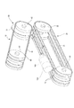
図1乃至図6は、本発明の実施形態に係るペットボトル回収装置の構成を示す図である。図1は、ペットボトル回収装置の全体構造を示す図であり、(a)は正面図、(b)は側面断面図、(c)は背面断面図である。
本実施形態のペットボトル回収装置は、使用済みのペットボトル100をフレーク状に裁断して回収する装置である。図1に示すように、このペットボトル回収装置は、底部にキャスター2が取り付けられて移動自在となった装置本体1の内部に、ペットボトル100を裁断する各種装置が設置されている。
Hereinafter, embodiments of the present invention will be described in detail with reference to the drawings.
1 to 6 are diagrams showing a configuration of a plastic bottle collection device according to an embodiment of the present invention. 1A and 1B are diagrams showing the overall structure of a plastic bottle collecting apparatus, wherein FIG. 1A is a front view, FIG. 1B is a side sectional view, and FIG. 1C is a rear sectional view.
The PET bottle collection device of this embodiment is a device that cuts and collects used
ここで、本実施形態のペットボトル回収装置は、特に店頭や公共施設等に設置して、利用者から廃棄されるペットボトル100の回収を目的としている。したがって、装置本体1は施設に設置可能な大きさに小型化されており、さらに廃棄されるペットボトル100のサイズは市販されている280ml乃至2Lの容器に対応している。また、装置本体1はペットボトル100内に残った飲料水が排水される受口4が外面に設けられ、内部にある飲料タンク3に貯水される構造となっている。
なお、本発明のペットボトル回収装置は、このような一般の利用者に適用される装置に限定されないことは勿論である。例えば、回収業者が利用しやすいように、大型化したペットボトル回収装置として提供することも可能である。
Here, the plastic bottle collection device of the present embodiment is installed especially in a store or public facility, and is intended to collect the
Of course, the PET bottle collection apparatus of the present invention is not limited to such an apparatus applied to general users. For example, it can be provided as a large-sized PET bottle collection device so that it can be easily used by a collection company.
このペットボトル回収装置の装置本体1内部には、ペットボトル100の処理工程順に、ペットボトルの投入部10、キャップ切断機構20(キャップ切断手段)、搬送ベルトコンベア30(搬送手段)、圧縮ベルトコンベア40(圧縮手段)、ロータリーカッタ50(切断手段)、ラベル剥離機構60(ラベル剥離手段)、粉砕機構70(粉砕機構)が備えられている。
Inside the apparatus
図2は、本実施形態に係るペットボトル回収装置に回収されたペットボトルの処理工程を示す模式図である。
先にペットボトル100の回収処理工程について簡単に説明すると、図2に示すように、キャップ付きのペットボトル100は、利用者によって、キャップ部101側を先端として投入部10から装置本体1内に投入される。投入されたペットボトル100は、すぐ下流に設けられたキャップ切断機構20によって、先端側のキャップ部101が切断され、胴体部102のみとなる。続いて、ペットボトル100は、搬送ベルトコンベア30によって上流から下流に搬送される。さらに搬送ベルトコンベア30の下流側では、上部に設けられた圧縮ベルトコンベア40によって胴体部102が圧縮されながら搬送されていく。
FIG. 2 is a schematic diagram illustrating a process of processing a plastic bottle collected by the plastic bottle collection apparatus according to the present embodiment.
Briefly explaining the process of collecting the
そして、搬送ベルトコンベア30の終端位置に設けられたロータリーカッタ50によって、ペットボトル100は圧縮された状態のまま、略中央部分から縦割りに切断される。ここで、胴体部102には商品を表示するラベル103が胴巻きされていることが一般的である。ラベル103は胴体部102とともに縦割りに切断され、さらにラベル剥離機構60によって胴体部102から取り除かれる。その後、切断されたペットボトル100は、粉砕機構70へと排出され、粉砕機構70においてフレーク状に細かく粉砕される。このようにして、ペットボトル100は、フレーク状に生成されて蓄えられ、回収業者によって適宜回収されることになる。
Then, the
次に、ペットボトル回収装置の各構成についてそれぞれ説明していく。
図1に示すように、ペットボトル回収装置は、装置本体1の正面上部がペットボトルの投入部10となており、この投入部10に開閉扉11が設けてある。この開閉扉11は、ペットボトル100のキャップ部101側を先端として投入した場合にのみ開く機能を備えている。具体的には、この開閉扉11は待機状態(閉塞状態)において、ペットボトル100のキャップ部101のみが挿入可能な口径でキャップ差込み口11aが開口している。また、開閉扉11のすぐ背面には、キャップ差込み口11aへのキャップ部101の挿入を検知するキャップ検知センサ12が設けてある。投入部10は、ペットボトル100のキャップ部101が開閉扉11のキャップ差込み口11aに挿入されると、キャップ検知センサ12がキャップ部101を検知して、開閉扉11を開く。開放状態の開閉扉11は、ペットボトル100を長手方向に投入可能な開口面積を有している。ペットボトル100は、この開放状態にある開閉扉11を通して、装置本体1内へ投入することが可能となる。
Next, each configuration of the plastic bottle collection device will be described.
As shown in FIG. 1, in the plastic bottle collecting apparatus, the upper front portion of the apparatus
さらに、投入部10には、開閉扉11のすぐ下流に4〜8個のローラからなる送り込み機構13と、ペットボトル100が所定の位置まで送り込まれたことを検知する検知センサ14とが設けられている。送り込み機構13は、ペットボトル100が投入された後、キャップ部101の切断位置Aまでペットボトル100を送り込む。そして、検知センサ14はペットボトル100が切断位置Aに送り込まれたことを検知して、キャップ切断機構20に検知信号を送信する構成である。
Further, the
キャップ切断機構20は、ペットボトル100のキャップ部101側を挟み込んで保持するクランク機構と、このクランク機構に取り付けられた切断刃(ともに図示せず)とを備えた構成である。クランク機構及び切断刃は、ペットボトル100の切断位置Aにおいて、ちょうどキャップ部101と胴体部102を切断させることが可能な位置に設置されている。これにより、キャップ切断機構20は、ペットボトル100が切断位置Aに配置された後に、検知センサ14から検知信号を受けて、クランク機構を駆動させ、切断刃によってキャップ部101を切断することができる。
なお、ペットボトル100から切断されたキャップ部101は、図示しない廃棄経路を通り、装置内の不用部回収ボックス21に排出される。
The
In addition, the
図3は、本実施形態に係るペットボトル回収装置の搬送ベルトコンベア及び圧縮ベルトコンベアを拡大して示す図であり、(a)は側面図、(b)は背面図である。また、図4、図5は、同じく搬送ベルトコンベア及び圧縮ベルトコンベアによって搬送されるペットボトルの動作を示す斜視図である。
図3及び図4に示すように、搬送ベルトコンベア30は、金属片がベルト状に連なるチェーンベルト31と、このチェーンベルト31を上流から下流に移動させるスプロケット32とにより構成される。チェーンベルト31は、スプロケット32の回転駆動により、その上面を上流から下流に平行移動させる。したがって、搬送ベルトコンベア30は、切断位置Aから落下されたペットボトル100を載せて下流に搬送することができる。
FIG. 3 is an enlarged view showing the conveyor belt conveyor and the compression belt conveyor of the PET bottle collecting apparatus according to the present embodiment, wherein (a) is a side view and (b) is a rear view. 4 and 5 are perspective views showing the operation of the PET bottles conveyed by the conveyor belt conveyor and the compression belt conveyor.
As shown in FIGS. 3 and 4, the
搬送ベルトコンベア30のチェーンベルト31は、ちょうどペットボトル100が載る中心位置の間隔を少し開けて左右対称に設けられている。搬送ベルトコンベア30は、この中心位置を境にチェーンベルト31が一定のトルクで駆動することにより、ペットボトル100を常に中心位置に保って搬送する構成である。また、チェーンベルト31上の両側には、図示しないサイドガイドが設けられており、搬送されるペットボトル100を搬送ベルトコンベア30の中心位置に案内している。
The
さらに、チェーンベルト31の表面には、複数の突起部材33が任意の間隔で設けられている。この突起部材33は、ペットボトル100の搬送時に、ペットボトル100が引っかかることとなり、これによって上流から下流への搬送を補助している。
Further, a plurality of protruding
圧縮ベルトコンベア40は、上述した搬送ベルトコンベア30と同じく、チェーンベルト41、スプロケット42、突起部材43が備えられている。この圧縮ベルトコンベア40は、搬送ベルトコンベア30の上部に設置され、チェーンベルト41の下面側がペットボトル100の搬送方向と同方向に駆動する構成である。また、圧縮ベルトコンベア40は、搬送ベルトコンベア30の上方に配設され、下流側斜め上方から当該コンベア30の終端位置に向かって延びている。搬送ベルトコンベア30の終端位置では、圧縮ベルトコンベア40との間が狭小な間隔となるよう調整されている。
The
したがって、図5に示すように、搬送ベルトコンベア30によって搬送されるペットボトル100は、搬送ベルトコンベア30と圧縮ベルトコンベア40との間に徐々に挟まれて上下方向から圧縮されていく。このようにペットボトル100を圧縮することで、ペットボトル100の姿勢が安定化し、次の切断工程において円滑且つ容易に胴体部102を切断することが可能となる。また、ペットボトル100を、搬送ベルトコンベア30と圧縮ベルトコンベア40とで挟み込むことにより、切断時にペットボトル100が位置ずれし難くなるので、いっそう安定して当該胴体部102を切断することができる。
Therefore, as shown in FIG. 5, the
この圧縮ベルトコンベア40と搬送ベルトコンベア30は、圧縮ベルトコンベア40の通過する終端位置において、胴体部102が弾性的に復元可能な押圧力となるように、互いの間隔が調整されている。これにより、ペットボトル100は、圧縮ベルトコンベア40から抜け出される際に、押圧された形状から積極的に復元する。このとき、ラベル103はペットボトル100の復元力をもって当該ペットボトル100の表面から弾いて浮き上がる。その結果、ラベル103の剥離工程において、ラベル103を容易且つ確実にペットボトル100から剥離することが可能となる。
The distance between the
また、圧縮ベルトコンベア40のチェーンベルト41に設けられた突起部材43は、搬送ベルトコンベア30の突起部材31とともに、胴体部102が圧縮ベルトコンベア40に押圧された際に引っかかり、胴体部102の下流へ搬送を補助する役割を果たしている。この突起部材33、43により、ペットボトル100は、チェーンベルト31上で空回りすることなく確実に搬送されることが可能となる。
Further, the protruding
図6は、本実施形態に係るペットボトル回収装置の搬送ベルトコンベア及びロータリーカッタを拡大して示す図であり、(a)は背面方向からの斜視図、(b)、(c)は胴体部の切断を模式的に示した斜視図である。
図6(a)に示すように、ロータリーカッタ50は、金属材を円盤形状に形成した回転刃51と受け刃52とを有している。この回転刃51は、圧縮ベルトコンベア40の下流側にあるスプロケット42間に設けられ、また受け刃52は搬送ベルトコンベア30の下流側にあるスプロケット32間で回転刃51を挟むように2枚設けられている。回転刃51は、搬送ベルトコンベア30で搬送されてくるペットボトル100の略中央位置を、受け刃52と協働して縦割りに切断する。
FIG. 6 is an enlarged view showing the conveyor belt conveyor and the rotary cutter of the PET bottle collecting apparatus according to the present embodiment, where (a) is a perspective view from the back side, and (b) and (c) are the body parts. It is the perspective view which showed the cutting | disconnection of typically.
As shown in FIG. 6A, the
また、ロータリーカッタ50の両側部にはラベル剥離機構60が配置されている。本実施形態のラベル剥離機構60は、多数の針金が延出した円筒状の回転ブラシ61であり、この回転ブラシ61は回転刃51の両側部に回転自在に一対設置されている。この回転ブラシ61は、ペットボトル100の搬送方向に対向して回転している。よって、胴体部102が回転刃51によって切断された際には、この回転ブラシ61がペットボトル100のラベル103に接触して、ラベル103をペットボトルから取り除くことができる。なお、回転ブラシ61により取り除かれたラベル103は、図示しない廃棄経路を通り、キャップ部101が排出されている不用部回収ボックス21に廃棄される。
In addition,
ここで、本実施形態のロータリーカッタ50及びラベル剥離機構60の動作について詳述すると、搬送ベルトコンベア30のチェーンベルト31上に載せられたペットボトル100は、圧縮ベルトコンベア40によって圧縮された状態で切断装置50まで搬送される。図6(b)に示すように、切断装置50では、ペットボトル100が圧縮された状態のまま回転刃51に当接し、さらに搬送されていく過程で縦方向に二つに切断されていく。このとき、ペットボトル100に装着されているラベル103も縦割りに切断される。
Here, the operation of the
さらに、ペットボトル100は、図6(c)に示すように、回転刃51によって切断されながら下流に搬送されて、搬送ベルトコンベア30の終端位置から下流側へ排出される。既述したように、圧縮されていたペットボトル100は、搬送ベルトコンベア30の終端位置から排出された際、弾性的に復元する力が働き、これにより切断されたラベル103が外部方向に弾かれる。このとき、ラベル剥離機構60の回転ブラシ61が回転刃51の両側部において、ペットボトル100の搬送方向に対向して回転しているため、弾かれたラベル103が回転ブラシ61の針金に引っ掛かり、ラベル103が効果的に取り除かれる。また、縦割りに切断されたペットボトル100は、搬送してきたチェーンベルト31から排出されて、下流にある裁断装置70に投入される。
Furthermore, as shown in FIG. 6C, the
図1に示すように、ペットボトル回収装置の裁断装置70は、二つに切断されたペットボトル100をフレーク状に裁断する機能を有している。この裁断装置70の内部には、図示しない回転式のカッターと固定刃が設けられている。裁断装置70はカッターが回転して固定刃と挟み合うことで装置内に投入されたペットボトル100が粉砕される。ペットボトル100は、予め二つに切断されていることで、回転中のカッターに挟まれやすくなり、裁断をいっそう効率的に実施させることができる。また、この裁断装置70の下部には、フレーク用回収ボックス71が設けてあり、裁断されたフレーク状のペットボトル100が蓄積されることになる。
As shown in FIG. 1, the cutting
以上のようにして、ペットボトル回収装置は、投入されたペットボトル100をフレーク状にして回収することができる。このペットボトル回収装置は、ペットボトル100を押圧しながら搬送し、二つに切断することで、ラベル103を容易に取り除き、裁断装置70において効率的に裁断させることができる。したがって、装置全体の稼働効率を向上させ、ペットボトル100の回収を間断なくスムーズに実施することができる。
なお、本発明は、上述した実施形態に限定されるものではなく、例えば、以下に示すような変形例や応用例をもって構成することも可能である。
As described above, the PET bottle collecting apparatus can collect the inputted
In addition, this invention is not limited to embodiment mentioned above, For example, it is also possible to comprise with the modification and application example as shown below.
〔変形例1〕
ペットボトル回収装置の投入部10は、熱感知センサを開閉扉11付近に設けてもよい。この熱感知センサは、人間の手の挿入を感知することができ、装置全体の稼働を停止させる構成である。これにより、ペットボトル回収装置は、装置を使い慣れていない利用者などに対し安全性を確保することができる。
[Modification 1]
The charging
〔変形例2〕
ペットボトル回収装置の投入部10は、アルミ感知センサを開閉扉11付近に設けてもよい。このアルミ感知センサは、アルミ材のペットボトルの挿入を感知することができる。このアルミ感知センサの信号を受けた場合、開閉扉が開かない構成にすることで、アルミ材のペットボトルを投入させない装置とすることができる。
[Modification 2]
The charging
〔変形例3〕
また、ペットボトル回収装置のキャップ切断手段は、ペットボトルの搬送経路中に設けずに、ペットボトル100を投入部10に投入する前段階において、キャップ部101を切断させてもよい。すなわち、ペットボトル100を廃棄する利用者が、別に設けたキャップ切断機構によってペットボトル100のキャップ101を予め切断し、その後ペットボトル100のみを装置本体1内に投入する構成とすることができる。したがって、装置本体1の内部構造をより簡素化させることができ、ペットボトル100を連続的に裁断することが可能となる。
[Modification 3]
In addition, the cap cutting means of the PET bottle collecting apparatus may cut the
〔変形例4〕
業務用として、投入部10の位置に開閉扉11を設けず、代わりに連続投入を可能とするガイド機構を設け、大容量のペットボトルを連続処理できるようにすることもできる。
[Modification 4]
For business use, the opening / closing
1:装置本体、2:キャスター、3:飲料タンク、4:受口、
10:投入部、11:開閉扉、11a:キャップ差込み口、12:キャップ検知センサ、13:送り込み機構、14:検知センサ、
20:キャップ切断手段、21:不用部回収ボックス、
30:搬送ベルトコンベア、31:チェーンベルト、32:スプロケット、33:突起部材、
40:圧縮ベルトコンベア、41:チェーンベルト、42:スプロケット、43:突起部材、
50:ロータリーカッタ、51:回転刃、52:受け刃、
60:ラベル剥離機構、61:回転ブラシ、
70:粉砕機構、71:フレーク用回収ボックス、
100:ペットボトル、101:キャップ部、102:胴体部、103:ラベル、
A:切断位置
1: device body, 2: caster, 3: beverage tank, 4: receiving port,
10: loading part, 11: open / close door, 11a: cap insertion port, 12: cap detection sensor, 13: feeding mechanism, 14: detection sensor,
20: Cap cutting means, 21: Waste part collection box,
30: Conveyor belt conveyor, 31: Chain belt, 32: Sprocket, 33: Projection member,
40: Compression belt conveyor, 41: Chain belt, 42: Sprocket, 43: Projection member,
50: rotary cutter, 51: rotating blade, 52: receiving blade,
60: Label peeling mechanism, 61: Rotating brush,
70: crushing mechanism, 71: collection box for flakes,
100: plastic bottle 101: cap part 102: body part 103: label
A: Cutting position
Claims (7)
(イ)あらかじめキャップ部を切除してあるペットボトルを搬送するための搬送手段
(ロ)前記搬送手段と協働して、搬送過程にあるペットボトルを上下方向から圧縮する圧縮手段
(ハ)前記圧縮手段によって圧縮されたペットボトルの幅方向略中央位置を縦割りに切断する切断手段
(ニ)前記切断手段によって切断されたペットボトルに外装されているラベルを、ペットボトルから剥離するラベル剥離手段
(ホ)前記切断手段によって切断された前記ペットボトルを細かいフレーク状に裁断する粉砕手段 A plastic bottle collection device comprising the following configurations (a) to (e):
(A) Conveying means for conveying a PET bottle whose cap portion has been cut in advance (b) Compressing means for compressing the PET bottle in the conveying process from above and below in cooperation with the conveying means (c) Cutting means for vertically cutting the substantially central position in the width direction of the PET bottle compressed by the compressing means. (D) Label peeling means for peeling the label externally attached to the PET bottle cut by the cutting means from the PET bottle. (E) Crushing means for cutting the PET bottle cut by the cutting means into fine flakes
前記圧縮手段は、前記搬送ベルトコンベアの下流側の斜め上方から、当該コンベアの終端位置に向かって配設された圧縮ベルトコンベアで構成されており、
ペットボトルは、これら搬送ベルトコンベアと圧縮ベルトコンベアとの間に挟まれて圧縮され、前記搬送コンベアの終端位置でもっとも圧縮された状態となることを特徴とする請求項1又は2のペットボトル回収装置。 The transport means is a transport belt conveyor disposed substantially horizontally,
The compression means is composed of a compression belt conveyor disposed obliquely from the downstream side of the conveyor belt conveyor toward the terminal end position of the conveyor,
3. The PET bottle collection according to claim 1, wherein the PET bottle is compressed by being sandwiched between the conveyor belt conveyor and the compression belt conveyor, and is most compressed at the end position of the conveyor. apparatus.
(a)閉塞状態では、キャップ付きペットボトルのキャップ部分を差込み可能なキャップ差込み口が中央部に開いている。
(b)開放状態では、ペットボトルを長手方向に投入可能な開口が開く。
(c)前記キャップ差込み口にペットボトルのキャップ部分が差し込まれたとき、これを検知するキャップ検知センサが設けられており、当該キャップ検知センサがペットボトルのキャップ部分を検知したとき、前記閉塞状態から開放状態に変わる。 6. An opening / closing door having the following configurations (a) to (c) is provided upstream of the conveying means, and a plastic bottle is inserted from the opening / closing door. The plastic bottle collection device according to any one of the above.
(A) In the closed state, a cap insertion port into which a cap portion of a PET bottle with a cap can be inserted is open at the center.
(B) In the open state, an opening capable of feeding a PET bottle in the longitudinal direction is opened.
(C) When a cap part of a plastic bottle is inserted into the cap insertion port, a cap detection sensor for detecting the cap part is provided, and when the cap detection sensor detects the cap part of the plastic bottle, the closed state Changes from open to open.
Priority Applications (1)
| Application Number | Priority Date | Filing Date | Title |
|---|---|---|---|
| JP2006256225A JP2008073964A (en) | 2006-09-21 | 2006-09-21 | Plastic bottle recovery device |
Applications Claiming Priority (1)
| Application Number | Priority Date | Filing Date | Title |
|---|---|---|---|
| JP2006256225A JP2008073964A (en) | 2006-09-21 | 2006-09-21 | Plastic bottle recovery device |
Publications (1)
| Publication Number | Publication Date |
|---|---|
| JP2008073964A true JP2008073964A (en) | 2008-04-03 |
Family
ID=39346521
Family Applications (1)
| Application Number | Title | Priority Date | Filing Date |
|---|---|---|---|
| JP2006256225A Pending JP2008073964A (en) | 2006-09-21 | 2006-09-21 | Plastic bottle recovery device |
Country Status (1)
| Country | Link |
|---|---|
| JP (1) | JP2008073964A (en) |
Cited By (9)
| Publication number | Priority date | Publication date | Assignee | Title |
|---|---|---|---|---|
| JP2015100948A (en) * | 2013-11-22 | 2015-06-04 | 普 山田 | Pet bottle treatment device and vehicle mounted with pet bottle treatment device |
| JP2015100949A (en) * | 2013-11-22 | 2015-06-04 | 普 山田 | Pet bottle treatment device and pet bottle treatment device-mounted vehicle |
| US9352366B2 (en) | 2013-11-22 | 2016-05-31 | Susumu Yamada | Plastic bottle processing apparatus and vehicle having same mounted thereon |
| CN109203547A (en) * | 2018-09-28 | 2019-01-15 | 南京工业职业技术学院 | Beverage bottle recycles garbage apparatus |
| CN111070486A (en) * | 2020-01-08 | 2020-04-28 | 陈莲红 | Semi-automatic convenient mineral water bottle takes off mark machine |
| CN112845120A (en) * | 2021-01-14 | 2021-05-28 | 广州市明顿包装制品有限公司 | Visual detection equipment and method for packaging bottle |
| CN114347315A (en) * | 2021-12-24 | 2022-04-15 | 江苏力赛柯环保材料科技有限公司 | Automatic plastic bottle recycling equipment and production process of PET bottle flake reclaimed materials |
| CN114434669A (en) * | 2022-02-23 | 2022-05-06 | 南京迈森智能装备有限公司 | Reclaimed plastic granulation device |
| WO2022203629A1 (en) * | 2021-03-23 | 2022-09-29 | Yeditepe Universitesi | Waste bottle collection and separation device and method |
-
2006
- 2006-09-21 JP JP2006256225A patent/JP2008073964A/en active Pending
Cited By (12)
| Publication number | Priority date | Publication date | Assignee | Title |
|---|---|---|---|---|
| JP2015100948A (en) * | 2013-11-22 | 2015-06-04 | 普 山田 | Pet bottle treatment device and vehicle mounted with pet bottle treatment device |
| JP2015100949A (en) * | 2013-11-22 | 2015-06-04 | 普 山田 | Pet bottle treatment device and pet bottle treatment device-mounted vehicle |
| US9352366B2 (en) | 2013-11-22 | 2016-05-31 | Susumu Yamada | Plastic bottle processing apparatus and vehicle having same mounted thereon |
| CN109203547A (en) * | 2018-09-28 | 2019-01-15 | 南京工业职业技术学院 | Beverage bottle recycles garbage apparatus |
| CN109203547B (en) * | 2018-09-28 | 2023-07-25 | 南京工业职业技术学院 | Beverage bottle garbage recycling device |
| CN111070486A (en) * | 2020-01-08 | 2020-04-28 | 陈莲红 | Semi-automatic convenient mineral water bottle takes off mark machine |
| CN112845120A (en) * | 2021-01-14 | 2021-05-28 | 广州市明顿包装制品有限公司 | Visual detection equipment and method for packaging bottle |
| CN112845120B (en) * | 2021-01-14 | 2024-04-12 | 广州市明顿包装制品有限公司 | Visual inspection equipment and method for packaging bottles |
| WO2022203629A1 (en) * | 2021-03-23 | 2022-09-29 | Yeditepe Universitesi | Waste bottle collection and separation device and method |
| CN114347315A (en) * | 2021-12-24 | 2022-04-15 | 江苏力赛柯环保材料科技有限公司 | Automatic plastic bottle recycling equipment and production process of PET bottle flake reclaimed materials |
| CN114434669A (en) * | 2022-02-23 | 2022-05-06 | 南京迈森智能装备有限公司 | Reclaimed plastic granulation device |
| CN114434669B (en) * | 2022-02-23 | 2023-08-18 | 南京迈森智能装备有限公司 | Regenerated plastic granulating device |
Similar Documents
| Publication | Publication Date | Title |
|---|---|---|
| JP2008073964A (en) | Plastic bottle recovery device | |
| US5947395A (en) | Materials reducing machine | |
| JP5788283B2 (en) | Label separator for plastic containers | |
| JP2000325815A (en) | Device for treating packed garbage | |
| JP2004330265A (en) | Reinforcing bar cutting device | |
| JP3600896B2 (en) | Automatic cap removal device | |
| CN113600590B (en) | Industry is useless pretreatment of system admittedly | |
| JP2008023666A (en) | Bag forming unit | |
| JP2013063534A (en) | Plastic bottle crushing and recovering device | |
| JP2000141373A (en) | Pet bottle regenerative treating device | |
| JP3878996B2 (en) | Method and apparatus for recovering metal from printed circuit board | |
| JP3176357B2 (en) | Bag breaking machine | |
| KR20020060787A (en) | Gabage bag tearing device | |
| CN211221582U (en) | Label removing device and plastic bottle processing equipment | |
| CN213830521U (en) | Novel die cutting machine | |
| CN107008966A (en) | A kind of welding machine sheared edge silk carrying method and its system and device | |
| JP2010083128A (en) | Pet bottle compressing apparatus | |
| JPH03262550A (en) | Can recovering apparatus | |
| JP3295549B2 (en) | Large bag breaker | |
| JPH11197529A (en) | Pet bottle cutter | |
| JP2003159544A (en) | Bag breaking apparatus | |
| CN218342590U (en) | Smashing device for plastic products | |
| CN217012743U (en) | Stripping device | |
| CN210058605U (en) | Iron removing machine | |
| KR20220144576A (en) | Waste styrofoam crusher capable of removing waste stickers |