JP2008049941A - Gas generator - Google Patents
Gas generator Download PDFInfo
- Publication number
- JP2008049941A JP2008049941A JP2006230326A JP2006230326A JP2008049941A JP 2008049941 A JP2008049941 A JP 2008049941A JP 2006230326 A JP2006230326 A JP 2006230326A JP 2006230326 A JP2006230326 A JP 2006230326A JP 2008049941 A JP2008049941 A JP 2008049941A
- Authority
- JP
- Japan
- Prior art keywords
- holder
- annular substrate
- housing
- igniter assembly
- igniter
- Prior art date
- Legal status (The legal status is an assumption and is not a legal conclusion. Google has not performed a legal analysis and makes no representation as to the accuracy of the status listed.)
- Pending
Links
Images
Classifications
-
- B—PERFORMING OPERATIONS; TRANSPORTING
- B60—VEHICLES IN GENERAL
- B60R—VEHICLES, VEHICLE FITTINGS, OR VEHICLE PARTS, NOT OTHERWISE PROVIDED FOR
- B60R21/00—Arrangements or fittings on vehicles for protecting or preventing injuries to occupants or pedestrians in case of accidents or other traffic risks
- B60R21/02—Occupant safety arrangements or fittings, e.g. crash pads
- B60R21/16—Inflatable occupant restraints or confinements designed to inflate upon impact or impending impact, e.g. air bags
- B60R21/26—Inflatable occupant restraints or confinements designed to inflate upon impact or impending impact, e.g. air bags characterised by the inflation fluid source or means to control inflation fluid flow
- B60R2021/26011—Inflatable occupant restraints or confinements designed to inflate upon impact or impending impact, e.g. air bags characterised by the inflation fluid source or means to control inflation fluid flow using a filter through which the inflation gas passes
-
- B—PERFORMING OPERATIONS; TRANSPORTING
- B60—VEHICLES IN GENERAL
- B60R—VEHICLES, VEHICLE FITTINGS, OR VEHICLE PARTS, NOT OTHERWISE PROVIDED FOR
- B60R21/00—Arrangements or fittings on vehicles for protecting or preventing injuries to occupants or pedestrians in case of accidents or other traffic risks
- B60R21/02—Occupant safety arrangements or fittings, e.g. crash pads
- B60R21/16—Inflatable occupant restraints or confinements designed to inflate upon impact or impending impact, e.g. air bags
- B60R21/26—Inflatable occupant restraints or confinements designed to inflate upon impact or impending impact, e.g. air bags characterised by the inflation fluid source or means to control inflation fluid flow
- B60R2021/26029—Ignitors
Landscapes
- Physics & Mathematics (AREA)
- Fluid Mechanics (AREA)
- Engineering & Computer Science (AREA)
- Mechanical Engineering (AREA)
- Air Bags (AREA)
Abstract
Description
本発明は、ガス発生器と、前記ガス発生器の組立法として適した点火器組立体の固定方法に関する。 The present invention relates to a gas generator and a fixing method of an igniter assembly suitable as a method for assembling the gas generator.
自動車に搭載するエアバッグ装置には、ガス発生源としてのガス発生剤を備えたガス発生器が使用されており、更に前記ガス発生剤を着火燃焼させるための電気式点火器を備えている。電気式点火器は、金属部材と樹脂により固定されたものが汎用されており、前記金属部材をガス発生器のハウジングに溶接固定することで取り付けられている
ハウジングに対して、溶接法により点火器を固定するとき、溶接時の熱により、点火器の樹脂部分が変形したり、点火器の着火薬が燃焼したりするおそれもある。 When the igniter is fixed to the housing by a welding method, the resin part of the igniter may be deformed or the ignition agent of the igniter may burn due to heat during welding.
本発明は、溶接法を適用することなく、ハウジングに点火器組立体が固定されたガス発生器を提供することを課題とする。 An object of the present invention is to provide a gas generator in which an igniter assembly is fixed to a housing without applying a welding method.
また、本発明は、ハウジングに点火器組立体を固定する方法を提供することを他の課題とする。 Another object of the present invention is to provide a method for fixing an igniter assembly to a housing.
本発明は、課題の解決手段として、
ガス排出口を有するハウジングと、ガス発生剤が収容された1又は2以上の燃焼室と、前記ガス排出口と前記燃焼室の間に配置された筒状フィルタと、前記ガス発生剤を着火燃焼させるための1又は2以上の点火手段として、電気式点火器が金属部材と樹脂で包囲固定されている点火器組立体を有するガス発生器であって、
前記点火器組立体が、樹脂部分にホルダ収容空間を有しており、前記ハウジング底部に形成された開口部に前記ホルダ収容空間が正対するように配置され、前記開口部に対して外側から嵌め込んだホルダで固定されたものであり、
前記ホルダ収容空間の内壁面が凹凸部を有し、前記ホルダが凹凸部を有しており、前記ホルダ収容空間の内壁面の凹凸部と前記ホルダの凹凸部が互いに噛み合った状態になっていることで、前記点火器組立体が前記ハウジング底部に溶接されることなく固定されているガス発生器を提供する。
As a means for solving the problems, the present invention
A housing having a gas exhaust port, one or more combustion chambers containing a gas generating agent, a cylindrical filter disposed between the gas exhaust port and the combustion chamber, and igniting and burning the gas generating agent A gas generator having an igniter assembly in which an electric igniter is surrounded and fixed by a metal member and a resin as one or more ignition means for causing
The igniter assembly has a holder housing space in the resin portion, and is disposed so that the holder housing space faces the opening formed in the bottom of the housing, and is fitted from the outside to the opening. It is fixed with a holder
The inner wall surface of the holder housing space has an uneven portion, the holder has an uneven portion, and the uneven portion of the inner wall surface of the holder housing space and the uneven portion of the holder are in mesh with each other. Thus, a gas generator is provided in which the igniter assembly is fixed to the bottom of the housing without being welded.
本発明のガス発生器は、ホルダを使用することで、抵抗溶接やレーザ溶接等の溶接法を適用することなく、ハウジング底部に点火器組立体が固定されているものであり、ガス発生剤が充填された燃焼室が1つで点火器が1つのシングル型、ガス発生剤が充填された燃焼室が2つで点火器が2つのデュアル型のガス発生器のいずれでもよい。ホルダ収容空間にホルダを嵌め込んだあとの空間が、リードワイヤを介して電源と接続する手段となるコネクタの接続空間となる。 The gas generator of the present invention uses a holder so that the igniter assembly is fixed to the bottom of the housing without applying a welding method such as resistance welding or laser welding. The gas generator may be either a single type of combustion chamber filled with one igniter or a dual type gas generator with two combustion chambers filled with a gas generating agent and two igniters. The space after the holder is fitted into the holder accommodating space is a connector connection space that is a means for connecting to the power source via the lead wire.
ホルダ収容空間の内壁面に形成された凹凸は、周方向に連続した複数の溝の組み合わせでもよいし、独立した複数の凹部と凸部の組み合わせでもよいし、又は溝と、独立した凹部と凸部の組み合わせでもよい。 The unevenness formed on the inner wall surface of the holder housing space may be a combination of a plurality of grooves continuous in the circumferential direction, a combination of a plurality of independent recesses and protrusions, or a groove, an independent recess and protrusion. A combination of parts may be used.
ホルダの形状は特に制限されず、ホルダ収容空間に嵌め込むことができ、ホルダ収容空間の内壁面の凹凸部と、ホルダの凹凸部が互いに噛み合った状態にできるものであればよい。ホルダは、ホルダ収容空間に嵌め込むものであり、前記空間の内壁面は樹脂製であるから、ホルダ自体も樹脂製にすることが好ましい。 The shape of the holder is not particularly limited as long as it can be fitted into the holder accommodating space and the concave and convex portions on the inner wall surface of the holder accommodating space and the concave and convex portions of the holder can be engaged with each other. Since the holder is fitted into the holder housing space, and the inner wall surface of the space is made of resin, the holder itself is preferably made of resin.
本発明は、課題の他の解決手段として、
前記ホルダが、環状基板と、前記環状基板上の2箇所以上に突設された爪部を有し、前記爪部が、弾力性のある材質からなり、凹凸を有する板状のもので、先端部が前記環状基板の外周縁方向に拡げられるように突設されたものであり、
前記ホルダの環状基板が、前記ハウジング底部に形成された開口部に外側から嵌め込まれており、
前記ホルダ収容空間の内壁面の凹凸部と前記爪部の凹凸部が互いに噛み合った状態であり、かつ前記爪部の先端部が外側に拡がる力により、前記ホルダ収容空間の内壁面が押圧されていることで、前記点火器組立体が前記ハウジング底部に溶接されることなく固定されている請求項1記載のガス発生器を提供する。
The present invention provides other means for solving the problems,
The holder has an annular substrate and claw portions protruding at two or more locations on the annular substrate, and the claw portion is made of an elastic material and has a plate shape having irregularities, The part is provided so as to expand in the direction of the outer peripheral edge of the annular substrate,
The annular substrate of the holder is fitted from the outside into an opening formed in the bottom of the housing,
The inner wall surface of the holder housing space is pressed by the force that the uneven portion of the inner wall surface of the holder housing space and the uneven portion of the claw portion mesh with each other and the tip of the claw portion expands outward. The gas generator according to claim 1, wherein the igniter assembly is fixed to the bottom of the housing without being welded.
ホルダは、環状基板上の2箇所以上に爪部を有するものであり、例えば、対向する位置に2箇所の爪部を有するもの、等間隔で周方向に分離配置された3つ、4つ又はそれ以上の爪部を有するものを用いることができる。 The holder has claw portions at two or more places on the annular substrate. For example, the holder has two claw portions at opposing positions, three, four, or What has the nail | claw part beyond it can be used.
例えば、対向する位置に形成された2つの爪部先端部の間隔は、ホルダ収容空間の間隔よりも広くなっている。このため、ホルダ収容空間にホルダを嵌め込むときは、互いの間隔を小さくするように2つの爪部を両側から押し縮めながら嵌め込むと、今度は押し縮められた2つの爪部が外側に拡がるように変形するため、上記したとおり、爪部の先端部が外側に拡がる力により、前記ホルダ収容空間の内壁面が押圧される。 For example, the distance between the tip portions of the two claw parts formed at the opposing positions is wider than the distance between the holder housing spaces. For this reason, when the holder is fitted in the holder accommodating space, if the two claws are fitted while being compressed from both sides so as to reduce the distance between the two, the two claws that have been compressed are now expanded outward. Therefore, as described above, the inner wall surface of the holder housing space is pressed by the force that the tip of the claw portion expands outward.
このようにすることで、ホルダ収容空間の内壁面と爪部の凹凸同士が噛み合うことに加えて、爪部がコネクタ収容空間の内壁面を押圧するため、点火器組立体の固定強度がより高められる。 In this way, the inner wall surface of the holder housing space and the projections and recesses of the claw portion mesh with each other, and the claw portion presses the inner wall surface of the connector housing space, so that the fixing strength of the igniter assembly is further increased. It is done.
本発明は、課題の他の解決手段として、
前記ホルダが、第1環状基板と、前記第1環状基板上に形成された、前記第1環状基板よりも小さな径の第2環状基板と、前記第2環状基板上の2箇所以上に突設された爪部を有し、前記爪部が、弾力性のある材質からなり、凹凸を有する板状のもので、先端部が前記第2環状基板の外周縁方向に拡げられるように突設されたものであり、
前記ハウジング底部の外表面に対して、前記第1環状基板と前記第2環状基板の段差面が当接され、前記ハウジング底部に形成された開口部に前記第2環状基板が嵌め込まれており、
前記ホルダ収容空間の内壁面の凹凸部と前記爪部の凹凸部が互いに噛み合った状態であり、かつ前記爪部の先端部が外側に拡がる力により、前記ホルダ収容空間の内壁面が押圧されていることで、前記点火器組立体が前記ハウジング底部に溶接されることなく固定されている請求項1記載のガス発生器を提供する。
The present invention provides other means for solving the problems,
The holder protrudes at two or more locations on the first annular substrate, a second annular substrate formed on the first annular substrate and having a smaller diameter than the first annular substrate, and the second annular substrate. The claw portion is made of an elastic material, and is a plate-like one having irregularities, and the tip portion is projected so as to be expanded in the outer peripheral edge direction of the second annular substrate. And
The step surface of the first annular substrate and the second annular substrate is brought into contact with the outer surface of the housing bottom, and the second annular substrate is fitted into an opening formed in the housing bottom,
The inner wall surface of the holder housing space is pressed by the force that the uneven portion of the inner wall surface of the holder housing space and the uneven portion of the claw portion mesh with each other and the tip of the claw portion expands outward. The gas generator according to claim 1, wherein the igniter assembly is fixed to the bottom of the housing without being welded.
ホルダとして、第1環状基板、第2環状基板及び爪部を有するものを用いることにより、ハウジング底部への取り付け作業が容易になる。そして、ホルダ収容空間の内壁面と爪部の凹凸同士が噛み合うことに加えて、爪部がコネクタ収容空間の内壁面を押圧するため、点火器組立体の固定強度がより高められる。 By using the holder having the first annular substrate, the second annular substrate, and the claw portion, the attaching operation to the bottom of the housing is facilitated. And since the claw part presses the inner wall surface of a connector accommodation space in addition to the unevenness | corrugation of the inner wall surface of a holder accommodation space and a nail | claw part engaging, the fixed strength of an igniter assembly is raised more.
本発明は、課題の他の解決手段として、更に薬剤収容室を形成するカップ部材を有しており、前記カップ部材が、底面が前記ハウジング天井面に当接され、開口部周縁が前記点火器カラーに当接されて配置されている請求項1〜3のいずれかに記載のガス発生器を提供する。 As another means for solving the problems, the present invention further includes a cup member that forms a medicine accommodating chamber, the bottom surface of the cup member is in contact with the ceiling surface of the housing, and the periphery of the opening portion is the igniter. The gas generator according to claim 1, which is disposed in contact with the collar.
このようにしてカップ部材を配置することで、カップ部材により、ホルダによる点火器組立体の固定を補助することができる。なお、カップ部材により形成される薬剤収容室は、例えば、シングル型のガス発生器の場合には、燃焼室と連通された伝火薬収容室であり、デュアル型のガス発生器の場合には、ガス発生剤が収容された2つの燃焼室の内の一方である。 By arranging the cup member in this manner, the cup member can assist the fixing of the igniter assembly by the holder. The drug storage chamber formed by the cup member is, for example, a transfer charge storage chamber communicated with the combustion chamber in the case of a single type gas generator, and in the case of a dual type gas generator, One of the two combustion chambers containing the gas generant.
本発明は、他の課題の解決手段として、
ガス発生器のハウジングに対して、溶接法を適用することなく、1又は2以上の点火器組立体を固定する方法であって、
前記ハウジングが、点火手段を固定する開口部を有するクロージャシェルと、ガス排出口を有するディフューザシェルが接合一体化されてなるものであり、前記点火手段が、電気式点火器が金属部材と樹脂で包囲固定されており、前記樹脂部分がホルダ収容空間を有しているものであり、
前記点火器組立体を、前記ホルダ収容空間が前記クロージャシェルの開口部に正対する位置になるように配置する工程、
前記開口部に外側から前記ホルダを嵌め込んで、前記点火器組立体を前記クロージャシェル底面に固定する工程を有しており、前記工程において、前記ホルダ収容空間の内壁面の凹凸部に前記ホルダの凹凸部が互いに噛み合うように嵌め込むことで、前記点火器組立体を前記ハウジング底部に溶接することなく固定する点火器組立体の固定方法を提供する。
The present invention provides a solution to other problems.
A method of fixing one or more igniter assemblies to a gas generator housing without applying a welding method,
The housing is formed by joining and integrating a closure shell having an opening for fixing the ignition means and a diffuser shell having a gas discharge port. The ignition means includes an electric igniter made of a metal member and a resin. Surrounding and fixed, the resin part has a holder housing space,
Disposing the igniter assembly so that the holder-accommodating space is in a position facing the opening of the closure shell;
The holder includes a step of fitting the holder into the opening from the outside and fixing the igniter assembly to the bottom surface of the closure shell. In the step, the holder is formed on the uneven portion of the inner wall surface of the holder housing space. A method for fixing an igniter assembly is provided in which the concavo-convex portions of the igniter assembly are fitted so as to mesh with each other so that the igniter assembly is fixed to the bottom of the housing without welding.
本発明の点火器組立体の固定方法は、ホルダを使用することで、溶接法を適用することなく、ハウジング底部に点火器組立体を固定する方法であり、ガス発生剤が充填された燃焼室が1つで点火器が1つのシングル型、ガス発生剤が充填された燃焼室が2つで点火器が2つのデュアル型のガス発生器のいずれの組立工程にも適用できる。 The method for fixing an igniter assembly according to the present invention is a method for fixing an igniter assembly to the bottom of a housing by using a holder without applying a welding method, and a combustion chamber filled with a gas generating agent. Can be applied to any assembly process of a single-type gas generator with one igniter and two combustion chambers filled with a gas generating agent and two igniters.
ホルダ収容空間の内壁面に形成された凹凸は、周方向に連続した複数の溝の組み合わせでもよいし、独立した複数の凹部と凸部の組み合わせでもよいし、又は溝と、独立した凹部と凸部の組み合わせでもよい。 The unevenness formed on the inner wall surface of the holder housing space may be a combination of a plurality of grooves continuous in the circumferential direction, a combination of a plurality of independent recesses and protrusions, or a groove, an independent recess and protrusion. A combination of parts may be used.
ホルダの形状は特に制限されず、ホルダ収容空間に嵌め込むことができ、ホルダ収容空間の内壁面の凹凸部と、ホルダの凹凸部が互いに噛み合った状態にできるものであればよい。ホルダは、ホルダ収容空間に嵌め込むものであり、前記空間の内壁面は樹脂製であるから、ホルダ自体も樹脂製にすることが好ましい。 The shape of the holder is not particularly limited as long as it can be fitted into the holder accommodating space and the concave and convex portions on the inner wall surface of the holder accommodating space and the concave and convex portions of the holder can be engaged with each other. Since the holder is fitted into the holder housing space, and the inner wall surface of the space is made of resin, the holder itself is preferably made of resin.
本発明は、他の課題の他の解決手段として、
前記ホルダとして、環状基板と、前記環状基板上の2箇所以上に突設された爪部を有し、前記爪部が、弾力性のある材質からなり、凹凸を有する板状のもので、先端部が前記環状基板の外周縁方向に拡げられるように突設されたものを使用し、
前記点火器組立体を前記クロージャシェル底面に固定する工程において、前記ホルダを、前記ホルダ収容空間の内壁面の凹凸部と前記爪部の凹凸部が互いに噛み合うように嵌め込み、前記爪部の先端部が外側に拡がる力により、前記ホルダ収容空間の内壁面を押圧することで、前記点火器組立体を前記クロージャシェル底面に固定する請求項5記載の点火器組立体の固定方法を提供する。
The present invention provides other means for solving other problems,
The holder has an annular substrate and claw portions projecting at two or more places on the annular substrate, and the claw portion is made of an elastic material and has a plate-like shape having irregularities, Use the part that is projected so that the part is expanded in the outer peripheral edge direction of the annular substrate,
In the step of fixing the igniter assembly to the bottom surface of the closure shell, the holder is fitted so that the concavo-convex part of the inner wall surface of the holder housing space and the concavo-convex part of the claw part are engaged with each other, and the tip part of the claw part The igniter assembly fixing method according to claim 5, wherein the igniter assembly is fixed to the bottom surface of the closure shell by pressing an inner wall surface of the holder housing space by a force spreading outward.
ホルダは、環状基板上の2箇所以上に爪部を有するものであり、例えば、対向する位置に2箇所の爪部を有するもの、等間隔で周方向に分離配置された3つ、4つ又はそれ以上の爪部を有するものを用いることができる。 The holder has claw portions at two or more places on the annular substrate. For example, the holder has two claw portions at opposing positions, three, four, or What has the nail | claw part beyond it can be used.
例えば、対向する位置に形成された2つの爪部先端部の間隔は、ホルダ収容空間の間隔よりも広くなっている。このため、ホルダ収容空間にホルダを嵌め込むときは、互いの間隔を小さくするように2つの爪部を両側から押し縮めながら嵌め込むと、今度は押し縮められた2つの爪部が外側に拡がるように変形するため、上記したとおり、爪部の先端部が外側に拡がる力により、前記ホルダ収容空間の内壁面が押圧される。 For example, the distance between the tip portions of the two claw parts formed at the opposing positions is wider than the distance between the holder housing spaces. For this reason, when the holder is fitted in the holder accommodating space, if the two claws are fitted while being compressed from both sides so as to reduce the distance between the two, the two claws that have been compressed are now expanded outward. Therefore, as described above, the inner wall surface of the holder housing space is pressed by the force that the tip of the claw portion expands outward.
このようにすることで、ホルダ収容空間の内壁面と爪部の凹凸同士が噛み合うことに加えて、爪部がコネクタ収容空間の内壁面を押圧するため、点火器組立体の固定強度がより高められる。 In this way, the inner wall surface of the holder housing space and the projections and recesses of the claw portion mesh with each other, and the claw portion presses the inner wall surface of the connector housing space, so that the fixing strength of the igniter assembly is further increased. It is done.
本発明は、他の課題の他の解決手段として、
前記ホルダとして、第1環状基板と、前記第1環状基板上に形成された、前記第1環状基板よりも小さな径の第2環状基板と、前記第2環状基板上の2箇所以上に突設された爪部を有し、前記爪部が、弾力性のある材質からなり、凹凸を有する板状のもので、先端部が前記第2環状基板の外周縁方向に拡げられるように突設されたものを使用し、
前記点火器組立体を前記クロージャシェル底面に固定する工程において、前記ホルダを、前記ハウジング底部の外表面に対して第1環状基板と第2環状基板の段差面を当接させ、前記ホルダ収容空間の内壁面の凹凸部と前記爪部の凹凸部が互いに噛み合うように嵌め込み、前記爪部の先端部が外側に拡がる力により、前記ホルダ収容空間の内壁面を押圧することで、前記点火器組立体を前記クロージャシェル底面に固定する請求項5記載の点火器組立体の固定方法を提供する。
The present invention provides other means for solving other problems,
As the holder, a first annular substrate, a second annular substrate formed on the first annular substrate and having a smaller diameter than the first annular substrate, and projecting at two or more locations on the second annular substrate. The claw portion is made of an elastic material, and is a plate-like one having irregularities, and the tip portion is projected so as to be expanded in the outer peripheral edge direction of the second annular substrate. Use
In the step of fixing the igniter assembly to the bottom surface of the closure shell, the holder is brought into contact with the outer surface of the bottom portion of the housing so that the step surfaces of the first annular substrate and the second annular substrate are in contact with each other. The concavo-convex portion of the inner wall surface and the concavo-convex portion of the claw portion are fitted so as to mesh with each other, and the inner wall surface of the holder housing space is pressed by the force that the tip end portion of the claw portion expands outward, thereby 6. The method for fixing an igniter assembly according to claim 5, wherein a solid body is fixed to the bottom surface of the closure shell.
ホルダとして、第1環状基板、第2環状基板及び爪部を有するものを用いることにより、ハウジング底部への取り付け作業が容易になる。そして、ホルダ収容空間の内壁面と爪部の凹凸同士が噛み合うことに加えて、爪部がコネクタ収容空間の内壁面を押圧するため、点火器組立体の固定強度がより高められる。 By using the holder having the first annular substrate, the second annular substrate, and the claw portion, the attaching operation to the bottom of the housing is facilitated. And since the claw part presses the inner wall surface of a connector accommodation space in addition to the unevenness | corrugation of the inner wall surface of a holder accommodation space and a nail | claw part engaging, the fixed strength of an igniter assembly is raised more.
本発明は、他の課題の他の解決手段として、前記ホルダを使用し、前記点火器組立体を前記クロージャシェル底面に固定する工程の後、更に薬剤収容室を形成するカップ部材を、底面を前記ハウジング天井面に当接させ、開口部周縁を前記点火器カラーに当接させて配置する工程を有する請求項5〜7のいずれかに記載の点火器組立体の固定方法を提供する。 As another means for solving other problems, the present invention uses a holder, and after the step of fixing the igniter assembly to the bottom surface of the closure shell, a cup member that further forms a medicine containing chamber is provided on the bottom surface. The method for fixing an igniter assembly according to any one of claims 5 to 7, further comprising a step of abutting against the ceiling surface of the housing and arranging a peripheral edge of the opening in contact with the igniter collar.
このようにしてカップ部材を配置することで、カップ部材により、ホルダによる点火器組立体の固定を補助することができる。なお、カップ部材により形成される薬剤収容室は、例えば、シングル型のガス発生器の場合には、燃焼室と連通された伝火薬収容室であり、デュアル型のガス発生器の場合には、ガス発生剤が収容された2つの燃焼室の内の一方である。 By arranging the cup member in this manner, the cup member can assist the fixing of the igniter assembly by the holder. The drug storage chamber formed by the cup member is, for example, a transfer charge storage chamber communicated with the combustion chamber in the case of a single type gas generator, and in the case of a dual type gas generator, One of the two combustion chambers containing the gas generant.
本発明のガス発生器は、ハウジングに点火器組立体を取り付けるとき、公知の溶接法を適用する必要が無く、ホルダを嵌め込むだけで点火器組立体を取り付けることができるため、組立工程が簡略化でき、溶接時の熱により、点火器組立体の樹脂が熱変形したり、着火薬が燃焼したりするおそれもなくなる。 In the gas generator of the present invention, when the igniter assembly is attached to the housing, there is no need to apply a known welding method, and the igniter assembly can be attached simply by fitting the holder, so that the assembly process is simplified. There is no possibility that the resin of the igniter assembly is thermally deformed or the ignition agent burns due to heat during welding.
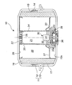
(1)ガス発生器
図1、図2により、本発明のガス発生器の実施形態を説明する。図1は、ガス発生器10の縦断面図、図2は、点火器組立体とホルダの固定状態を説明するための縦断面図である。
(1) Gas Generator An embodiment of the gas generator of the present invention will be described with reference to FIGS. FIG. 1 is a longitudinal sectional view of the
ガス発生器10の外殻を形成するハウジング11は、ディフューザシェル12とクロージャシェル13が、溶接により、接合一体化されたものである。ディフューザシェル12は、複数のガス排出口14を有しており、ガス排出口14は、内側からアルミニウムテープやステンレステープ等の閉塞部材15で閉塞されている。
The
ハウジング11内には、筒状フィルタ16が配置されている。筒状フィルタ16とガス排出口14及び閉塞部材15との間には、間隙17が形成されている。
A
ハウジング11の中央部にはカップ部材21が配置され、内部は伝火薬収容室21となっており、図示していない伝火薬が充填されている。カップ部材21の周面には複数の伝火孔24が形成されており、天井面22側にはクッション部材25が配置されている。
A
カップ部材21と筒状フィルタ16の間は燃焼室25であり、図示していないガス発生剤が充填されている。燃焼室25の天井面側のリテーナ26は、ガス発生剤の燃焼により発生したガスがフィルタ16とディフューザシェル12との接触面から漏れ出ることを防止するためのショートパス防止部材であり、底面側のリテーナ27は、ガス発生剤の充填量に応じて燃焼室容量を調整するためのものである。
Between the
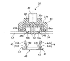
クロージャシェル13の底面13aの中央部には開口部18が形成されており、前記開口部18に臨む底面13a上には、点火器組立体30が固定されている。開口部18の周面には、2つの凸部19a、19bが形成されている。
An
点火器組立体30は、1対の導電ピンを有する電気式点火器31が、底部に導電ピンを通すための穴を有するカップ状の金属部材32と樹脂部33で包囲固定されたものである。金属部材32、樹脂部33及び底面13aで囲まれた環状溝には、Oリング39が嵌め込まれている。
The
樹脂部33の外表表面には段差が付けられ、環状の段差面33aが形成されている。樹脂部33内には、ホルダ40が嵌め込まれる前にはホルダ収容空間36a(図2参照)が形成されており、ホルダ40が嵌め込まれたあとに、コネクタ接続空間36(図1参照)が形成されている。
A step is provided on the outer surface of the
ホルダ収容空間36aは、開口部18に正対している。ホルダ収容空間36aの内壁面には、対向する位置において、凹部34aと凸部34b、凹部35aと凸部35bが形成されている。
The
ホルダ40は、第1環状基板41と、第1環状基板41上に同心円を形成するように積層された、第1環状基板41よりも小さな径の第2環状基板42と、第2環状基板42上の対向する2箇所に突設された板状の爪部44、45を有している。第1環状基板41と第2環状基板42の直径の大小に起因して、環状段差面43が形成されている。
The
ホルダ40は全体が樹脂製であり、爪部44は、外側凸部44a、外側凹部44b、内側凹部44cを有し、爪部45は、外側凸部45a、外側凹部45b、内側凹部45cを有している。そして、爪部44と爪部45は、いずれも外方向(第2環状基板42の周縁方向)に反った状態で突設されているため、ホルダ収容空間36aに嵌め込む前は、ホルダ収容空間36aの最大内径よりも、2つの爪部44、45の間隔(外側凸部44aと外側凸部45aの間隔)の方が大きくなっている。
The
ホルダ40は、環状段差面43がクロージャシェル13の底部外側面に当接され、第2環状基板42が開口部18に嵌め込まれた状態で、ホルダ収容空間36aに嵌め込まれている。
The
爪部44の外側凸部44a、外側凹部44b、内側凹部44cは、それぞれホルダ収容空間36aの内壁面の凹部34a、凸部34b、開口部周縁の凸部19aと噛み合っている。爪部45の外側凸部45a、外側凹部45b、内側凹部45cは、それぞれホルダ収容空間36aの内壁面の凹部35a、凸部35b、開口部周縁の凸部19bと噛み合っている。そして、爪部44、45は、外側に拡がるように変形しようとするため、爪部44、45により、ホルダ収容空間36aの内壁面は押圧されており、このような押圧力が、上記した凹凸同士の噛み合いによる結合力を高めている。
The outer convex portion 44a, the outer concave portion 44b, and the inner
カップ部材21は、天井面22がディフューザシェル12の天井面に当接され、開口部周縁23が樹脂部33の環状の段差面33aに当接されている。このため、樹脂部33は、上方からカップ部材21で押し付けられた状態になっており、この押し付ける力が点火組立体20のクロージャシェル13への固定を補助している。
The
ガス発生器10では、点火器組立体30はクロージャシェル13に対して、溶接することなく、ホルダ40によって固定されている。
In the
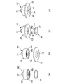
(2)点火器組立体の固定方法
図3により、本発明の点火器組立体の固定方法の実施形態を説明する。図3(a)〜(d)は、ガス発生器に点火器組立体を固定する方法の工程図である。なお、クロージャシェル13は、組立方法を理解し易いように、一部のみを表示している。
(2) Fixing method of igniter assembly An embodiment of the fixing method of the igniter assembly according to the present invention will be described with reference to FIG. FIGS. 3A to 3D are process diagrams of a method of fixing the igniter assembly to the gas generator. Note that only a part of the
図3(a)で示す工程は、点火器組立体30をクロージャシェル13に取り付ける前の準備工程であり、樹脂部33と金属部材32との間の環状溝に、防湿性付与のためのOリングを嵌め込む。
The process shown in FIG. 3A is a preparatory process before the
次に、図3(b)で示す工程において、点火器組立体30のホルダ収容空間36aがクロージャシェル13の開口部18に正対する位置になるように、点火器組立体30をクロージャシェル13上に配置する。
Next, in the step shown in FIG. 3B, the
次に、図3(c)に示す工程において、ホルダ40を開口部18に嵌め込んで、点火器組立体3をクロージャシェル13の底面13aに固定する。このとき、ホルダ40の第1環状基板41はクロージャシェル底面13a(但し、外側表面)に当接させ、対向する2つの爪部44、45を互いに近接させるように押し縮めながらホルダ収容空間36a内に入れ、第2環状基板42は開口部18に嵌め込む。
Next, in the step shown in FIG. 3C, the
このとき、開口部18の周面にある2つの凸部19a、19bに、爪部44の凹部44c、爪部45の凹部45cが嵌め込まれ、ホルダ収容空間36aの内壁面の凹凸部に、ホルダ40の2つの爪部44、45の凹凸部が嵌め込まれる。そして、押し縮められた2つの爪部44、45には、外に拡がろうとする力が生じるため、爪部44、45によりホルダ収容空間36aの内壁面が押圧され、凹凸同士の噛み合いによる結合力が高められる。
At this time, the
このため、点火器組立体30は、溶接することなく、ホルダ40のみでクロージャシェル13に対して強固に固定することができる。よって、溶接が不要になるため、組立工程が簡略化でき、溶接時の熱により、点火器組立体30の樹脂部33が熱変形したり、点火器31の着火薬が燃焼したりするおそれもなくなる。
For this reason, the
10 ガス発生器
11 ハウジング
12 ディフューザシェル
13 クロージャシェル
14 ガス排出口
16 フィルタ
25 燃焼室
30 点火器組立体
31 電気式点火器
36 コネクタ接続空間
36a ホルダ収容空間
40 ホルダ
44、45 爪部
DESCRIPTION OF
Claims (8)
前記点火器組立体が、樹脂部分にホルダ収容空間を有しており、前記ハウジング底部に形成された開口部に前記ホルダ収容空間が正対するように配置され、前記開口部に対して外側から嵌め込んだホルダで固定されたものであり、
前記ホルダ収容空間の内壁面が凹凸部を有し、前記ホルダが凹凸部を有しており、前記ホルダ収容空間の内壁面の凹凸部と前記ホルダの凹凸部が互いに噛み合った状態になっていることで、前記点火器組立体が前記ハウジング底部に溶接されることなく固定されているガス発生器。 A housing having a gas exhaust port, one or more combustion chambers containing a gas generating agent, a cylindrical filter disposed between the gas exhaust port and the combustion chamber, and igniting and burning the gas generating agent A gas generator having an igniter assembly in which an electric igniter is surrounded and fixed by a metal member and a resin as one or more ignition means for causing
The igniter assembly has a holder housing space in the resin portion, and is disposed so that the holder housing space faces the opening formed in the bottom of the housing, and is fitted from the outside to the opening. It is fixed with a holder
The inner wall surface of the holder housing space has an uneven portion, the holder has an uneven portion, and the uneven portion of the inner wall surface of the holder housing space and the uneven portion of the holder are in mesh with each other. Thus, the gas generator in which the igniter assembly is fixed to the bottom of the housing without being welded.
前記ホルダの環状基板が、前記ハウジング底部に形成された開口部に外側から嵌め込まれており、
前記ホルダ収容空間の内壁面の凹凸部と前記爪部の凹凸部が互いに噛み合った状態であり、かつ前記爪部の先端部が外側に拡がる力により、前記ホルダ収容空間の内壁面が押圧されていることで、前記点火器組立体が前記ハウジング底部に溶接されることなく固定されている請求項1記載のガス発生器。 The holder has an annular substrate and claw portions protruding at two or more locations on the annular substrate, and the claw portion is made of an elastic material and has a plate shape having irregularities, The part is provided so as to expand in the direction of the outer peripheral edge of the annular substrate,
The annular substrate of the holder is fitted from the outside into an opening formed in the bottom of the housing,
The inner wall surface of the holder housing space is pressed by the force that the uneven portion of the inner wall surface of the holder housing space and the uneven portion of the claw portion mesh with each other and the tip of the claw portion expands outward. The gas generator according to claim 1, wherein the igniter assembly is fixed to the bottom of the housing without being welded.
前記ハウジング底部の外表面に対して、前記第1環状基板と前記第2環状基板の段差面が当接され、前記ハウジング底部に形成された開口部に前記第2環状基板が嵌め込まれており、
前記ホルダ収容空間の内壁面の凹凸部と前記爪部の凹凸部が互いに噛み合った状態であり、かつ前記爪部の先端部が外側に拡がる力により、前記ホルダ収容空間の内壁面が押圧されていることで、前記点火器組立体が前記ハウジング底部に溶接されることなく固定されている請求項1記載のガス発生器。 The holder protrudes at two or more locations on the first annular substrate, a second annular substrate formed on the first annular substrate and having a smaller diameter than the first annular substrate, and the second annular substrate. The claw portion is made of an elastic material, and is a plate-like one having irregularities, and the tip portion is projected so as to be expanded in the outer peripheral edge direction of the second annular substrate. And
The step surface of the first annular substrate and the second annular substrate is brought into contact with the outer surface of the housing bottom, and the second annular substrate is fitted into an opening formed in the housing bottom,
The inner wall surface of the holder housing space is pressed by the force that the uneven portion of the inner wall surface of the holder housing space and the uneven portion of the claw portion mesh with each other and the tip of the claw portion expands outward. The gas generator according to claim 1, wherein the igniter assembly is fixed to the bottom of the housing without being welded.
前記ハウジングが、点火手段を固定する開口部を有するクロージャシェルと、ガス排出口を有するディフューザシェルが接合一体化されてなるものであり、前記点火手段が、電気式点火器が金属部材と樹脂で包囲固定されており、前記樹脂部分がホルダ収容空間を有しているものであり、
前記点火器組立体を、前記ホルダ収容空間が前記クロージャシェルの開口部に正対する位置になるように配置する工程、
前記開口部に外側から前記ホルダを嵌め込んで、前記点火器組立体を前記クロージャシェル底面に固定する工程を有しており、前記工程において、前記ホルダ収容空間の内壁面の凹凸部に前記ホルダの凹凸部が互いに噛み合うように嵌め込むことで、前記点火器組立体を前記ハウジング底部に溶接することなく固定する点火器組立体の固定方法。 A method of fixing one or more igniter assemblies to a gas generator housing without applying a welding method,
The housing is formed by joining and integrating a closure shell having an opening for fixing the ignition means and a diffuser shell having a gas discharge port. The ignition means includes an electric igniter made of a metal member and a resin. Surrounding and fixed, the resin part has a holder housing space,
Disposing the igniter assembly so that the holder housing space is in a position facing the opening of the closure shell;
The holder includes a step of fitting the holder into the opening from the outside and fixing the igniter assembly to the bottom surface of the closure shell. In the step, the holder is formed on the uneven portion of the inner wall surface of the holder housing space. The igniter assembly fixing method for fixing the igniter assembly without welding to the bottom of the housing by fitting the concave and convex portions of the igniter so as to mesh with each other.
前記点火器組立体を前記クロージャシェル底面に固定する工程において、前記ホルダを、前記ホルダ収容空間の内壁面の凹凸部と前記爪部の凹凸部が互いに噛み合うように嵌め込み、前記爪部の先端部が外側に拡がる力により、前記ホルダ収容空間の内壁面を押圧することで、前記点火器組立体を前記クロージャシェル底面に固定する請求項5記載の点火器組立体の固定方法。 The holder has an annular substrate and claw portions projecting at two or more places on the annular substrate, and the claw portion is made of an elastic material and has a plate-like shape having irregularities, Use the part that is projected so that the part is expanded in the outer peripheral edge direction of the annular substrate,
In the step of fixing the igniter assembly to the bottom surface of the closure shell, the holder is fitted so that the concavo-convex part of the inner wall surface of the holder housing space and the concavo-convex part of the claw part are engaged with each other, and the tip part of the claw part The fixing method of the igniter assembly according to claim 5, wherein the igniter assembly is fixed to the bottom surface of the closure shell by pressing an inner wall surface of the holder housing space with a force spreading outward.
前記点火器組立体を前記クロージャシェル底面に固定する工程において、前記ホルダを、前記ハウジング底部の外表面に対して第1環状基板と第2環状基板の段差面を当接させ、前記ホルダ収容空間の内壁面の凹凸部と前記爪部の凹凸部が互いに噛み合うように嵌め込み、前記爪部の先端部が外側に拡がる力により、前記ホルダ収容空間の内壁面を押圧することで、前記点火器組立体を前記クロージャシェル底面に固定する請求項5記載の点火器組立体の固定方法。 As the holder, a first annular substrate, a second annular substrate formed on the first annular substrate and having a smaller diameter than the first annular substrate, and projecting at two or more locations on the second annular substrate. The claw portion is made of an elastic material, and is a plate-like one having irregularities, and the tip portion is projected so as to be expanded in the outer peripheral edge direction of the second annular substrate. Use
In the step of fixing the igniter assembly to the bottom surface of the closure shell, the holder is brought into contact with the outer surface of the bottom portion of the housing so that the step surfaces of the first annular substrate and the second annular substrate are in contact with each other. The concavo-convex portion of the inner wall surface and the concavo-convex portion of the claw portion are fitted so as to mesh with each other, and the inner wall surface of the holder housing space is pressed by the force that the tip end portion of the claw portion expands outward, thereby 6. The fixing method of an igniter assembly according to claim 5, wherein a solid body is fixed to the bottom surface of the closure shell.
After the step of using the holder and fixing the igniter assembly to the bottom surface of the closure shell, a cup member that forms a medicine storage chamber is further brought into contact with the housing ceiling surface, and the peripheral edge of the opening is The method for fixing an igniter assembly according to any one of claims 5 to 7, further comprising a step of placing the igniter collar in contact with the igniter collar.
Priority Applications (3)
| Application Number | Priority Date | Filing Date | Title |
|---|---|---|---|
| JP2006230326A JP2008049941A (en) | 2006-08-28 | 2006-08-28 | Gas generator |
| US11/892,770 US7614875B2 (en) | 2006-08-28 | 2007-08-27 | Gas generator |
| DE102007040381A DE102007040381A1 (en) | 2006-08-28 | 2007-08-27 | inflator |
Applications Claiming Priority (1)
| Application Number | Priority Date | Filing Date | Title |
|---|---|---|---|
| JP2006230326A JP2008049941A (en) | 2006-08-28 | 2006-08-28 | Gas generator |
Publications (1)
| Publication Number | Publication Date |
|---|---|
| JP2008049941A true JP2008049941A (en) | 2008-03-06 |
Family
ID=38989809
Family Applications (1)
| Application Number | Title | Priority Date | Filing Date |
|---|---|---|---|
| JP2006230326A Pending JP2008049941A (en) | 2006-08-28 | 2006-08-28 | Gas generator |
Country Status (3)
| Country | Link |
|---|---|
| US (1) | US7614875B2 (en) |
| JP (1) | JP2008049941A (en) |
| DE (1) | DE102007040381A1 (en) |
Cited By (2)
| Publication number | Priority date | Publication date | Assignee | Title |
|---|---|---|---|---|
| JP2012102961A (en) * | 2010-11-12 | 2012-05-31 | Daicel Corp | Igniter assembly |
| WO2014157648A1 (en) | 2013-03-29 | 2014-10-02 | 日本化薬株式会社 | Gas generator |
Families Citing this family (12)
| Publication number | Priority date | Publication date | Assignee | Title |
|---|---|---|---|---|
| JP4775080B2 (en) * | 2006-04-03 | 2011-09-21 | 日産自動車株式会社 | Fuel tank structure |
| JP2008062685A (en) * | 2006-09-05 | 2008-03-21 | Daicel Chem Ind Ltd | Apparatus including igniter assembly |
| US8172262B2 (en) | 2008-11-13 | 2012-05-08 | Tk Holdings, Inc. | Initiator housing assembly |
| JP5324930B2 (en) * | 2009-01-15 | 2013-10-23 | 株式会社ダイセル | Gas generator for vehicle restraint system |
| US8944718B2 (en) | 2010-09-23 | 2015-02-03 | C-Flex Bearing Co., Inc. | Clamping bushing |
| JP5638996B2 (en) * | 2011-03-30 | 2014-12-10 | 株式会社ダイセル | Gas generator for personnel restraint system |
| DE102013020526A1 (en) * | 2013-12-11 | 2015-06-11 | Trw Airbag Systems Gmbh | POLKÖRPER FOR A PYROTECHNISCHZZNNDER OF A GAS GENERATOR, LIGHTER, GAS GENERATOR AND GASSACK MODULE WITH SUCH A POLISHED BODY |
| CN112477798B (en) * | 2016-01-26 | 2022-09-30 | 株式会社大赛璐 | Gas generator |
| JP6749788B2 (en) * | 2016-05-18 | 2020-09-02 | 株式会社ダイセル | Gas generator |
| US11484855B2 (en) * | 2018-05-29 | 2022-11-01 | Daicel Corporation | Gas generator |
| BR102018074738B1 (en) * | 2018-11-29 | 2022-04-26 | Embraco Indústria De Compressores E Soluções Em Refrigeração Ltda | Electrical ground mounting arrangement for reciprocating compressor |
| DE102019134899A1 (en) * | 2019-12-18 | 2021-06-24 | Zf Airbag Germany Gmbh | GAS GENERATOR IN PARTICULAR FOR A VEHICLE SAFETY SYSTEM |
Family Cites Families (79)
| Publication number | Priority date | Publication date | Assignee | Title |
|---|---|---|---|---|
| US699617A (en) * | 1900-09-28 | 1902-05-06 | Oliver C Earl | Bolt. |
| US3091795A (en) * | 1960-08-05 | 1963-06-04 | Gilbert G Budwig | Grommet |
| US4296084A (en) * | 1979-10-29 | 1981-10-20 | Thiokol Corporation | Method of and apparatus for gas generation |
| JPH0315847Y2 (en) * | 1986-03-31 | 1991-04-05 | ||
| US4656689A (en) * | 1986-04-01 | 1987-04-14 | Molded Products Company | Grommet |
| US4749075A (en) * | 1987-06-04 | 1988-06-07 | Foster Raymond K | Hold down member for a reciprocating floor conveyor |
| US4907691A (en) * | 1987-07-01 | 1990-03-13 | Foster Raymond K | Reciprocating floor conveyor with snap-on floor members |
| JPH0310578Y2 (en) * | 1987-07-15 | 1991-03-15 | ||
| US5070049A (en) * | 1987-12-16 | 1991-12-03 | Ibiden, Co. Ltd. | Starting composition for the production of silicon carbide and method of producing the same |
| US4902036A (en) * | 1988-01-19 | 1990-02-20 | Talley Automotive Products, Inc. | Deflector ring for use with inflators with passive restraint devices |
| US5062367A (en) * | 1988-12-05 | 1991-11-05 | Nippon Koki, Co., Ltd. | Air bag inflation gas generator |
| US5234247A (en) * | 1991-09-09 | 1993-08-10 | Dfm Corporation | Quick release deflector shield |
| DE4038159A1 (en) * | 1990-11-30 | 1992-06-11 | Raymond A & Cie | TWO-PIECE HOLDING CLIP FOR FIXING PROTECTIVE OR TRIM STRIPS |
| DE4141620C2 (en) | 1990-12-18 | 1996-04-11 | Trw Inc | Airbag inflator starter or initiator assembly |
| US5269560A (en) * | 1990-12-18 | 1993-12-14 | Twr Inc. | Initiator assembly for air bag inflator |
| US5131679A (en) * | 1990-12-18 | 1992-07-21 | Trw Inc. | Initiator assembly for air bag inflator |
| US5200574A (en) * | 1991-04-05 | 1993-04-06 | Morton International, Inc. | Universal squib connector |
| US5178547A (en) * | 1991-09-13 | 1993-01-12 | Trw Inc. | Initiator assembly with connector interface element |
| FR2686662B1 (en) * | 1992-01-24 | 1995-08-04 | Clip Off | DEVICE FOR FIXING ON A PART, WITH A VIEW, IN PARTICULAR, OF ASSURING THE ASSEMBLY WITH ANOTHER PART. |
| US5236675A (en) * | 1992-04-08 | 1993-08-17 | Daicel Chemical Industries, Ltd. | Gas generator with circumferential joints |
| US5275575A (en) * | 1992-10-09 | 1994-01-04 | Trw Inc. | Electrical connection system with safety interlock |
| KR0148835B1 (en) * | 1993-08-20 | 1998-10-15 | 제임스 엠. 루즈벨트 | Inflator assembly |
| US5387008A (en) * | 1994-03-14 | 1995-02-07 | Morton International, Inc. | Generant preload and tolerance takeup assembly for vehicular airbag installation |
| US5531473A (en) * | 1994-05-31 | 1996-07-02 | Morton International, Inc. | Fluid fuel-containing initiator device for an air bag inflator |
| JP3010415B2 (en) * | 1994-12-06 | 2000-02-21 | 矢崎総業株式会社 | clip |
| US5462307A (en) * | 1994-12-27 | 1995-10-31 | General Motors Corporation | Supplemental inflation restraint inflator |
| US5645296A (en) * | 1995-05-08 | 1997-07-08 | Nippon Koki Co., Ltd. | Air bag inflation gas generator |
| US5616045A (en) * | 1995-07-14 | 1997-04-01 | Augat Inc. | Squib connector for automotive air bag assembly |
| US5590900A (en) * | 1995-07-21 | 1997-01-07 | Avibank Mfg., Inc. | Air bag mounting system |
| US5558366A (en) * | 1995-08-22 | 1996-09-24 | Trw Inc. | Initiator assembly for air bag inflator |
| US5733135A (en) * | 1995-12-06 | 1998-03-31 | Trw Inc. | Air bag inflator assembly with shorting clip |
| US5947509A (en) * | 1996-09-24 | 1999-09-07 | Autoliv Asp, Inc. | Airbag inflator with snap-on mounting attachment |
| USD410194S (en) * | 1996-12-10 | 1999-05-25 | Caldwell Investments Plc | Male clip fastener |
| US5881989A (en) * | 1997-03-04 | 1999-03-16 | Apple Computer, Inc. | Audio enclosure assembly mounting system and method |
| US5893583A (en) * | 1997-04-23 | 1999-04-13 | Trw Vehicle Safety Systems Inc. | Inflator for an inflatable vehicle occupant protection device |
| US5944545A (en) * | 1997-08-29 | 1999-08-31 | Talley Defense Systems, Inc. | Single pin coaxial initiator, retainer and connector and method of operation |
| JP2963086B1 (en) * | 1997-12-26 | 1999-10-12 | ダイセル化学工業株式会社 | Gas generator and airbag device for airbag |
| US6056314A (en) * | 1998-02-20 | 2000-05-02 | Trw Inc. | Initiator retainer for air bag inflator |
| US6073963A (en) * | 1998-03-19 | 2000-06-13 | Oea, Inc. | Initiator with injection molded insert member |
| US6164208A (en) * | 1998-07-14 | 2000-12-26 | Chung Shan Institute Of Science & Technology | Igniter for vehicle airbag inflator |
| US6250665B1 (en) * | 1998-12-15 | 2001-06-26 | Trw Vehicle Safety Systems Inc. | Retainer structure for an inflatable vehicle occupant protection device |
| US6123746A (en) * | 1999-03-04 | 2000-09-26 | Siemens Westinghouse Power Corporation | Filter holder and gasket assembly for candle tube filters |
| JP2000292100A (en) * | 1999-04-09 | 2000-10-20 | Showa Kinzoku Kogyo Kk | Electric ignition type gas generator |
| US6213800B1 (en) * | 1999-06-30 | 2001-04-10 | Trw Inc. | Shorting clip for air bag inflator |
| US6257910B1 (en) * | 1999-07-02 | 2001-07-10 | Trw Inc. | Shorting clip for air bag inflator |
| DE19936848C1 (en) * | 1999-08-05 | 2000-11-16 | Framatome Connectors Int | Short-circuit contact carrier for automobile airbag detonation system has 2 identical short-circuit bridges for cooperation with contact pins of detonator socket in 2 alternate 180 degree positions |
| JP4426079B2 (en) * | 1999-09-27 | 2010-03-03 | ダイセル化学工業株式会社 | Initiator assembly |
| TW469235B (en) * | 1999-10-04 | 2001-12-21 | Daicel Chem | Gas generator for air bag and air bag device |
| USD449238S1 (en) * | 2000-01-14 | 2001-10-16 | World Kitchen, Inc. | Ring guard for utensil |
| US6217388B1 (en) * | 2000-02-04 | 2001-04-17 | Delphi Technologies, Inc. | Low profile SIR connector and terminal |
| JP4375695B2 (en) * | 2000-07-21 | 2009-12-02 | 株式会社ニフコ | Parts mounting device |
| JP3679322B2 (en) * | 2000-08-31 | 2005-08-03 | 日本圧着端子製造株式会社 | Squib shunt |
| AU2002230938A1 (en) * | 2000-10-31 | 2002-05-15 | Special Devices, Inc. | Multi-unit pyrotechnic initiation system |
| US6644198B1 (en) * | 2000-10-31 | 2003-11-11 | Special Devices, Inc. | Integral pyrotechnic initiator with molded connector |
| US6508175B1 (en) * | 2000-10-31 | 2003-01-21 | Special Devices, Inc. | Pyrotechnic initiator for use in high pressure environments |
| US6695343B1 (en) * | 2000-11-20 | 2004-02-24 | Trw Vehicle Safety Systems Inc. | Snap-in air bag module |
| JP2002319459A (en) * | 2001-04-20 | 2002-10-31 | Jst Mfg Co Ltd | Connector for squib and its parts |
| US6604634B2 (en) * | 2001-07-18 | 2003-08-12 | Fu-Long Su | Receiving bag with enhanced airtight effect |
| EP1487675A4 (en) * | 2002-03-27 | 2005-10-26 | Automotive Systems Lab | Weld-less driver-side inflator |
| US6736525B2 (en) * | 2002-05-13 | 2004-05-18 | Unity Opto Technology Co., Ltd. | Energy efficient tubular light |
| DE20216754U1 (en) * | 2002-10-30 | 2003-03-20 | Trw Automotive Safety Sys Gmbh | Airbag module and vehicle steering wheel with an airbag module |
| US7125041B2 (en) * | 2003-01-15 | 2006-10-24 | Daicel Chemical Industries, Ltd. | Gas generator |
| US20040244624A1 (en) * | 2003-01-31 | 2004-12-09 | Hiroshi Harada | Parts of igniter |
| JP4091859B2 (en) * | 2003-03-03 | 2008-05-28 | 株式会社パイオラックス | Fastener |
| US6886856B2 (en) * | 2003-04-01 | 2005-05-03 | Key Safety Systems, Inc. | Dual stage inflator |
| US7401810B2 (en) * | 2003-07-07 | 2008-07-22 | Autoliv Asp, Inc. | Ultrasonic welded initiator and connector socket |
| US7077428B2 (en) * | 2003-07-07 | 2006-07-18 | Autoliv Asp, Inc. | Airbag initiator cover attachment apparatus and method |
| US6815615B1 (en) * | 2003-08-29 | 2004-11-09 | Yazaki North America, Inc. | Two-part grommet |
| US7237796B2 (en) * | 2003-09-04 | 2007-07-03 | Autoliv Asp, Inc. | Actuatable locking fastener |
| EP1693644A1 (en) * | 2003-11-26 | 2006-08-23 | Nippon Kayaku Kabushiki Kaisha | Igniter and gas producing device |
| US7510211B2 (en) * | 2003-12-11 | 2009-03-31 | Autoliv Asp, Inc. | Snap-locking initiator assemblies for inflator devices |
| US7192054B2 (en) * | 2003-12-11 | 2007-03-20 | Autoliv Asp, Inc. | Locking initiator assembly for an airbag inflator device |
| US7806435B2 (en) * | 2003-12-19 | 2010-10-05 | Daicel Chemical Industries, Ltd. | Gas generator |
| US7404574B2 (en) * | 2003-12-22 | 2008-07-29 | Daicel Chemical Industries, Ltd. | Gas generator for airbag |
| US7347448B2 (en) * | 2004-10-19 | 2008-03-25 | Autoliv Asp, Inc. | Inflator device for airbag installations |
| US7520530B2 (en) * | 2004-12-20 | 2009-04-21 | Daicel Chemical Industries, Ltd. | Gas generator for air bag |
| US20060249938A1 (en) * | 2005-04-15 | 2006-11-09 | Daicel Chemical Industries, Ltd. | Gas generator for air bag |
| US20070001439A1 (en) * | 2005-06-16 | 2007-01-04 | Daicel Chemical Industries, Ltd. | Gas generator for air bag |
| US20070024038A1 (en) * | 2005-07-26 | 2007-02-01 | Daicel Chemical Industries, Ltd. | Gas generator |
-
2006
- 2006-08-28 JP JP2006230326A patent/JP2008049941A/en active Pending
-
2007
- 2007-08-27 DE DE102007040381A patent/DE102007040381A1/en not_active Withdrawn
- 2007-08-27 US US11/892,770 patent/US7614875B2/en active Active
Cited By (4)
| Publication number | Priority date | Publication date | Assignee | Title |
|---|---|---|---|---|
| JP2012102961A (en) * | 2010-11-12 | 2012-05-31 | Daicel Corp | Igniter assembly |
| US8863664B2 (en) | 2010-11-12 | 2014-10-21 | Daicel Corporation | Igniter assembly |
| WO2014157648A1 (en) | 2013-03-29 | 2014-10-02 | 日本化薬株式会社 | Gas generator |
| US9656626B2 (en) | 2013-03-29 | 2017-05-23 | Nippon Kayaku Kabushiki Kaisha | Gas generator |
Also Published As
| Publication number | Publication date |
|---|---|
| DE102007040381A1 (en) | 2008-03-06 |
| US7614875B2 (en) | 2009-11-10 |
| US20080063993A1 (en) | 2008-03-13 |
Similar Documents
| Publication | Publication Date | Title |
|---|---|---|
| JP2008049941A (en) | Gas generator | |
| JP6031250B2 (en) | Gas generator | |
| KR102093194B1 (en) | Gas generation apparatus and method for assembling same | |
| JP2008062685A (en) | Apparatus including igniter assembly | |
| US8777258B2 (en) | Gas generator for restraining apparatus | |
| JP5921232B2 (en) | Gas generator | |
| WO2001031282A1 (en) | Electric type initiator and pretensioner | |
| EP2555951A1 (en) | Gas generator and method for assembling same | |
| CN108883739A (en) | gas generator | |
| WO2021075376A1 (en) | Gas generator and method for assembling gas generator | |
| JP2021506663A (en) | Gas generator for safety system | |
| JP5541180B2 (en) | Inflator | |
| US10196030B2 (en) | Igniter assembly and gas generator using the same | |
| WO2018147020A1 (en) | Gas generator | |
| WO2016042931A1 (en) | Gas generator | |
| JP5021447B2 (en) | Gas generator | |
| US8459694B2 (en) | Gas generating device | |
| JP2019156107A (en) | Cylindrical filter for pyrotechnic device, method for manufacturing cylindrical filter, pyrotechnic device with use of cylindrical filter | |
| WO2016076149A1 (en) | Igniter assembly and gas generator using same | |
| JP2015202825A (en) | gas generator | |
| CN107531209A (en) | Gas generator |