JP2008031711A - Base part structure of metallic pipe column - Google Patents
Base part structure of metallic pipe column Download PDFInfo
- Publication number
- JP2008031711A JP2008031711A JP2006205480A JP2006205480A JP2008031711A JP 2008031711 A JP2008031711 A JP 2008031711A JP 2006205480 A JP2006205480 A JP 2006205480A JP 2006205480 A JP2006205480 A JP 2006205480A JP 2008031711 A JP2008031711 A JP 2008031711A
- Authority
- JP
- Japan
- Prior art keywords
- base
- base plate
- metal tube
- column
- metal
- Prior art date
- Legal status (The legal status is an assumption and is not a legal conclusion. Google has not performed a legal analysis and makes no representation as to the accuracy of the status listed.)
- Granted
Links
Images


Abstract
Description
本発明は、照明柱、信号柱や標識柱等に用いられる金属管柱の基部構造に関し、さらに詳しくは、金属管柱の下部に取り付けるベースプレートを介して金属管柱を基礎上に立設するための基部構造関する。 The present invention relates to a base structure of a metal tube column used for an illumination column, a signal column, a sign column, and the like, and more specifically, to stand a metal tube column on a foundation via a base plate attached to a lower part of the metal tube column. Related to the base structure.
道路に付随して立設される照明柱、信号柱および標識柱等に用いられる金属管柱は、溶接、螺合等の手段によりその下部に取り付けるベースプレートを介して金属管柱を基礎上に固定することによって立設される。その固定方法としては、一端部を基礎に埋め込みかつ他端部を基礎天端から突出させたアンカーボルトに、アンカーボルト挿入用孔が穿たれたベースプレートを挿入して、ベースプレートを基礎上に載置したのち、アンカーボルトの他端部から締め付けナットで締め付けることで、ベースプレートを基礎上に固定することが知られている。 Metal tube columns used for lighting columns, signal columns, sign columns, etc. installed along the road are fixed on the foundation via a base plate attached to the lower part by means of welding, screwing, etc. It is established by doing. The fixing method is to insert a base plate with an anchor bolt insertion hole into an anchor bolt with one end embedded in the base and the other end protruding from the top of the base, and place the base plate on the base. After that, it is known to fix the base plate on the foundation by tightening with a tightening nut from the other end of the anchor bolt.
特許文献1には、アンカーボルトの複数本を用いてベースプレートが基礎上に固定されてなる金属管柱の基部構造が開示されている。特許文献1の図4として開示されているように、金属管柱の下部を溶接によってベースプレートに取り付けて金属管柱を立設する際には、三角形状のリブプレートを金属管柱の下部とベースプレートの間に設けることによって、金属管柱の基部を補強することが一般的である。
図27は、三角形状のリブプレートを金属管柱の下部とベースプレートの間に設けてなる金属管柱の基部構造の一例(従来例)である。ベースプレート2は、基礎4の上に載置され、基礎4の基礎天端5から上方に突出させた各アンカーボルト6を、平座金8を介して2個の締め付けナット7によって締め付けることで固定されている。そして、金属管柱1はその下端部の外周に隅肉溶接Wを施すことによってベースプレート2と接合されている。さらに、三角形状のリブプレート19が金属管柱1の下部の補強のためにベースプレート2の上側に4枚垂直に設けられている。
FIG. 27 is an example (conventional example) of a base structure of a metal tube column in which a triangular rib plate is provided between a lower portion of the metal tube column and a base plate. The
しかしながら、このような補強用リブプレートを金属管柱の下部に設けた金属管柱の基部構造では、基礎天端とベースプレートとが密着しているので、金属管内が密閉状態であり、通気性が悪く、管内に結露が発生し易い。また、結露によって発生した水や、器具取付具の配線穴や開口部等から管内に侵入した雨水が、金属管柱の基部に溜まり易い。したがって、金属管柱の下部の管の内外面及び基部の腐食環境が悪化し、金属管の耐久性が劣化するおそれがある。特に、管の内面の腐食は金属管柱の立設後の検査が困難であるため、発見が難しく、腐食の進行を放置しがちとなるが、放置したままにしておくと強風時等に金属管柱が崩壊するおそれがある。 However, in the base structure of the metal tube column in which the reinforcing rib plate is provided at the lower part of the metal tube column, the top of the foundation and the base plate are in close contact with each other. It is bad and condensation tends to occur in the pipe. In addition, water generated by condensation and rainwater that has entered the pipe from the wiring holes and openings of the fixtures are likely to collect at the base of the metal pipe column. Therefore, the corrosive environment of the inner and outer surfaces and the base of the lower tube of the metal tube column is deteriorated, and the durability of the metal tube may be deteriorated. In particular, the corrosion of the inner surface of the pipe is difficult to detect because it is difficult to inspect the metal pipe column after standing, and the progress of corrosion tends to be left unattended. There is a risk of collapse of the tube column.
本発明の目的は、このような金属管柱の下部及び基部の腐食環境を改善し、金属管の耐久性を向上することができる金属管柱の基部構造を提供することにある。 An object of the present invention is to provide a base structure of a metal tube column that can improve the corrosive environment of the lower portion and the base portion of the metal tube column and can improve the durability of the metal tube.
本発明者らは、金属管柱の下部及び基部の腐食環境を改善し、金属管の耐久性を向上すべく、鋭意実験、検討を重ねた。その結果、以下の(a)〜(h)の知見を得た。 The present inventors conducted extensive experiments and studies to improve the corrosion environment of the lower part and the base part of the metal pipe column and to improve the durability of the metal pipe. As a result, the following findings (a) to (h) were obtained.
(a) 従来の金属管柱の下部及び基部が腐食しやすいのは、基礎天端とベースプレートとが密着しているため、通気性が悪く管内に結露が発生し易くなるとともに、結露によって発生した水や管内に侵入した雨水が金属管柱の基部に溜まり易くなるのであるから、基礎天端とベースプレートの間に隙間を持たせた状態でベースプレートを基礎に固定させればよいとの着想を得た。基礎天端とベースプレートの間に隙間を持たせれば、管内に結露によって発生した水や管内に侵入した雨水が金属管柱の下部や基部に溜まることなく、基礎天端上まで流れ出ることになり、金属管柱の下部及び基部が常時水分に曝されることがなくなるから、金属管柱の下部及び基部は腐食しにくくなる。 (a) The bottom and base of conventional metal tube columns are prone to corrosion because the top of the foundation and the base plate are in close contact with each other, so that the air permeability is poor and condensation tends to occur in the tube. Since water and rainwater that has entered the pipe easily accumulate at the base of the metal pipe column, the idea is that the base plate should be fixed to the foundation with a gap between the top of the foundation and the base plate. It was. If there is a gap between the top of the foundation and the base plate, water generated by condensation in the pipe and rainwater that has entered the pipe will flow up to the top of the foundation without collecting at the bottom or base of the metal pipe column. Since the lower part and the base part of the metal tube column are not always exposed to moisture, the lower part and the base part of the metal tube column are hardly corroded.
なお、基礎は新設してもよいし、基礎天端から上方に突出した既設アンカーボルトを備えた既設基礎の上に設置してもよい。基礎はコンクリートを流し込んで形成すればよい。 The foundation may be newly installed or may be installed on an existing foundation provided with an existing anchor bolt protruding upward from the top of the foundation. The foundation may be formed by pouring concrete.
また、基礎天端に勾配を持たせれば、基礎天端からの水はけをさらによくすることもできるので、金属管柱の下部及び基部の腐食環境をさらに改善することができる。 Further, if the base top end is provided with a gradient, drainage from the base top end can be further improved, so that the corrosive environment of the lower part and the base part of the metal pipe column can be further improved.
(b) また、従来から、必要に応じて、金属管柱の下部を補強するためにリブプレートを、ベースプレートの上側に設けることがなされている。基礎天端とベースプレートの間に隙間を形成した場合であっても、金属管柱の下部の補強用リブプレートを従来通り、ベースプレートの上側に設けることができるが、基礎天端とベースプレートの間に隙間を形成すれば、ベースプレートの下側に補強用リブプレートを設けることができる。補強用リブプレートをベースプレートの下側に設ける場合には、この補強用リブプレートに歩行者等がつまずいたり、衣服を引っかけたりすることがなくなるという利点もある。 (b) Conventionally, a rib plate has been provided on the upper side of the base plate to reinforce the lower part of the metal tube column as necessary. Even when a gap is formed between the base top and the base plate, a reinforcing rib plate at the bottom of the metal tube column can be provided on the upper side of the base plate as before, but between the base top and the base plate. If the gap is formed, a reinforcing rib plate can be provided on the lower side of the base plate. When the reinforcing rib plate is provided on the lower side of the base plate, there is an advantage that a pedestrian or the like does not trip over the reinforcing rib plate or hook clothes.
なお、リブプレートで補強する代わりに、金属管柱の下部とベースプレートの間に柱脚金物を備えることによっても、金属管柱の基部を補強することができる。ベースプレートと柱脚金物は別個に形成して両者を接合してもよいが、両者を一度に成形することによって一体化しているのが好ましい。そして、金属管柱と柱脚金物の接合は溶接によって行うのが好ましい。金属管柱と柱脚金物との溶接による接合は、たとえば、柱脚金物の上端部の内側に金属管柱の下端を内挿し、柱脚金物の上端と金属管柱の外周との間及び金属管柱の下端と柱脚金物の内周との間に隅肉溶接を施すことによって行うことができる。あるいは、柱脚金物の上端部の外周に嵌合部を形成した上で金属管柱の下端をこの嵌合部に外挿し、金属管柱の下端と柱脚金物の外周との間に突合せ溶接を施すことによって行うことができる。 Note that the base of the metal tube column can be reinforced by providing a column base between the lower portion of the metal tube column and the base plate instead of reinforcing the rib plate. Although the base plate and the column base metal may be formed separately and joined to each other, it is preferable that the base plate and the column base are integrated by molding both at once. And it is preferable to join a metal pipe column and column base metal by welding. For example, the metal pipe column and the column base metal are joined by welding by inserting the lower end of the metal tube column inside the upper end of the column base metal, between the upper end of the column base metal and the outer periphery of the metal tube column, and the metal This can be done by performing fillet welding between the lower end of the tube column and the inner periphery of the column base. Alternatively, after forming a fitting portion on the outer periphery of the upper end of the column base metal, extrapolate the lower end of the metal tube column to this fitting portion, and butt weld between the lower end of the metal tube column and the outer periphery of the column base metal It can be done by applying.
(c) 基礎天端とベースプレートの間に隙間を持たせるためには、ベースプレートを基礎上に載置するのではなく、ベースプレートを基礎から浮かせた状態で水平に保持し固定する必要がある。ベースプレートには、アンカーボルト挿入用孔が複数個穿たれていて、その孔にアンカーボルトのネジ部が挿入されているから、このアンカーボルトのネジ部の途中にアンカーボルト挿入用孔の外径よりも大きい外径を有するナットをねじ込み、このナットの上にベースプレートを載置すればベースプレートを基礎から浮かせた状態で水平に保持することができることを着想した。なお、アンカーボルトの1本当たり、ナットを2個以上用いるとナットの緩みを防止することができるので、2個以上用いるのが好ましい。 (c) In order to provide a gap between the top of the foundation and the base plate, it is necessary not to place the base plate on the foundation but to hold and fix it horizontally with the base plate floating above the foundation. The base plate has a plurality of anchor bolt insertion holes, and the anchor bolt threaded portion is inserted into the hole. The idea was that if a nut with a larger outer diameter was screwed and a base plate was placed on this nut, the base plate could be held horizontally in a state of floating from the foundation. In addition, since it is possible to prevent loosening of the nut when two or more nuts are used per one anchor bolt, it is preferable to use two or more nuts.
そして、ベースプレートの固定は、ベースプレートを挟んで、アンカーボルトのネジ部の途中にねじ込まれたベースプレート載置用ナットとの間を締め付けナットで締め付けることで可能となる。 The base plate can be fixed by tightening the base plate with a base plate mounting nut screwed in the middle of the threaded portion of the anchor bolt with a tightening nut.
(d) ベースプレートを基礎から浮かせた状態で水平に保持し固定するとなると、ベースプレート及びその上部に立設される金属管柱の重力がすべてアンカーボルトにかかることになってアンカーボルトに曲げの力が作用するため、ベースプレート及びその上部に立設される金属管柱の重量によっては、アンカーボルトの強度が不足するという問題が生じるかも知れない。この場合は、アンカーボルトの径を太くするか、又は、アンカーボルトを耐力鋼で製造すればよい。 (d) If the base plate is held horizontally and fixed in a state where it floats from the foundation, all the gravity of the base plate and the metal tube pillar standing on the top will be applied to the anchor bolt, and the anchor bolt will be bent. Because of this, depending on the weight of the base plate and the metal tube pillar standing on the base plate, there may be a problem that the strength of the anchor bolt is insufficient. In this case, the diameter of the anchor bolt may be increased, or the anchor bolt may be manufactured from a strength steel.
(e) アンカーボルトの強度をさらに向上させるためには、アンカーボルト自体の強度を上げる代わりに、アンカーボルトのネジ部の途中にねじ込まれるベースプレート載置用ナットをアンカーボルトの1本当たり複数個用いて、複数個のベースプレート載置用ナットの合計長さを基礎天端とベースプレートの間の隙間の長さ又はそれ以上とすることによって、アンカーボルトの径と相俟って太径を形成し、アンカーボルトの強度を大きくしてもよい。あるいは、ナットを複数用いる代わりに高ナットを用いてもよい。高ナットは、アンカーボルトの径と相俟って太径を形成するから、高ナットの長さ自体を基礎天端とベースプレートの間の隙間の長さ又はそれ以上とすることによってアンカーボルトの強度を大できる。高ナットの下部の一部は基礎内に埋め込ませるのが好ましい。なお、高ナットの長さは、基礎天端とベースプレートの間の隙間の長さ又はそれ以上とするのが好ましい。また、この際、予め緩み止めナットをアンカーボルトにねじ込んでから、その上に高ナットをねじ込むと、高ナットの緩みを防止することができるし、高ナットのねじ込みレベルを調整することができるので、緩み止めナットを用いることが好ましい。 (e) In order to further improve the strength of the anchor bolt, instead of increasing the strength of the anchor bolt itself, a plurality of base plate mounting nuts screwed in the middle of the threaded portion of the anchor bolt are used per one anchor bolt. By forming the total length of the plurality of base plate mounting nuts as the length of the gap between the base top end and the base plate or more, a large diameter is formed in combination with the diameter of the anchor bolt, The strength of the anchor bolt may be increased. Alternatively, a high nut may be used instead of a plurality of nuts. Since the high nut forms a large diameter in combination with the diameter of the anchor bolt, the strength of the anchor bolt can be increased by making the length of the high nut itself the length of the gap between the base top and the base plate or more. Can be great. A part of the lower part of the high nut is preferably embedded in the foundation. In addition, it is preferable that the length of a high nut is the length of the clearance gap between a base top end and a base plate, or more. At this time, if you fasten the locking nut in advance to the anchor bolt and then screw the high nut onto it, you can prevent the high nut from loosening and adjust the screwing level of the high nut. It is preferable to use a locking nut.
(f) この際、アンカーボルトの他端部は、締め付けナットをねじ込む必要があるためにベースプレートから上方に突出していることは、既に説明したとおりである。ベースプレートから上方に突出したアンカーボルトにねじ込む締め付けナットの形状は、特に限定されるものではなく、6角形状その他の多角形状のものでよい。締め付けナットの個数は、1つのアンカーボルト突出部に対して、1個でもよいが、2個用いるのが好ましい。締め付けナットを2個用いると、締め付けナットの緩みを防止することができる。なお、締め付けナットを2個用いる代わりに、1個の締め付けナットと弛緩防止金具を用いて締め付けてもよい。弛緩防止金具としては、たとえば、締め付けナットの外側面の少なくとも一個所に嵌合する内面を有し、かつ外周に延長部を有する構造のものであり、この弛緩防止金具を締め付けナットの外周に載置した後、その延長部をベースプレートに固定すれば、締め付けナットが緩むことはない。 (f) At this time, the other end portion of the anchor bolt protrudes upward from the base plate because it is necessary to screw a tightening nut, as already described. The shape of the tightening nut screwed into the anchor bolt protruding upward from the base plate is not particularly limited, and may be a hexagonal shape or other polygonal shapes. The number of tightening nuts may be one for one anchor bolt protrusion, but it is preferable to use two. When two tightening nuts are used, loosening of the tightening nut can be prevented. Instead of using two tightening nuts, one tightening nut and a loosening prevention fitting may be used for tightening. For example, the anti-loosening bracket has a structure having an inner surface that fits at least one of the outer surfaces of the tightening nut and an extension on the outer periphery, and the anti-loosening bracket is mounted on the outer periphery of the tightening nut. Once the extension is fixed to the base plate, the tightening nut will not loosen.
アンカーボルトの他端部は、ベースプレートから上方に突出しているため、金属管柱の設置場所によっては、歩行者等がつまずいたり、衣服を引っかけたりするおそれがある。このようなおそれを払拭する必要がある場合には、ベースプレートに穿たれたアンカーボルト挿入用孔にざぐり加工を施して開口部を形成し、この開口部にアンカーボルトの他端部と締め付けナットを収容するのが好ましい。 Since the other end portion of the anchor bolt protrudes upward from the base plate, there is a possibility that a pedestrian or the like may trip or get caught by clothes depending on the installation location of the metal pipe column. When it is necessary to wipe out such a risk, the anchor bolt insertion hole formed in the base plate is counterbored to form an opening, and the other end of the anchor bolt and a tightening nut are attached to the opening. It is preferable to accommodate.
上記の弛緩防止金具をざぐり加工による開口部内に設置し、その延長部をベースプレートに固定してもよく、この場合、締め付けナットを2個用いる必要がないので、ざぐり加工による開口部を浅くすることが可能となる。あるいは、ざぐり加工による開口部の側面に凸部又は凹部を形成し、これに嵌合する凸部又は凹部を上記弛緩防止金具の延長部に形成すれば、上記の弛緩防止金具を締め付けナットの外周に載置し、その延長部をざぐり加工による開口部に設けられた凸部又は凹部に嵌合させるだけで、この延長部をベースプレートに固定しなくとも、締め付けナットの弛緩防止機能を持たせることができる。 The above-mentioned loosening prevention metal fitting may be installed in a counterbore opening and the extension may be fixed to the base plate. In this case, it is not necessary to use two tightening nuts, so the counterbore opening is shallow. Is possible. Alternatively, if a convex portion or a concave portion is formed on the side surface of the opening portion by spot facing and a convex portion or a concave portion to be fitted to this is formed in the extension portion of the above-mentioned relaxation preventing metal fitting, the above described anti-loosening fitting is attached to the outer periphery of the tightening nut. Just by fitting the extension part to the convex part or concave part provided in the opening by spot facing, the extension nut has a function to prevent the tightening nut from being loosened without fixing it to the base plate. Can do.
なお、ざぐり加工による開口部に蓋をすれば、締め付けナットは人目に触れにくくなるので、人為的な悪意による締め付けナットの緩みを防止することもできる。 In addition, if the opening is covered with a counterbore process, the tightening nut is less likely to be touched by human eyes, and therefore it is possible to prevent the tightening nut from being loosened due to artificial malicious intentions.
(g) 以上は、アンカーボルトのネジ部の途中にベースプレート載置用のナット又は高ナットをねじ込み、この上にベースプレートに穿たれたアンカーボルト挿入用孔を位置合わせしてベースプレートを載置し、ベースプレートから上に突出したアンカーボルトのネジ部に締め付けナットをねじ込み、ベースプレートを挟んでこの高ナットとの間を締め付けることによって、基礎天端とベースプレートの間の隙間を形成させるとともにアンカーボルトの強度を大きくするものである。 (g) As described above, a nut for mounting the base plate or a high nut is screwed in the middle of the threaded portion of the anchor bolt, and the base plate is mounted by aligning the anchor bolt insertion hole formed in the base plate, Screw the tightening nut into the threaded part of the anchor bolt protruding upward from the base plate, and tighten the space between this high nut with the base plate in between, forming a gap between the top of the base and the base plate and increasing the strength of the anchor bolt. It's something that gets bigger.
しかしながら、ベースプレート載置用高ナットをアンカーボルトのネジ部の途中にねじ込むのではなく、基礎天端5からのアンカーボルトの突出部分を短くして、この突出部分よりも全長の長いベースプレート載置用高ナットをアンカーボルトの突出部にねじ込んだ後に、ベースプレートを間に挟んで締め付けボルトをベースプレート載置用高ナットにねじ込み、締め付けることによっても、基礎天端とベースプレートの間の隙間を形成させるとともにアンカーボルトの強度を大きくすることができる。高ナットの下部の一部は基礎内に埋め込ませるのが好ましい。なお、高ナットの長さは、基礎天端とベースプレートの間の隙間の長さ又はそれ以上とするのが好ましい。また、高ナットの緩みを防止するために、予め緩み止めナットをアンカーボルトにねじ込んでから、高ナットをねじ込むのが好ましい。緩み止めナットを用いると、高ナットのねじ込みレベルを調整することもできる。 However, instead of screwing the base plate mounting high nut in the middle of the threaded portion of the anchor bolt, the projecting portion of the anchor bolt from the base top 5 is shortened, and the base plate mounting length is longer than this projecting portion. After the high nut is screwed into the protruding part of the anchor bolt, the base plate is sandwiched between them and the tightening bolt is screwed into the high nut for mounting the base plate. The strength of the bolt can be increased. A part of the lower part of the high nut is preferably embedded in the foundation. In addition, it is preferable that the length of a high nut is the length of the clearance gap between a base top end and a base plate, or more. In order to prevent the high nut from loosening, it is preferable to screw the locking nut in advance into the anchor bolt and then screw in the high nut. If a locking nut is used, the screwing level of the high nut can be adjusted.
(h) ベースプレートの上から高ナットにねじ込む締め付けボルトの頭の形状は、特に限定されるものではなく、6角形状その他の多角形状のものでよい。また、ボルトの緩みを防止するために、弛緩防止金具を用いてもよい。弛緩防止金具としては、たとえば、締め付けボルトの頭の外側面の少なくとも一個所に嵌合する内面を有し、かつ外周に延長部を有する構造のものであり、この弛緩防止金具を締め付けボルトの頭の外周に載置した後、その延長部をベースプレートに固定すれば、締め付けボルトの頭が緩むことはない。 (h) The shape of the head of the fastening bolt screwed into the high nut from the top of the base plate is not particularly limited, and may be a hexagonal shape or other polygonal shapes. Moreover, in order to prevent the bolt from loosening, a loosening prevention fitting may be used. As the loosening prevention metal fitting, for example, it has a structure having an inner surface that fits at least one of the outer side faces of the head of the tightening bolt and has an extension on the outer periphery. If the extension is fixed to the base plate after being placed on the outer periphery of the bolt, the head of the tightening bolt will not loosen.
なお、この場合でも、締め付けボルトの頭がベースプレートから突出している。締め付けナットを用いる場合ほどの不都合は生じないが、金属管柱の設置場所によっては、歩行者等がつまずいたり、衣服を引っかけたりするというおそれがある。 Even in this case, the head of the fastening bolt protrudes from the base plate. Although there is no inconvenience as in the case of using a tightening nut, there is a possibility that a pedestrian or the like stumbles or hooks clothes depending on the installation location of the metal pipe column.
このようなおそれを払拭する必要がある場合には、ベースプレートに穿たれた締め付けボルト挿入用孔にざぐり加工を施して開口部を形成し、この開口部に締め付けボルトの頭を収容するのが好ましい。上記の弛緩防止金具をざぐり加工による開口部内に設置してもよい。あるいは、ざぐり加工による開口部の側面に凸部又は凹部を形成し、これに嵌合する凸部又は凹部を上記弛緩防止金具の延長部に形成すれば、上記の弛緩防止金具を締め付けボルトの頭の外周に載置し、その延長部をざぐり加工による開口部に設けられた凸部又は凹部に嵌合させるだけで、この延長部をベースプレートに固定しなくとも、締め付けボルトの頭の弛緩防止機能を持たせることができる。 When it is necessary to wipe out such a fear, it is preferable that the fastening bolt insertion hole formed in the base plate is counterbored to form an opening, and the head of the fastening bolt is accommodated in the opening. . You may install said relaxation prevention metal fitting in the opening part by counterboring. Alternatively, if a convex portion or a concave portion is formed on the side surface of the opening portion by spot facing and a convex portion or a concave portion to be fitted to this is formed in the extension portion of the above-mentioned anti-loosening bracket, the above-mentioned anti-loosening bracket is attached to the head of the bolt. A function to prevent the loosening of the head of the tightening bolt without having to fix the extension to the base plate simply by fitting the extension to the convex or concave part provided in the counterbore opening. Can be given.
なお、ざぐり加工による開口部に蓋をすれば、締め付けボルトは人目に触れにくくなるので、人為的な悪意による締め付けボルトの緩みを防止することもできる。 Note that if the opening is covered with a counterbore process, the tightening bolt becomes difficult to touch the human eye, and therefore it is possible to prevent loosening of the tightening bolt due to artificial malicious intentions.
本発明は、上記の知見に基づきなされたもので、その要旨は下記の(1)〜(8)の金属管柱の基部構造にある。 The present invention has been made on the basis of the above findings, and the gist thereof lies in the base structure of the metal pipe column described in (1) to (8) below.
(1) 金属管柱の下部に取り付けるベースプレートを介して金属管柱を基礎上に立設するための基部構造であって、一端部を基礎に埋め込みかつ他端部を基礎天端から突出させたアンカーボルトに、ベースプレート載置用ナットをねじ込み、この上にベースプレートに穿たれたアンカーボルト挿入用孔を位置合わせしてベースプレートを載置し、ベースプレートを挟んでベースプレート載置用ナットとの間を締め付けナットで締め付けてなる、基礎天端とベースプレートの間に隙間を持たせた状態でベースプレートが基礎に固定されていることを特徴とする金属管柱の基部構造。 (1) A base structure for standing a metal tube column on the foundation via a base plate attached to the lower part of the metal tube column, with one end embedded in the foundation and the other end protruding from the top of the foundation Screw the base plate mounting nut into the anchor bolt, place the anchor bolt insertion hole drilled in the base plate on top of this, place the base plate, and clamp the base plate mounting nut between the base plate A base structure of a metal tube column, wherein the base plate is fixed to the foundation with a gap between the top of the foundation and the base plate, which is tightened with a nut.
(2) ベースプレート載置用ナットが高ナットであることを特徴とする、上記(1)の金属管柱の基部構造。 (2) The base structure of the metal pipe column according to (1) above, wherein the base plate mounting nut is a high nut.
(3) ベースプレートに穿たれたアンカーボルト挿入用孔がざぐり加工による開口部を有しており、締め付けナットがこの開口部に収容されていることを特徴とする、上記(1)又は(2)の金属管柱の基部構造。 (3) The anchor bolt insertion hole made in the base plate has an opening formed by counterboring, and the tightening nut is accommodated in the opening, (1) or (2) Base structure of metal tube pillars.
(4) 金属管柱の下部に取り付けるベースプレートを介して金属管柱を基礎上に立設するための基部構造であって、一端部を基礎側に埋め込んだアンカーボルトの他端側に、ベースプレート載置用高ナットをねじ込み、この上にベースプレートに穿たれた締め付けボルト挿入用孔を位置合わせしてベースプレートを載置し、ベースプレートを挟んでベースプレート載置用高ナットとの間を締め付けボルトで締め付けてなる、基礎天端とベースプレートの間に隙間を持たせた状態でベースプレートが基礎に固定されていることを特徴とする金属管柱の基部構造。 (4) A base structure for standing a metal tube column on the foundation via a base plate attached to the lower part of the metal tube column, with the base plate mounted on the other end of the anchor bolt with one end embedded in the foundation side Screw the high nut for mounting, position the base plate on the base plate by aligning the hole for tightening bolt drilled in the base plate, and tighten the bolt between the base plate mounting high nut with the base plate. A base structure of a metal tube column, wherein the base plate is fixed to the foundation with a gap between the top of the foundation and the base plate.
(5) ベースプレートに穿たれた締め付けボルト挿入用孔がざぐり加工による開口部を有しており、締め付けボルトの頭がこの開口部に収容されていることを特徴とする、上記(4)の金属管柱の基部構造。 (5) The metal according to (4) above, wherein the hole for inserting the fastening bolt formed in the base plate has an opening formed by counterboring, and the head of the fastening bolt is accommodated in the opening. The base structure of the tube column.
(6) 金属管柱の下部の補強用リブプレートをベースプレートの下側に設けることを特徴とする、上記(1)〜(5)のいずれかの金属管柱の基部構造。 (6) The base structure of the metal tube pillar according to any one of (1) to (5), wherein a reinforcing rib plate below the metal tube pillar is provided below the base plate.
(7) 金属管柱の下部とベースプレートの間に柱脚金物を備えることを特徴とする、上記(1)〜(5)のいずれかに記載の金属管柱の基部構造。 (7) The base structure of a metal tube column according to any one of (1) to (5), wherein a column base is provided between a lower portion of the metal tube column and a base plate.
(8) ベースプレートと柱脚金物とが一体化していることを特徴とする、上記(7)の金属管柱の基部構造。 (8) The base structure of a metal pipe column according to (7) above, wherein the base plate and the column base metal are integrated.
(9) 基礎天端に勾配を持たせることを特徴とする、上記(1)〜()のいずれかの金属管柱の基部構造。 (9) The base structure of the metal tube pillar according to any one of the above (1) to (), wherein the base top end is given a gradient.
本発明の金属管柱の基部構造は、基礎天端とベースプレートの間に隙間を持たせているので、通気性がよく、管内に結露が発生しにくいだけでなく、水が金属管柱の基部に溜まりにくい。したがって、金属管柱の下部及び基部の腐食環境を改善することができ、もって、金属管の耐久性を向上させることができる。 The base structure of the metal tube pillar of the present invention has a gap between the top of the foundation and the base plate, so that air permeability is good and condensation is not easily generated in the pipe, but water is also formed at the base of the metal tube pillar. It is hard to collect in. Therefore, the corrosive environment of the lower part and the base part of the metal pipe column can be improved, and the durability of the metal pipe can be improved.
また、本発明においては、補強用リブプレートを設ける場合には、ベースプレートの下側に設けることができるので、このような構成を採用した場合には、リブプレートに歩行者等がつまずいたり、衣服を引っかけたりすることがなくなる。 Further, in the present invention, when the reinforcing rib plate is provided, it can be provided below the base plate. Therefore, when such a configuration is adopted, a pedestrian or the like stumbles on the rib plate, or clothing. It will not be caught.
以下、図面を用いて本発明にかかる金属管柱の基部構造を説明する。なお、本発明は実施例に限定されるものではない。 Hereinafter, the base part structure of the metal pipe column concerning this invention is demonstrated using drawing. In addition, this invention is not limited to an Example.
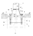
図1は、本発明にかかる金属管柱の基部構造の1例を示す縦断面図である。 FIG. 1 is a longitudinal sectional view showing an example of a base structure of a metal tube column according to the present invention.
4本のアンカーボルト6の一端部を基礎4の中に埋め込み、かつ他端部を基礎天端5から上方に突出させてなる状態で、基礎天端5が地面GLと同レベルにコンクリートの基礎4を形成する。アンカーボルト6は基礎4中でアンカーボルト連結材11によってお互いに固定されている。基礎天端5から上方に突出させたアンカーボルト6のそれぞれに、基礎天端5から距離を置いてベースプレート載置用ナット9を2個ねじ込み、この上に柱脚金物3と一体化されたベースプレート2を、ベースプレート2に穿たれたアンカーボルト挿入用孔13に位置合わせして載置する。その後、ベースプレート2から上方に突出しているアンカーボルト6に平座金8を嵌めてから締め付けナット7を2個ねじ込み、ベースプレート2を間に挟んでベースプレート載置用ナット9との間で締め付けナット7を締め付けることで、基礎天端5とベースプレート2の間に隙間を持たせた状態でベースプレート2が基礎に固定される。そして、金属管柱1がベースプレート2と一体化した柱脚金物2に取り付けられて立設される。
A concrete foundation in which one end of the four
このように、基礎天端5とベースプレート2の間に隙間を持たせているので、通気性がよく、金属管柱の管内に結露が発生しにくいだけでなく、水が金属管柱の基部に溜まりにくいから、金属管柱の下部と基部は腐食しにくくなる。
As described above, since the gap is provided between the base top 5 and the
ここでは、ベースプレート2と一体化した柱脚金物3の上端部の内側に、金属管柱1の下端を内挿し、柱脚金物3の上端と金属管柱1の外周との間及び金属管柱1の下端と柱脚金物3の内周との間に隅肉溶接Wを施すことで、金属管柱1と柱脚金物3の接合を行っている。ただし、金属管柱と柱脚金物の溶接による接合は、このような接合手順に限定されるものではなく、柱脚金物の上端部の外周に嵌合部を形成した上で金属管柱の下端をこの嵌合部に外挿し、金属管柱の下端と柱脚金物の外周との間に突合せ溶接を施すことによって行ってもよい。
Here, the lower end of the
なお、柱脚金物3とベースプレート2は中空であるから、金属管内に結露によって発生した水や管内に侵入した雨水を金属管外へ排出することができる。ベースプレート2の平面形状は、中心部が中空の4角形若しくは6角形等の多角形状又は円形である。また、金属管は、鋼管やアルミニウム管等を用いることができる。そして、その形状は、円管のほか、4角形、6角形若しくは8角形等の多角形管を用いることができる。
In addition, since the
ここでは、基礎4の中に埋め込みかつ他端部を基礎天端5から上方に突出させるアンカーボルト6を4本用いたが、その本数を格別に制限するものではなく、必要に応じて適宜増減することができる。
Here, four
また、ベースプレート載置用ナット9は、アンカーボルト1本当たり2個用いたが、1個又は3個以上用いてもよい。複数個のベースプレート載置用ナットを用いるときの合計長さを、基礎天端5とベースプレート2の隙間の長さ又はそれ以上にすれば、アンカーボルトの径と相俟って太径が形成されるので、アンカーボルトの強度を大きくすることができる。
Further, although two base
そして、締め付けナットを締め付けた後にこのナットの緩みを防止するために、締め付けナットを2個用いることがなされたが、1個の締め付けナットと緩み止め金具を用いてもよい。 Then, in order to prevent loosening of the nut after tightening the tightening nut, two tightening nuts have been used, but one tightening nut and a locking metal fitting may be used.
図2は、本発明にかかる金属管柱の基部構造の他の例を示す縦断面図である。 FIG. 2 is a longitudinal sectional view showing another example of the base structure of the metal tube pillar according to the present invention.
基礎天端5を地面GLよりも高いレベルに基礎4を形成した点と、ベースプレート2と一体化した柱脚金物3の上端部の外周に嵌合部20を形成した上で金属管柱3の下端をこの嵌合部20に外挿し、金属管柱の下端と柱脚金物の外周との間に突合せ溶接W’を施したものである点を除いて、実施例1と変わるところはない。ただし、基礎天端5が地面GLよりも高いレベルにあるため、金属管内に結露によって発生した水や管内に侵入した雨水が金属管外へ排出されるだけでなく、基礎天端上にも溜まらないようになる。
The
したがって、金属管柱の下部及び基部が常時乾燥状態に保たれるから、金属管柱の下部及び基部は腐食しにくくなる。 Therefore, since the lower part and the base part of the metal tube column are always kept in a dry state, the lower part and the base part of the metal tube column are hardly corroded.
図3は、本発明にかかる金属管柱の基部構造の他の例を示す縦断面図である。 FIG. 3 is a longitudinal sectional view showing another example of the base structure of the metal tube pillar according to the present invention.
基礎天端5を地面GLよりも低いレベルに基礎4を形成するとともにベースプレート2の上面を地面GLと同じレベルに形成した点を除いて、実施例1と変わるところはない。ただし、基礎天端5が地面GLよりも低いレベルにあるため、金属管内に結露によって発生した水や管内に侵入した雨水が金属管外へ排出されても、基礎天端上に溜まることになる。
There is no difference from the first embodiment except that the
したがって、その水はある程度、基礎4上に溜まることになるが、いずれ、側方の土壌中に吸収されたり、蒸発したりすることによって、乾燥状態になるから、金属管柱の下部及び基部は腐食しにくくなる。
Therefore, the water will accumulate to some extent on the
図4は、本発明にかかる金属管柱の基部構造の他の例を示す縦断面図である。 FIG. 4 is a longitudinal sectional view showing another example of the base structure of the metal tube pillar according to the present invention.
基礎天端5にその中央部を少し高くする傾斜をつけた基礎4を形成した点を除いて、実施例3と変わるところはない。ただし、基礎天端5にその中央部を少し高くする傾斜をつけた分、水が基礎天端5の周辺部に溜まることになる。しかし、いずれ、側方の土壌中に吸収されたり、蒸発したりすることによって、乾燥状態になるから、金属管柱の下部及び基部は腐食しにくくなる。
There is no difference from Example 3 except that a
図5は、本発明にかかる金属管柱の基部構造の他の例を示す縦断面図である。 FIG. 5 is a longitudinal sectional view showing another example of the base structure of the metal tube pillar according to the present invention.
基礎天端5を右方向から左方向に下がる傾斜をつけた基礎4を形成した点と、ベースプレート2と一体化した柱脚金物3の上端部の外周に嵌合部20を形成した上で金属管柱3の下端をこの嵌合部20に外挿し、金属管柱の下端と柱脚金物の外周との間に突合せ溶接W’を施したものである点を除いて、実施例3と変わるところはない。ただし、基礎天端5にこのような傾斜をつけた分、水が基礎天端5の左部に溜まることになる。しかし、いずれ、側方の土壌中に吸収されたり、蒸発したりすることによって、乾燥状態になるから、金属管柱の下部及び基部は腐食しにくくなる。
The base top 5 is formed with a
図6は、本発明にかかる金属管柱の基部構造の他の例を示す縦断面図である。 FIG. 6 is a longitudinal sectional view showing another example of the base structure of the metal tube pillar according to the present invention.
基礎天端5の左部と右部に凹部を形成した基礎4である点を除いて、実施例3と変わるところはない。ただし、基礎天端5の左部と右部に凹部を形成した分、水が基礎天端5の左部と右部の凹部に溜まることになる。しかし、いずれ、側方の土壌中に吸収されたり、蒸発したりすることによって、乾燥状態になるから、金属管柱の下部及び基部は腐食しにくくなる。
There is no difference from Example 3 except that the
図7は、本発明にかかる金属管柱の基部構造の他の例を示す縦断面図である。 FIG. 7 is a longitudinal sectional view showing another example of the base structure of the metal tube pillar according to the present invention.
4本のアンカーボルト6の一端部を基礎4の中に埋め込み、かつ他端部を基礎天端5から上方に突出させる状態で、基礎天端5が地面GLよりも高いレベルにコンクリートの基礎4を形成する。アンカーボルト6は基礎4中でアンカーボルト連結材11によってお互いに固定されている。基礎天端5から上方に突出させたアンカーボルト6に、緩み止めナット16をねじ込み、その後、ベースプレート載置用高ナット10をねじ込む。ただし、基礎4をコンクリートで形成する際には、緩み止めナット16の全部と高ナット10の下部が基礎内に埋め込まれるようにする。この高ナット10の上に、柱脚金物3と一体化されたベースプレート2を、ベースプレート2に穿たれたアンカーボルト挿入用孔13に位置合わせして載置する。その後、ベースプレート2から上方に突出しているアンカーボルト6に平座金8を嵌めてから締め付けナット7を2個ねじ込み、ベースプレート2を間に挟んでベースプレート載置用高ナット10との間で締め付けナット7を締め付けることで、基礎天端5とベースプレート2の間に隙間を持たせた状態でベースプレート2が基礎に固定される。そして、金属管柱1がベースプレート2と一体化した柱脚金物2に取り付けられて立設される。
The
ここでは、ベースプレート2と一体化した柱脚金物3の上端部の外周に嵌合部20を形成した上で金属管柱1の下端をこの嵌合部20に外挿し、金属管柱1の下端と柱脚金物3の外周との間に突合せ溶接W’を施すことで、金属管柱1と柱脚金物3の接合を行っている。ただし、金属管柱と柱脚金物の溶接による接合は、このような接合手順に限定されるものではなく、柱脚金物の上端部の内側に金属管柱の下端を内挿し、柱脚金物の上端と金属管柱の外周との間及び金属管柱の下端と柱脚金物の内周との間に隅肉溶接を施すことによって行ってもよい。
Here, after the
このように、アンカーボルトのネジ部の途中にねじ込まれるベースプレート載置用ナットとして高ナットを用いると、高ナットの全体とアンカーボルトとが相俟って、基礎天端5とベースプレート2の間に隙間を持たせた状態で、ベースプレートを高強度で支持することができる。
As described above, when a high nut is used as a base plate mounting nut to be screwed in the middle of the threaded portion of the anchor bolt, the entire high nut and the anchor bolt are combined to form a space between the base top 5 and the
なお、柱脚金物3とベースプレート2は中空であるから、金属管内に結露によって発生した水や管内に侵入した雨水を金属管外へ排出することができる点、ベースプレート2の平面形状は中心部が中空の4角形若しくは6角形等の多角形状又は円形とすることができる点、金属管は鋼管やアルミニウム管等を用いることができ、そして、その形状は、円管のほか、4角形、6角形若しくは8角形等の多角形管を用いることができる点などは、いずれも、実施例1と同様である。
Since the
また、基礎4の中に埋め込みかつ他端部を基礎天端5から上方に突出させるアンカーボルト6の本数は、4本に限らず、必要に応じて適宜増減することができる点、そして、締め付けナットを締め付けた後にこのナットの緩みを防止するために、締め付けナットを2個用いることに代えて、1個の締め付けナットと緩み止め金具を用いてもよい点などは、いずれも実施例1と同様である。
Further, the number of
図8は、本発明にかかる金属管柱の基部構造の他の例を示す縦断面図である。 FIG. 8 is a longitudinal sectional view showing another example of the base structure of the metal tube pillar according to the present invention.
基礎天端5を地面GLと同レベルに基礎4を形成した点と、ベースプレート2と一体化した柱脚金物3の上端部の内側に、金属管柱1の下端を内挿し、柱脚金物3の上端と金属管柱1の外周との間及び金属管柱1の下端と柱脚金物3の内周との間に隅肉溶接Wを施したものである点を除いて、実施例7と変わるところはない。
The
このように、アンカーボルトのネジ部の途中にねじ込まれるベースプレート載置用高ナットの下部の一部を基礎内に埋め込ませると、基礎天端5とベースプレート2の間に隙間を持たせた状態で、ベースプレートをより高強度で支持することができる。金属管内に結露によって発生した水や管内に侵入した雨水が金属管外へ排出されるだけでなく、基礎天端上にも溜まらず、金属管柱の下部及び基部が乾燥状態に保たれるから、金属管柱の下部及び基部は腐食しにくくなる。
Thus, when a part of the lower part of the base plate mounting high nut screwed in the middle of the threaded portion of the anchor bolt is embedded in the foundation, a gap is provided between the
図9は、本発明にかかる金属管柱の基部構造の他の例を示す縦断面図である。 FIG. 9 is a longitudinal sectional view showing another example of the base structure of the metal tube pillar according to the present invention.
基礎天端5を地面GLよりも低いレベルに基礎4を形成するとともにベースプレート2の上面を地面GLと同じレベルに形成した点を除いて、実施例8と変わるところはない。ただし、基礎天端5が地面GLよりも低いレベルにあるため、金属管内に結露によって発生した水や管内に侵入した雨水が金属管外へ排出されても、基礎天端上に溜まることになる。
There is no difference from Example 8 except that the
したがって、その水はある程度、基礎4上に溜まることになるが、いずれ、側方の土壌中に吸収されたり、蒸発したりすることによって、乾燥状態になるから、金属管柱の下部及び基部は腐食しにくくなる。
Therefore, the water will accumulate to some extent on the
図10は、本発明にかかる金属管柱の基部構造の他の例を示す縦断面図である。 FIG. 10 is a longitudinal sectional view showing another example of the base structure of the metal tube pillar according to the present invention.
4本のアンカーボルト6の一端部を基礎4の中に埋め込み、かつ他端部を基礎天端5から上方に突出させる状態で、基礎天端5が地面GLよりも高いレベルにコンクリートの基礎4を形成する。アンカーボルト6は基礎4中でアンカーボルト連結材11によってお互いに固定されている。基礎天端5から上方に突出させたアンカーボルト6に、緩み止めナット16をねじ込み、その後、ベースプレート載置用高ナット10をねじ込む。ただし、コンクリート基礎を形成する際には、緩み止めナット16の全部と高ナット10の下部が基礎内に埋め込まれるようにする。
The
この高ナット10の上に、ベースプレート2に穿たれたアンカーボルト挿入用孔13に位置合わせして、ベースプレート2を載置する。その後、ベースプレート2から上方に突出しているアンカーボルト6に平座金8を嵌めてから締め付けナット7を2個ねじ込み、ベースプレート2を間に挟んでベースプレート載置用高ナット10との間で締め付けナット7を締め付けることで、基礎天端5とベースプレート2の間に隙間を持たせた状態でベースプレート2が基礎に固定される。そして、金属管柱1がベースプレート2に取り付けられて立設される。
The
ここでは、金属管柱1はその下端部の外周に隅肉溶接Wを施すことによってベースプレート2と接合されている。さらに、三角形状のリブプレート19が金属管柱1の下部とベースプレート2の間に4枚垂直に設けられているが、5枚以上であっても構わない。
Here, the
このように、アンカーボルト6のネジ部の途中にねじ込まれるベースプレート載置用ナットとして高ナット10を用いると、高ナット10の全体とアンカーボルト6とが相俟って、基礎天端5とベースプレート2の間に隙間を持たせた状態で、ベースプレート2を高強度で支持することができる。
As described above, when the
なお、ベースプレート2はドーナツ状であるから、金属管内に結露によって発生した水や管内に侵入した雨水を金属管外へ排出することができる点、ベースプレート2の平面形状は中心部が中空の4角形若しくは6角形等の多角形状又は円形とすることができる点、金属管は鋼管やアルミニウム管等を用いることができ、そして、その形状は、円管のほか、4角形、6角形若しくは8角形等の多角形管を用いることができる点などは、いずれも、実施例1と同様である。
Since the
また、基礎4の中に埋め込みかつ他端部を基礎天端5から上方に突出させるアンカーボルト6の本数は、4本に限らず、必要に応じて適宜増減することができる点、締め付けナットを締め付けた後にこのナットの緩みを防止するために、締め付けナットを2個用いることに代えて、1個の締め付けナットと緩み止め金具を用いてもよい点などは、いずれも実施例1と同様である。
Further, the number of
図11は、本発明にかかる金属管柱の基部構造の他の例を示す縦断面図である。 FIG. 11 is a longitudinal sectional view showing another example of the base structure of the metal tube pillar according to the present invention.
金属管柱1の基部を補強するために金属管柱の下部に設けるリブプレート19をベースプレート2の下に設置した点と、基礎天端5とベースプレート2の間の隙間を大きくするために高ナット長を長くした点を除いて、実施例10と変わるところがない。
In order to reinforce the base portion of the
なお、ここでは、金属管柱1とベースプレート2との接合は、ベースプレート2の上面の金属管柱1の下端部の外周だけでなく、ベースプレート2の下面の金属管柱1の下端部の外周にも、隅肉溶接Wを施すことによってなされている。さらに、三角形状のリブプレート19が金属管柱1の下部とベースプレート2の間に4枚垂直に設けられているが、5枚以上であっても構わない。また、リブプレートは三角形状に限らず、矩形状であってもよい。
Here, the
このように、ベースプレート2の下側にリブプレート19を設けると、このリブプレート19に歩行者等がつまずいたり、衣服を引っかけたりすることがなくなる。
Thus, when the
図12は、本発明にかかる金属管柱の基部構造の他の例を示す縦断面図である。 FIG. 12 is a longitudinal sectional view showing another example of the base structure of the metal tube pillar according to the present invention.
金属管柱1の基部を補強するために金属管柱の下部に設けるリブプレート19に、アンカーボルト挿入用孔13にアンカーボルトの他端部と締め付けナット7と平座金8を収容するためのざぐり加工による開口部18を形成した点と、締め付けナットを2個用いる代わりに、1個の締め付けナット7と弛緩防止金具(図15及び図15参照)を用いた点を除いて、実施例11と変わるところがない。
A
このように、ベースプレート2に穿たれたアンカーボルト挿入用孔13にざぐり加工を施して開口部18を形成し、この開口部18にアンカーボルトの他端部と締め付けナット7を収容すると、このアンカーボルトの他端部と締め付けナット7に歩行者等がつまずいたり、衣服を引っかけたりすることがなくなる。なお、ざぐり加工による開口部に蓋をしたり、パテ等を充填したりして、開口部を埋める構造にすれば、開口部が密封されるので、雨水が浸入することはない。また、締め付けナットが人目に触れにくくなるので、人為的な悪意による締め付けナットの緩みを防止することもできる。充填材は、特に限定するものではないが、たとえば、ポリブタジエンを主成分とする弾性シール材が好ましい。
In this way, the anchor
図13は、弛緩防止金具17の一例を示しており、図12におけるアンカーボルト挿入用孔13とその周辺の部分拡大図である。(a)は上面図、そして(b)は縦断面図である。
FIG. 13 shows an example of the loosening
弛緩防止金具30は、その内面31に6角形状の締め付けナット7の外側面に嵌合する孔形状を有しており、かつその外周に凸部33を備えている。そして、その内面31が締め付け用ナット7の外側面に嵌合している。また、ざぐり加工による開口部18の側面には凹部21が設けられており、その凹部に弛緩防止金具30の凸部33を嵌合させてあり、弛緩防止金具の水平方向における回転を防止する構造となっている。ここでは、凹部21の形状は横断面が半円形状でベースプレート上面に開口した縦溝となっているが、横断面の形状はこれに限定されるものではなく、多角形状であってもよい。また、凸部33の形状も限定されるものでなく、凸部がこの凹部に拘束されて弛緩防止金具の水平方向における回転が防止できる形状であればよい。また、ここでは、ざぐり加工による開口部18に浸入した雨水を外部に排出するための排水用孔22が設置されている。排水用孔22は必ずしも必要でないが、ナット締結部の腐食防止のために設置するのが好ましい。
The loosening prevention metal fitting 30 has a hole shape that fits to the outer surface of the
ここで、弛緩防止金具30の内面31の孔と締め付け用ナット7の外側面は、互いに嵌合できる形状を有する必要があるが、締め付け用ナット7の回転が、弛緩防止金具30の内面31の孔の存在によって妨げられていればよく、嵌合時に少々の遊びが存在しても構わない。なお、弛緩防止金具30は、嵌合部に遊びの存在する方が取り付け作業が容易になるので、嵌合部にある程度の遊びが存在するような形状とするのが好ましい。
Here, the hole on the
そして、締め付け用ナット7の外側面に嵌合する弛緩防止金具30の内面31の孔は、ここでは6角形状となっているが、弛緩防止金具の内面の孔の形状に合わせた形状でよい。なお、弛緩防止金具の内面の孔の形状と、締め付け用ナットの外側面の形状は全く同じ形状である必要はなく、締め付け用ナットの回転が、ベースプレートに固定された弛緩防止金具の内面の孔によって妨げられていればよいので、締め付け用ナットが6角形状のときの弛緩防止金具の内面の孔は、その倍の12角形状であっても構わない。
And although the hole of the
さらに、ここでは、弛緩防止金具30の外周に凸部33を備え、そして、ざぐり加工による開口部18の側面には凹部21が設けられているが、この凹凸を逆にして、弛緩防止金具30の外周に凹部を備え、そして、ざぐり加工による開口部18の側面には凸部が設けられていてもよい。この場合にも、ざぐり加工による開口部18の側面の凸部に弛緩防止金具30の凹部33を嵌合させることができるので、弛緩防止金具の水平方向における回転を防止できる構造となっている。
Further, here, the
また、このように、ざぐり加工を施して開口部にナット締結部を収容した後に、その開口部に蓋をしたり、パテ等を充填したりして開口部を埋める構造にすることもできることは上述したとおりである。この場合、開口部が密封されるので、雨水が浸入することはなく、したがって、排水用孔22を設けなくてもよい。充填材は、特に限定するものではないが、たとえば、ポリブタジエンを主成分とする弾性シール材が好ましい。
In addition, in this way, it is possible to make a structure in which the opening is filled by carrying out counterboring and accommodating the nut fastening portion in the opening, and then filling the opening or filling with a putty or the like. As described above. In this case, since the opening is sealed, rainwater does not enter, and therefore the
図14は、弛緩防止金具17の他の例を示しており、図12におけるアンカーボルト挿入用孔13とその周辺の部分拡大図である。(a)は上面図、そして(b)は縦断面図である。
FIG. 14 shows another example of the relaxation preventing
図14に示す弛緩防止金物の内面31は、締め付け用ナット7の3つの角部と嵌合する形状となっている。このように、締め付け用ナット7の角部の一部が嵌合できれば、ナットの緩みを防止することができるので、弛緩防止金物の内面31の形状は、締め付け用ナットの外面形状と同じである必要はない。締め付け用ナットの外側面の少なくとも一個所に嵌合する形状を有しておればよい。
The
図15は、本発明にかかる金属管柱の基部構造の他の例を示す縦断面図である。 FIG. 15: is a longitudinal cross-sectional view which shows the other example of the base part structure of the metal pipe pillar concerning this invention.
柱脚金物3と一体化したベースプレート2に、アンカーボルト挿入用孔13にアンカーボルト6の他端部と締め付けナット7と平座金8を収容するためのざぐり加工による開口部18を形成した点と、締め付けナット7を2個用いる代わりに、1個の締め付けナット7と弛緩防止金具(図示せず)を用いた点を除いて、実施例9と変わるところがない。
The
このように、ベースプレート2に穿たれたアンカーボルト挿入用孔13にざぐり加工を施して開口部18を形成し、この開口部18にアンカーボルトの他端部と締め付けナット7を収容すると、このアンカーボルトの他端部と締め付けナット7に歩行者等がつまずいたり、衣服を引っかけたりすることがなくなる。なお、ざぐり加工による開口部に蓋をしたり、パテ等を充填したりして、開口部を埋める構造にすれば、開口部が密封されるので、雨水が浸入することはない。また、締め付けナットが人目に触れにくくなるので、人為的な悪意による締め付けナットの緩みを防止することもできる。充填材は、特に限定するものではないが、たとえば、ポリブタジエンを主成分とする弾性シール材が好ましい。
In this way, the anchor
図16は、本発明にかかる金属管柱の基部構造の他の例を示す縦断面図である。 FIG. 16: is a longitudinal cross-sectional view which shows the other example of the base part structure of the metal pipe pillar concerning this invention.
4本のアンカーボルト6の一端部を基礎4の中に埋め込み、かつ他端部を基礎天端5から上方に少しだけ突出させる状態で、基礎天端5が地面GLと同レベルにコンクリートの基礎4を形成する。アンカーボルト6は基礎4中でアンカーボルト連結材11によってお互いに固定されている。
A concrete foundation with the base top 5 at the same level as the ground GL with one end of the four
そして、基礎天端5から上方に少しだけ突出させたアンカーボルト6に、緩み止めナット16をねじ込み、その後、緩み止めナット16をねじ込んだ後のアンカーボルト6の突出部分にベースプレート載置用高ナット10を、高ナットの下部を基礎内に埋め込ませる形でねじ込む。このとき、緩み止めナット16をねじ込んだ後のアンカーボルト6の突端が高ナットの中程に位置することができるだけの長さを有する高ナット10を用いる。また、コンクリート基礎を形成する際には、緩み止めナット16の全部と高ナット10の下部が基礎内に埋め込まれるようにする。
Then, a locking
この高ナット10の上に、柱脚金物3と一体化されたベースプレート2を、ベースプレート2に穿たれた締め付けボルト挿入用孔14に位置合わせして載置する。
On the
その後、ベースプレート2の締め付けボルト挿入用孔14の上から、平座金8を介して、締め付けボルト12をベースプレート載置用高ナット10にねじ込み、ベースプレート2を間に挟んでベースプレート載置用高ナット10との間で締め付けボルト12を締め付けることで、基礎天端5とベースプレート2の間に隙間を持たせた状態でベースプレート2が基礎に固定される。そして、金属管柱1がベースプレート2と一体化した柱脚金物2に取り付けられて立設される。
Thereafter, the tightening
ここでは、ベースプレート2と一体化した柱脚金物3の上端部の内側に、金属管柱1の下端を内挿し、柱脚金物3の上端と金属管柱1の外周との間及び金属管柱1の下端と柱脚金物3の内周との間に隅肉溶接Wを施すことで、金属管柱1と柱脚金物3の接合を行っている。ただし、金属管柱と柱脚金物の溶接による接合は、このような接合手順に限定されるものではなく、柱脚金物の上端部の外周に嵌合部を形成した上で金属管柱の下端をこの嵌合部に外挿し、金属管柱の下端と柱脚金物の外周との間に突合せ溶接を施すことによって行ってもよい。
Here, the lower end of the
このように、基礎天端5からのアンカーボルト6の突出部分を短くして、この突出部分よりも全長の長いベースプレート載置用高ナット10をアンカーボルト6の突出部にねじ込んだ後に、ベースプレート2を間に挟んで締め付けボルト12をベースプレート載置用高ナット10にねじ込み、締め付けると、基礎天端5とベースプレート2の間に隙間を持たせた状態で、ベースプレート2をより高強度で支持することができる。このとき、アンカーボルト6のベースプレート2上への突出部分は形成されず、締め付けボルトの頭の部分がベースプレート2の上に出現するだけである。したがって、歩行者等がつまずいたり、衣服を引っかけたりすることは、ほとんどなくなるという利点がある。
In this way, after the protruding portion of the
なお、柱脚金物3とベースプレート2は中空であるから、金属管内に結露によって発生した水や管内に侵入した雨水を金属管外へ排出することができる点、ベースプレート2の平面形状は中心部が中空の4角形若しくは6角形等の多角形状又は円形とすることができる点、金属管は鋼管やアルミニウム管等を用いることができ、そして、その形状は、円管のほか、4角形、6角形若しくは8角形等の多角形管を用いることができる点などは、いずれも、実施例1と同様である。
Since the
また、基礎4の中に埋め込みかつ他端部を基礎天端5から上方に突出させるアンカーボルト6の本数は、4本に限らず、必要に応じて適宜増減することができる点などは、いずれも実施例1と同様である。
Further, the number of
図17は、本発明にかかる金属管柱の基部構造の他の例を示す縦断面図である。 FIG. 17 is a longitudinal sectional view showing another example of the base structure of the metal tube pillar according to the present invention.
基礎天端5を地面GLよりも高いレベルに基礎4を形成した点と、ベースプレート2と一体化した柱脚金物3の上端部の外周に嵌合部20を形成した上で金属管柱3の下端をこの嵌合部20に外挿し、金属管柱の下端と柱脚金物の外周との間に突合せ溶接W’を施したものである点を除いて、実施例14と変わるところはない。ただし、基礎天端5が地面GLよりも高いレベルにあるため、金属管内に結露によって発生した水や管内に侵入した雨水が金属管外へ排出されるだけでなく、基礎天端上にも溜まらないようになる。
The
図18は、本発明にかかる金属管柱の基部構造の他の例を示す縦断面図である。 FIG. 18 is a longitudinal sectional view showing another example of the base structure of the metal tube pillar according to the present invention.
基礎天端5を地面GLよりも低いレベルに基礎4を形成するとともにベースプレート2の上面を地面GLと同じレベルにした点を除いて、実施例14と変わるところはない。ただし、基礎天端5が地面GLよりも低いレベルにあるため、金属管内に結露によって発生した水や管内に侵入した雨水が金属管外へ排出されても、基礎天端上に溜まることになる。
There is no difference from Example 14 except that the
したがって、その水はある程度、基礎4上に溜まることになるが、いずれ、側方の土壌中に吸収されたり、蒸発したりすることによって、乾燥状態になるから、金属管柱の下部及び基部は腐食しにくくなる。
Therefore, the water will accumulate to some extent on the
図19は、本発明にかかる金属管柱の基部構造の他の例を示す縦断面図である。 FIG. 19 is a longitudinal sectional view showing another example of the base structure of the metal tube pillar according to the present invention.
4本のアンカーボルト6の一端部を基礎4の中に埋め込み、かつ他端部を基礎天端5から上方に少しだけ突出させる状態で、基礎天端5が地面GLよりも高いレベルにコンクリートの基礎4を形成する。アンカーボルト6は基礎4中でアンカーボルト連結材11によってお互いに固定されている。
With one end of the four
そして、基礎天端5から上方に少しだけ突出させたアンカーボルト6に、緩み止めナット16をねじ込み、その後、緩み止めナット16をねじ込んだ後のアンカーボルト6の突出部分にベースプレート載置用高ナット10を、高ナットの下部を基礎内に埋め込ませる形でねじ込む。このとき、緩み止めナット16をねじ込んだ後のアンカーボルト6の突端が高ナットの中程に位置することができるだけの長さを有する高ナット10を用いる。また、コンクリート基礎を形成する際には、緩み止めナット16の全部と高ナット10の下部が基礎内に埋め込まれるようにする。
Then, a locking
この高ナット10の上に、ベースプレート2に穿たれた締め付けボルト挿入用孔14に位置合わせして、ベースプレート2を載置する。その後、ベースプレート2の締め付けボルト挿入用孔14の上から、平座金8を介して、締め付けボルト12をベースプレート載置用高ナット10にねじ込み、ベースプレート2を間に挟んでベースプレート載置用高ナット10との間で締め付けボルト12を締め付けることで、基礎天端5とベースプレート2の間に隙間を持たせた状態でベースプレート2が基礎に固定される。そして、金属管柱1がベースプレート2と一体化した柱脚金物2に取り付けられて立設される。
The
ここでは、金属管柱1はその下端部の外周に隅肉溶接Wを施すことによってベースプレート2と接合されている。さらに、三角形状のリブプレート19が金属管柱1の下部とベースプレート2の間に4枚垂直に設けられているが、5枚以上であっても構わない。
Here, the
このように、基礎天端5からのアンカーボルト6の突出部分を短くして、この突出部分よりも全長の長いベースプレート載置用高ナット10をアンカーボルト6の突出部にねじ込んだ後に、ベースプレート2を間に挟んで締め付けボルト12をベースプレート載置用高ナット10にねじ込み、締め付けると、基礎天端5とベースプレート2の間に隙間を持たせた状態で、ベースプレート2をより高強度で支持することができる。
In this way, after the protruding portion of the
なお、ベースプレート2は中空であるから、金属管内に結露によって発生した水や管内に侵入した雨水を金属管外へ排出することができる点、ベースプレート2の平面形状は中心部が中空の4角形若しくは6角形等の多角形状又は円形とすることができる点、金属管は鋼管やアルミニウム管等を用いることができ、そして、その形状は、円管のほか、4角形、6角形若しくは8角形等の多角形管を用いることができる点などは、いずれも、実施例10と同様である。
Since the
また、基礎4の中に埋め込みかつ他端部を基礎天端5から上方に突出させるアンカーボルト6の本数は、4本に限らず、必要に応じて適宜増減することができる点などは、いずれも実施例10と同様である。
Further, the number of
図20は、本発明にかかる金属管柱の基部構造の他の例を示す縦断面図である。 FIG. 20 is a longitudinal sectional view showing another example of the base structure of the metal tube pillar according to the present invention.
金属管柱1の基部を補強するために金属管柱の下部に設けるリブプレート19をベースプレート2の下に設置した点と、基礎天端5とベースプレート2の間の隙間を大きくするために高ナット長を長くした点を除いて、実施例17と変わるところがない。
In order to reinforce the base portion of the
なお、ここでは、金属管柱1とベースプレート2との接合は、ベースプレート2の上面の金属管柱1の下端部の外周だけでなく、ベースプレート2の下面の金属管柱1の下端部の外周にも、隅肉溶接Wを施すことによってなされている。さらに、三角形状のリブプレート19が金属管柱1の下部とベースプレート2の間に4枚垂直に設けられているが、5枚以上であっても構わない。また、リブプレートは三角形状に限らず、矩形状であってもよい。
Here, the
このように、ベースプレート2の下側にリブプレート19を設けると、このリブプレート19に歩行者等がつまずいたり、衣服を引っかけたりすることがなくなる。
Thus, when the
図21は、本発明にかかる金属管柱の基部構造の他の例を示す縦断面図である。 FIG. 21 is a longitudinal sectional view showing another example of the base structure of the metal tube pillar according to the present invention.
金属管柱1の基部を補強するために金属管柱の下部に設けるリブプレート19に、締め付けボルト挿入用孔14に締め付けボルト12の頭と平座金8を収容するためのざぐり加工による開口部18を形成した点と、弛緩防止金具(図15及び図15参照)を用いた点を除いて、実施例17と変わるところがない。
A
弛緩防止金具30は、実施例12で用いたものが利用できる。図13又は図14に示した弛緩防止金具30を、締め付けボルト12の外側面に嵌合させることで、実施例12と同様に、弛緩防止金具30の水平方向における回転を防止することができる。
As the relaxation preventing metal fitting 30, the one used in the twelfth embodiment can be used. By fitting the loosening prevention metal fitting 30 shown in FIG. 13 or FIG. 14 to the outer surface of the tightening
このように、ベースプレート2に穿たれた締め付けボルト挿入用孔14にざぐり加工を施して開口部18を形成し、この開口部18に締め付けボルト12の頭を収容すると、この締め付けボルト12の頭に歩行者等がつまずいたり、衣服を引っかけたりすることがなくなる。なお、ざぐり加工による開口部に蓋をしたり、パテ等を充填したりして、開口部を埋める構造にすれば、開口部が密封されるので、雨水が浸入することはない。また、締め付けボルトは人目に触れにくくなるので、人為的な悪意による締め付けボルトの緩みを防止することもできる。充填材は、特に限定するものではないが、たとえば、ポリブタジエンを主成分とする弾性シール材が好ましい。
As described above, the fastening
図22は、本発明にかかる金属管柱の基部構造の他の例を示す縦断面図である。 FIG. 22 is a longitudinal sectional view showing another example of the base structure of the metal tube pillar according to the present invention.
柱脚金物3と一体化したベースプレート2に、締め付けボルト挿入用孔14に締め付けボルト12の頭と平座金8を収容するためのざぐり加工による開口部18を形成した点と、高ナット長を短くした点を除いて、実施例16と変わるところがない。
The
弛緩防止金具30は、実施例12で用いたものが利用できる。図13又は図14に示した弛緩防止金具30を、締め付けボルト12の外側面に嵌合させることで、実施例12と同様に、弛緩防止金具30の水平方向における回転を防止することができる。
As the relaxation preventing metal fitting 30, the one used in the twelfth embodiment can be used. By fitting the loosening prevention metal fitting 30 shown in FIG. 13 or FIG. 14 to the outer surface of the tightening
このように、ベースプレート2に穿たれた締め付けボルト挿入用孔14にざぐり加工を施して開口部18を形成し、この開口部18に締め付けボルト12の頭を収容すると、この締め付けボルト12の頭に歩行者等がつまずいたり、衣服を引っかけたりすることがなくなる。なお、ざぐり加工による開口部に蓋をしたり、パテ等を充填したりして、開口部を埋める構造にすれば、開口部が密封されるので、雨水が浸入することはない。また、締め付けボルトは人目に触れにくくなるので、人為的な悪意による締め付けボルトの緩みを防止することもできる。充填材は、特に限定するものではないが、たとえば、ポリブタジエンを主成分とする弾性シール材が好ましい。
As described above, the fastening
図23は、本発明にかかる金属管柱の基部構造の他の例を示す縦断面図である。 FIG. 23 is a longitudinal sectional view showing another example of the base structure of the metal tube pillar according to the present invention.
基礎天端5を右方向から左方向に下がる傾斜をつけた基礎4を形成した点及び高ナット長を長くした点を除いて、実施例20と変わるところはない。ただし、基礎天端5にこのような傾斜をつけた分、水が基礎天端5の左部に溜まることになる。しかし、いずれ、側方の土壌中に吸収されたり、蒸発したりすることによって、乾燥状態になるから、金属管柱の下部及び基部は腐食しにくくなる。
There is no difference from Example 20 except that the
図24は、本発明にかかる金属管柱の基部構造の他の例を示す縦断面図である。 FIG. 24 is a longitudinal sectional view showing another example of the base structure of the metal tube pillar according to the present invention.
基礎天端5の左部と右部に凹部を有する基礎4を形成した点及びベースプレート2と一体化した柱脚金物3の上端部の外周に嵌合部20を形成した上で金属管柱3の下端をこの嵌合部20に外挿し、金属管柱の下端と柱脚金物の外周との間に突き合せ溶接W’を施したものである点を除いて、実施例20と変わるところはない。
The
ただし、基礎天端5の左部と右部に凹部を形成した分、水が基礎天端5の左部と右部の凹部に溜まることになる。しかし、いずれ、側方の土壌中に吸収されたり、蒸発したりすることによって、乾燥状態になるから、金属管柱の下部及び基部は腐食しにくくなる。
However, since the concave portions are formed in the left and right portions of the base
図25は、本発明にかかる金属管柱の基部構造の他の例を示す縦断面図である。 FIG. 25 is a longitudinal sectional view showing another example of the base structure of the metal tube pillar according to the present invention.
本実施例は、照明柱、信号柱や標識柱等を建て替える際に、既設基礎24を利用して、金属管柱の基部構造を新たに形成しようとするものである。
In the present embodiment, when rebuilding an illumination pillar, a signal pillar, a sign pillar, etc., an existing
既設基礎24は、既設基礎天端15が地面GLよりも低いレベルにあって、4本の既設アンカーボルト26は既設基礎24中でアンカーボルト連結材11によってお互いに固定されており、既設アンカーボルト26の一端部が既設基礎24の中に埋め込まれ、かつその他端部が既設基礎天端15から上方に突出した状態にある。この既設基礎24の上に、コンクリートを流し込んで、新たに新設基礎天端25を有する新設基礎27を形成しようとするものである。
The existing
ここでは、既設基礎24内に一端が埋め込まれている既設アンカーボルト26の他端部が、既設基礎天端15から上方に少しだけ突出させたアンカーボルト6に、緩み止めナット16をねじ込み、さらにベースプレート載置用高ナット10をねじ込む。このとき、緩み止めナット16をねじ込んだ後のアンカーボルト6の突端が高ナットの中程に位置することができるだけの長さを有する高ナット10を用いる。
Here, the other end portion of the existing
その後、既設基礎天端15の上にコンクリートを流し込んで、新設基礎天端25のレベルが高ナット10の中程に位置するように新設基礎27を形成する。
Thereafter, concrete is poured onto the existing foundation
そして、この高ナット10の上に柱脚金物3と一体化されたベースプレート2を、ベースプレート2に穿たれた締め付けボルト挿入用孔14に位置合わせして載置する。その後、ベースプレート2の締め付けボルト挿入用孔14の上から、平座金8を介して、締め付けボルト12をベースプレート載置用高ナット10にねじ込み、ベースプレート2を間に挟んでベースプレート載置用高ナット10との間で締め付けボルト12を締め付けることで、新設基礎天端15とベースプレート2の間に隙間を持たせた状態でベースプレート2が基礎に固定される。そして、金属管柱1がベースプレート2と一体化した柱脚金物2に取り付けられて立設される。
Then, on the
ここでは、ベースプレート2と一体化した柱脚金物3の上端部の内側に、金属管柱1の下端を内挿し、柱脚金物3の上端と金属管柱1の外周との間及び金属管柱1の下端と柱脚金物3の内周との間に隅肉溶接Wを施すことで、金属管柱1と柱脚金物3の接合を行っている。ただし、金属管柱と柱脚金物の溶接による接合は、このような接合手順に限定されるものではなく、柱脚金物の上端部の外周に嵌合部を形成した上で金属管柱の下端をこの嵌合部に外挿し、金属管柱の下端と柱脚金物の外周との間に突合せ溶接を施すことによって行ってもよい。
Here, the lower end of the
このように、本発明は、既設基礎24を利用して、新設基礎天端25とベースプレート2の間に隙間を持たせた状態で、ベースプレート2をより高強度で支持することができる金属管柱の基部構造を新たに形成することができる。また、このとき、アンカーボルト6のベースプレート2上への突出部分は形成されず、締め付けボルトの頭の部分がベースプレート2の上に出現するだけである。したがって、歩行者等がつまずいたり、衣服を引っかけたりすることは、ほとんどなくなるという利点がある。
As described above, the present invention uses the existing
なお、柱脚金物3とベースプレート2は中空であるから、金属管内に結露によって発生した水や管内に侵入した雨水を金属管外へ排出することができる点、ベースプレート2の平面形状は中心部が中空の4角形若しくは6角形等の多角形状又は円形とすることができる点、金属管は鋼管やアルミニウム管等を用いることができ、そして、その形状は、円管のほか、4角形、6角形若しくは8角形等の多角形管を用いることができる点などは、いずれも、実施例1と同様である。
Since the
また、既設基礎24の中に埋め込みかつ他端部を既設基礎天端15から上方に突出させるアンカーボルト6の本数は、4本に限らず、必要に応じて適宜増減することができる点などは、いずれも実施例1と同様である。
Further, the number of
図26は、本発明にかかる金属管柱の基部構造の他の例を示す縦断面図である。 FIG. 26 is a longitudinal sectional view showing another example of the base structure of the metal tube pillar according to the present invention.
柱脚金物3と一体化したベースプレート2に、締め付けボルト挿入用孔14に締め付けボルト12の頭と平座金8を収容するためのざぐり加工による開口部18を形成した点と、高ナット長を短くした点を除いて、実施例23と変わるところがない。
The
弛緩防止金具30は、実施例12で用いたものが利用できる。図13又は図14に示した弛緩防止金具30を、締め付けボルト12の外側面に嵌合させることで、実施例12と同様に、弛緩防止金具30の水平方向における回転を防止することができる。
As the relaxation preventing metal fitting 30, the one used in the twelfth embodiment can be used. By fitting the loosening prevention metal fitting 30 shown in FIG. 13 or FIG. 14 to the outer surface of the tightening
このように、ベースプレート2に穿たれた締め付けボルト挿入用孔14にざぐり加工を施して開口部18を形成し、この開口部18に締め付けボルト12の頭を収容すると、この締め付けボルト12の頭に歩行者等がつまずいたり、衣服を引っかけたりすることがなくなる。なお、ざぐり加工による開口部に蓋をしたり、パテ等を充填したりして、開口部を埋める構造にすれば、開口部が密封されるので、雨水が浸入することはない。また、締め付けボルトは人目に触れにくくなるので、人為的な悪意による締め付けボルトの緩みを防止することもできる。充填材は、特に限定するものではないが、たとえば、ポリブタジエンを主成分とする弾性シール材が好ましい。
As described above, the fastening
本発明に係る金属管柱の基部構造は、基礎天端とベースプレートの間に隙間を持たせているので、通気性がよく、管内に結露が発生しにくいだけでなく、水が金属管柱の基部に溜まりにくい。したがって、金属管柱の下部及び基部の腐食環境を改善することができ、もって、金属管の耐久性を向上させることができる。 The base structure of the metal tube pillar according to the present invention has a gap between the top of the foundation and the base plate, so that air permeability is good and condensation is not easily generated in the tube, and water is not generated in the metal tube pillar. It is difficult to collect at the base. Therefore, the corrosive environment of the lower part and the base part of the metal pipe column can be improved, and the durability of the metal pipe can be improved.
1 金属管柱
2 ベースプレート
3 柱脚金物
4 基礎
5 基礎天端
6 アンカーボルト
7 締め付けナット
8 平座金
9 載置用ナット
10 載置用高ナット
11 アンカーボルト連結材
12 締め付けボルト
13 アンカーボルト挿入用孔
14 締め付けボルト挿入用孔
15 既設基礎天端
16 緩み止めナット
18 ざぐり加工による開口部
19 リブプレート
20 嵌合部
21 ざぐり加工による開口部の側面に設けられた凹部
22 排水用孔
24 既設基礎
25 新設基礎天端
26 既設アンカーボルト
27 新設基礎
30 弛緩防止金具
31 弛緩防止金具の内面
32 弛緩防止金具の固定ボルト
33 弛緩防止金具の延長部の凸部
GL 地面
W 隅肉溶接
W’ 突合せ溶接
DESCRIPTION OF
Claims (9)
The base structure of the metal tube pillar according to any one of claims 1 to 8, wherein the base top end has a slope.
Priority Applications (1)
| Application Number | Priority Date | Filing Date | Title |
|---|---|---|---|
| JP2006205480A JP4971712B2 (en) | 2006-07-28 | 2006-07-28 | Base structure of metal tube column |
Applications Claiming Priority (1)
| Application Number | Priority Date | Filing Date | Title |
|---|---|---|---|
| JP2006205480A JP4971712B2 (en) | 2006-07-28 | 2006-07-28 | Base structure of metal tube column |
Publications (2)
| Publication Number | Publication Date |
|---|---|
| JP2008031711A true JP2008031711A (en) | 2008-02-14 |
| JP4971712B2 JP4971712B2 (en) | 2012-07-11 |
Family
ID=39121439
Family Applications (1)
| Application Number | Title | Priority Date | Filing Date |
|---|---|---|---|
| JP2006205480A Active JP4971712B2 (en) | 2006-07-28 | 2006-07-28 | Base structure of metal tube column |
Country Status (1)
| Country | Link |
|---|---|
| JP (1) | JP4971712B2 (en) |
Cited By (7)
| Publication number | Priority date | Publication date | Assignee | Title |
|---|---|---|---|---|
| WO2011051550A1 (en) * | 2009-10-29 | 2011-05-05 | Peikko Group Oy | Arrangement for foundations of mast-like structures |
| KR101354455B1 (en) * | 2013-03-06 | 2014-01-24 | 최승용 | In-ground supporting structure of a post |
| JP2015071886A (en) * | 2013-10-02 | 2015-04-16 | 株式会社竹中工務店 | Building structure |
| JP5907447B1 (en) * | 2015-07-15 | 2016-04-26 | 修隆 比屋根 | Steel column base |
| CN107780342A (en) * | 2017-10-16 | 2018-03-09 | 中铁十局集团第五工程有限公司 | A kind of construction method of contact net bolt embedded part fixing device |
| CN107882054A (en) * | 2017-10-12 | 2018-04-06 | 新疆金风科技股份有限公司 | The structure and method of wind power generating set crab-bolt sealing corrosion |
| JP2020051061A (en) * | 2018-09-25 | 2020-04-02 | 日之出水道機器株式会社 | Instrument mounting support |
Citations (7)
| Publication number | Priority date | Publication date | Assignee | Title |
|---|---|---|---|---|
| JPS5419504U (en) * | 1977-07-11 | 1979-02-08 | ||
| JPS54131309U (en) * | 1978-03-02 | 1979-09-12 | ||
| JPS55172440U (en) * | 1979-05-31 | 1980-12-10 | ||
| JPH10299081A (en) * | 1997-04-21 | 1998-11-10 | Nobuyoshi Yashima | Steel column base joining method |
| JP2002004421A (en) * | 2000-06-20 | 2002-01-09 | Sumitomo Metal Ind Ltd | Fixed part of exposed column base |
| JP2003293617A (en) * | 2003-03-17 | 2003-10-15 | Sumitomo Metal Steel Products Inc | Column base hardware for steel pipe column |
| JP2004137780A (en) * | 2002-10-18 | 2004-05-13 | Maruichi Steel Tube Ltd | Fixing structure and fixing method of steel pipe pole by anchor |
-
2006
- 2006-07-28 JP JP2006205480A patent/JP4971712B2/en active Active
Patent Citations (7)
| Publication number | Priority date | Publication date | Assignee | Title |
|---|---|---|---|---|
| JPS5419504U (en) * | 1977-07-11 | 1979-02-08 | ||
| JPS54131309U (en) * | 1978-03-02 | 1979-09-12 | ||
| JPS55172440U (en) * | 1979-05-31 | 1980-12-10 | ||
| JPH10299081A (en) * | 1997-04-21 | 1998-11-10 | Nobuyoshi Yashima | Steel column base joining method |
| JP2002004421A (en) * | 2000-06-20 | 2002-01-09 | Sumitomo Metal Ind Ltd | Fixed part of exposed column base |
| JP2004137780A (en) * | 2002-10-18 | 2004-05-13 | Maruichi Steel Tube Ltd | Fixing structure and fixing method of steel pipe pole by anchor |
| JP2003293617A (en) * | 2003-03-17 | 2003-10-15 | Sumitomo Metal Steel Products Inc | Column base hardware for steel pipe column |
Cited By (9)
| Publication number | Priority date | Publication date | Assignee | Title |
|---|---|---|---|---|
| WO2011051550A1 (en) * | 2009-10-29 | 2011-05-05 | Peikko Group Oy | Arrangement for foundations of mast-like structures |
| KR101354455B1 (en) * | 2013-03-06 | 2014-01-24 | 최승용 | In-ground supporting structure of a post |
| JP2015071886A (en) * | 2013-10-02 | 2015-04-16 | 株式会社竹中工務店 | Building structure |
| JP5907447B1 (en) * | 2015-07-15 | 2016-04-26 | 修隆 比屋根 | Steel column base |
| JP2017020312A (en) * | 2015-07-15 | 2017-01-26 | 修隆 比屋根 | Steel column leg |
| CN107882054A (en) * | 2017-10-12 | 2018-04-06 | 新疆金风科技股份有限公司 | The structure and method of wind power generating set crab-bolt sealing corrosion |
| CN107780342A (en) * | 2017-10-16 | 2018-03-09 | 中铁十局集团第五工程有限公司 | A kind of construction method of contact net bolt embedded part fixing device |
| JP2020051061A (en) * | 2018-09-25 | 2020-04-02 | 日之出水道機器株式会社 | Instrument mounting support |
| JP7127778B2 (en) | 2018-09-25 | 2022-08-30 | 日之出水道機器株式会社 | Fixture mounting strut |
Also Published As
| Publication number | Publication date |
|---|---|
| JP4971712B2 (en) | 2012-07-11 |
Similar Documents
| Publication | Publication Date | Title |
|---|---|---|
| JP4971712B2 (en) | Base structure of metal tube column | |
| KR101077238B1 (en) | Post foundation and constructing method using the same | |
| JP5037864B2 (en) | Base structure of metal tube column | |
| KR200443819Y1 (en) | Installation structure of facilities post | |
| BR112021003957A2 (en) | Combined anchor and fixture mount for anchoring an object to a concrete structure, anchor deck mount system for anchoring an object to a structure, anchor deck mount, and method for anchoring an object to a concrete structure | |
| JP5061260B1 (en) | Existing steel pipe column reinforcement and its construction method | |
| KR100520890B1 (en) | Handing facility of underground parking lot for appartment house | |
| JP5816637B2 (en) | How to install the handrail support | |
| KR101044022B1 (en) | Supporting structure | |
| JP4768762B2 (en) | Seismic masonry structure | |
| JP4698661B2 (en) | Concrete block for standing upright | |
| KR200223680Y1 (en) | Railing post provided with a single type anchor plate | |
| KR100750345B1 (en) | Control valve manhole for tap water | |
| KR200440141Y1 (en) | Street light pillar | |
| KR101636216B1 (en) | Foundation structure for pillar | |
| JP2010048041A (en) | Device for mounting handrail support | |
| KR102540716B1 (en) | Deck road using joists that can be reused without damage | |
| KR101389734B1 (en) | Method for repairing and reinforcing concrete structure by using anchor bolts having a drain hole therein | |
| KR20120003634U (en) | Erosiom Shield a nut as bolt cap | |
| JP2004137780A (en) | Fixing structure and fixing method of steel pipe pole by anchor | |
| KR100962318B1 (en) | Pole supporter of road lighter | |
| RU2515755C1 (en) | Pressing bracket and method of its use (versions) | |
| KR100969410B1 (en) | Street lighting pole and foundation structure for installing poles | |
| JP5485768B2 (en) | Guard fence and repair method of guard fence | |
| KR200372217Y1 (en) | Street lamppost |
Legal Events
| Date | Code | Title | Description |
|---|---|---|---|
| A621 | Written request for application examination |
Free format text: JAPANESE INTERMEDIATE CODE: A621 Effective date: 20090507 |
|
| A977 | Report on retrieval |
Free format text: JAPANESE INTERMEDIATE CODE: A971007 Effective date: 20110922 |
|
| A131 | Notification of reasons for refusal |
Free format text: JAPANESE INTERMEDIATE CODE: A131 Effective date: 20110927 |
|
| A521 | Written amendment |
Free format text: JAPANESE INTERMEDIATE CODE: A523 Effective date: 20111025 |
|
| TRDD | Decision of grant or rejection written | ||
| A01 | Written decision to grant a patent or to grant a registration (utility model) |
Free format text: JAPANESE INTERMEDIATE CODE: A01 Effective date: 20120403 |
|
| A01 | Written decision to grant a patent or to grant a registration (utility model) |
Free format text: JAPANESE INTERMEDIATE CODE: A01 |
|
| A61 | First payment of annual fees (during grant procedure) |
Free format text: JAPANESE INTERMEDIATE CODE: A61 Effective date: 20120406 |
|
| FPAY | Renewal fee payment (event date is renewal date of database) |
Free format text: PAYMENT UNTIL: 20150413 Year of fee payment: 3 |
|
| R150 | Certificate of patent or registration of utility model |
Free format text: JAPANESE INTERMEDIATE CODE: R150 |