JP2008025096A - Framework-furring strip integrated structure of steel-frame building - Google Patents
Framework-furring strip integrated structure of steel-frame building Download PDFInfo
- Publication number
- JP2008025096A JP2008025096A JP2006195120A JP2006195120A JP2008025096A JP 2008025096 A JP2008025096 A JP 2008025096A JP 2006195120 A JP2006195120 A JP 2006195120A JP 2006195120 A JP2006195120 A JP 2006195120A JP 2008025096 A JP2008025096 A JP 2008025096A
- Authority
- JP
- Japan
- Prior art keywords
- steel
- brace
- pair
- trunk
- frame
- Prior art date
- Legal status (The legal status is an assumption and is not a legal conclusion. Google has not performed a legal analysis and makes no representation as to the accuracy of the status listed.)
- Pending
Links
Images


Abstract
Description
本発明は、鉄骨造建築物の内外壁パネルの取付けに好適な骨組胴縁一体化構造に関するものである。 The present invention relates to a frame trunk integrated structure suitable for mounting inner and outer wall panels of a steel structure building.
従来、鉄骨造建築物にあっては、図8に示すように柱や梁等の構造部材が軸組構造として構築され、鉄骨材からなる一対の柱51,52と鉄骨材からなる一対の梁53,54とで形成される空間内に、2本のブレース(筋違い)55,56が交差配設されている。ブレース55,56は通常ターンバックル付のものが用いられ、組立調整の容易化が図られている。
Conventionally, in a steel structure building, as shown in FIG. 8, structural members such as columns and beams are constructed as a frame structure, and a pair of
ここで、一対の柱51,52と一対の梁53,54とで形成される空間内にブレース55,56を配設すると、該空間内に内外壁パネルを取付けるための胴縁を配設することが困難となる。しかし、鉄骨造建築物にあっては、地震等に対する耐震強度を確保するためにブレースを配設することが構造上不可欠であり、ブレースを省略することはできない。
Here, when the
上記従来の鉄骨造骨組構造にあっては、内外壁パネルを取付けるための胴縁を一対の柱と一対の梁とで形成される空間内に配設することは困難なことから、通常、図9に示すように胴縁57,58を柱の内面上と外面上に別々に取付けている。ここで、図9は図8中のE−E矢視図に相当するものである。しかし、このように胴縁57,58を柱51,52の内面上および外面上に別々に取付けると、室内の有効床面積の減少を招くという問題がある。そこで、図10に示すように内外壁パネルを取付ける胴縁59,60を無理して一対の柱51,52と一対の梁53,54とで形成される空間内に配設している例もある。
In the conventional steel frame structure described above, it is difficult to dispose the trunk edge for attaching the inner and outer wall panels in the space formed by the pair of columns and the pair of beams. As shown in FIG. 9, the body edges 57 and 58 are separately attached on the inner surface and the outer surface of the column. Here, FIG. 9 corresponds to an EE arrow view in FIG. However, if the trunk edges 57 and 58 are separately mounted on the inner and outer surfaces of the
また、戸建て住宅等の鉄骨造建築物においては、工場で製作した外壁パネルを建設現場に搬入し、現場で建方した柱、梁、ブレース等で構成される鉄骨造骨組構造に組み込み、一体化する場合もある(例えば、特許文献1参照)。
しかし、上述した図9に示す胴縁の取付け構造では、室内の有効床面積が減少するばかりでなく、内外壁パネルを取付ける胴縁を別々に配設する必要があるため、工事期間が長くなり、建築コストの上昇を招くという問題があった。 However, in the above-described mounting structure of the trunk edge shown in FIG. 9, not only the effective floor area in the room is reduced, but also the trunk edge for mounting the inner and outer wall panels needs to be separately provided, so the construction period becomes longer. There was a problem that the construction cost increased.
また、上述した図10に示す胴縁の取付け構造では、室内の有効床面積が減少することは回避できるものの、胴縁のサイズが極端に細くなってしまうことから十分な強度が得られないという問題があった。また、内外壁パネルを取付ける胴縁を別々に配設する必要があるため工事期間が長くなり、建築コストの上昇を招くという図9に示す胴縁の取付け構造と同様な問題があった。 In addition, in the case of the trunk edge mounting structure shown in FIG. 10 described above, it is possible to avoid a reduction in the effective floor area of the room, but it is impossible to obtain sufficient strength because the size of the trunk edge becomes extremely thin. There was a problem. Further, since it is necessary to separately arrange the barrel edges for attaching the inner and outer wall panels, the construction period becomes longer, and there is a problem similar to the barrel edge mounting structure shown in FIG.
さらに、特許文献1に記載された鉄骨造骨組構造であっても、内壁パネルと外壁パネルとの間隔は柱の太さ以上となってしまい、建物総床面積に対する有効床面積が減少することは避けられなかった。
Furthermore, even in the steel frame structure described in
本発明は上記の事情に鑑みてなされたものであり、耐震強度を確保するために不可欠なブレースを配設すると共に、内外壁パネルを取付けるための胴縁を一対の柱と一対の梁とで形成される空間内に配設して室内の有効床面積を十分確保しつつ工期短縮を可能とし、併せて建築コストの低減も期待できる鉄骨造建築物の骨組胴縁一体化構造を提供することを課題とする。 The present invention has been made in view of the above circumstances, and a brace that is indispensable for securing seismic strength is disposed, and a trunk edge for attaching the inner and outer wall panels is formed by a pair of columns and a pair of beams. To provide an integrated structure for the frame trunk edge of a steel structure that can be arranged in the space to be formed, shorten the construction period while ensuring a sufficient effective floor area in the room, and at the same time reduce the construction cost. Is an issue.
請求項1記載の発明は、鉄骨材からなる一対の柱と鉄骨材からなる一対の梁とで形成される空間内に、鉄骨材からなるブレースと胴縁とを配設し、前記胴縁の一端を前記ブレースに固定すると共に他端を前記柱または梁に固定したことを特徴とする鉄骨造建築物の骨組胴縁一体化構造である。 According to the first aspect of the present invention, a brace made of a steel frame and a trunk edge are disposed in a space formed by a pair of columns made of a steel frame and a pair of beams made of a steel frame. One structure is fixed to the brace, and the other is fixed to the column or beam.
請求項2記載の発明は、鉄骨材からなる一対の柱と鉄骨材からなる一対の梁とで形成される異なる空間内に、互いに配設方向が異なるブレースと胴縁を配設し、前記胴縁の一端を前記ブレースに固定すると共に他端を前記柱または梁に固定したことを特徴とする鉄骨造建築物の骨組胴縁一体化構造である。 According to a second aspect of the present invention, in the different spaces formed by the pair of columns made of steel frame and the pair of beams made of steel frame, braces and trunk edges having different arrangement directions are arranged, and the cylinder The frame body edge integrated structure of the steel structure building, wherein one end of the edge is fixed to the brace and the other end is fixed to the column or beam.
請求項3記載の発明は、請求項1または2記載の鉄骨造建築物の骨組胴縁一体化構造において、前記柱と前記ブレースと前記胴縁の幅寸法を同一としたことを特徴とするものである。 A third aspect of the present invention is the frame trunk edge integrated structure of the steel structure according to the first or second aspect, wherein the pillars, the braces, and the width of the trunk edge have the same width. It is.
請求項4記載の発明は、請求項1〜3のいずれか1項に記載の鉄骨造建築物の骨組胴縁一体化構造において、前記柱が角形鋼管からなることを特徴とするものである。 A fourth aspect of the present invention is the frame trunk integrated structure of a steel structure according to any one of the first to third aspects, wherein the column is formed of a square steel pipe.
請求項5記載の発明は、請求項1〜4のいずれか1項に記載の鉄骨造建築物の骨組胴縁一体化構造において、前記ブレースが角形鋼管からなることを特徴とするものである。
The invention according to
請求項6記載の発明は、請求項1〜5のいずれか1項に記載の鉄骨造建築物の骨組胴縁一体化構造において、前記胴縁が建築用鋼製下地材からなることを特徴とするものである。
The invention according to
請求項7記載の発明は、請求項1〜6のいずれか1項に記載の鉄骨造建築物の骨組胴縁一体化構造において、前記胴縁の一端をブレースに固定する固定材として薄肉溝形鋼を用いたことを特徴とするものである。 A seventh aspect of the present invention is the integrated structure of the frame trunk edge of the steel structure according to any one of the first to sixth aspects, wherein a thin groove is used as a fixing member for fixing one end of the trunk edge to the brace. It is characterized by using steel.
請求項1記載の鉄骨造建築物の骨組胴縁一体化構造によれば、一対の柱と一対の梁とで形成される空間内にブレースと胴縁とを配設し、これらの部材を一体として構成したので、建築物の耐震強度を確保しつつ室内の有効面積を十分確保できる。
According to the frame trunk integrated structure of a steel structure according to
請求項2記載の鉄骨造建築物の骨組胴縁一体化構造によれば、請求項1記載の発明が奏する効果に加えて、異なる方向からの外力に対しても十分な耐震強度を確保できる。
According to the integrated structure of the frame body edge of the steel structure according to
請求項3記載の鉄骨造建築物の骨組胴縁一体化構造によれば、内外壁パネルを取付ける胴縁の内外面と柱およびブレースの内外面とが同一平面を形成することから、内外壁パネルの取付けが容易になる。
According to the frame body frame integrated structure of a steel structure building according to
請求項4記載の鉄骨造建築物の骨組胴縁一体化構造によれば、柱として規格化された角形鋼管を用いることで工期短縮と建築コストの低減を図ることができる。
According to the frame body edge integrated structure of the steel structure building according to
請求項5記載の鉄骨造建築物の骨組胴縁一体化構造によれば、ブレースとして規格化された角形鋼管を用いることで工期短縮と建築コストの低減を図ることができる。
According to the frame body edge integrated structure of a steel structure according to
請求項6記載の鉄骨造建築物の骨組胴縁一体化構造によれば、胴縁として規格化された建築用鋼製下地材を用いることで工期短縮と建築コストの低減を図ることができる。
According to the integrated structure of the frame trunk edge of the steel structure according to
請求項7記載の鉄骨造建築物の骨組胴縁一体化構造によれば、胴縁の内外面とブレースの内外面との段差を極力小さく抑制することができる。
According to the integrated structure of the frame trunk edge of the steel structure according to
以下、本発明を実施するための形態について図面を参照しながら説明する。図1は本発明に係る鉄骨造建築物の骨組胴縁一体化構造の第1実施例を示すものである。本実施例の建物は2階建てであり、中央の柱1より右側部分は省略して左側部分だけを示している。本発明の要旨である骨組胴縁一体化構造については、1階部分と2階部分に違いがないことから、以下2階部分に基づいて説明する。
Hereinafter, embodiments for carrying out the present invention will be described with reference to the drawings. FIG. 1 shows a first embodiment of a frame body edge integrated structure of a steel structure building according to the present invention. The building of the present embodiment is a two-story building, and the right side portion is omitted from the
鉄骨材からなる一対の柱2,3と鉄骨材からなる一対の梁4,5とで形成される空間内に、鉄骨材からなるブレース6と胴縁7〜12とを配設している。ここで、2階部分に関して言えば、一対の梁は2階の床板を支持する梁5と屋根部材を支持する上部斜梁4とから構成される。そして、前記空間内にはブレース6が1本だけ配設される。また、前記空間に隣接する一対の柱1,2と一対の梁4,5とで形成される他の空間内にも1本のブレース13と複数の胴縁14〜19が配設される。このように一対の柱と一対の梁とで形成される隣接する2つの空間内に配設方向を異にするブレースを各1本だけ配設するのが本発明の特色である。
In a space formed by a pair of
図2は、図1中のA−A矢視図であり、柱2と縦胴縁12,16を含む水平断面を示している。本実施例は一般住宅用建築物であり、柱2の部材として100mm×100mm×3.2mm の角形鋼管を使用している。すなわち、一辺の外形寸法が100mm の正方形断面で、肉厚が3.2mmの角形鋼管を使用している。また、胴縁12,16の材料には100mm×45mm×10mm×0.8mmの建築用鋼製下地材(スタッド)を使用している。すなわち、肉厚0.8mmの建築用鋼製下地材である。このように薄肉軽量な建築用鋼製下地材を使用することができるのは、胴縁7〜12,14〜19には壁パネル(図示省略)が取付けられるだけであり、胴縁は強度部材ではないからである。なお、柱2の両側にも胴縁12,16と同一寸法の100mm×45mm×10mm×0.8mm の建築用鋼製下地材20,21が溶接等によって固着され、胴縁と同様の機能を果たす。
FIG. 2 is an AA arrow view in FIG. 1 and shows a horizontal cross section including the
上述したような断面寸法を有する柱2と胴縁12,16を使用すると、柱2と胴縁12,16の内外面を同一平面として構成できる利点がある。すなわち、柱断面の幅寸法および胴縁断面の幅寸法はともに100mmであり、柱2と胴縁12,16の内外面を同一平面とすることができる。その結果、内外壁パネルを共通の胴縁に対して内外面から取付けることができ、内外壁パネルの間隔を柱2および胴縁12,16の幅寸法と同じにできる。したがって、柱型が室内外に突出することがない。
When the
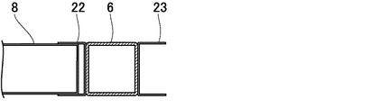
図3は、図1中のB−B矢視図であり、ブレース6の断面を示している。本実施例ではブレース6部材も柱2部材と同一断面形状のものを使用している。すなわち、ブレース6部材は100mm×100mm×3.2mmの角形鋼管を使用している。また、ブレース6の両側面には胴縁8との結合を容易にするため、固定材たるランナー22,23として102mm×40mm×0.8mm の薄肉軽量な溝形鋼を溶接等により固着している。このような寸法を有する溝形鋼を使用することにより、該溝形鋼の内幅寸法は100.4mmとなり、外幅寸法が100mmである100mm×45mm×10mm×0.8mmの胴縁たる建築用鋼製下地材8をそのまま組み込んで溶接等によって結合することができる。その結果、厳密に言えばランナー22,23の幅の外面は、ブレース6および胴縁8の幅の外面より0.8mmだけ突出することになるが、その値はごく僅かであることから内外壁パネルの取付けに際して実害はなく、ランナー22,23、ブレース6、胴縁8の内外面は実質的に同一平面として取り扱うことができる。
FIG. 3 is a BB arrow view in FIG. 1 and shows a cross-section of the
図4は、図1中のC−C矢視図であり、上部斜梁4の断面を示している。上部斜梁4には一般的な構造用形鋼であるH形鋼が用いられる。H形鋼の下面には胴縁8との結合を容易にするため、固定材たるランナー24として102mm×40mm×0.8mm の薄肉軽量な溝形鋼が固着される。また、同様にして2階床板を支持する梁5の上面にも胴縁との結合を容易にするためランナー25として102mm×40mm×0.8mm の薄肉軽量な溝形鋼が固着される。ランナー22〜25としてこのような断面寸法を有する溝形鋼を使用することにより、断面の外幅寸法が100mmである100mm×45mm×10mm×0.8mmの胴縁たる建築用鋼製下地材をそのまま組み込んで溶接等によって結合することができる。その結果、上述したブレース6部材における結合と同様にして、ランナー22〜25、梁4,5、胴縁7〜12の内外面を実質的に同一平面として取り扱うことができるようになる。
FIG. 4 is a cross-sectional view taken along the line CC in FIG. 1 and shows a cross section of the
そして、溶接等により胴縁7〜12の一端をブレース6に固定すると共に、他端を梁4,5に固定して骨組と胴縁7〜12とを一体化している。本実施例では胴縁として縦胴縁7〜12を採用しており、ブレース6より上側に配設される胴縁7〜9の上端は上部斜梁4に固定され、下端はブレース6に固定される。一方、ブレース6より下側に配設される胴縁10〜12の上端はブレース6に固定され、下端は2階床板を支持する梁5に固定される。この事情は隣接する空間に配設されるブレース13に関しても同様である。
Then, one end of the trunk edges 7 to 12 is fixed to the
ブレース6の両端部は、工場における製作段階で図5に示すような形態に加工されている。図5(a)はブレース6の正面図であり、図5(b)は部分側面図である。具体的には角形鋼管からなるブレース6の両端には取付け孔26を有する取付け板27が溶接されており、ブレース6は前記取付け孔26を利用して柱と梁の隅部に溶接されたガセット板28にボルト結合される。
Both ends of the
図6は本発明に係る鉄骨造建築物の骨組胴縁一体化構造の第2実施例を示すものである。鉄骨材からなる一対の柱31,32と鉄骨材からなる一対の梁35,36とで形成される空間内に、鉄骨材からなるブレース37と胴縁39,40とを配設し、前記胴縁39,40の一端をブレース37に固定すると共に、他端を梁35,36に固定する点において第1実施例と共通する。ただし、第1実施例においては一対の柱と一対の梁とで形成される隣接する空間内にブレースと胴縁が配設されるのに対し、第2実施例では一対の柱33,34と一対の梁35,36とで形成される前記空間と隣接していない空間内にブレース38と胴縁41,42が配設される点で異なる。このように隣接しない互いに離れた空間内にブレース37,38を配設しても配設方向を異にするブレース37,38を複数個所に設けることにより、地震等の横揺れに対する耐震強度を十分確保することができる。また、このような構成とすることにより、ブレース37,38を設けない部位には窓やドアを設けることができ、建物全体としての設計自由度が大きくなる。
FIG. 6 shows a second embodiment of the frame trunk edge integrated structure of the steel building according to the present invention. In a space formed by a pair of
また、ブレース37には胴縁39,40を固定し易くするため、固定具としてのランナー43,44が固着されている。さらに、上部梁35および2階床梁36にも固定具としてのランナー45,46が固着されている。
In addition,
図7は、ブレース37とランナー43と胴縁39の取付け状態を示すものであり、図6中のD−D矢視図である。第1実施例における図3に相当するものであり、ブレース37とランナー43と胴縁39の幅の外面は略同一平面とすることができる。したがって、胴縁への内外壁パネルの取付けが容易になる。
FIG. 7 shows a state in which the
上述した実施例によれば、耐震強度確保のために不可欠なブレースを配設しつつ、内外壁パネルを取付けるための胴縁を一対の柱と一対の梁とで形成される空間内に配設して室内の有効床面積を十分確保しつつ工期短縮を可能とし、併せて建築コストの低減を期待できる鉄骨造建築物の骨組胴縁一体化構造を提供することが可能となる。具体的には、柱型の室内への突出が解消され、室内の有効スペースが拡大されるとともに室内外のデザインの自由度が増大する。また、室内が整形に保持されることから家具配置の自由度も増大するという効果がある。さらに部材を標準化して予め工場にて加工した後、現場施工することにより現場作業の効率化を図ることができる。したがって、施工期間の短縮化と施工コストの低減を図ることができる。 According to the above-described embodiment, the brace for mounting the inner and outer wall panels is disposed in the space formed by the pair of pillars and the pair of beams while disposing the braces indispensable for ensuring the seismic strength. As a result, it is possible to provide an integrated structure of the frame trunk edge of a steel structure that can shorten the construction period while ensuring a sufficient effective floor area in the room, and can be expected to reduce the construction cost. Specifically, the protrusion of the pillar-shaped room into the room is eliminated, the effective space in the room is expanded, and the degree of freedom of design inside and outside the room increases. In addition, since the room is held in shape, the degree of freedom of furniture arrangement is also increased. Furthermore, after the members are standardized and processed in advance in the factory, the site work can be made more efficient by performing the site construction. Therefore, the construction period can be shortened and the construction cost can be reduced.
以上、本発明を実施例に基づいて説明したが、本発明は種々の変形実施をすることができる。たとえば、上記実施例においては、胴縁として垂直方向に配設した縦胴縁7〜12,14〜19,39〜42を用いたが、胴縁は縦胴縁に限定されるものではなく、水平方向に配設する横胴縁であってもよいし、斜めに配設される斜め胴縁であっても構わない。胴縁を横胴縁とする場合には、胴縁の一端をブレースに固定するとともに他端を柱に固定することになり、胴縁を斜め胴縁とする場合には、胴縁の一端をブレースに固定するとともに他端を柱または梁のいずれかに固定することになる。 As mentioned above, although this invention was demonstrated based on the Example, this invention can carry out various deformation | transformation implementation. For example, in the above embodiment, vertical trunk edges 7 to 12, 14 to 19, and 39 to 42 arranged in the vertical direction are used as the trunk edges, but the trunk edges are not limited to the vertical trunk edges, It may be a horizontal trunk edge arranged in the horizontal direction or an oblique trunk edge arranged obliquely. When the trunk edge is a horizontal trunk edge, one end of the trunk edge is fixed to the brace and the other end is fixed to the column. When the trunk edge is an oblique trunk edge, one end of the trunk edge is fixed. It is fixed to the brace and the other end is fixed to either the column or the beam.
また、上記実施例においては、柱やブレースを構成する角形鋼管として正方形断面を有する角形鋼管を用いたが、角形鋼管は正方形断面を有するものに限定されるものではなく、長方形断面を有するものであっても構わない。さらに、角形鋼管に替えて鉄骨材からなる種々の形鋼を用いることも可能である。また、上記実施例においては胴縁として建築用鋼製下地材を用いたが、胴縁についても建築用鋼製下地材に替えてI形鋼等の各種断面形状の形鋼を用いることも可能である。 In the above embodiment, a square steel pipe having a square cross section is used as a square steel pipe constituting a column or a brace. However, the square steel pipe is not limited to one having a square cross section, and has a rectangular cross section. It does not matter. Furthermore, it is possible to use various shaped steels made of steel frames instead of the square steel pipes. Further, in the above embodiment, the steel base material for construction was used as the trunk edge, but it is also possible to use the shape steel of various cross-sectional shapes such as I-shaped steel instead of the construction steel base material for the trunk edge. It is.
1〜3,31〜34 柱
4,5,35,36 梁
6,13,37,38 ブレース
7〜12,14〜19,39〜42 胴縁(縦胴縁)
22〜25,39〜42 固定材(ランナー)
1-3, 31-34
22-25, 39-42 Fixed material (runner)
Claims (7)
Priority Applications (1)
| Application Number | Priority Date | Filing Date | Title |
|---|---|---|---|
| JP2006195120A JP2008025096A (en) | 2006-07-18 | 2006-07-18 | Framework-furring strip integrated structure of steel-frame building |
Applications Claiming Priority (1)
| Application Number | Priority Date | Filing Date | Title |
|---|---|---|---|
| JP2006195120A JP2008025096A (en) | 2006-07-18 | 2006-07-18 | Framework-furring strip integrated structure of steel-frame building |
Publications (1)
| Publication Number | Publication Date |
|---|---|
| JP2008025096A true JP2008025096A (en) | 2008-02-07 |
Family
ID=39116022
Family Applications (1)
| Application Number | Title | Priority Date | Filing Date |
|---|---|---|---|
| JP2006195120A Pending JP2008025096A (en) | 2006-07-18 | 2006-07-18 | Framework-furring strip integrated structure of steel-frame building |
Country Status (1)
| Country | Link |
|---|---|
| JP (1) | JP2008025096A (en) |
Cited By (3)
| Publication number | Priority date | Publication date | Assignee | Title |
|---|---|---|---|---|
| JP2013129968A (en) * | 2011-12-20 | 2013-07-04 | Panahome Corp | Structure of buckling restraint bearing wall for slope, and bearing frame set |
| CN105804277A (en) * | 2016-05-11 | 2016-07-27 | 重庆大学 | Profile-steel concrete shear wall with two end root areas restrained by steel sleeves |
| JP2020084622A (en) * | 2018-11-28 | 2020-06-04 | 株式会社タカミヤ | Dumping device |
-
2006
- 2006-07-18 JP JP2006195120A patent/JP2008025096A/en active Pending
Cited By (4)
| Publication number | Priority date | Publication date | Assignee | Title |
|---|---|---|---|---|
| JP2013129968A (en) * | 2011-12-20 | 2013-07-04 | Panahome Corp | Structure of buckling restraint bearing wall for slope, and bearing frame set |
| CN105804277A (en) * | 2016-05-11 | 2016-07-27 | 重庆大学 | Profile-steel concrete shear wall with two end root areas restrained by steel sleeves |
| JP2020084622A (en) * | 2018-11-28 | 2020-06-04 | 株式会社タカミヤ | Dumping device |
| JP7169178B2 (en) | 2018-11-28 | 2022-11-10 | 株式会社タカミヤ | damping device |
Similar Documents
| Publication | Publication Date | Title |
|---|---|---|
| KR102107971B1 (en) | The non-welding type truss for outer wall panel | |
| KR20150139248A (en) | Frame for a steel house | |
| JP2006152557A (en) | Steel house structure and steel house construction method | |
| JP2007239388A (en) | Fitting for constructing dome and dome construction method | |
| JP2008025096A (en) | Framework-furring strip integrated structure of steel-frame building | |
| JP6306762B1 (en) | Light steel building structure | |
| KR100959063B1 (en) | apparatus for reinforcing frame of curtain wall and window system | |
| JP6645193B2 (en) | Horizontal material, structure for mounting surface material using horizontal material, and structure for mounting surface material and frame material using horizontal material | |
| JP5400283B2 (en) | Building unit connection structure and unit building | |
| JP4869260B2 (en) | Housing composition panel | |
| JP5873369B2 (en) | Building overhang structure | |
| JP6837826B2 (en) | Building reinforcement structure and reinforcement method | |
| JP6196455B2 (en) | Exterior wall structure | |
| JP2011226166A (en) | Bearing wall structure of wooden framework building | |
| JP2008156971A (en) | Framework structure of wooden building | |
| JP5305357B2 (en) | Outer wall structure of wooden house, outer wall construction method, and reforming method of existing outer wall | |
| JP4295640B2 (en) | Seismic retrofit structure for existing exterior walls | |
| JP4317773B2 (en) | Seismic retrofit structure for existing exterior walls | |
| JP7243008B2 (en) | Buildings and building construction methods | |
| JP2002081159A (en) | Steel framed house | |
| JP2008255713A (en) | Wooden building and its seismic reinforcement method | |
| JP3962647B2 (en) | Wall structure | |
| JP6867079B2 (en) | Self-weight receiver for lightweight cellular concrete panels | |
| JP4203466B2 (en) | Reinforced frame | |
| JP2005113581A (en) | Structure for joining column and beam of building unit |