JP2008024144A - Conversion seat for vehicle - Google Patents

Conversion seat for vehicle Download PDF

Info

Publication number
JP2008024144A
JP2008024144A JP2006198549A JP2006198549A JP2008024144A JP 2008024144 A JP2008024144 A JP 2008024144A JP 2006198549 A JP2006198549 A JP 2006198549A JP 2006198549 A JP2006198549 A JP 2006198549A JP 2008024144 A JP2008024144 A JP 2008024144A
Authority
JP
Japan
Prior art keywords
seat cushion
pin
cushion frame
seat
cam
Prior art date
Legal status (The legal status is an assumption and is not a legal conclusion. Google has not performed a legal analysis and makes no representation as to the accuracy of the status listed.)
Granted
Application number
JP2006198549A
Other languages
Japanese (ja)
Other versions
JP4860387B2 (en
Inventor
Takahiko Tokuda
貴彦 徳田
Hiroyasu Ezaki
浩康 江崎
Katsumi Kato
克美 加藤
Kenichi Goto
謙一 後藤
Current Assignee (The listed assignees may be inaccurate. Google has not performed a legal analysis and makes no representation or warranty as to the accuracy of the list.)
Tenryu Industries Co Ltd
Central Japan Railway Co
Original Assignee
Tenryu Industries Co Ltd
Central Japan Railway Co
Priority date (The priority date is an assumption and is not a legal conclusion. Google has not performed a legal analysis and makes no representation as to the accuracy of the date listed.)
Filing date
Publication date
Application filed by Tenryu Industries Co Ltd, Central Japan Railway Co filed Critical Tenryu Industries Co Ltd
Priority to JP2006198549A priority Critical patent/JP4860387B2/en
Publication of JP2008024144A publication Critical patent/JP2008024144A/en
Application granted granted Critical
Publication of JP4860387B2 publication Critical patent/JP4860387B2/en
Expired - Fee Related legal-status Critical Current
Anticipated expiration legal-status Critical

Links

Images

Landscapes

  • Seats For Vehicles (AREA)

Abstract

<P>PROBLEM TO BE SOLVED: To provide a conversion seat in which a user can take comfortable attitude by inclining a seat part cushion frame and generation of impact sound can be suppressed as much as possible at conversion operation. <P>SOLUTION: At least one cam 50 or pin 60 is provided on a side surface of a seat part cushion frame 30 and on a portion deviated from a central line of the seat part cushion frame 30. The pin 60 or the cam 50 engaged with at least one cam 50 or pin 60 is provided at a back rest link 40 side. <P>COPYRIGHT: (C)2008,JPO&INPIT

Description

本発明は、列車や電車、あるいはバス等の乗物に適用される乗物用転換座席に関するものであり、特に、背当てを揺動させることにより、この背当ての方向が一方から他方に転換されるようにした乗物用転換座席に関するものである。   The present invention relates to a vehicle conversion seat applied to a vehicle such as a train, a train, or a bus, and in particular, the direction of the backrest is changed from one to the other by swinging the backrest. This is related to the vehicle conversion seat.

列車や電車等の乗物においては、その進行方向が変わる度に座席の方向を転換することが行われている。つまり、背当ての傾斜状態を乗物の進行方向に合わせて転換しなければならない。何故なら、使用者が進行方向に向いて座れるように、背当てを進行方向とは反対に位置させなければならないからである。勿論、乗物の座席は、不特定多数の人が利用するものであるから、一旦転換した方向とは逆の方向に転換する人も居るし、グループで複数の座席を使用するときには、使用者が座席の方向を転換して、複数掛けの座席2つを向き合わせにすること(一部の転換)もある。   In vehicles such as trains and trains, the direction of the seat is changed every time the traveling direction changes. That is, the inclination state of the backrest must be changed in accordance with the traveling direction of the vehicle. This is because the backrest must be positioned opposite the direction of travel so that the user can sit in the direction of travel. Of course, since the seat of a vehicle is used by an unspecified number of people, there are people who change in the direction opposite to the direction once changed, and when using multiple seats in a group, the user The direction of the seats may be changed so that two seats of multiple seats face each other (partial change).

この乗物用座席の方向転換をする方法としては、座席全体を回転させて行う「回転座席方式」があるが、これだと限られた車室内で回転できる空間を確保しなければならないため、不特定多数の人が利用するものとしては適当ではない。そこで、限られた車室内空間を有効に利用する乗物用座席として、例えば特許文献1〜特許文献3に示されているような「転換座席」が提案されている。
実公昭35−28824号公報 実公昭41−967号公報 実公平01−34580号公報
As a method of changing the direction of the vehicle seat, there is a “rotating seat method” in which the entire seat is rotated, but this is not possible because it is necessary to secure a space that can rotate in a limited vehicle interior. It is not suitable for use by a specific large number of people. Therefore, as a vehicle seat that effectively uses a limited vehicle interior space, for example, “conversion seats” as shown in Patent Documents 1 to 3 have been proposed.
Japanese Utility Model Publication No. 35-28824 Japanese Utility Model Publication No.41-967 No. 01-34580

特許文献1に記載されている転換座席は、図13にも示すように、背当てを支持している背当て(平行)リンクの各下端にスプリングを掛装したものであり、このスプリングの作用によって、背当てを一方側から他方側へと揺動させる場合の力を少なくできるという利点があって、転換操作がやり易いものと考えられる。   As shown in FIG. 13, the conversion seat described in Patent Document 1 has a spring attached to each lower end of a back support (parallel) link that supports the back support. Thus, there is an advantage that the force when swinging the backrest from one side to the other side can be reduced, and it is considered that the conversion operation is easy.

しかしながら、この特許文献1の転換座席では、座部クッションが固定的であるため、利用者にとって安楽姿勢が取りにくいのではないか、と考えられる。何故なら、人が座わる場合は、膝の乗る部分が、お尻の乗る部分に比して高いと、安楽姿勢となるが、この特許文献1のそれでは座部クッションが固定的だからである。   However, in the conversion seat of this patent document 1, since the seat cushion is fixed, it may be difficult for the user to take an easy posture. This is because, when a person sits down, if the part on which the knee is placed is higher than the part on which the hip is placed, the seat cushion is fixed.

これに対して、特許文献2の転換座席では、図14に示すように、座部クッションがその左右方向の中心線上で前後に傾動し得る構造となっていて、背当てリンクが図示右側に傾斜したとき、座部クッションの図示右側が沈み込むため、座部クッションによる安楽姿勢を取ることは可能になっている。   On the other hand, in the convertible seat of Patent Document 2, as shown in FIG. 14, the seat cushion has a structure that can tilt back and forth on the center line in the left-right direction, and the backrest link tilts to the right side in the figure. Then, since the right side of the seat cushion is depressed, it is possible to take an easy posture with the seat cushion.

しかしながら、今度は、この特許文献2の背当てリンクでは、特許文献1におけるようなスプリングの助力がない構造となっているため、その転換操作性は悪いのではないかと考えられる。   However, this time, the back link of Patent Document 2 has a structure that does not have the assistance of the spring as in Patent Document 1, so it is considered that the switching operability is bad.

以上のことの他に、特許文献2の転換座席では、「転換時における衝撃音発生」が解決されてはいないと考えられる。つまり、背当てを反対側に倒したときに、この特許文献2の転換座席では「ガタン」といった大きな衝撃音が発生すると考えられ、特に、背当てリンクを倒したときに大きな衝撃音が発生すると考えられる。つまり、この特許文献2の転換座席で採用されている図示左側の突軸12は、受止部5に当たっておらず浮いている状態であるため、倒された背当てリンク19が、浮いた状態の突軸12に当たり大きな衝撃音が発生し、その後、背当てリンク19と突軸12が一緒に受止部5に当たり、再度大きな衝撃音が発生するからであると考えられる。   In addition to the above, in the convertible seat of Patent Document 2, it is considered that “impact sound generation at the time of conversion” has not been solved. In other words, when the backrest is tilted to the opposite side, it is considered that a large impact sound such as “gatan” is generated in the convertible seat of this Patent Document 2, and particularly when a large impact sound is generated when the backrest link is tilted. Conceivable. That is, the protruding shaft 12 on the left side of the drawing employed in the convertible seat of Patent Document 2 is in a floating state without hitting the receiving portion 5, so that the fallen back link 19 is in a floating state. It is considered that a large impact sound hits the projecting shaft 12, and then the back support link 19 and the projecting shaft 12 hit the receiving portion 5 together to generate a large impact sound again.

この「衝撃音」は、背当てリンクを一方側から起して他方側に倒したときに、背当てリンクと突軸との当接により発生するものと、背当てリンクと支持台との当接により発生するものとがあると考えられる。特に、図14の左側に示すような突軸のように、受止部から浮いた状態にある突軸に背当てリンクが当接すると、浮いた状態の金属の振動(これが衝撃音発生原因である)が抑制されないため、非常に大きな衝撃音が発生することが解ってきている。   This “impact sound” is generated when the back link is raised from one side and tilted to the other side, and the contact between the back link and the projecting shaft, and the back link and the support stand. It is thought that there is something that occurs due to contact. In particular, when the back link comes into contact with the projecting shaft that is floating from the receiving portion, such as the projecting shaft shown on the left side of FIG. It is understood that a very loud impact sound is generated because it is not suppressed.

背当てリンクと受止部との当接により発生する衝撃音は、特許文献1、及び後述する特許文献3に示されているように、背当てリンクが当接する受止部に、緩衝機能を有するストッパを設ければある程度解消できるが、背当てリンクと突軸との当接による衝撃音発生防止策は、上記特許文献2では全くなされていないのである。   As shown in Patent Document 1 and Patent Document 3 to be described later, the impact sound generated by the contact between the back support link and the receiving portion has a buffering function on the receiving portion on which the back support link contacts. Although it can be solved to some extent by providing a stopper having it, the above-mentioned Patent Document 2 does not provide any measures for preventing the generation of impact noise caused by contact between the back support link and the projecting shaft.

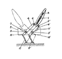
特許文献3の「自動転換装置」では、図15に示すように、座部クッションの傾動による安楽姿勢の形成、及びリンクと支持台との当接による衝撃音発生は解決されているが、流体圧往復機構としてエヤーシリンダー10を用いなければならなから、エヤー供給器やエヤーの供給制御を行うバルブや制御器を備えなければならないから、全体の構造が複雑になっているだけでなく、これらの機器のメンテナンスも余儀なくされるものと考えられる。   In the “automatic conversion device” of Patent Document 3, as shown in FIG. 15, the formation of a comfortable posture by tilting the seat cushion and the generation of impact sound due to the contact between the link and the support base are solved. Since the air cylinder 10 must be used as the pressure reciprocating mechanism, and the air supply device and the valve and controller for air supply control must be provided, not only the overall structure is complicated, but these It is thought that the maintenance of the equipment will also be forced.

すなわち、この特許文献3の「自動転換装置」では、当該文献の第2欄第22行目から第3欄第13行目に記載されているように、「流体圧往復機構としてエヤーシリンダー10を用い、そのピストンロッド11の自由端側に継手部12を介して転換作動リンク13の一旦側を連結するとともに、この転換作動リンク13の他端側を転換作動軸14に連携させる。…この転換作動軸14の先端部にはローラー16が装着されており、…このローラー16が転換用リンク3又は4の内側端縁に沿って自在に回転しながら転換用リンク3又は4を脚台5に対する取付軸17、18部分において回転移動させ、而して背ずり1を前又は後へ転換させ得るようになっている…」ものである。   That is, in the “automatic conversion device” of Patent Document 3, as described in the second column, the 22nd line to the third column, the 13th line of the document, “the air cylinder 10 is used as a fluid pressure reciprocating mechanism”. Used, the one side of the conversion operation link 13 is connected to the free end side of the piston rod 11 via the joint portion 12 and the other end side of the conversion operation link 13 is linked to the conversion operation shaft 14. A roller 16 is attached to the distal end of the operating shaft 14... While the roller 16 rotates freely along the inner edge of the conversion link 3 or 4, the conversion link 3 or 4 is moved with respect to the foot base 5. The mounting shafts 17 and 18 can be rotated and moved so that the back 1 can be turned forward or backward ... ".

ということは、この特許文献3の「自動転換装置」では、「座ぶとん2」を外そうとしても、転換作動軸14の先端部のローラー16が邪魔になり、転換用リンク3又は4を脚台5から外さない限り外せないものとなっている。このことは、汚れた「座ぶとん2」の洗浄等のメンテナンスを行う際には、転換用リンク3又は4を脚台5から外すといった作業が余儀なくされることを意味している。   That is, in the “automatic conversion device” of Patent Document 3, even if it is attempted to remove the “seat belt 2”, the roller 16 at the tip of the conversion operation shaft 14 becomes an obstacle, and the conversion link 3 or 4 is attached to the footrest. Unless it is removed from 5, it can not be removed. This means that work such as removing the conversion link 3 or 4 from the footrest 5 is unavoidable when performing maintenance such as cleaning of the soiled “sitton 2”.

また、一般に、乗物用の座席の座部クッションは、長年の使用により、クッション性能の低下(ヘタリ)が発生する。これによって座り心地が悪くなるために、座部クッションの交換をするために座部クッション枠を簡単に取り外せるようにしておく必要がある。   In general, a seat cushion of a vehicle seat causes deterioration (sagging) of cushion performance due to long-term use. This makes the seating comfort worse, so that it is necessary to be able to easily remove the seat cushion frame in order to replace the seat cushion.

そこで、本発明者等は、座部クッション枠を簡単に取り外せて、転換操作時に衝撃音の発生を極力抑制することのできる転換座席とするにはどうしたらよいか、について種々検討を重ねてきた結果、本発明を完成したのである。   Accordingly, the present inventors have made various studies on how to make a convertible seat that can easily remove the seat cushion frame and suppress the generation of impact sound during the conversion operation as much as possible. As a result, the present invention has been completed.

すなわち、本発明の目的とするところは、まず、座部クッション枠を傾動するものとして使用者が安楽姿勢を取ることができるようにし、かつ転換操作時における衝撃音の発生を極力抑制することのできる転換座席を提供することにある。   That is, the object of the present invention is to first enable the user to take a comfortable posture as tilting the seat cushion frame and to suppress the generation of impact sound during the switching operation as much as possible. It is to provide a convertible seat that can.

また、本発明の他に目的とするところは、座部クッション枠の重量を部分によって異ならせるといった簡単な構造で、転換操作時に衝撃音の発生を極力抑制することのできる転換座席を提供することにある。   Another object of the present invention is to provide a conversion seat that can suppress the generation of impact sound as much as possible with a simple structure in which the weight of the seat cushion frame varies depending on the part. It is in.

さらに、本発明の他に目的とするところは、座部クッション枠を簡単に外せるようにして、座部クッションの洗浄や変換等のメンテナンスが簡単に行えるようにすることのできる転換座席を提供することにある。   Furthermore, another object of the present invention is to provide a convertible seat in which the seat cushion frame can be easily removed, and maintenance such as cleaning and conversion of the seat cushion can be easily performed. There is.

以上の課題を解決するために、まず、請求項1に係る発明の採った手段は、後述する最良形態の説明中で使用する符号を付して説明すると、
「乗物の車室内に固定される左右の基台10上にそれぞれ取り付けられる左右の支持台20と、これらの支持台20間に橋架状態で傾動可能に組み付けられる1つの座部クッション枠30と、各支持台20に揺動可能に組み付けた背当てリンク40とを備えた乗物用転換座席100であって、
座部クッション枠30の側面であって、当該座部クッション枠30の中心線70からずらせた部分に、少なくとも1つのカム50またはピン60を設けるとともに、この少なくとも1つのカム50またはピン60が係合するピン60またはカム50を、背当てリンク40側に設けて、
この背当てリンク40を一方側から他方側に揺動させる間に、ピン60がカム50のカム溝51に係合していき、座部クッション枠30を一方側から他方側に傾斜させるようにしたことを特徴とする乗物用転換座席100」
である。
In order to solve the above problems, first, the means taken by the invention according to claim 1 will be described with reference numerals used in the description of the best mode described below.
“The left and right support bases 20 respectively mounted on the left and right bases 10 fixed in the vehicle interior of the vehicle, and one seat cushion frame 30 assembled between these support bases 20 so as to be tiltable in a bridge state, A vehicle conversion seat 100 including a backrest link 40 that is swingably assembled to each support base 20,
At least one cam 50 or pin 60 is provided on a side surface of the seat cushion frame 30 that is shifted from the center line 70 of the seat cushion frame 30, and the at least one cam 50 or pin 60 is engaged with the seat cushion frame 30. The pin 60 or the cam 50 to be fitted is provided on the back link 40 side,
While the backrest link 40 is swung from one side to the other side, the pin 60 is engaged with the cam groove 51 of the cam 50 so that the seat cushion frame 30 is inclined from one side to the other side. Vehicle conversion seat 100 characterized by
It is.

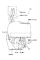
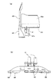
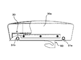
すなわち、本発明に係る乗物用転換座席100は、図1及び図2にも示すように、乗物の車室内に固定される左右の基台10上にそれぞれ取り付けられる左右の支持台20と、これらの支持台20間に橋架状態で傾動可能に組み付けられる1つの座部クッション枠30と、各支持台20に揺動可能に組み付けた背当てリンク40とを備えたものである。なお、各図において背当て40aは明示していないが、この背当て40aは、図2に示すように、各背当てリンク40の上端に取り付けられるものである。   That is, as shown in FIGS. 1 and 2, the vehicle conversion seat 100 according to the present invention includes left and right support bases 20 that are respectively mounted on the left and right bases 10 fixed in the vehicle cabin. These are provided with one seat cushion frame 30 that is assembled between the support bases 20 so as to be tiltable in a bridge state, and a backrest link 40 that is swingably assembled to each support base 20. In addition, although the back support 40a is not clearly shown in each figure, this back support 40a is attached to the upper end of each back support link 40, as shown in FIG.

また、本発明に係る乗物用転換座席100では、図1〜図3に示すように、座部クッション枠30の側面であって、当該座部クッション枠30の中心線70からずらせた部分に、少なくとも1つのカム50またはピン60を設けるとともに、この少なくとも1つのカム50またはピン60が係合するピン60またはカム50を、背当てリンク40側に設けたものである。   Further, in the vehicle conversion seat 100 according to the present invention, as shown in FIGS. 1 to 3, on the side surface of the seat cushion frame 30, which is shifted from the center line 70 of the seat cushion frame 30, At least one cam 50 or pin 60 is provided, and the pin 60 or cam 50 with which the at least one cam 50 or pin 60 engages is provided on the back support link 40 side.

カム50は、座部クッション枠30の側面であって、当該座部クッション枠30の中心線70からずらせた部分に設ける必要がある。何故なら、このカム50に後述する背当てリンク40側のピン60を係合させて、背当てリンク40の揺動に応じて座部クッション枠30を反対側に傾動させるようにし、座部クッション枠30、つまり座部クッション30aを背当てリンク40の揺動側に傾動させて、この座部クッション30a上の使用者が安楽姿勢が取れるようにしなければならないからである。   The cam 50 needs to be provided on the side surface of the seat cushion frame 30 and at a portion shifted from the center line 70 of the seat cushion frame 30. This is because a pin 60 on the back support link 40 described later is engaged with the cam 50 so that the seat cushion frame 30 is tilted to the opposite side in accordance with the swing of the back support link 40. This is because the frame 30, that is, the seat cushion 30a must be tilted toward the swinging side of the backrest link 40 so that the user on the seat cushion 30a can take a comfortable posture.

そして、このカム50に係合するピン60を、背当てリンク40側に設ける必要があるのである。何故なら、これらのピン60及びカム50によって、転換操作のための力が加えられる背当てリンク40と、この背当てリンク40の動きに追随しなければならない座部クッション枠30とを連動させる必要があるからである。ここで、「背当てリンク40側に設ける」とは、背当てリンク40に直接設ける他、後述する最良形態におけるように、この背当てリンク40と同期して揺動する転換軸41に設ける場合等をいう。   And it is necessary to provide the pin 60 engaged with this cam 50 in the backrest link 40 side. This is because the back support link 40 to which a force for a switching operation is applied by these pins 60 and the cam 50 and the seat cushion frame 30 that must follow the movement of the back support link 40 must be interlocked. Because there is. Here, “provided on the back support link 40 side” refers to a case where it is provided directly on the back support link 40 or provided on the conversion shaft 41 that swings in synchronization with the back support link 40 as in the best mode described later. Etc.

以上のことから、各カム50、及びこれに係合するピン60は、それぞれ1つ宛あれば十分であるが、必要に応じて各部分に設けて実施してもよいものであり、座部クッション枠30が図5の(a)に示すような四角形状のものであることを考慮すれば、左右両側面の前後に最大でそれぞれ4個のカム50、及びこれに係合するピン60を設けることができる。   From the above, it is sufficient that each cam 50 and the pin 60 engaged therewith are each addressed to one, but may be provided by being provided in each part as required. Considering that the cushion frame 30 has a quadrangular shape as shown in FIG. 5A, a maximum of four cams 50 and pins 60 that engage with the cams 50 are provided on the front and rear sides of the left and right sides. Can be provided.

後述する最良形態では、図5及び図6の各(b)に示すように、図示右側部分に1個のカム50を設けておき、このカム50に係合するピン60を、図3及び図4に示すように、各背当てリンク40と同期して揺動する転換軸41に各1個設けてある。このようにすれば、座部クッション枠30の支持台20に対する組み付けを、座部クッション枠30の方向性を気にすることなく行えるから有利である。   In the best mode to be described later, as shown in FIGS. 5 and 6B, a single cam 50 is provided on the right side of the figure, and the pin 60 that engages with the cam 50 is shown in FIGS. As shown in FIG. 4, one each is provided on a conversion shaft 41 that swings in synchronization with each backrest link 40. This is advantageous because the seat cushion frame 30 can be assembled to the support base 20 without worrying about the directionality of the seat cushion frame 30.

勿論、背当てリンク40側にカム50を設けておき、このカム50に係合するピン60を座部クッション枠30側に設けて実施しても良いことは言うまでもない。   Needless to say, the cam 50 may be provided on the back support link 40 side, and the pin 60 that engages with the cam 50 may be provided on the seat cushion frame 30 side.

さて、以上のように構成した乗物用転換座席100においては、図11及び図12に示した最良形態におけるような作用を発揮する。これらの最良形態では、背当てリンク40側、つまりこの背当てリンク40と同期して揺動する転換軸41にピン60を設けておき、このピン60に係合するカム50を座部クッション枠30側に設けるようにしてある。   Now, the vehicle conversion seat 100 configured as described above exhibits the operation as in the best mode shown in FIGS. 11 and 12. In these best modes, a pin 60 is provided on the back support link 40 side, that is, a conversion shaft 41 that swings in synchronization with the back support link 40, and the cam 50 that engages with the pin 60 is attached to the seat cushion frame. It is arranged on the 30 side.

図11の(a)〜(c)は、図12の(b)の状態にあった各背当てリンク40及び座部クッション枠30が、図12の(a)の状態へと変化する途中の様子が、(a)〜(c)の順で示してある。すなわち、図12の(b)の状態にあった各背当てリンク40に力を入れて、この背当てリンク40を使用者が起こしたときには、図11の(a)に示した状態になる。なお、このときには、後述する最良形態では、図11の(a)に示してある座部クッション枠30の左側部分を他方よりも重く形成してあるため、座部クッション枠30の左側部分が図示左側に傾動して、ここに取り付けてある着脱ピン31bが支持台20のストッパ22に当接して停止したままとなっている。   (A) to (c) of FIG. 11 are in the middle of changing the backrest links 40 and the seat cushion frame 30 that were in the state of (b) of FIG. 12 to the state of (a) of FIG. The situation is shown in the order of (a) to (c). That is, when a force is applied to each backrest link 40 in the state of FIG. 12B and the user raises the backrest link 40, the state shown in FIG. 11A is obtained. At this time, in the best mode described later, the left side portion of the seat cushion frame 30 shown in FIG. 11A is formed to be heavier than the other, so the left side portion of the seat cushion frame 30 is illustrated. It tilts to the left, and the detachable pin 31b attached here abuts against the stopper 22 of the support base 20 and remains stopped.

この図11の(a)に示した状態になったときには、背当てリンク40側のピン60がカム50のカム溝51内に入り込もうとしているのであるが、カム溝51の開口端は、図6の(b)にも示すように、カム溝51の他の部分に比して大きく開口しているから、各部分の組み付け状態等に少しズレがあったとしても、背当てリンク40側のピン60はカム50のカム溝51内に確実に入り込む。   When the state shown in FIG. 11A is reached, the pin 60 on the backrest link 40 side is about to enter the cam groove 51 of the cam 50. The open end of the cam groove 51 is not shown in FIG. 6 (b), since the opening is larger than the other portions of the cam groove 51, even if there is a slight shift in the assembled state of each portion, the back link 40 side The pin 60 surely enters the cam groove 51 of the cam 50.

次に、背当てリンク40がさらに揺動されて、図11の(b)に示した状態になると、この背当てリンク40に一体化してあるピン60は、カム50のカム溝51の中程まで侵入する。このとき、ピン60はカム50を下方に押し下げ始めることになり、座部クッション枠30を図示時計方向に傾動させ始めることになる。また、カム溝51の幅は既に狭くなってきているし、ピン60がカム50のカム溝51を図示下方に押し下げながら侵入することにより、座部クッション枠30が支持台20に対してガタ付くことはない。   Next, when the back support link 40 is further swung to the state shown in FIG. 11B, the pin 60 integrated with the back support link 40 is located in the middle of the cam groove 51 of the cam 50. Invade until. At this time, the pin 60 starts to push down the cam 50 and starts to tilt the seat cushion frame 30 in the clockwise direction in the drawing. Further, the width of the cam groove 51 has already become narrower, and the seat cushion frame 30 is rattled with respect to the support base 20 by the pin 60 entering while pushing down the cam groove 51 of the cam 50 downward in the figure. There is nothing.

背当てリンク40がさらに揺動されて、図11の(c)に示した状態になると、固定ピン31aがストッパ22上に当接し、座部クッション枠30の傾動は完了する。このとき、背当てリンク40側のピン60は、カム50のカム溝51内に係合したままであるから、座部クッション枠30が不用意にガタ付くことはない。なお、背当てリンク40は、座部クッション枠30側に設けてある固定ピン31a及びストッパ22上に未だ当接していない。   When the back support link 40 is further swung to the state shown in FIG. 11C, the fixing pin 31a comes into contact with the stopper 22 and the tilting of the seat cushion frame 30 is completed. At this time, since the pin 60 on the back support link 40 remains engaged in the cam groove 51 of the cam 50, the seat cushion frame 30 is not inadvertently rattled. The back support link 40 is not yet in contact with the fixing pin 31a and the stopper 22 provided on the seat cushion frame 30 side.

最後に、図12の(a)に示す状態になるのであるが、このときには、座部クッション枠30の傾動は完了しており、揺動してきた背当てリンク40は、支持台20側のストッパ22上に当接するとともに、その押え溝43によって座部クッション枠30側の固定ピン31a(既にストッパ22上に当接している)を上方から押さえ込むことになる。   Finally, the state shown in FIG. 12A is reached. At this time, the tilting of the seat cushion frame 30 is completed, and the backrest link 40 that has been swung is a stopper on the support base 20 side. 22 and the pressing groove 43 presses the fixing pin 31a on the seat cushion frame 30 side (which is already in contact with the stopper 22) from above.

つまり、背当てリンク40が、既にストッパ22に当接している、つまり振動しにくい状態になっている固定ピン31aを押さえ込むのであるから、浮いた状態にあるものに当接するのとは異なって、衝撃音の発生を極力抑制することができる。勿論、ストッパ22は弾性材料からなっているから、図11の(c)で示した固定ピン31aとの当接時も、図12の(a)で示した背当てリンク40との当接時も、いずれの場合も衝撃音の発生を極力抑制することができる。   That is, since the back support link 40 is already in contact with the stopper 22, that is, presses the fixing pin 31 a that is in a state of being difficult to vibrate, unlike the contact with the floating pin, Generation of impact sound can be suppressed as much as possible. Of course, since the stopper 22 is made of an elastic material, the stopper 22 is in contact with the fixing pin 31a shown in FIG. 11C and also in contact with the back link 40 shown in FIG. In either case, the generation of impact sound can be suppressed as much as possible.

以上の結果、本発明に係る乗物用転換座席100では、その転換操作時において、背当てリンク40の揺動に基づく衝撃音の発生を極力抑制することができることは勿論、座部クッション枠30の傾動によっても衝撃音の発生を極力抑制することができるのである。   As a result of the above, in the vehicle conversion seat 100 according to the present invention, it is possible to suppress the generation of an impact sound due to the swinging of the backrest link 40 as much as possible during the conversion operation. The generation of impact sound can be suppressed as much as possible even by tilting.

また、上記課題を解決するために、請求項2に係る発明の採った手段は、上記請求項1に記載の乗物用転換座席100について、
「座部クッション枠30の、中心線70の一方側部分を他方側部分よりも重く構成するとともに、前記他方側部分にカム50を取り付けるようにしたこと」
である。
Moreover, in order to solve the said subject, the means which the invention which concerns on Claim 2 took about the convertible seat 100 for vehicles of the said Claim 1,
“The one side portion of the center line 70 of the seat cushion frame 30 is configured to be heavier than the other side portion, and the cam 50 is attached to the other side portion.”
It is.

すなわち、この請求項2に係る乗物用転換座席100では、その座部クッション枠30の重量が中心線70の両側で異なっているものであり、その軽い側の部分に前述したカム50が設けてある。なお、このカム50を設けた後も、これを取り付けた部分は、反対側より軽いものである。   That is, in the vehicle conversion seat 100 according to the second aspect, the weight of the seat cushion frame 30 is different on both sides of the center line 70, and the cam 50 described above is provided on the light side portion. is there. Even after the cam 50 is provided, the portion to which the cam 50 is attached is lighter than the opposite side.

以上のように構成するとどうなるかは、図11の(a)〜(c)、及び図12の(a)〜(b)に示してある。例えば、図12の(a)に示した状態から図12の(b)に示した状態へと座席転換を行うために、各背当てリンク40を引き起こした場合、まず、図11の(a)に示したようになる。   What happens when configured as described above is shown in FIGS. 11A to 11C and FIGS. 12A to 12B. For example, when each backrest link 40 is caused to change seats from the state shown in FIG. 12A to the state shown in FIG. 12B, first, FIG. As shown in

つまり、図11の(c)、同(b)を経て、図11の(a)に示したように、各背当てリンク40を引き起こすと、それまでの各部における係合や押圧は解除されるから、座部クッション枠30の重い側の部分(図11では図示左方部分)が自重によって下がり、その側面に取り付けてあった着脱ピン31bが、支持台20側の弾性材料からなるストッパ22に当接する。   That is, as shown in (a) of FIG. 11 through (c) and (b) of FIG. 11, when each back support link 40 is caused, the engagement and press in each part until then are released. Thus, the heavy side portion (the left portion in the figure in FIG. 11) of the seat cushion frame 30 is lowered by its own weight, and the detachable pin 31b attached to the side surface is attached to the stopper 22 made of an elastic material on the support base 20 side. Abut.

さらに、背当てリンク40を倒して行けば、背当てリンク40側の押さえ溝43が着脱ピン31b上に係合して当該着脱ピン31bをストッパ22上に押さえ付けるのであるが、このときまでには、上述したように着脱ピン31bがストッパ22上に既に当接しているのであるから、衝撃音の発生を極力抑制することができる。そして、座部クッション枠30は、最終的に図12の(b)の状態となるのである。   Furthermore, if the back support link 40 is tilted down, the pressing groove 43 on the back support link 40 side engages with the attaching / detaching pin 31b and presses the attaching / detaching pin 31b onto the stopper 22. Since the detachable pin 31b is already in contact with the stopper 22 as described above, the generation of impact sound can be suppressed as much as possible. Then, the seat cushion frame 30 is finally in the state shown in FIG.

換言すれば、この請求項2の乗物用転換座席100は、その座部クッション枠30の一部を重くすることにより、この座部クッション枠30における係合や押圧が解除されたときに、その重い側の部分が自重により傾動して、この部分に設けてある着脱ピン31bが支持台20側のストッパ22に当接するから、浮いたままの状態の着脱ピン31bに背当てリンク40が当接するようなことはなく、衝撃音の発生を極力抑制することができるのである。   In other words, the vehicle conversion seat 100 according to the second aspect of the present invention is configured such that when the engagement or the press in the seat cushion frame 30 is released by making a part of the seat cushion frame 30 heavy, The heavy side portion is tilted by its own weight, and the detachable pin 31b provided in this portion abuts against the stopper 22 on the support base 20, so that the back support link 40 abuts on the detachable pin 31b in a floating state. There is no such thing, and the generation of impact sound can be suppressed as much as possible.

従って、この請求項2の乗物用転換座席100は、上記請求項1のそれと同様な機能を発揮する他、座部クッション30枠の一方側を重くするという簡単な構造で、転換操作時に衝撃音の発生を極力抑制することができるのである。   Accordingly, the vehicle conversion seat 100 according to the second aspect has a simple structure in which one side of the frame of the seat cushion 30 is made heavy in addition to performing the same function as that of the first aspect, and an impact sound is generated during the conversion operation. It is possible to suppress the generation of as much as possible.

さらに、上記課題を解決するために、請求項3に係る発明の採った手段は、上記請求項1または請求項2に記載の乗物用転換座席100について、
「座部クッション枠30の側面の、中心線70の両側に位置する部分に、背当てリンク40の押さえ溝43によって支持台20側に押圧される固定ピン31a及び着脱ピン31bを取り付けて、着脱ピン31bのみを取り外すことにより、座部クッション枠30及び座部クッション30aを支持台20から取り外せるようにしたこと」
である。
Furthermore, in order to solve the above-mentioned problem, the means taken by the invention according to claim 3 is about the vehicle conversion seat 100 according to claim 1 or claim 2,
“Attaching and removing the fixing pin 31a and the detachable pin 31b that are pressed against the support base 20 side by the pressing groove 43 of the back support link 40 on the sides of the seat cushion frame 30 located on both sides of the center line 70. By removing only the pin 31b, the seat cushion frame 30 and the seat cushion 30a can be detached from the support base 20. "
It is.

すなわち、この請求項3に係る乗物用転換座席100では、図5及び図6に示すように、座部クッション枠30の側面に固定ピン31a及び着脱ピン31bを取り付けたものであり、具体的には、図5の(a)に示すように、座部クッション枠30の側面の、中心線70の図示右側に位置する部分に固定ピン31aを、また中心線70の図示左側に位置する部分に着脱ピン31bを設けたものである。これらの固定ピン31a及び着脱ピン31bは、図12の(a)及び(b)に示すように、背当てリンク40の押さえ溝43によって支持台20側に押圧されるものである。   That is, in the vehicle conversion seat 100 according to the third aspect, as shown in FIGS. 5 and 6, the fixing pin 31 a and the detachable pin 31 b are attached to the side surface of the seat cushion frame 30. As shown in FIG. 5 (a), a fixing pin 31a is provided on the side surface of the seat cushion frame 30 on the right side of the center line 70 in the figure, and on the left side of the center line 70 in the figure. A detachable pin 31b is provided. The fixing pin 31a and the detachable pin 31b are pressed toward the support base 20 by the pressing groove 43 of the back link 40 as shown in FIGS. 12 (a) and 12 (b).

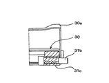
固定ピン31aは、文字通り座部クッション枠30の側面に固定的に設けられるものであるが、着脱ピン31bは、図5の(a)及び(b)に示すように、固定ピン31aとは反対側にピン取付部31cを設けておいて、このピン取付部31cに対して着脱できるようにしたものである。つまり、固定ピン31aは外せないが、着脱ピン31bは、例えばピン取付部31cに螺着され、ドライバー等の工具を使用すればこのピン取付部31cから簡単に取り外せるものなのである。   The fixing pin 31a is literally provided on the side surface of the seat cushion frame 30, but the detachable pin 31b is opposite to the fixing pin 31a as shown in FIGS. 5 (a) and 5 (b). A pin mounting portion 31c is provided on the side so that it can be attached to and detached from the pin mounting portion 31c. That is, the fixing pin 31a cannot be removed, but the detachable pin 31b is screwed into, for example, the pin attachment portion 31c and can be easily removed from the pin attachment portion 31c by using a tool such as a screwdriver.

ところで、座部クッション枠30の両側であって中心線70上には、図5及び図6に示すように、係合部33が形成してあり、この係合部33は、図4に示した支持台20側の支持突起21上に係合される。つまり、この座部クッション枠30は支持台20の支持突起21上に傾動自在に載置されているだけであり、上記固定ピン31a及び着脱ピン31b以外では支持台20側に係合する部分がないのである。   Incidentally, on both sides of the seat cushion frame 30 and on the center line 70, as shown in FIGS. 5 and 6, engaging portions 33 are formed, and these engaging portions 33 are shown in FIG. It is engaged on the support protrusion 21 on the support base 20 side. In other words, the seat cushion frame 30 is merely placed on the support protrusion 21 of the support base 20 so as to be tiltable, and there is a portion engaged with the support base 20 other than the fixing pin 31a and the detachable pin 31b. There is no.

この乗物用転換座席100においては、その座部クッション枠30上の座部クッション30aが汚れたため、これを洗浄したい場合がある。この洗浄作業は、座部クッション30aを支持台20に組み込んだまま行うことも可能ではあるが、この請求項3の乗物用転換座席100では、この座部クッション枠30を座部クッション30aとともに支持台20から外すことができるから、そのメンテナンスが容易に行えるのである。このことは、座部クッション30aを交換するときにも同様である。   In the vehicle conversion seat 100, the seat cushion 30a on the seat cushion frame 30 is contaminated, so that it may be desired to clean it. This cleaning operation can be performed while the seat cushion 30a is incorporated in the support base 20. However, in the vehicle conversion seat 100 according to claim 3, the seat cushion frame 30 is supported together with the seat cushion 30a. Since it can be removed from the base 20, its maintenance can be easily performed. The same applies to the replacement of the seat cushion 30a.

この座部クッション枠30を外すには、次のようにする。すなわち、図12の(a)に示すように、まず各背当てリンク40を固定ピン31a側に当接させておいて着脱ピン31bの周囲に邪魔者がない状態にしておき、この状態で着脱ピン31bをピン取付部31cから外すのである。次に、図12の(b)に示すように、各背当てリンク40を反対側に倒して、それまで押さえていた固定ピン31aを自由にすれば、背当てリンク40と座部クッション枠30とを関連付けていたものが無くなるから、座部クッション枠30を座部クッション30aとともに、図示右上方向に引き抜けば、当該座部クッション枠30の取り外しは完了する。   The seat cushion frame 30 is removed as follows. That is, as shown in FIG. 12A, first, each back support link 40 is brought into contact with the fixing pin 31a so that there is no obstacle around the attaching / detaching pin 31b. The pin 31b is removed from the pin attachment portion 31c. Next, as shown in FIG. 12 (b), if each back link 40 is tilted to the opposite side and the fixing pin 31 a that has been pressed is released, the back link 40 and the seat cushion frame 30. Therefore, if the seat cushion frame 30 is pulled out together with the seat cushion 30a in the upper right direction in the figure, the removal of the seat cushion frame 30 is completed.

従って、この請求項3の乗物用転換座席100は、上記請求項1または請求項2のそれと同様な機能を発揮する他、座部クッション枠30を簡単に外せることができて、座部クッション30aの洗浄や交換等のメンテナンスが簡単に行えるのである。   Therefore, the vehicle conversion seat 100 according to the third aspect of the present invention can perform the same function as that of the first or second aspect of the present invention, and can easily remove the seat cushion frame 30 so that the seat cushion 30a can be removed. Maintenance such as cleaning and replacement can be easily performed.

以上、説明した通り、本発明においては、
「乗物の車室内に固定される左右の基台10上にそれぞれ取り付けられる左右の支持台20と、これらの支持台20間に橋架状態で傾動可能に組み付けられる1つの座部クッション枠30と、各支持台20に揺動可能に組み付けた背当てリンク40とを備えた乗物用転換座席100であって、
座部クッション枠30の側面であって、当該座部クッション枠30の中心線70からずらせた部分に、少なくとも1つのカム50またはピン60を設けるとともに、この少なくとも1つのカム50またはピン60が係合するピン60またはカム50を、背当てリンク40側に設けて、
この背当てリンク40を一方側から他方側に揺動させる間に、ピン60がカム50のカム溝51に係合していき、座部クッション枠30を一方側から他方側に傾斜させるようにしたこと」
にその構成上の特徴があり、これにより、座部クッション枠30を傾動するものとして使用者が安楽姿勢を取ることができるようにし、かつ転換操作時に衝撃音の発生を極力抑制することができる転換座席100を提供することができるのである。
As described above, in the present invention,
“The left and right support bases 20 respectively mounted on the left and right bases 10 fixed in the vehicle interior of the vehicle, and one seat cushion frame 30 assembled between these support bases 20 so as to be tiltable in a bridge state, A vehicle conversion seat 100 comprising a backrest link 40 slidably assembled to each support base 20,
At least one cam 50 or pin 60 is provided on a side surface of the seat cushion frame 30 that is shifted from the center line 70 of the seat cushion frame 30, and the at least one cam 50 or pin 60 is engaged. The pin 60 or the cam 50 to be fitted is provided on the back support link 40 side,
While the backrest link 40 is swung from one side to the other side, the pin 60 is engaged with the cam groove 51 of the cam 50 so that the seat cushion frame 30 is inclined from one side to the other side. What I did "
There is a characteristic in the structure, and this allows the user to take a comfortable posture as tilting the seat cushion frame 30, and can suppress the generation of impact sound during the switching operation as much as possible. A convertible seat 100 can be provided.

また、請求項2に係る乗物用転換座席100においては、
「座部クッション枠30の、中心線70の一方側部分を他方側部分よりも重く構成するとともに、前記他方側部分にカム50を取り付けるようにしたこと」
にその構成上の特徴があり、これにより、上記請求項1の乗物用転換座席100と同様な効果を発揮する他、簡単な構造で転換操作時に衝撃音の発生を極力抑制することができるのである。
In the vehicle conversion seat 100 according to claim 2,
“The one side portion of the center line 70 of the seat cushion frame 30 is configured to be heavier than the other side portion, and the cam 50 is attached to the other side portion.”
In addition to exhibiting the same effects as those of the vehicle conversion seat 100 of the first aspect, it is possible to suppress the generation of impact sound at the time of conversion operation with a simple structure as much as possible. is there.

さらに、請求項3に係る乗物用転換座席100では、
「座部クッション枠30の側面の、中心線70の両側に位置する部分に、背当てリンク40の押さえ溝43によって支持台20側に押圧される固定ピン31a及び着脱ピン31bを取り付けて、着脱ピン31bのみを取り外すことにより、座部クッション枠30及び座部クッション30aを支持台20から取り外せるようにしたこと」
のその構成上の特徴があり、これにより、上記請求項1または2の乗物用転換座席100と同様な効果を発揮する他、座部クッション枠30を簡単に外すことができ、座部クッション30aの洗浄や交換等のメンテナンスが簡単に行えるものとなっているのである。
Further, in the vehicle conversion seat 100 according to claim 3,
“Attaching and removing the fixing pin 31a and the detachable pin 31b that are pressed against the support base 20 side by the pressing groove 43 of the back support link 40 on the sides of the seat cushion frame 30 located on both sides of the center line 70. By removing only the pin 31b, the seat cushion frame 30 and the seat cushion 30a can be detached from the support base 20. "
Therefore, the seat cushion frame 30 can be easily removed, and the seat cushion 30a can be easily removed. This makes it easy to perform maintenance such as cleaning and replacement.

次に、上記のように構成した各請求項に係る発明を、図面に示した最良の形態である乗物用転換座席100について説明するが、この最良形態の乗物用転換座席100は、上記各請求項の発明全てを含むものである。   Next, the invention according to each claim configured as described above will be described with respect to the vehicle conversion seat 100 which is the best mode shown in the drawings. All the inventions of the item are included.

図1及び図2には、本最良形態に係る乗物用転換座席100が示してあるが、この乗物用転換座席100は、乗物の車室内に固定される左右の基台10上にそれぞれ取り付けられる左右の支持台20と、これらの支持台20間に橋架状態で傾動可能に組み付けられる1つの座部クッション枠30と、各支持台20に揺動可能に組み付けた背当てリンク40とを備えたものである。   FIGS. 1 and 2 show a vehicle conversion seat 100 according to the best mode. The vehicle conversion seat 100 is mounted on left and right bases 10 fixed in a vehicle cabin. The left and right support bases 20, one seat cushion frame 30 that can be tiltably assembled between the support bases 20 in a bridge state, and a backrest link 40 that is swingably assembled to each support base 20. Is.

基台10としては、これが設置させるべき乗物の床面上の状態に応じて、図1の図示左方に示したような形態のものが採用されることもあるが、少なくとも、図1の図示右側に示した基台10が採用される。この右側の基台10内には、図1及び図4に示すように、後述する背当てリンク40の傾動操作を補助するためのスプリング11が収納されるものである。このスプリング11が引張スプリングである場合、背当てリンク40の揺動操作時には、スプリング11の引張力により背当てリンク40の揺動操作が補助されるとともに、背当てリンク40が次に説明するストッパ22に当接する際の衝撃をも緩和する。   As the base 10, there may be adopted a form as shown on the left side of FIG. 1 depending on the state of the vehicle to be installed, but at least the illustration of FIG. The base 10 shown on the right side is employed. As shown in FIGS. 1 and 4, a spring 11 for assisting a tilting operation of a backrest link 40 described later is accommodated in the right base 10. When the spring 11 is a tension spring, the swinging operation of the backrest link 40 is assisted by the tensile force of the spring 11 during the swinging operation of the backrest link 40, and the backrest link 40 is a stopper described below. The impact at the time of abutting 22 is also reduced.

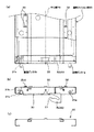
支持台20は、図4の(a)及び(b)に示したように、側面形状が「ゴンドラ型」になっており、左右にアーム部が立ち上がっていて、このアーム部の上面に、弾性材料からなるストッパ22が取り付けてあり、このストッパ22によって、背当てリンク40、固定ピン31a、及び着脱ピン31bを弾発的に受け止るようになっている。勿論、これらの支持台20は、図1にも示したように、一つの背当て40aに対して左右2つが使用されるものであり、これら2つの支持台20は、後述する背当てリンク40と一体的に揺動する転換軸41によって連結されるものである。   As shown in FIGS. 4A and 4B, the support base 20 has a “gondola-type” side surface shape, and has arm portions standing up and down. A stopper 22 made of a material is attached, and by this stopper 22, the backrest link 40, the fixing pin 31a, and the detachable pin 31b are received elastically. Of course, as shown in FIG. 1, two left and right support bases 20 are used for one back support 40a, and these two support bases 20 are back support links 40 described later. Are connected by a conversion shaft 41 that oscillates integrally.

また、この支持台20の中心には支持突起21が突出形成してあり、この支持突起21上には、後述する座部クッション枠30の両側に形成してある係合部33が係合されることになる。   Further, a support protrusion 21 protrudes from the center of the support base 20, and engaging portions 33 formed on both sides of a seat cushion frame 30 described later are engaged on the support protrusion 21. Will be.

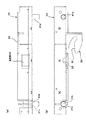
座部クッション枠30は、図5〜図9に示したように、平枠形状に形成したものであり、その上に人が座ることになる柔らかい座部クッション30aが取り付けられるものである。この座部クッション枠30の上面には、図5の(a)及び(b)に示したように、爪32が形成してあり、この爪32を利用することにより、座部クッション枠30上に対する座部クッション30aの一体化が簡単にできるようにしてある。   As shown in FIGS. 5 to 9, the seat cushion frame 30 is formed in a flat frame shape, and a soft seat cushion 30 a on which a person will sit is attached. As shown in FIGS. 5A and 5B, a claw 32 is formed on the upper surface of the seat cushion frame 30. By using this claw 32, The seat cushion 30a can be easily integrated.

また、この座部クッション枠30については、図5の(a)に示したように、その左右側部上面であって中心線70と交差する部分に、前述した支持台20側の支持突起21が係合することになる係合部33が、それぞれ形成してある。   As for the seat cushion frame 30, as shown in FIG. 5A, the support protrusions 21 on the support base 20 described above are formed on the upper surfaces of the left and right side portions and intersecting the center line 70. Engaging portions 33 to be engaged with each other are formed.

そして、この座部クッション枠30の左右両側面には、図5及び図6に示したように、固定ピン31a及び着脱ピン31bが設けてあり、これらの固定ピン31a及び着脱ピン31bは、座部クッション枠30の中心線70に対して同じ距離で前後に配置してある。固定ピン31aは、座部クッション枠30の側面に、溶接等の手段によって一体化したものであるが、着脱ピン31bは、図5及び図6の各(a)や図10に示したように、座部クッション枠30の側面にピン取付部31cを取り付けておいて、このピン取付部31cに文字通り着脱されるものである。   And as shown in FIG.5 and FIG.6, the fixing pin 31a and the detachable pin 31b are provided in the right-and-left both sides | surfaces of this seat part cushion frame 30, These fixed pin 31a and the detachable pin 31b are seats. It arrange | positions back and forth by the same distance with respect to the centerline 70 of the part cushion frame 30. FIG. The fixing pin 31a is integrated with the side surface of the seat cushion frame 30 by means of welding or the like, but the detachable pin 31b is as shown in each of FIGS. 5 (a) and 6 (a) and FIG. The pin attachment portion 31c is attached to the side surface of the seat cushion frame 30 and is literally attached to and detached from the pin attachment portion 31c.

勿論、これらの固定ピン31a及び着脱ピン31bは、図8の(a)にも示したように、それぞれ座部クッション枠30の同じ側に取り付けられるものであり、例えば、着脱ピン31bを外して図12の(b)に示したよう状態としたときに、座部クッション枠30及びこれと一体的な座部クッション30aを、図12の(b)の図示右上方向へ簡単に引き出すことができるものである。   Of course, as shown in FIG. 8A, the fixing pin 31a and the detachable pin 31b are respectively attached to the same side of the seat cushion frame 30. For example, the detachable pin 31b is removed. When the state shown in FIG. 12B is obtained, the seat cushion frame 30 and the seat cushion 30a integrated therewith can be easily pulled out in the upper right direction of FIG. 12B. Is.

背当てリンク40は、所謂「平行リンク」を構成するものであり、その上端には、図2中の仮想線にて示したように、背当て40aが取り付けられるものである。つまり、この平行リンクである背当てリンク40によって支持台20側に連結される背当て40aは、背当てリンク40が揺動された側とは反対に常に傾斜することになるものであり、人がその前面に凭れ掛かったときに、上体について安楽姿勢が採れるようになっている。   The back support link 40 constitutes a so-called “parallel link”, and a back support 40 a is attached to the upper end of the back support link 40 as indicated by the phantom line in FIG. 2. In other words, the back support 40a connected to the support base 20 side by the back support link 40, which is a parallel link, always inclines opposite to the side on which the back support link 40 is swung. When he leans on the front, he can take an easy posture on his upper body.

また、この背当てリンク40は、図1にも示したように、左右の各支持台20に組み付けられるものであり、これによって背当て40aの両側を支持するものである。本最良形態では、図2にも示したように、これらの一対の背当てリンク40に、各支持台20の内側に配置される転換軸41を中心軸41aを介して組み付け、この転換軸41と背当てリンク40とが一体的に揺動するようにしてある。この転換軸41には、図4に示したように、スプリングアーム42が一体的に設けてあり、このスプリングアーム42は上述した基台10内にて揺動するようにしてある。そして、このスプリングアーム42にはスプリング11が連結してあって、このスプリング11の作用によって背当てリンク40の揺動操作が行い易くなるようにしてある。   Further, as shown in FIG. 1, the backrest link 40 is assembled to the left and right support bases 20, and thereby supports both sides of the backrest 40a. In the present best mode, as shown in FIG. 2, the conversion shaft 41 disposed inside each support base 20 is assembled to the pair of backrest links 40 via the central shaft 41 a. And the back support link 40 swing together. As shown in FIG. 4, a spring arm 42 is integrally provided on the conversion shaft 41, and the spring arm 42 swings in the base 10 described above. The spring arm 42 is connected to the spring 11 so that the back link 40 can be easily swung by the action of the spring 11.

さらに、これら各背当てリンク40には、図4の(a)にて示したように、その中央部分の外側面に押え溝43が形成してある。この押え溝43は、図12に示したように、座部クッション枠30側の固定ピン31aまたは着脱ピン31bを支持台20側に確実に押圧するようにするものであり、転換後に傾動完了した座部クッション枠30の位置を固定するものである。   Further, as shown in FIG. 4A, each of the back support links 40 is formed with a pressing groove 43 on the outer surface of the central portion thereof. As shown in FIG. 12, the pressing groove 43 is configured to reliably press the fixing pin 31a or the detachable pin 31b on the seat cushion frame 30 side toward the support base 20, and the tilting is completed after the conversion. The position of the seat cushion frame 30 is fixed.

そして、上述した座部クッション枠30の側面下部には、図2、図6の(b)、図7、図9、図11、及び図12に示したように、カム50が一体的に取り付けてある。このカム50は、本最良形態の場合、前述した固定ピン31aと同じ側に一個だけ取り付けてあり、そのカム溝51は、着脱ピン31b側に向けて開口している。このカム溝51は、図6の(b)にも示したように、入り口部分が大きく、中に入るに従って後述するピン60の直径程度の幅となるようにしてある。   Then, the cam 50 is integrally attached to the lower portion of the side surface of the seat cushion frame 30 described above, as shown in FIGS. 2, 6B, 7, 9, 11, and 12. It is. In the case of this best mode, only one cam 50 is attached on the same side as the fixing pin 31a described above, and the cam groove 51 opens toward the detachable pin 31b. As shown in FIG. 6 (b), the cam groove 51 has a large entrance portion and has a width about the diameter of the pin 60 to be described later as it enters.

上記のカム50のカム溝51にはピン60が係合するのであるが、このピン60は、図2及び図4に示したように、上述した背当てリンク40と一体的に揺動する転換軸41に取り付けてある。本最良形態では、カム50は一個であるが、このピン60については、図4の(a)にて示したように、両方の転換軸41についてそれぞれ取り付けてある。このようにしたのは、座部クッション枠30を図9に示したのとは反対にして各支持台20に組み込んだときにも、カム50に係合するピン60が存在するようにするためである。   The pin 60 is engaged with the cam groove 51 of the cam 50. As shown in FIGS. 2 and 4, the pin 60 is a switch that swings integrally with the backrest link 40 described above. It is attached to the shaft 41. In this best mode, the number of cams 50 is one, but the pin 60 is attached to both of the conversion shafts 41 as shown in FIG. This is done so that the pin 60 that engages with the cam 50 exists even when the seat cushion frame 30 is incorporated in each support base 20 in the opposite manner to that shown in FIG. It is.

(その他の実施例)
上述した最良形態では、カム50を座部クッション枠30の側面に一個だけ取り付けた例を示しているが、このカム50は、中心線70の前後にそれぞれ取り付けて実施してもよいものである。この場合には、各カム50のカム溝51は向き合うようにするとともに、ピン60を各背当てリンク40側に設けておかなければならないが、座部クッション枠30がその中心線70の両側において同じ重量である場合に有効である。何故なら、当該乗物用転換座席100をどちらに転換する場合においても、必ずカム50とピン60との係合によって座部クッション枠30の傾動が行えるからである。
(Other examples)
In the best mode described above, an example in which only one cam 50 is attached to the side surface of the seat cushion frame 30 is shown. However, the cam 50 may be attached to the front and rear of the center line 70, respectively. . In this case, the cam grooves 51 of the cams 50 face each other and the pins 60 must be provided on the back support links 40 side, but the seat cushion frame 30 is located on both sides of the center line 70. It is effective when the weight is the same. This is because the seat cushion frame 30 can always be tilted by the engagement of the cam 50 and the pin 60 when the vehicle conversion seat 100 is converted to either direction.

また、背当てリンク40の押え溝43によって押圧される固定ピン31aは、これを着脱ピン31bに代えて実施してもよい。そうすれば、全てが着脱ピン31bとなってこれを座部クッション枠30側から簡単に外せるから、座部クッション30aが設けてある座部クッション枠30の各支持台20からの取り外しが簡単に行えるからである。   Moreover, you may implement the fixing pin 31a pressed by the pressing groove 43 of the backrest link 40 instead of this attaching / detaching pin 31b. Then, since all become the detachable pins 31b and can be easily removed from the seat cushion frame 30 side, the seat cushion frame 30 provided with the seat cushion 30a can be easily detached from each support base 20. This is because it can be done.

本発明に係る乗物用転換座席を構成する基台と支持台、及び背当てリンクとの関係を示す分解斜視図である。It is a disassembled perspective view which shows the relationship between the base which comprises the conversion seat for vehicles which concerns on this invention, a support stand, and a backrest link. 同乗物用転換座席の支持台に対する、背当てリンク、転換軸、カム及びピンの各位置関係を示す部分拡大斜視図である。It is a partial expansion perspective view which shows each positional relationship of a backrest link, a conversion shaft, a cam, and a pin with respect to the support stand of the vehicle conversion seat. 図2に示したものの見る方向を変えて示すもので、(a)は部分正面図、(b)は座部クッション枠及び座部クッションを取り外した状態の部分平面図である。FIG. 3 is a partial front view of what is shown in FIG. 2, and (b) is a partial plan view of a state in which a seat cushion frame and a seat cushion are removed. 同乗物用転換座席を構成している基台、支持台、スプリング、及び背当てリンクの位置関係を示すもので、(a)は側面図、(b)は正面図である。The positional relationship of the base, the support stand, the spring, and the backrest link which comprise the convertible seat for vehicles is shown, (a) is a side view, (b) is a front view. 同乗物用転換座席を構成している座部クッション枠を示すもので、(a)は部分平面図、(b)は側面図、(c)は断面図である。The seat cushion frame which comprises the conversion seat for vehicles is shown, (a) is a partial top view, (b) is a side view, (c) is sectional drawing. 同座部クッション枠の端部分を拡大して示すもので、(a)は平面図、(b)は側面図である。The edge part of the same seat part cushion frame is expanded and shown, (a) is a top view and (b) is a side view. 同座部クッション枠の端部分を示すもので、(a)は一方側部分の斜視図、(b)は他方側部分の斜視図である。The edge part of the seat part cushion frame is shown, (a) is a perspective view of one side part, (b) is a perspective view of the other side part. 座部クッションを取り付けた座部クッション枠を示すもので、(a)は平面図、(b)は正面図である。The seat part cushion frame which attached the seat part cushion is shown, (a) is a top view, (b) is a front view. 座部クッションを取り付けた座部クッション枠の部分破断側面図である。It is a partial fracture side view of the seat part cushion frame which attached the seat part cushion. 図8の(a)中の1−1線に沿ってみた部分縦断面図である。It is the partial longitudinal cross-sectional view seen along the 1-1 line in (a) of FIG. 背当てリンクを支持台に対して揺動させたときの状態を示すもので、(a)は背当てリンクが直立した状態の側面図、(b)はカムのカム溝にピンが係合したときの状態の側面図、(c)は座部クッション枠の傾動が完了したときの側面図である。The state when the back support link is swung with respect to the support base is shown. (A) is a side view of the back support link in an upright state, and (b) is the pin engaged with the cam groove of the cam. (C) is a side view when the tilting of the seat cushion frame is completed. 背当てリンクを支持台に対して揺動させたときの状態を示すもので、(a)は背当てリンクが右側に完全に揺動された状態の側面図、(b)は背当てリンクが左側に完全に揺動された状態の側面図である。It shows a state when the back support link is swung with respect to the support base, (a) is a side view of the state where the back support link is completely swung to the right side, and (b) is the back support link. It is a side view of the state swung completely to the left. 従来の技術を示す概略側面図である。It is a schematic side view which shows the prior art. 従来の別の技術を示す概略側面図である。It is a schematic side view which shows another conventional technique. 従来のさらに別の技術を示す部分側面図である。It is a partial side view which shows another conventional technique.

符号の説明Explanation of symbols

100 乗物用転換座席
10 基台
11 スプリング
20 支持台
21 支持突起
22 ストッパ
30 座部クッション枠
30a 座部クッション
31a 固定ピン
31b 着脱ピン
31c ピン取付部
32 爪
33 係合部
40 背当てリンク
40a 背当て
41 転換軸
41a 中心軸
42 スプリングアーム
43 押え溝
50 カム
51 カム溝
60 ピン
70 中心線
DESCRIPTION OF SYMBOLS 100 Convertible seat for vehicles 10 Base 11 Spring 20 Support base 21 Support protrusion 22 Stopper 30 Seat cushion frame 30a Seat cushion 31a Fixed pin 31b Detachable pin 31c Pin attachment part 32 Claw 33 Engagement part 40 Back link 40a Back rest 41 Conversion shaft 41a Center shaft 42 Spring arm 43 Pressing groove 50 Cam 51 Cam groove 60 Pin 70 Center line

Claims (3)

乗物の車室内に固定される左右の基台上にそれぞれ取り付けられる左右の支持台と、これらの支持台間に橋架状態で傾動可能に組み付けられる1つの座部クッション枠と、前記各支持台に揺動可能に組み付けた背当てリンクとを備えた乗物用転換座席であって、
前記座部クッション枠の側面であって、当該座部クッション枠の中心線からずらせた部分に、少なくとも1つのカムまたはピンを設けるとともに、この少なくとも1つのカムまたはピンが係合するピンまたはカムを、前記背当てリンク側に設けて、
この背当てリンクを一方側から他方側に揺動させる間に、前記ピンが前記カムのカム溝に係合していき、前記座部クッション枠を一方側から他方側に傾斜させるようにしたことを特徴とする乗物用転換座席。
Left and right support bases respectively mounted on left and right bases fixed in the vehicle interior of the vehicle, one seat cushion frame assembled so as to be able to tilt in a bridge state between these support bases, and each of the support bases A vehicle conversion seat having a backrest link assembled in a swingable manner,
At least one cam or pin is provided on a side surface of the seat cushion frame and is shifted from the center line of the seat cushion frame, and a pin or cam to which the at least one cam or pin is engaged is provided. , Provided on the back support link side,
While the backrest link is swung from one side to the other side, the pin is engaged with the cam groove of the cam, and the seat cushion frame is inclined from one side to the other side. Convertible seat for vehicles.
前記座部クッション枠の、前記中心線の一方側部分を他方側部分よりも重く構成するとともに、前記他方側部分に前記カムを取り付けるようにしたことを特徴とする請求項1に記載の乗物用転換座席。   2. The vehicle according to claim 1, wherein one side portion of the center line of the seat cushion frame is configured to be heavier than the other side portion, and the cam is attached to the other side portion. Convertible seat. 前記座部クッション枠の側面の、前記中心線の両側に位置する部分に、前記背当てリンクの押さえ溝によって前記支持台側に押圧される固定ピン及び着脱ピンを取り付けて、着脱ピンのみを取り外すことにより、前記座部クッション枠及び座部クッションを前記支持台から取り外せるようにしたことを特徴とする請求項1または請求項2に記載の乗物用転換座席。   At the side of the seat cushion frame, the fixing pin and the detachable pin that are pressed to the support base side by the holding groove of the back support link are attached to the portions located on both sides of the center line, and only the detachable pin is removed. The vehicle seat according to claim 1 or 2, wherein the seat cushion frame and the seat cushion can be removed from the support base.
JP2006198549A 2006-07-20 2006-07-20 Convertible seat for vehicles Expired - Fee Related JP4860387B2 (en)

Priority Applications (1)

Application Number Priority Date Filing Date Title
JP2006198549A JP4860387B2 (en) 2006-07-20 2006-07-20 Convertible seat for vehicles

Applications Claiming Priority (1)

Application Number Priority Date Filing Date Title
JP2006198549A JP4860387B2 (en) 2006-07-20 2006-07-20 Convertible seat for vehicles

Publications (2)

Publication Number Publication Date
JP2008024144A true JP2008024144A (en) 2008-02-07
JP4860387B2 JP4860387B2 (en) 2012-01-25

Family

ID=39115228

Family Applications (1)

Application Number Title Priority Date Filing Date
JP2006198549A Expired - Fee Related JP4860387B2 (en) 2006-07-20 2006-07-20 Convertible seat for vehicles

Country Status (1)

Country Link
JP (1) JP4860387B2 (en)

Cited By (1)

* Cited by examiner, † Cited by third party
Publication number Priority date Publication date Assignee Title
CN110194082A (en) * 2018-02-27 2019-09-03 小糸电工株式会社 It attends a banquet device

Citations (9)

* Cited by examiner, † Cited by third party
Publication number Priority date Publication date Assignee Title
JPS4847424A (en) * 1971-10-20 1973-07-05
JPS6024631A (en) * 1983-07-19 1985-02-07 Sanyo Electric Co Ltd Registering and retrieving system of information
JPH028635A (en) * 1988-06-24 1990-01-12 Sanyo Electric Co Ltd Air conditioner
JPH06135269A (en) * 1992-10-27 1994-05-17 Ikeda Bussan Co Ltd Direction-changeable seat
JPH06135267A (en) * 1992-10-27 1994-05-17 Ikeda Bussan Co Ltd Direction-changeable seat
JPH06135268A (en) * 1992-10-27 1994-05-17 Ikeda Bussan Co Ltd Direction changeable seat
JPH11268644A (en) * 1998-03-24 1999-10-05 Central Japan Railway Co Conversion seat with adjustable pillow angle
JP2002362360A (en) * 2001-06-04 2002-12-18 Shiroki Corp Conversion seat
JP2003527995A (en) * 2000-03-22 2003-09-24 マグナ シーティング システムズ インコーポレイテッド Multi-positionable and reversible seat assembly

Patent Citations (9)

* Cited by examiner, † Cited by third party
Publication number Priority date Publication date Assignee Title
JPS4847424A (en) * 1971-10-20 1973-07-05
JPS6024631A (en) * 1983-07-19 1985-02-07 Sanyo Electric Co Ltd Registering and retrieving system of information
JPH028635A (en) * 1988-06-24 1990-01-12 Sanyo Electric Co Ltd Air conditioner
JPH06135269A (en) * 1992-10-27 1994-05-17 Ikeda Bussan Co Ltd Direction-changeable seat
JPH06135267A (en) * 1992-10-27 1994-05-17 Ikeda Bussan Co Ltd Direction-changeable seat
JPH06135268A (en) * 1992-10-27 1994-05-17 Ikeda Bussan Co Ltd Direction changeable seat
JPH11268644A (en) * 1998-03-24 1999-10-05 Central Japan Railway Co Conversion seat with adjustable pillow angle
JP2003527995A (en) * 2000-03-22 2003-09-24 マグナ シーティング システムズ インコーポレイテッド Multi-positionable and reversible seat assembly
JP2002362360A (en) * 2001-06-04 2002-12-18 Shiroki Corp Conversion seat

Cited By (1)

* Cited by examiner, † Cited by third party
Publication number Priority date Publication date Assignee Title
CN110194082A (en) * 2018-02-27 2019-09-03 小糸电工株式会社 It attends a banquet device

Also Published As

Publication number Publication date
JP4860387B2 (en) 2012-01-25

Similar Documents

Publication Publication Date Title
WO2002032266A1 (en) Chair
JP2002119373A (en) Chair
WO2018116385A1 (en) Chair
JP2010246922A (en) Furniture product for seating
JP2007054181A (en) Wheelchair
JP2002034700A (en) Chair with oscillating seat
CN101166443B (en) Seating, especially office chair
JP4860387B2 (en) Convertible seat for vehicles
US6902233B2 (en) Reclining chair with extendible leg rest
JP5478142B2 (en) Chair
JP2008080092A (en) Chair
JP2005178679A (en) Vehicle seat
JP4775018B2 (en) Electric wheelchair
JP4520622B2 (en) Seat mounting device in chair
JP4792233B2 (en) Chair
JP2005118144A (en) Folding wheelchair
JP2005152049A (en) Wheelchair
JP4536387B2 (en) Chair
JPWO2005074750A1 (en) Back seat variable chair
JP3118662U (en) Chair back mat support device
JP4286430B2 (en) Chair locking device
JP4651176B2 (en) Chair
JP4461400B1 (en) wheelchair
JP3986745B2 (en) Chair
JP4201732B2 (en) wheelchair

Legal Events

Date Code Title Description
A621 Written request for application examination

Free format text: JAPANESE INTERMEDIATE CODE: A621

Effective date: 20090514

A711 Notification of change in applicant

Free format text: JAPANESE INTERMEDIATE CODE: A712

Effective date: 20091027

A521 Written amendment

Free format text: JAPANESE INTERMEDIATE CODE: A821

Effective date: 20091028

A977 Report on retrieval

Free format text: JAPANESE INTERMEDIATE CODE: A971007

Effective date: 20110224

A131 Notification of reasons for refusal

Free format text: JAPANESE INTERMEDIATE CODE: A131

Effective date: 20110614

A521 Written amendment

Free format text: JAPANESE INTERMEDIATE CODE: A523

Effective date: 20110706

A521 Written amendment

Free format text: JAPANESE INTERMEDIATE CODE: A523

Effective date: 20110701

TRDD Decision of grant or rejection written
A01 Written decision to grant a patent or to grant a registration (utility model)

Free format text: JAPANESE INTERMEDIATE CODE: A01

Effective date: 20111018

A01 Written decision to grant a patent or to grant a registration (utility model)

Free format text: JAPANESE INTERMEDIATE CODE: A01

A61 First payment of annual fees (during grant procedure)

Free format text: JAPANESE INTERMEDIATE CODE: A61

Effective date: 20111102

R150 Certificate of patent or registration of utility model

Free format text: JAPANESE INTERMEDIATE CODE: R150

FPAY Renewal fee payment (event date is renewal date of database)

Free format text: PAYMENT UNTIL: 20141111

Year of fee payment: 3

R250 Receipt of annual fees

Free format text: JAPANESE INTERMEDIATE CODE: R250

R250 Receipt of annual fees

Free format text: JAPANESE INTERMEDIATE CODE: R250

R250 Receipt of annual fees

Free format text: JAPANESE INTERMEDIATE CODE: R250

LAPS Cancellation because of no payment of annual fees