JP2008020249A - Measuring device and medical device and training device provided with the same - Google Patents
Measuring device and medical device and training device provided with the same Download PDFInfo
- Publication number
- JP2008020249A JP2008020249A JP2006190534A JP2006190534A JP2008020249A JP 2008020249 A JP2008020249 A JP 2008020249A JP 2006190534 A JP2006190534 A JP 2006190534A JP 2006190534 A JP2006190534 A JP 2006190534A JP 2008020249 A JP2008020249 A JP 2008020249A
- Authority
- JP
- Japan
- Prior art keywords
- light receiving
- light
- linear body
- hole
- measuring device
- Prior art date
- Legal status (The legal status is an assumption and is not a legal conclusion. Google has not performed a legal analysis and makes no representation as to the accuracy of the status listed.)
- Granted
Links
- 238000012549 training Methods 0.000 title claims abstract description 12
- 238000012545 processing Methods 0.000 claims abstract description 59
- 238000005452 bending Methods 0.000 claims abstract description 18
- 238000004364 calculation method Methods 0.000 claims abstract description 18
- 238000006243 chemical reaction Methods 0.000 claims abstract description 15
- 238000005259 measurement Methods 0.000 claims description 43
- 239000003550 marker Substances 0.000 claims description 33
- 230000035945 sensitivity Effects 0.000 claims description 5
- 230000001678 irradiating effect Effects 0.000 claims description 4
- 230000000149 penetrating effect Effects 0.000 claims description 4
- 238000010586 diagram Methods 0.000 description 12
- 230000006835 compression Effects 0.000 description 11
- 238000007906 compression Methods 0.000 description 11
- 238000000034 method Methods 0.000 description 11
- 239000000047 product Substances 0.000 description 11
- 210000004204 blood vessel Anatomy 0.000 description 7
- 238000003780 insertion Methods 0.000 description 7
- 230000037431 insertion Effects 0.000 description 7
- 238000001514 detection method Methods 0.000 description 5
- 238000004519 manufacturing process Methods 0.000 description 4
- 230000007423 decrease Effects 0.000 description 3
- 230000010102 embolization Effects 0.000 description 3
- 230000003287 optical effect Effects 0.000 description 3
- 230000000452 restraining effect Effects 0.000 description 3
- 206010002329 Aneurysm Diseases 0.000 description 2
- 230000002490 cerebral effect Effects 0.000 description 2
- 239000002872 contrast media Substances 0.000 description 2
- 238000009434 installation Methods 0.000 description 2
- 238000012986 modification Methods 0.000 description 2
- 230000004048 modification Effects 0.000 description 2
- 210000000626 ureter Anatomy 0.000 description 2
- 201000008450 Intracranial aneurysm Diseases 0.000 description 1
- 238000012937 correction Methods 0.000 description 1
- 238000009792 diffusion process Methods 0.000 description 1
- 239000003814 drug Substances 0.000 description 1
- 230000000694 effects Effects 0.000 description 1
- 238000009429 electrical wiring Methods 0.000 description 1
- 238000000605 extraction Methods 0.000 description 1
- 239000011159 matrix material Substances 0.000 description 1
- 239000012466 permeate Substances 0.000 description 1
- 239000002504 physiological saline solution Substances 0.000 description 1
- 238000004088 simulation Methods 0.000 description 1
- 239000000126 substance Substances 0.000 description 1
- 230000000007 visual effect Effects 0.000 description 1
Images


Landscapes
- Force Measurement Appropriate To Specific Purposes (AREA)
Abstract
【課題】医療器具等を簡易な構成で実現し、かつ操作の複雑化を防ぐことが可能な計測装置ならびにそれを備えた医療装置および訓練装置を提供する。
【解決手段】計測装置101は、線状体1が貫通する貫通孔が形成される本体2を備え、線状体1に圧縮力が作用するとき、貫通孔の内部において線状体1が所定の方向へ湾曲し、さらに、貫通孔に光を照射する発光部8と、貫通孔を通過した光を受光する複数個の受光素子を含む受光部11と、受光部11における受光素子の受光量に基づいて受光部11における受光素子の中から複数個の受光素子を選択し、選択した複数個の受光素子の受光量を用いて所定の演算を行なうことにより、線状体1の湾曲度合いを検出する画像処理部12と、検出された湾曲度合いを、線状体1に作用する圧縮力に変換する変換回路13とを備える。
【選択図】図5A measuring device capable of realizing a medical instrument or the like with a simple configuration and preventing complication of operation, and a medical device and a training device provided with the measuring device are provided.
A measuring apparatus includes a main body having a through-hole through which a linear body penetrates, and when a compressive force acts on the linear body, the linear body is predetermined within the through-hole. And a light receiving unit 11 including a plurality of light receiving elements that receive light passing through the through hole, and a light receiving amount of the light receiving element in the light receiving unit 11 The plurality of light receiving elements are selected from the light receiving elements in the light receiving unit 11 and a predetermined calculation is performed using the received light amounts of the selected plurality of light receiving elements. An image processing unit 12 to detect, and a conversion circuit 13 that converts the detected degree of bending into a compressive force acting on the linear body 1 are provided.
[Selection] Figure 5
Description
この発明は、計測装置ならびにそれを備えた医療装置および訓練装置に関し、特に、可撓性を有する線状体に作用する圧縮力の計測装置ならびにそれを備えた医療装置および訓練装置に関する。 The present invention relates to a measuring device and a medical device and training device including the measuring device, and more particularly to a measuring device for compressive force acting on a flexible linear body, and a medical device and training device including the measuring device.
可撓性を有する線状体は、体内挿入式の医療器具として実用化されている。たとえば、血管および尿管等の管に挿入するガイドワイヤおよびカテーテルが知られている。また、動脈瘤を塞栓するために、先端に塞栓用のコイルがついたワイヤが知られている。体内挿入式の医療器具を操作する際には、これらの線状体を人体の管に挿入し、人体外部から操作して目的部位まで誘導する。体内にある管は直線状ではなく、屈曲および分岐しており、外部からの誘導操作に熟練が必要である。特に操作の際に過度の荷重が人体の管に作用すると、人体の管を損傷する恐れがある。 A linear body having flexibility has been put into practical use as a medical instrument that can be inserted into a body. For example, guide wires and catheters that are inserted into vessels such as blood vessels and ureters are known. In addition, in order to embolize an aneurysm, a wire having a coil for embolization at its tip is known. When operating an in-body type medical instrument, these linear bodies are inserted into a human body tube and are operated from outside the human body to be guided to a target site. The tube in the body is not straight, but is bent and branched, and skill is required for external guidance operations. In particular, when an excessive load acts on the human body tube during operation, the human body tube may be damaged.
このような問題点を解決するために、たとえば、特許文献1には以下のようなカテーテルが開示されている。すなわち、カテーテルチューブの先端に設けられたセンサ部の触圧をセンサ部の備える感圧センサによって検知するとともに、その感圧センサからのセンサ出力信号に基づいて進行方向前方における障害物の有無を感知するカテーテルにおいて、センサ出力信号の変化を音声に変換して聴覚化する信号聴覚化手段を備える。
しかしながら、特許文献1記載のカテーテルのようにチューブの先端にセンサを取り付けて使用する構成では、特に極細のガイドワイヤについては実現性に困難を伴う。細いガイドワイヤ、特に脳動脈瘤を脳血管内部から塞栓する治療のために脳血管内に入れるガイドワイヤの場合、ガイドワイヤの直径は約0.35mmであり、ガイドワイヤの先端部に小型の圧力センサを取り付けることは、困難を極める。また、人体外部に圧力センサの信号を取り出すために、ガイドワイヤの中に配線を通すことはさらに困難である。
However, in the configuration in which a sensor is attached to the distal end of a tube as in the catheter described in
また、使用するガイドワイヤ等の種類は手術に応じて異なるために、さまざまな手術に適応したセンサ付きガイドワイヤ等を用意することは、不経済であり、コスト増大を招いてしまう。 In addition, since the type of guide wire and the like to be used varies depending on the operation, it is uneconomical and cost increases to prepare a sensor-equipped guide wire or the like adapted to various operations.
また、ガイドワイヤ先端に取り付けた圧力センサの出力と術者の挿入時の力覚とは必ずしも一致しない。これは、人体の管が屈曲しているために、ガイドワイヤの挿入抵抗が管との摩擦等の影響を受けるからである。このため、術者は、人体の透視画像による視覚情報と、人体外部において指先で把持したガイドワイヤの挿入抵抗の力覚情報とに基づいてガイドワイヤの挿入操作を実施する必要があり、操作が複雑になってしまう。 Further, the output of the pressure sensor attached to the distal end of the guide wire and the force sense at the time of insertion by the operator do not always match. This is because the insertion resistance of the guide wire is affected by friction with the tube because the tube of the human body is bent. For this reason, the surgeon needs to perform a guide wire insertion operation based on visual information based on a fluoroscopic image of the human body and force sense information on the insertion resistance of the guide wire held by the fingertip outside the human body. It becomes complicated.
それゆえに、本発明の目的は、医療器具等を簡易な構成で実現し、かつ操作の複雑化を防ぐことが可能な計測装置ならびにそれを備えた医療装置および訓練装置を提供することである。 Therefore, an object of the present invention is to provide a measuring device that can realize a medical instrument or the like with a simple configuration and prevent complicated operation, and a medical device and a training device including the measuring device.
上記課題を解決するために、この発明のある局面に係わる計測装置は、可撓性を有する線状体に作用する圧縮力を計測する計測装置であって、線状体が貫通する貫通孔が形成される本体を備え、線状体に圧縮力が作用するとき、貫通孔の内部において線状体が所定の方向へ湾曲し、さらに、貫通孔に光を照射する発光部と、貫通孔を通過した光を受光する複数個の受光素子を含む受光部と、受光部における受光素子の受光量に基づいて受光部における受光素子の中から複数個の受光素子を選択し、選択した複数個の受光素子の受光量を用いて所定の演算を行なうことにより、線状体の湾曲度合いを検出する画像処理部と、検出された湾曲度合いを、線状体に作用する圧縮力に変換する変換回路とを備える。 In order to solve the above problems, a measuring apparatus according to an aspect of the present invention is a measuring apparatus that measures a compressive force acting on a flexible linear body, and a through-hole through which the linear body passes is provided. When the compressive force acts on the linear body, the linear body is curved in a predetermined direction inside the through hole, and further, a light emitting unit that irradiates the through hole with light, and the through hole A light receiving unit including a plurality of light receiving elements that receive the light that has passed therethrough, and a plurality of light receiving elements selected from the light receiving elements in the light receiving unit based on the amount of light received by the light receiving elements in the light receiving unit. An image processing unit that detects the degree of bending of the linear body by performing a predetermined calculation using the amount of light received by the light receiving element, and a conversion circuit that converts the detected degree of bending into a compressive force acting on the linear body With.
好ましくは、貫通孔は、線状体に圧縮力が作用していないとき、貫通孔の内部において線状体が所定の方向に湾曲し、線状体に圧縮力が作用するとき、線状体に圧縮力が作用していないときと比べて線状体が所定の方向へさらに湾曲するように形成される。 Preferably, the through hole has a shape in which the linear body is curved in a predetermined direction inside the through hole when no compression force is applied to the linear body, and the linear body is applied when the compression force is applied to the linear body. The linear body is formed so as to be further curved in a predetermined direction as compared with the case where no compressive force is applied.
好ましくは、計測装置は、さらに、反射部を備え、発光部は、反射部に光を照射して反射させることにより貫通孔に光を照射する。 Preferably, the measurement device further includes a reflection portion, and the light emitting portion irradiates the through hole with light by irradiating the reflection portion with light.
より好ましくは、反射部は、線状体の貫通方向と略垂直な方向から貫通孔を視認できる位置に移動可能である。 More preferably, the reflecting portion is movable to a position where the through hole can be visually recognized from a direction substantially perpendicular to the penetrating direction of the linear body.
好ましくは、計測装置は、さらに、受光部における受光素子の受光量に基づいて、発光部が照射する光の光量および受光部における受光素子の感度のうちの少なくともいずれか一方を調整する制御部を備える。 Preferably, the measurement device further includes a control unit that adjusts at least one of the light amount of the light emitted from the light emitting unit and the sensitivity of the light receiving element in the light receiving unit based on the amount of light received by the light receiving unit in the light receiving unit. Prepare.
好ましくは、画像処理部は、さらに、受光部における受光素子の受光量に基づいて、貫通孔に線状体が挿入されているか否かを検出する。 Preferably, the image processing unit further detects whether or not a linear body is inserted into the through hole based on the amount of light received by the light receiving element in the light receiving unit.
好ましくは、計測装置は、さらに、本体における、発光部から受光素子に照射される光を遮る位置に取り付けられるマーカを備え、画像処理部は、さらに、受光部における受光素子の受光量に基づいてマーカの像を認識し、演算結果および認識したマーカの像に基づいて線状体の湾曲度合いを検出する。 Preferably, the measurement apparatus further includes a marker attached to a position of the main body that blocks light irradiated from the light emitting unit to the light receiving element, and the image processing unit is further configured to be based on the amount of light received by the light receiving element in the light receiving unit. The marker image is recognized, and the degree of curvature of the linear body is detected based on the calculation result and the recognized marker image.
より好ましくは、画像処理部は、受光部における受光素子の受光量に基づいて受光部における受光素子の中から複数個の受光素子を選択し、選択した複数個の受光素子の受光量を用いて所定の演算を行なうことにより、マーカの像を認識し、演算結果および認識したマーカの像に基づいて線状体の湾曲度合いを検出する。 More preferably, the image processing unit selects a plurality of light receiving elements from the light receiving elements in the light receiving unit based on the amount of light received by the light receiving elements in the light receiving unit, and uses the received light amounts of the selected plurality of light receiving elements. By performing a predetermined calculation, the marker image is recognized, and the degree of curvature of the linear body is detected based on the calculation result and the recognized marker image.
好ましくは、発光部は、線状体の貫通方向と略垂直な方向から貫通孔を視認できる位置に移動可能である。 Preferably, the light emitting unit is movable to a position where the through hole can be visually recognized from a direction substantially perpendicular to the through direction of the linear body.
またこの発明のさらに別の局面に係わる計測装置は、可撓性を有する線状体に作用する圧縮力を計測する計測装置であって、線状体が貫通する貫通孔が形成される本体を備え、線状体に圧縮力が作用するとき、貫通孔の内部において線状体が所定の方向へ湾曲し、さらに、貫通孔に光を照射する発光部と、貫通孔を通過した光を受光する複数個の受光素子を含む受光部と、本体における、発光部から受光素子に照射される光を遮る位置に取り付けられるマーカとを備え、受光部における受光素子の受光量に基づいて線状体の像を認識し、かつ受光部における受光素子の受光量に基づいてマーカの像を認識し、認識した線状体の像およびマーカの像に基づいて線状体の湾曲度合いを検出する画像処理部と、検出された湾曲度合いを、線状体に作用する圧縮力に変換する変換回路とを備える。 A measuring device according to still another aspect of the present invention is a measuring device that measures a compressive force acting on a flexible linear body, and includes a main body in which a through-hole through which the linear body passes is formed. When the compression force acts on the linear body, the linear body is curved in a predetermined direction inside the through hole, and further, a light emitting unit that irradiates light to the through hole, and light that has passed through the through hole is received. A linear body based on the amount of light received by the light receiving element in the light receiving unit, the light receiving unit including a plurality of light receiving elements, and a marker attached to the main body at a position that blocks light emitted from the light emitting unit to the light receiving element. Image processing for recognizing the image of the linear body, recognizing the image of the marker based on the amount of light received by the light receiving element in the light receiving unit, and detecting the degree of curvature of the linear body based on the recognized linear body image and the marker image And the detected degree of curvature in the linear body. And a conversion circuit for converting the compressive forces.
上記課題を解決するために、この発明のある局面に係わる医療装置は、この発明のある局面に係わる計測装置を備える。 In order to solve the above problems, a medical device according to an aspect of the present invention includes a measurement device according to an aspect of the present invention.
上記課題を解決するために、この発明のある局面に係わる訓練装置は、この発明のある局面に係わる計測装置を備える。 In order to solve the above problems, a training apparatus according to an aspect of the present invention includes a measuring apparatus according to an aspect of the present invention.
本発明によれば、医療器具等を簡易な構成で実現し、かつ操作の複雑化を防ぐことができる。 ADVANTAGE OF THE INVENTION According to this invention, a medical instrument etc. are implement | achieved by simple structure, and complication of operation can be prevented.
以下、本発明の実施の形態について図面を用いて説明する。なお、図中同一または相当部分には同一符号を付してその説明は繰り返さない。 Hereinafter, embodiments of the present invention will be described with reference to the drawings. In the drawings, the same or corresponding parts are denoted by the same reference numerals and description thereof will not be repeated.
<第1の実施の形態>
[構成および基本動作]
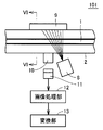
図1は、本発明の第1の実施の形態に係る計測装置の本体の構成を示す外観図である。
<First Embodiment>
[Configuration and basic operation]
FIG. 1 is an external view showing the configuration of the main body of the measuring apparatus according to the first embodiment of the present invention.
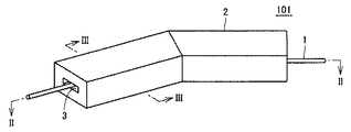
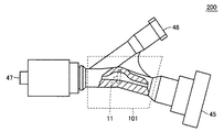
図1を参照して、計測装置101は、計測装置本体2を備え、計測装置本体2には可撓性を有する線状体1が貫通する貫通孔3が形成される。図1は、計測装置101が床面に設置された状態を示しており、図示していないが計測装置101の床面側に後述する光源8、レンズ10およびアレイセンサ11が配置されており、計測装置101の天井面側に後述する反射板9が配置されている。また、計測装置本体2は、たとえば透明体であり、光を透過することが可能な物質で形成される。
Referring to FIG. 1, a
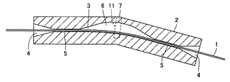
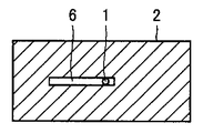
図2は、図1のII−II線による断面を示す断面図である。図3は、図1のIII−III線による断面を示す断面図である。 FIG. 2 is a cross-sectional view showing a cross section taken along line II-II in FIG. 3 is a cross-sectional view showing a cross section taken along line III-III in FIG.
図2を参照して、貫通孔3は、線状体1が貫通する出入口を大きくして挿入性を向上させるために、出入口にテーパ状の入出力ポート4を形成する。計測装置本体2の内部の拘束部5において、貫通孔3の直径は線状体1の直径よりもわずかに大きい(たとえば線状体1の直径の105%〜120%)。また、線状体1の長手軸方向に沿った貫通孔3の長さは線状体1の直径の数倍以上である。したがって、線状体1は、拘束部5において長手軸方向以外への動作を拘束される。
Referring to FIG. 2, the through-
貫通孔3は、線状体1に長手軸方向の圧縮力が作用していないとき、貫通孔3の内部において線状体1が所定の方向に湾曲し、線状体1に圧縮力が作用するとき、線状体1に長手軸方向の圧縮力が作用していないときと比べて線状体1が所定の方向へさらに湾曲するように形成される。このような構成により、線状体1に作用する長手軸方向の圧縮力が非常に小さい場合でも、正確に圧縮力を検出することができる。より詳細には、貫通孔3は、2つの拘束部5の間で曲がっており、線状体1は一方の壁に沿って曲がりながら貫通孔3を貫通する。また、貫通孔3は、2つの拘束部5の間で、線状体1が沿っていない壁側が広がって幅広部6を形成している。
In the
幅広部6は、紙面と平行方向における線状体1の動作を拘束しないように形成されている。なお、入出力ポート4および幅広部6において、紙面と垂直方向の貫通孔3の高さは線状体1の直径よりもわずかに大きく(たとえば線状体1の直径の105%〜120%)、線状体1に対して紙面と垂直方向の動作を拘束している。すなわち、入出力ポート4および幅広部6において、線状体1の長手軸方向に垂直な断面における貫通孔3の断面の形状は、長方形である。このような構成により、貫通孔3の内部における線状体1の湾曲方向を規定し、線状体1に長手軸方向の圧縮力が作用するときの線状体1の湾曲部の位置を決定している。
The
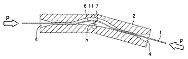
図4は、図2の断面図において、線状体1に圧縮力が作用し、計測装置本体2の内部において線状体1が湾曲している状態を示す図である。
FIG. 4 is a diagram illustrating a state in which a compressive force acts on the
図4を参照して、線状体1に長手軸方向の圧縮力Pが作用するとき、貫通孔3の内部の幅広部6において所定の方向へ、すなわち幅広部6において線状体1が沿っていない壁側へ向かって線状体1が湾曲する。線状体1の湾曲に伴い、湾曲の山の高さh、すなわち線状体1が沿っていた壁面から線状体1までの距離が大きくなる。
Referring to FIG. 4, when compressive force P in the longitudinal axis direction acts on
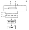
図5は、図1に示す設置状態で計測装置101を側面方向から見た図である。図6は、図5のVI−VI線による断面を示す断面図である。
FIG. 5 is a view of the measuring
図5および図6を参照して、計測装置101は、計測装置本体2と、光源(発光部)8と、反射板9と、レンズ10と、アレイセンサ(受光部)11と、画像処理部12と、変換部13とを備える。光源8は、たとえば赤外線LEDである。レンズ10は、たとえばセルフォック(登録商標)レンズである。アレイセンサ11は、たとえば一列に配置された複数個の受光素子を含む、1次元の光学式のアレイセンサである。アレイセンサ11および光源8と、反射板9とは、貫通孔3を挟んで対向する位置に配置される。
5 and 6, a measuring
計測装置101は、貫通孔3内の線状体1の像を光量変化としてとらえることにより、線状体1の湾曲度合いを検出する。
The measuring
より詳細には、光源8は、反射板9に光を照射する。反射板9は、光源8から照射された光を反射して貫通孔3に照射する。
More specifically, the
なお、貫通孔3に照射される光はムラを極力小さくすることが望ましい。このため、反射板9をたとえば白色として拡散性を高くし、光源8から照射される光のムラを低減することが望ましい。また、光源8自体に均一性が高いものを使用するか、光源8に拡散板を取り付ける構成が望ましい。
In addition, it is desirable that the light irradiated to the through-
アレイセンサ11における複数個の受光素子14は、貫通孔3を通過した光を受光し、受光した光を電気信号に変換して画像処理部12に出力する。受光素子14が出力する電気信号は、受光素子14の受光量を表わす。アレイセンサ11における複数個の受光素子は、線状体1の湾曲方向に順次配置されている。
The plurality of light receiving
画像処理部12は、アレイセンサ11における複数個の受光素子14から受けた電気信号に基づいて、アレイセンサ11における複数個の受光素子14の中から複数個の受光素子14を選択する。そして、画像処理部12は、選択した複数個の受光素子14の受光量を用いて所定の演算を行なうことにより、線状体1の湾曲度合いを検出する。
The
変換部13は、画像処理部12が検出した湾曲度合いを、線状体1に作用する圧縮力に変換する。
The
[動作]
次に、計測装置101が線状体1に作用する圧縮力を検出する際の動作について説明する。
[Operation]
Next, an operation when the measuring
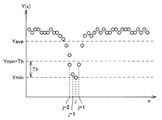
図7は、図4において幅広部6を詳細に示した図である。図8は、アレイセンサ11における複数個の受光素子14の位置Xと出力Y(X)との関係の一例を示す図である。
FIG. 7 is a view showing the
図7および図8を参照して、図7において左端に位置する受光素子14の出力が図8のグラフにおいて位置番号の最も小さい左端の点に対応し、図8において右端に位置する受光素子14の出力が図8のグラフにおいて位置番号の最も大きい右端の点に対応する。
7 and 8, the output of the
反射板9において反射された光を線状体1が遮ると受光素子14の受光量が小さくなる。図8に示す例では、位置番号jの受光素子14が線状体1に最も近いために受光量が最小となり、その出力Y(X)が最小値Yminとなる。また、位置番号jの受光素子14の近傍に位置する位置番号j−2,j−1,j+1の受光素子14の出力Y(X)が他の受光素子14の出力Y(X)と比べて小さくなっている。
When the
画像処理部12は、アレイセンサ11における複数個の受光素子14の出力Y(X)の最小値Yminを検出する。そして、画像処理部12は、最小値Yminに所定の閾値Thを加えた値未満の電気信号を出力する複数個の受光素子14を選択する。ここでは、画像処理部12は、位置番号j−2,j−1,j,j+1の受光素子14を選択する。そして、画像処理部12は、位置番号j−2,j−1,j,j+1の受光素子14の受光量すなわち出力Y(X)に以下の式(1)で表わされる演算を行なうことにより、位置番号Jを線状体1の湾曲度合いとして算出する。
The
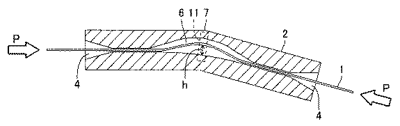
図8に示す例では、式(1)において、x1にはj−2が代入され、x2にはj+1が代入される。 In the example shown in FIG. 8, in Formula (1), j-2 is substituted for x1, and j + 1 is substituted for x2.
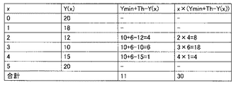
図9は、画像処理部12が行なう演算の具体例を示す図である。ここでは、アレイセンサ11における受光素子14の位置番号が0〜5であり、閾値Thが6である。
FIG. 9 is a diagram illustrating a specific example of the calculation performed by the
図9を参照して、位置番号0〜5の受光素子14の出力Y(0)〜Y(5)は、それぞれ20,18,12,10,15,20である。
Referring to FIG. 9, outputs Y (0) to Y (5) of
画像処理部12は、出力Y(0)〜Y(5)の中から、Y(3)=10を最小値Yminとして検出する。そして、画像処理部12は、最小値Yminである10に閾値Thである6を加えた16より小さい電気信号を出力する位置番号2〜4の受光素子14を選択する。そうすると、式(1)において分母が11となり、分子が30となる。したがって、線状体1の湾曲度合いを表わす位置番号Jは30/11≒2.73となる。すなわち、画像処理部12は、選択した複数個の受光素子14の受光量を用いて式(1)の演算を行なうことにより、アレイセンサ11の分解能を超える位置番号、すなわち線状体1の湾曲度合いを検出することができる。
The
変換部13は、線状体1に作用する長手軸方向の圧縮力Pと位置番号Jすなわち線状体1の湾曲度合いとの相関関係を予め計測した結果を記憶する。変換部13は、記憶している相関関係に基づいて、画像処理部12から受けた位置番号を圧縮力Pに変換する。
The
ところで、特許文献1記載のカテーテルでは、医療器具等の構成および操作が複雑であるという問題点があった。
By the way, in the catheter of
しかしながら、本発明の第1の実施の形態に係る計測装置では、線状体1に圧縮力が作用するとき、貫通孔3の内部において線状体1が所定の方向へ湾曲する。そして、画像処理部12は、アレイセンサ11における複数個の受光素子14の受光量に基づいて、アレイセンサ11における複数個の受光素子14の中から複数個の受光素子14を選択する。そして、画像処理部12は、選択した複数個の受光素子14の受光量を用いて所定の演算を行なうことにより、線状体1の湾曲度合いを検出する。そして、変換部13は、画像処理部12が検出した湾曲度合いを、線状体1に作用する圧縮力に変換する。このような構成により、術者の力覚に相当する、術者の手元付近におけるガイドワイヤの軸方向の圧縮荷重Pを検出することが可能となる。また、ガイドワイヤの先端に圧力センサを取り付ける必要がないため、手術の種類ごとにセンサ付きガイドワイヤ等を用意する必要がない。したがって、本発明の第1の実施の形態に係る計測装置では、医療器具等を簡易な構成で実現し、かつ操作の複雑化を防ぐことができる。
However, in the measuring apparatus according to the first embodiment of the present invention, when a compressive force acts on the
また、前述のようにガイドワイヤ先端に取り付けた圧力センサの出力と術者の挿入時の力覚とが必ずしも一致しないために、術者のガイドワイヤに対する力覚は実際にガイドワイヤを挿入している術者しか知ることができない。したがって、特許文献1記載のカテーテルでは、経験の少ない術者へ定量的な手技の伝授ができないという問題点がある。しかしながら、本発明の第1の実施の形態に係る計測装置では、線状体1に作用する圧縮力Pを計測することにより、熟練術者の操作を定量化することができ、経験の少ない術者の手技を早期に向上させることができる。
Further, as described above, since the output of the pressure sensor attached to the tip of the guide wire does not necessarily match the force sense at the time of insertion of the operator, the force sense of the operator on the guide wire is actually inserted by inserting the guide wire. Only the caster can know. Therefore, the catheter described in
アレイセンサ11は、図2等に示すように細長い形状である。図1に示すように計測装置101のアレイセンサ11側の面が床に設置される場合、計測装置101を安定して設置するためにはアレイセンサ11を筐体に収納し、筐体の幅をアレイセンサ11の幅よりも大きくする必要がある。ここで、本発明の第1の実施の形態に係る計測装置は、反射板9を備え、アレイセンサ11および光源8と、反射板9とは、貫通孔3を挟んで対向する位置に配置される構成である。このような構成により、アレイセンサ11を含む筐体に光源8を収納し、アレイセンサ11と光源8とを床面に対して平行に配置することで、収納効率を高め、計測装置101の高さ方向のサイズを小さくすることができる。
The
なお、計測装置101は、反射板9を備えない構成とすることも可能である。この場合、光源8は、貫通孔3における幅広部6に光を直接照射する。
Note that the measuring
また、本発明の第1の実施の形態に係る計測装置では、画像処理部12は、複数個の受光素子14の受光量に式(1)で表わされる演算を行なうことにより、位置番号Jを線状体1の湾曲度合いとして算出する構成であるとしたが、これに限定するものではない。画像処理部12は、受光量の最も小さい受光素子の位置番号をjとすると、位置番号j±αの受光素子、および位置番号jの受光素子の受光量に以下の式(2)で表わされる演算を行なうことにより、位置番号Jを線状体1の湾曲度合いとして算出する構成とすることができる。ここで、Ymaxはアレイセンサ11における複数個の受光素子14の出力Y(X)の最大値である。
Further, in the measurement apparatus according to the first embodiment of the present invention, the
次に、本発明の他の実施の形態について図面を用いて説明する。なお、図中同一または相当部分には同一符号を付してその説明は繰り返さない。 Next, another embodiment of the present invention will be described with reference to the drawings. In the drawings, the same or corresponding parts are denoted by the same reference numerals and description thereof will not be repeated.
<第2の実施の形態>
本実施の形態は、第1の実施の形態に係る計測装置に対して受光量をフィードバックする構成を追加した計測装置に関する。以下で説明する内容以外は第1の実施の形態に係る計測装置と同様である。
<Second Embodiment>
The present embodiment relates to a measurement apparatus in which a configuration for feeding back the amount of received light is added to the measurement apparatus according to the first embodiment. The contents other than those described below are the same as those of the measuring apparatus according to the first embodiment.
図10は、本発明の第2の実施の形態に係る計測装置の構成を示す図である。
図10を参照して、計測装置102は、計測装置101に対して、さらに制御部15を備える。
FIG. 10 is a diagram showing a configuration of a measurement apparatus according to the second embodiment of the present invention.
With reference to FIG. 10, the
制御部15は、アレイセンサ11における複数個の受光素子14から受けた電気信号の平均値Yaveを算出し、平均値Yaveが所定値となるように、光源8が照射する光の光量およびアレイセンサ11の感度のうちの少なくともいずれか一方を調整する。なお、制御部15は、アレイセンサ11における複数個の受光素子14の中から特定の受光素子14を選択し、選択した受光素子14の受光量に基づいて上記調整を行なってもよいし、アレイセンサ11における複数個の受光素子14から受けた電気信号の最大値または中央値が所定値となるように上記調整を行なってもよい。
The
光源8は、制御部15の制御に基づいて、反射板9に照射する光の量を変更する。アレイセンサ11は、制御部15の制御に基づいて、受光感度を変更する。たとえば、アレイセンサ11は、受光素子14の出力を増幅し、かつ制御部15から受けた制御信号に基づいて増幅率を変更する増幅器を含む。
The
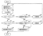
図11は、計測装置102が光源8の発光量を調整する際の動作手順を定めたフローチャートである。ここで、YtpはYaveの取るべき範囲の上限であり、YtmはYaveの取るべき範囲の下限である。
FIG. 11 is a flowchart that defines an operation procedure when the measuring
制御部15は、アレイセンサ11における複数個の受光素子14から受けた電気信号の平均値Yaveを算出する(S1およびS2)。
The
制御部15は、平均値YaveがYtm未満である場合(S3でYES)であって光源8の発光量を増加させることができるとき(S4でYES)には、光源8に制御信号を出力して光源8の発光量を増加させる(S5)。
When the average value Yave is less than Ytm (YES in S3) and the light emission amount of the
一方、制御部15は、平均値YaveがYtm以上であり(S3でNO)、かつYtpより大きい場合(S6でYES)であって光源8の発光量を減少させることができるとき(S7でYES)には、光源8に制御信号を出力して光源8の発光量を減少させる(S8)。
On the other hand, when the average value Yave is equal to or greater than Ytm (NO in S3) and greater than Ytp (YES in S6), the
制御部15は、平均値YaveがYtm以上であり(S3でNO)、かつYtp以下である場合(S6でNO)には、光量調整が正常終了したと判断する(S9)。
When the average value Yave is equal to or greater than Ytm (NO in S3) and equal to or less than Ytp (NO in S6), the
また、制御部15は、平均値YaveがYtm未満である場合(S3でYES)であって光源8の発光量を増加させることができないとき(S4でNO)、あるいは、平均値YaveがYtpより大きい場合(S6でYES)であって光源8の発光量を減少させることができないとき(S7でNO)には、光量調整が異常終了したと判断する(S10)。
The
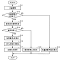
図12は、計測装置102の動作手順を定めたフローチャートである。
制御部15は、図11のフローチャートに示す光量調整を行なう(S11)。
FIG. 12 is a flowchart that defines the operation procedure of the measuring
The
画像処理部12は、光量調整が正常終了した場合には(S12でYES)、線状体1の有無判定を行なう(S13)。より詳細には、画像処理部12は、アレイセンサ11における複数個の受光素子14の出力Y(X)の最小値Yminを検出する。画像処理部12は、最小値Yminおよび平均値Yaveの差が所定値以上である場合には貫通孔3に線状体1が挿入されていると判断し、最小値Yminおよび平均値Yaveの差が所定値未満である場合には貫通孔3に線状体1が挿入されていないと判断する。
When the light amount adjustment is normally completed (YES in S12), the
画像処理部12は、貫通孔3に線状体1が挿入されていると判断した場合には(S14でYES)、第1の実施の形態に係る計測装置と同様の方法で、位置番号Jを線状体1の湾曲度合いとして算出する(S15)。
When the
変換部13は、画像処理部12から受けた位置番号Jを圧縮力Pに変換する(S16)。そして、変換部13は、図示しない表示部に圧縮力Pを表わす電気信号を出力することにより、表示部に圧縮力Pを表示する(S17)。
The
一方、画像処理部12は、光量調整が異常終了した場合には(S12でNO)、光量調整不能の旨を表示部に表示する(S18)。
On the other hand, when the light amount adjustment has ended abnormally (NO in S12), the
また、画像処理部12は、貫通孔3に線状体1が挿入されていないと判断した場合には(S14でNO)、計測装置102に線状体1が挿入されていない旨を表示部に表示する(S19)。
When the
したがって、本発明の第2の実施の形態に係る計測装置では、光源8の発光量およびアレイセンサ11の感度を最適化することで、アレイセンサ11が極細の線状体の像を正確に認識することができ、線状体に作用する圧縮力の検出性能を高めることができる。
Therefore, in the measuring apparatus according to the second embodiment of the present invention, the
次に、本発明の他の実施の形態について図面を用いて説明する。なお、図中同一または相当部分には同一符号を付してその説明は繰り返さない。 Next, another embodiment of the present invention will be described with reference to the drawings. In the drawings, the same or corresponding parts are denoted by the same reference numerals and description thereof will not be repeated.
<第3の実施の形態>
本実施の形態は、第1の実施の形態に係る計測装置に対して本体にマーカを取り付けた計測装置に関する。以下で説明する内容以外は第1の実施の形態に係る計測装置と同様である。
<Third Embodiment>
The present embodiment relates to a measurement apparatus in which a marker is attached to a main body with respect to the measurement apparatus according to the first embodiment. The contents other than those described below are the same as those of the measuring apparatus according to the first embodiment.
図13は、本発明の第3の実施の形態に係る計測装置の構成を示す図である。
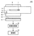
図13を参照して、計測装置103は、計測装置101に対して、さらにマーカ16を備える。
FIG. 13 is a diagram showing a configuration of a measuring apparatus according to the third embodiment of the present invention.
Referring to FIG. 13,
マーカ16は、計測装置本体2の、反射板9において反射されて受光素子14に照射される光を遮る位置に取り付けられる。
The
画像処理部12は、第1の実施の形態に係る計測装置と同様に、アレイセンサ11における複数個の受光素子14から受けた電気信号に基づいて、アレイセンサ11における複数個の受光素子14の中から複数個の受光素子14を選択する。そして、画像処理部12は、選択した複数個の受光素子14の受光量を用いて所定の演算を行なう。また、画像処理部12は、アレイセンサ11における複数個の受光素子14から受けた電気信号に基づいてマーカ16の像を認識する。そして、画像処理部12は、演算結果および認識したマーカ16の像に基づいて線状体1の湾曲度合いを検出する。
Similar to the measurement apparatus according to the first embodiment, the
なお、画像処理部12は、第1の実施の形態に係る計測装置と同様に式(1)を用いる構成に限定されるものではなく、単にアレイセンサ11における複数個の受光素子14から受けた電気信号に基づいて線状体1およびマーカ16の像を認識し、認識した線状体1の像およびマーカ16の像に基づいて線状体1の湾曲度合いを検出する構成であってもよい。
Note that the
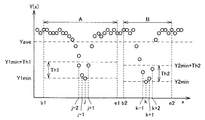
図14は、アレイセンサ11における複数個の受光素子14の位置Xと出力Y(X)との関係の一例を示す図である。ここでは、位置番号b1〜e1の範囲Aが線状体1の湾曲する領域に対応し、位置番号b2〜e2の範囲Bがマーカ16の取り付け領域に対応する。
FIG. 14 is a diagram illustrating an example of the relationship between the position X of the plurality of light receiving
範囲Aでは、反射板9において反射された光を線状体1が遮ると受光素子14の受光量が小さくなる。図14に示す例では、位置番号jの受光素子14が線状体1に最も近いために受光量が最小となり、その出力Y(X)が最小値Y1minとなる。また、位置番号jの受光素子14の近傍に位置する位置番号j−2,j−1,j+1の受光素子14の出力Y(X)が他の受光素子14の出力Y(X)と比べて小さくなっている。
In the range A, the amount of light received by the
範囲Bでは、反射板9において反射された光をマーカ16が遮ると受光素子14の受光量が小さくなる。図14に示す例では、位置番号kの受光素子14がマーカ16に最も近いために受光量が最小となり、その出力Y(X)が最小値Y2minとなる。また、位置番号kの受光素子14の近傍に位置する位置番号k−1,k+1,k+2の受光素子14の出力Y(X)が他の受光素子14の出力Y(X)と比べて小さくなっている。
In the range B, when the
画像処理部12は、範囲AおよびBにおいて、アレイセンサ11における複数個の受光素子14の出力Y(X)の最小値Y1minおよびY2minをそれぞれ検出する。そして、画像処理部12は、最小値Y1minに所定の閾値Th1を加えた値未満の電気信号を出力する複数個の受光素子14、および最小値Y2minに所定の閾値Th2を加えた値未満の電気信号を出力する複数個の受光素子14をそれぞれ選択する。ここでは、画像処理部12は、位置番号j−2,j−1,j,j+1の受光素子14、および位置番号k−1,k,k+1,k+2の受光素子14をそれぞれ選択する。そして、画像処理部12は、選択した受光素子14の受光量すなわち出力Y(X)に以下の式で表わされる演算を行なうことにより、位置番号JおよびKを算出し、位置番号Jを位置番号Kおよび定数constを用いて補正した結果である位置番号Gを線状体1の湾曲度合いとして算出する。
In the ranges A and B, the
ここで、アレイセンサ11およびセンサ本体2を組み付ける場合、アレイセンサ11およびセンサ本体2の組み付け位置に製品間でばらつきが生じる。組みつけ位置のばらつきが生じると、画像処理部12の算出する位置番号Jにばらつきが生じ、製品間で検出性能のばらつきが生じてしまう。そして、アレイセンサ11およびセンサ本体2は、いくつかの部品を介して組み付けられるため、精度よく組み付けるのは困難である。このような問題点を解決するため、圧縮力Pがゼロの場合における位置番号Jが製品ごとに同じになるように、変換部13の、圧縮力Pと位置番号Jとの相関関係を製品ごとに調整するか、あるいは画像処理部12の受光量計算においてオフセットを設け、製品ごとにオフセット値を調整することが考えられるが、計測装置の生産時間および生産コストが増大してしまう。
Here, when the
しかしながら、本発明の第3の実施の形態に係る計測装置では、マーカ16をセンサ本体2に取り付ける。マーカ16および貫通孔3は、一体的に加工すること、あるいは同時に成型することが可能であるため、マーカ16および貫通孔3の位置関係の精度は非常に高くなる。そして、画像処理部12は、マーカ16の像を基準として線状体1の湾曲度合いを検出するため、製品間で湾曲度合いの検出結果にばらつきが生じることを防ぐことができる。すなわち、所定の圧縮力が線状体1に作用している場合における、画像処理部12の算出する位置番号Jの製品間のばらつきを防ぐことができ、製品間の検出性能のばらつきを防ぐことができる。そして、上記のような相関関係の調整およびオフセット値の調整が不要となり、計測装置の生産時間および生産コストの増大を防ぐことができる。
However, in the measurement device according to the third embodiment of the present invention, the
なお、位置番号Kの算出方法は式(3)によるものに限定されるものではなく、たとえば範囲Bにおける、アレイセンサ11における複数個の受光素子14のうち、電気信号が最小となる受光素子の位置番号をそのまま位置番号Kとする構成であってもよい。
Note that the method of calculating the position number K is not limited to that according to the expression (3). For example, among the plurality of light receiving
次に、本発明の他の実施の形態について図面を用いて説明する。なお、図中同一または相当部分には同一符号を付してその説明は繰り返さない。 Next, another embodiment of the present invention will be described with reference to the drawings. In the drawings, the same or corresponding parts are denoted by the same reference numerals and description thereof will not be repeated.
<第4の実施の形態>
本実施の形態は、第1の実施の形態に係る計測装置に対してアレイセンサの構成を変更した計測装置に関する。以下で説明する内容以外は第1の実施の形態に係る計測装置と同様である。
<Fourth embodiment>
The present embodiment relates to a measurement apparatus in which the configuration of the array sensor is changed with respect to the measurement apparatus according to the first embodiment. The contents other than those described below are the same as those of the measuring apparatus according to the first embodiment.
図15は、本発明の第4の実施の形態に係る計測装置の構成を示す図である。
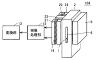
図15を参照して、計測装置104は、計測装置101に対して、アレイセンサ11の代わりにアレイセンサ(受光部)21および22と、セルフォック(登録商標)レンズ10の代わりにセルフォック(登録商標)レンズ23および24とを備える。
FIG. 15 is a diagram showing a configuration of a measuring apparatus according to the fourth embodiment of the present invention.
Referring to FIG. 15, measuring
アレイセンサ21および22は、たとえば一列に配置された複数個の受光素子を含む、1次元の光学式のアレイセンサである。
The
画像処理部12は、第1の実施の形態に係る計測装置と同様に、アレイセンサ21および22における複数個の受光素子14から受けた電気信号に基づいて線状体1の湾曲度合いを検出する。
The
このような構成により、線状体1の湾曲度合いの検出精度を高めることができる。
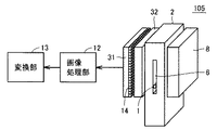
図16は、本発明の第4の実施の形態に係る計測装置の変形例の構成を示す図である。
With such a configuration, the detection accuracy of the degree of bending of the
FIG. 16 is a diagram showing a configuration of a modified example of the measuring apparatus according to the fourth embodiment of the present invention.
図16を参照して、計測装置105は、計測装置101に対して、アレイセンサ11の代わりにアレイセンサ(受光部)31と、レンズ10の代わりにレンズ32とを備える。
Referring to FIG. 16,
アレイセンサ31は、たとえば行列状に配置された複数個の受光素子を含む、2次元の光学式のアレイセンサである。レンズ32は、たとえばセルフォック(登録商標)レンズである。
The
画像処理部12は、アレイセンサ31における複数個の受光素子14から受けた電気信号に基づいて線状体1の像を認識し、画像処理を用いた特徴抽出およびパターンマッチング等を行なうことにより、線状体1の湾曲度合いを検出する。
The
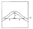
図17は、本発明の第4の実施の形態に係る計測装置が線状体1の湾曲度合いを算出する方法を示す図である。Cは、画像処理部12の認識した線状体1の像である。
FIG. 17 is a diagram illustrating a method by which the measuring device according to the fourth embodiment of the present invention calculates the degree of bending of the
図17を参照して、画像処理部12は、像Cの湾曲部の頂点から横軸方向に距離X離れた部分における像Cと、湾曲部の頂点との縦軸方向の差Yを検出することにより、線状体1の湾曲度合いを検出する。
Referring to FIG. 17, the
このような構成により、アレイセンサ11およびセンサ本体2の組み付け位置に製品間でばらつきが生じても、画像処理部12の算出する位置番号Jに製品間でばらつきが生じることを防ぐことができる。なお、図15に示す計測装置104でも、複数個のアレイセンサを使用することから、図16に示す計測装置105と同様に、画像処理部12の算出する位置番号Jにばらつきが生じることを防ぐことができる。
With such a configuration, even if the assembly position of the
したがって、本発明の第4の実施の形態に係る計測装置では、本発明の第3の実施の形態に係る計測装置のようにマーカ16を備える必要がなく、構成の簡易化および画像処理部12の処理の簡易化を図ることができる。
Therefore, the measurement apparatus according to the fourth embodiment of the present invention does not need to include the
次に、本発明の他の実施の形態について図面を用いて説明する。なお、図中同一または相当部分には同一符号を付してその説明は繰り返さない。 Next, another embodiment of the present invention will be described with reference to the drawings. In the drawings, the same or corresponding parts are denoted by the same reference numerals and description thereof will not be repeated.
<第5の実施の形態>
本実施の形態は、第1の実施の形態に係る計測装置に対して反射板の構成を変更した計測装置に関する。以下で説明する内容以外は第1の実施の形態に係る計測装置と同様である。
<Fifth embodiment>
The present embodiment relates to a measurement apparatus in which the configuration of the reflector is changed with respect to the measurement apparatus according to the first embodiment. The contents other than those described below are the same as those of the measuring apparatus according to the first embodiment.
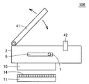
図18は、本発明の第5の実施の形態に係る計測装置の構成を示す図である。
図18を参照して、計測装置106は、計測装置101に対して、反射板9の代わりに反射板41と、固定具42とを備える。アレイセンサ11および光源8と、反射板41とは、貫通孔3を挟んで対向する位置に配置される。
FIG. 18 is a diagram showing a configuration of a measuring apparatus according to the fifth embodiment of the present invention.
Referring to FIG. 18, measuring
反射板41は、可動式である。より詳細には、反射板41は、線状体1の貫通方向と略垂直な方向から貫通孔3を視認できる位置に移動可能である。ユーザは、線状体1に作用する圧縮力Pを計測する場合、反射板41を固定具42の位置に固定する。このような構成により、ユーザは、線状体1を観察しながら貫通孔3に挿入することが可能となり、操作性を向上させることができる。
The
なお、反射板41を可動式とするのではなく、たとえば図16に示す光源8を可動式とする構成であっても同様の効果を奏することができる。
The same effect can be obtained even if the
ただし、反射板41を可動式とする構成は、電気配線の必要な光源8を可動式にする構成と比べて、計測装置の構成の簡易化を図り、かつ光のムラの発生を防ぐことができる望ましい構成である。
However, the configuration in which the reflecting
次に、本発明の他の実施の形態について図面を用いて説明する。なお、図中同一または相当部分には同一符号を付してその説明は繰り返さない。 Next, another embodiment of the present invention will be described with reference to the drawings. In the drawings, the same or corresponding parts are denoted by the same reference numerals and description thereof will not be repeated.
<第6の実施の形態>
次に、本発明の計測装置を実用化する例として、体内の管の中へ挿入される線状の医療器具である線状体に作用する長手軸方向の圧縮力を計測する計測装置が、他の医療機器に組み込まれて使用される例を示す。
<Sixth Embodiment>
Next, as an example of putting the measuring device of the present invention into practical use, a measuring device that measures the compressive force in the longitudinal axis direction acting on a linear body that is a linear medical instrument inserted into a body tube, An example in which it is incorporated into another medical device will be shown.
図19は、本発明の第6の実施の形態に係るYコネクタの構成を示す図である。
図19を参照して、Yコネクタ(医療装置)200は、計測装置101と、入力ポート45および46と、出力ポート47とを備える。
FIG. 19 is a diagram showing a configuration of a Y connector according to the sixth embodiment of the present invention.
Referring to FIG. 19, a Y connector (medical device) 200 includes a
計測装置101は、Yコネクタ200の内部の、入力ポート45と出力ポート47とを連通する通路に組み込まれている。線状体1は、たとえば、血管および尿管等の体内の管に挿入されるガイドワイヤおよびカテーテル、ならびに動脈瘤を塞栓するための塞栓用コイルが先端に付いたワイヤ等、線状の医療器具である。線状体1は、入力ポート45側からの操作によって体内の目的部位まで誘導される。
The measuring
線状体1に作用する長手軸方向の圧縮力の増加を計測することにより、圧縮力の反力すなわち線状体1が体内の管に作用する荷重を計測することができる。すなわち、医療器具の先端が管の内壁に接触することを検知することができ、体内の管に過大な荷重が作用することを防ぐことができる。
By measuring the increase in the compressive force in the longitudinal axis direction acting on the
また、計測装置101がYコネクタ200に組み込まれているため、Yコネクタ200の入力ポート45から線状体1を操作し、入力ポート46から薬剤を注入することができる。たとえば、カテーテルとガイドワイヤとの摩擦を低減するための生理食塩水を入力ポート46から注入することができる。また、血管の中に挿入したカテーテルを人体外部から目的部位まで誘導した後に、入力ポート46から血管造影剤を注入して、血管造影剤を体内の目的部位に注入することができる。
Further, since the measuring
次に、本発明の他の実施の形態について図面を用いて説明する。なお、図中同一または相当部分には同一符号を付してその説明は繰り返さない。 Next, another embodiment of the present invention will be described with reference to the drawings. In the drawings, the same or corresponding parts are denoted by the same reference numerals and description thereof will not be repeated.
<第7の実施の形態>
図20は、本発明の第7の実施の形態に係る訓練装置の構成を示す図である。
<Seventh embodiment>
FIG. 20 is a diagram showing a configuration of a training apparatus according to the seventh embodiment of the present invention.
図20を参照して、訓練装置300は、計測装置101と、ガイドワイヤ(線状体)51と、カテーテル52と、シミュレータ54と、ケーブル56と、提示部57とを備える。
Referring to FIG. 20,
カテーテル52は、計測装置101に接続され、計測装置101を通過したガイドワイヤ51が挿入される。
The
ガイドワイヤ51を把持する術者53がガイドワイヤ51をシミュレータ54の内部へ進めるためにガイドワイヤ51に圧縮力をかけると、その圧縮力が提示部57によって表示される。
When the operator 53 holding the
シミュレータ54は、人体を模擬するものであり、人体の管の透視画像と同等のものを表示する。医療装置の訓練を行なっている術者53はシミュレータ54の表示画像を見ながらガイドワイヤ51を操作する。シミュレータ54は、挿入されたガイドワイヤ51に対する挿入抵抗を変化させる。操作時の抵抗力すなわち、計測装置101で計測されるガイドワイヤ51に作用する圧縮力は、提示部57に表示されるとともに、ケーブル56を介してシミュレータ54にも伝達される。シミュレータ54は、伝達された圧縮荷重に基づいてガイドワイヤ51の挿入抵抗を変更する。
The
なお、図20では計測装置101およびシミュレータ54が分離されているが、計測装置101およびシミュレータ54が一体化される構成であってもよい。また、提示部57の代わりにシミュレータ54の表示する模擬透視画像にガイドワイヤ51に作用する圧縮力を追加表示する構成であってもよい。
In FIG. 20, the
このような構成により、熟練術者の操作を定量化することができ、経験の少ない術者の手技を早期に向上させることができる。また、手術中の記録として、透視画像とともに、術者の操作を記録することができる。 With such a configuration, the operation of the skilled operator can be quantified, and the procedure of the less experienced operator can be improved at an early stage. Further, the operator's operation can be recorded together with the fluoroscopic image as a record during the operation.
今回開示された実施の形態はすべての点で例示であって制限的なものではないと考えられるべきである。本発明の範囲は上記した説明ではなくて特許請求の範囲によって示され、特許請求の範囲と均等の意味および範囲内でのすべての変更が含まれることが意図される。 The embodiment disclosed this time should be considered as illustrative in all points and not restrictive. The scope of the present invention is defined by the terms of the claims, rather than the description above, and is intended to include any modifications within the scope and meaning equivalent to the terms of the claims.
1 線状体、2 計測装置本体、3 貫通孔、4 入出力ポート、5 拘束部、6 幅広部、8 光源(発光部)、9,41 反射板、10,32 レンズ、11,21,22,31 アレイセンサ(受光部)、12 画像処理部、13 変換部、14 受光素子、15 制御部、16 マーカ、23,24 セルフォック(登録商標)レンズ、42 固定具、45,46 入力ポート、47 出力ポート、51 ガイドワイヤ(線状体)、52 カテーテル、54 シミュレータ、56 ケーブル、57 提示部、101〜106 計測装置、200 Yコネクタ(医療装置)、300 訓練装置。
DESCRIPTION OF
Claims (12)
前記線状体が貫通する貫通孔が形成される本体を備え、
前記線状体に前記圧縮力が作用するとき、前記貫通孔の内部において前記線状体が所定の方向へ湾曲し、さらに、
前記貫通孔に光を照射する発光部と、
前記貫通孔を通過した光を受光する複数個の受光素子を含む受光部と、
前記受光部における受光素子の受光量に基づいて前記受光部における受光素子の中から複数個の受光素子を選択し、前記選択した複数個の受光素子の受光量を用いて所定の演算を行なうことにより、前記線状体の湾曲度合いを検出する画像処理部と、
前記検出された湾曲度合いを、前記線状体に作用する前記圧縮力に変換する変換回路とを備える計測装置。 A measuring device that measures a compressive force acting on a flexible linear body,
A main body in which a through-hole through which the linear body passes is formed,
When the compressive force acts on the linear body, the linear body is curved in a predetermined direction inside the through hole, and
A light emitting unit for irradiating the through hole with light;
A light receiving unit including a plurality of light receiving elements for receiving light that has passed through the through hole;
A plurality of light receiving elements are selected from the light receiving elements in the light receiving unit based on the amount of light received by the light receiving elements in the light receiving unit, and a predetermined calculation is performed using the received light amounts of the selected plurality of light receiving elements. An image processing unit for detecting the degree of curvature of the linear body,
A measuring apparatus comprising: a conversion circuit that converts the detected degree of bending into the compressive force acting on the linear body.
反射部を備え、
前記発光部は、前記反射部に光を照射して反射させることにより前記貫通孔に光を照射する請求項1記載の計測装置。 The measuring device further includes:
With a reflective part,
The measurement device according to claim 1, wherein the light emitting unit irradiates the through hole with light by irradiating the reflective unit with light and reflecting the light.
前記受光部における受光素子の受光量に基づいて、前記発光部が照射する光の光量および前記受光部における受光素子の感度のうちの少なくともいずれか一方を調整する制御部を備える請求項1記載の計測装置。 The measuring device further includes:
The control part which adjusts at least any one of the light quantity of the light which the said light emission part irradiates, and the sensitivity of the light receiving element in the said light receiving part based on the light reception amount of the light receiving element in the said light receiving part. Measuring device.
前記本体における、前記発光部から前記受光素子に照射される光を遮る位置に取り付けられるマーカを備え、
前記画像処理部は、さらに、前記受光部における受光素子の受光量に基づいて前記マーカの像を認識し、前記演算結果および前記認識したマーカの像に基づいて前記線状体の湾曲度合いを検出する請求項1記載の計測装置。 The measuring device further includes:
In the main body, comprising a marker attached to a position that blocks light emitted from the light emitting unit to the light receiving element,
The image processing unit further recognizes the marker image based on the amount of light received by the light receiving element in the light receiving unit, and detects the degree of curvature of the linear body based on the calculation result and the recognized marker image. The measuring device according to claim 1.
前記線状体が貫通する貫通孔が形成される本体を備え、
前記線状体に前記圧縮力が作用するとき、前記貫通孔の内部において前記線状体が所定の方向へ湾曲し、さらに、
前記貫通孔に光を照射する発光部と、
前記貫通孔を通過した光を受光する複数個の受光素子を含む受光部と、
前記本体における、前記発光部から前記受光素子に照射される光を遮る位置に取り付けられるマーカとを備え、
前記受光部における受光素子の受光量に基づいて前記線状体の像を認識し、かつ前記受光部における受光素子の受光量に基づいて前記マーカの像を認識し、前記認識した前記線状体の像および前記マーカの像に基づいて前記線状体の湾曲度合いを検出する画像処理部と、
前記検出された湾曲度合いを、前記線状体に作用する前記圧縮力に変換する変換回路とを備える計測装置。 A measuring device that measures a compressive force acting on a flexible linear body,
A main body in which a through-hole through which the linear body passes is formed,
When the compressive force acts on the linear body, the linear body is curved in a predetermined direction inside the through hole, and
A light emitting unit for irradiating the through hole with light;
A light receiving unit including a plurality of light receiving elements for receiving light that has passed through the through hole;
In the main body, comprising a marker attached to a position that blocks the light irradiated from the light emitting unit to the light receiving element,
The linear body image is recognized based on the amount of light received by the light receiving element in the light receiving unit, and the marker image is recognized based on the amount of light received by the light receiving element in the light receiving unit. An image processing unit for detecting a degree of curvature of the linear body based on the image of the marker and the image of the marker;
A measuring apparatus comprising: a conversion circuit that converts the detected degree of bending into the compressive force acting on the linear body.
Priority Applications (1)
| Application Number | Priority Date | Filing Date | Title |
|---|---|---|---|
| JP2006190534A JP4895105B2 (en) | 2006-07-11 | 2006-07-11 | Measuring device and medical device and training device provided with the same |
Applications Claiming Priority (1)
| Application Number | Priority Date | Filing Date | Title |
|---|---|---|---|
| JP2006190534A JP4895105B2 (en) | 2006-07-11 | 2006-07-11 | Measuring device and medical device and training device provided with the same |
Publications (2)
| Publication Number | Publication Date |
|---|---|
| JP2008020249A true JP2008020249A (en) | 2008-01-31 |
| JP4895105B2 JP4895105B2 (en) | 2012-03-14 |
Family
ID=39076305
Family Applications (1)
| Application Number | Title | Priority Date | Filing Date |
|---|---|---|---|
| JP2006190534A Expired - Fee Related JP4895105B2 (en) | 2006-07-11 | 2006-07-11 | Measuring device and medical device and training device provided with the same |
Country Status (1)
| Country | Link |
|---|---|
| JP (1) | JP4895105B2 (en) |
Cited By (2)
| Publication number | Priority date | Publication date | Assignee | Title |
|---|---|---|---|---|
| WO2011033985A1 (en) * | 2009-09-15 | 2011-03-24 | 国立大学法人 名古屋工業大学 | Measurement device, medical device, training device, and measurement method |
| JP5783904B2 (en) * | 2009-10-14 | 2015-09-24 | 国立大学法人 名古屋工業大学 | Insertion device and training device |
Citations (4)
| Publication number | Priority date | Publication date | Assignee | Title |
|---|---|---|---|---|
| JPS54135944A (en) * | 1978-04-14 | 1979-10-22 | Hitachi Ltd | Operation controlling method of power plant |
| JPS5690147A (en) * | 1979-12-19 | 1981-07-22 | Hitachi Ltd | Roller chain driving apparatus |
| JPH04285839A (en) * | 1991-03-14 | 1992-10-09 | Nkk Corp | Subsidence control method for buried piping |
| JPH0915072A (en) * | 1995-06-28 | 1997-01-17 | Casio Comput Co Ltd | Pressing force detector |
-
2006
- 2006-07-11 JP JP2006190534A patent/JP4895105B2/en not_active Expired - Fee Related
Patent Citations (4)
| Publication number | Priority date | Publication date | Assignee | Title |
|---|---|---|---|---|
| JPS54135944A (en) * | 1978-04-14 | 1979-10-22 | Hitachi Ltd | Operation controlling method of power plant |
| JPS5690147A (en) * | 1979-12-19 | 1981-07-22 | Hitachi Ltd | Roller chain driving apparatus |
| JPH04285839A (en) * | 1991-03-14 | 1992-10-09 | Nkk Corp | Subsidence control method for buried piping |
| JPH0915072A (en) * | 1995-06-28 | 1997-01-17 | Casio Comput Co Ltd | Pressing force detector |
Cited By (5)
| Publication number | Priority date | Publication date | Assignee | Title |
|---|---|---|---|---|
| WO2011033985A1 (en) * | 2009-09-15 | 2011-03-24 | 国立大学法人 名古屋工業大学 | Measurement device, medical device, training device, and measurement method |
| US20120174686A1 (en) * | 2009-09-15 | 2012-07-12 | Hideo Fujimoto | Measurement device, medical device, training device, and measurement method |
| JPWO2011033985A1 (en) * | 2009-09-15 | 2013-02-14 | 国立大学法人 名古屋工業大学 | Measuring device, medical device, training device, and measuring method |
| EP2479547A4 (en) * | 2009-09-15 | 2014-01-22 | Nat Univ Corp Nagoya Inst Tech | MEASURING DEVICE, MEDICAL DEVICE, DRIVING DEVICE, AND MEASURING METHOD |
| JP5783904B2 (en) * | 2009-10-14 | 2015-09-24 | 国立大学法人 名古屋工業大学 | Insertion device and training device |
Also Published As
| Publication number | Publication date |
|---|---|
| JP4895105B2 (en) | 2012-03-14 |
Similar Documents
| Publication | Publication Date | Title |
|---|---|---|
| JP4878513B2 (en) | Apparatus and method for measuring compressive force of flexible linear body | |
| JP4878526B2 (en) | Apparatus for measuring compressive force of flexible linear body | |
| JP6431678B2 (en) | Insertion shape detection device | |
| CN107529939B (en) | Insertion/extraction device, direct operation estimation method of insertion unit, and storage medium for non-transitory storage of direct operation estimation program of insertion unit | |
| US11857157B2 (en) | Flexible tube insertion support apparatus, flexible tube insertion apparatus, and flexible tube insertion method | |
| EP2957212A1 (en) | Relative position detection system for tube-like device, and endoscope device | |
| WO2011033985A1 (en) | Measurement device, medical device, training device, and measurement method | |
| US20150292974A1 (en) | Calibration device and calibration method for measurement instrument | |
| JP4895105B2 (en) | Measuring device and medical device and training device provided with the same | |
| CN105050476B (en) | Insertion apparatus | |
| JP4963067B2 (en) | Compressive force measuring device | |
| JPH10286221A (en) | Shape detecting device for endoscope | |
| JP4905691B2 (en) | Apparatus for measuring compressive force of flexible linear body | |
| JP2008064507A (en) | Apparatus and method for measuring force acting on flexible linear body | |
| US11503981B2 (en) | Flexible tube insertion apparatus and flexible tube insertion method | |
| JP2017026348A (en) | Measuring device, medical device, medical operation training device | |
| JP5190869B2 (en) | Measuring device | |
| JP2007202675A (en) | SENSOR AND MEDICAL DEVICE AND TRAINING DEVICE EQUIPPED WITH SAME | |
| JP2014073318A (en) | Conversion adaptor, measurement unit, medical device, and training device | |
| JP2003052615A (en) | Flexible electronic endoscope device |
Legal Events
| Date | Code | Title | Description |
|---|---|---|---|
| A621 | Written request for application examination |
Free format text: JAPANESE INTERMEDIATE CODE: A621 Effective date: 20090611 |
|
| A977 | Report on retrieval |
Free format text: JAPANESE INTERMEDIATE CODE: A971007 Effective date: 20111116 |
|
| TRDD | Decision of grant or rejection written | ||
| A01 | Written decision to grant a patent or to grant a registration (utility model) |
Free format text: JAPANESE INTERMEDIATE CODE: A01 Effective date: 20111122 |
|
| A01 | Written decision to grant a patent or to grant a registration (utility model) |
Free format text: JAPANESE INTERMEDIATE CODE: A01 |
|
| A61 | First payment of annual fees (during grant procedure) |
Free format text: JAPANESE INTERMEDIATE CODE: A61 Effective date: 20111214 |
|
| R150 | Certificate of patent or registration of utility model |
Free format text: JAPANESE INTERMEDIATE CODE: R150 Ref document number: 4895105 Country of ref document: JP Free format text: JAPANESE INTERMEDIATE CODE: R150 |
|
| FPAY | Renewal fee payment (event date is renewal date of database) |
Free format text: PAYMENT UNTIL: 20150106 Year of fee payment: 3 |
|
| R250 | Receipt of annual fees |
Free format text: JAPANESE INTERMEDIATE CODE: R250 |
|
| R250 | Receipt of annual fees |
Free format text: JAPANESE INTERMEDIATE CODE: R250 |
|
| R250 | Receipt of annual fees |
Free format text: JAPANESE INTERMEDIATE CODE: R250 |
|
| R250 | Receipt of annual fees |
Free format text: JAPANESE INTERMEDIATE CODE: R250 |
|
| R250 | Receipt of annual fees |
Free format text: JAPANESE INTERMEDIATE CODE: R250 |
|
| LAPS | Cancellation because of no payment of annual fees |