JP2008009897A - Vector graphic drawing apparatus and program thereof - Google Patents
Vector graphic drawing apparatus and program thereof Download PDFInfo
- Publication number
- JP2008009897A JP2008009897A JP2006181921A JP2006181921A JP2008009897A JP 2008009897 A JP2008009897 A JP 2008009897A JP 2006181921 A JP2006181921 A JP 2006181921A JP 2006181921 A JP2006181921 A JP 2006181921A JP 2008009897 A JP2008009897 A JP 2008009897A
- Authority
- JP
- Japan
- Prior art keywords
- edge
- scan line
- unit
- sub
- intersection
- Prior art date
- Legal status (The legal status is an assumption and is not a legal conclusion. Google has not performed a legal analysis and makes no representation as to the accuracy of the status listed.)
- Granted
Links
Images


Landscapes
- Image Generation (AREA)
Abstract
【課題】多大な計算量を要することなく高速な描画を実行することのできるベクトル図形描画装置を得る。
【解決手段】交点算出部2は、エッジ分割部1が生成したエッジとスキャンラインとの交点座標をサブピクセル精度で求めた値をエッジデータとして算出し、エッジデータリスト3に登録する。マスク生成部4は、エッジデータリスト3からエッジデータをサブスキャンライン単位で取得し、図形のマスク情報を生成する。内外判定部5は、マスク生成部4が生成したマスク情報を元に、図形の内外判定を行ってカバレッジ情報に変換する。塗潰し処理部6は、カバレッジ情報に基づき、図形の内部と判定された領域に対して塗潰し処理を実行する。
【選択図】図1A vector graphic drawing apparatus capable of performing high-speed drawing without requiring a large amount of calculation.
An intersection calculation unit calculates, as edge data, a value obtained by subpixel accuracy of an intersection coordinate between an edge generated by an edge division unit and a scan line, and registers it in an edge data list. The mask generation unit 4 acquires edge data from the edge data list 3 in units of sub-scan lines, and generates figure mask information. The inside / outside determination unit 5 performs inside / outside determination of a figure based on the mask information generated by the mask generation unit 4 and converts the figure into coverage information. The paint processing unit 6 performs paint processing on an area determined to be inside the figure based on the coverage information.
[Selection] Figure 1
Description
この発明は、ベクトル図形を描画するベクトル図形描画装置及びこの機能をコンピュータに実現させるベクトル図形描画装置のプログラムに関するものである。 The present invention relates to a vector graphic drawing apparatus for drawing a vector graphic and a program of a vector graphic drawing apparatus for causing a computer to realize this function.
従来、ベクトル図形を描画する図形描画装置においては、輪郭線のデータが曲線(ベジェ曲線等)で与えられた場合には、曲線を微小な線分(エッジ)に分割した後、多角形の描画と同様の手法で描画されるのが一般的である。エッジの分割数を増加させるほど、ベクトル図形の輪郭を曲線に近いものに近似できるが、頂点数が増大し複雑な図形となってしまう場合が多い。 Conventionally, in a graphic drawing apparatus that draws a vector graphic, when contour data is given by a curve (a Bezier curve or the like), a polygon is drawn after dividing the curve into minute line segments (edges). It is common to draw with the same method. As the number of edge divisions increases, the contour of a vector figure can be approximated to a curve that is close to a curve, but the number of vertices increases and the figure often becomes complex.
また、ベクトル図形の輪郭線が途中で交差するような場合には、図形の内外を区別するため一般に、イーブンオッド規則、ノンゼロ規則の2つの塗潰し規則が定められている。これらの規則に対応する方法の例としては、オーダードエッジリスト方式があり、走査線に交差する輪郭線を抽出し、この交差する位置を走査方向にソートして、交差する順番に走査線を辿り、交差位置に辿り着いた場合に、輪郭線のベクトル方向によって加算器に+1(または−1)し、加算結果に従って走査線方向に向かって塗潰しを行うものが提案されている。この方式では、X座標ソートに多大な負荷を必要とするため、例えば特許文献1で示されているように、傾き情報の比較を行うことでソート処理の負荷を削減する方式が開示されている。
In addition, when the outline of a vector graphic intersects in the middle, generally two painting rules of an even odd rule and a non-zero rule are defined in order to distinguish the inside and outside of the graphic. As an example of a method corresponding to these rules, there is an ordered edge list method, which extracts contour lines intersecting the scanning lines, sorts the intersecting positions in the scanning direction, and sets the scanning lines in the intersecting order. In the case of reaching the intersection position, the adder is incremented by +1 (or -1) according to the vector direction of the contour line, and the painting is performed in the scanning line direction according to the addition result. In this method, since a large load is required for X coordinate sorting, as shown in
また、ベクトル図形の輪郭部分にジャギーが発生せず滑らかに表示されるようなベクトル図形を得るためには、アンチエイリアス処理が必要である。このようなアンチエイリアス処理に関する技術として、例えば特許文献2では、ベクトル図形の輪郭線の、サブピクセル分割法によるアンチエイリアス処理の方法として、エッジ部分にある判定されたピクセルのみ濃度を算出し、エッジに挟まれた部分は最高濃度値で設定することにより、アンチエイリアス処理を効率化する手法について開示されている。
Further, in order to obtain a vector graphic that can be displayed smoothly without jaggies in the contour portion of the vector graphic, anti-aliasing processing is necessary. As a technique related to such anti-aliasing, for example, in
オーダードエッジリスト方式による多角形描画方式では、輪郭線との交点を走査線毎に毎回抽出し、その交点を走査方向にソートしなければならず、この処理に大きく処理時間を割いてしまうという課題があった。このような課題に対して、例えば、特許文献1に開示される技術においても、ソート回数は削減されても、複雑な図形を描画する場合には、依然として処理負荷を要するという問題点があった。
In the polygon drawing method based on the ordered edge list method, the intersection with the contour line must be extracted for each scanning line, and the intersection must be sorted in the scanning direction, which greatly reduces processing time. There was a problem. For example, even in the technique disclosed in
また、特許文献2に開示される技術においても、交点X座標値の小さい順に配列する必要があり、1ライン上の交点数が増大した場合には描画処理の度に多大なソート処理を必要とするという課題がある。更に、ノンゼロ規則の塗潰しへの対応については開示されていない。
このように、従来のベクトル図形描画技術では、多大な計算量を要することなく高速な描画を実行することが困難であった。
Also, in the technique disclosed in
Thus, with the conventional vector graphic drawing technique, it is difficult to execute high-speed drawing without requiring a large amount of calculation.
この発明は上記のような課題を解決するためになされたもので、多大な計算量を要することなく高速な描画を実行することのできるベクトル図形描画装置及びそのプログラムを得ることを目的とする。 The present invention has been made to solve the above-described problems, and an object of the present invention is to obtain a vector graphic drawing apparatus and its program capable of executing high-speed drawing without requiring a large amount of calculation.
この発明に係るベクトル図形描画装置は、ベクトル図形のデータにおける曲線を微小な線分であるエッジに分割するエッジ分割部と、エッジ分割部が生成したエッジとスキャンラインとの交点座標をサブピクセル精度で求めた値をエッジデータとして算出する交点算出部と、算出されたエッジデータをサブスキャンライン単位で取得し、図形のマスク情報を生成するマスク生成部と、マスク生成部が生成したマスク情報を元に、図形の内外判定を行ってカバレッジ情報に変換する内外判定部と、内外判定部のカバレッジ情報に基づき、図形の内部と判定された領域に対して塗潰し処理を実行する塗潰し処理部とを備えたものである。
The vector graphic drawing apparatus according to the present invention includes an edge dividing unit that divides a curve in vector graphic data into edges, which are minute line segments, and an intersection coordinate between an edge and a scan line generated by the edge dividing unit. The intersection calculation unit that calculates the value obtained in
この発明のベクトル図形描画装置は、エッジデータをサブスキャンライン単位で取得して図形のマスク情報を生成し、このマスク情報に基づいて図形の内外判定を行いカバレッジ情報に変換するようにしたので、多大な計算量を要することなく高速な描画を実行することができる。 Since the vector graphic drawing apparatus of the present invention acquires edge data in units of sub-scan lines to generate graphic mask information, and based on this mask information, performs graphic inside / outside determination and converts it into coverage information. High-speed drawing can be executed without requiring a large amount of calculation.
実施の形態1.
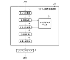
図1は、この発明の実施の形態1によるベクトル図形描画装置を示す構成図である。
図において、ベクトル図形描画装置100は、エッジ分割部1、交点算出部2、エッジデータリスト3、マスク生成部4、内外判定部5、塗潰し処理部6を備えている。
FIG. 1 is a block diagram showing a vector graphic drawing apparatus according to
In the figure, a vector
エッジ分割部1は、ベクトル図形の少なくとも頂点座標と描画色を含むベクトル図形のデータを入力し、その入力データが曲線であるか否かを判定して、曲線である場合には、微小な線分であるエッジに分割する手段である。即ち、エッジ分割部1は、電子データとして入力されたベクトル図形の輪郭データが曲線で入力された場合には、曲線を微小な線分に近似する。以後、この分割された線分のことをエッジと呼ぶ。
The
交点算出部2は、エッジ分割部1が生成したエッジとスキャンラインとの交点X座標をサブピクセル精度で求めてエッジデータをエッジデータリスト3に登録する手段である。即ち、交点算出部2は、算出した交点座標をエッジの向きの情報と合わせて、エッジデータリスト3に保存する。この時、エッジと走査線との交差回数をライトポインタに保存する。また、交点算出部2は、ベクトル図形の輪郭線の始点から開始して終点に達するまで同様の処理を繰り返し行う。
エッジデータリスト3は、交点算出部2が算出したベクトル図形の始点から終点までエッジデータのリストである。
The
The
マスク生成部4は、交点算出部2が算出したエッジデータをエッジデータリスト3から走査線(サブスキャンライン)単位で読み出し、図形のマスク情報を生成する手段であり、このマスク情報を生成するためのスキャンラインバッファ(以降、SLBと表記する)を有している。このSLBとは、各サブピクセル毎に、エッジとの交差回数(エッジの向きに基づいてインクリメント/デクリメントした合計値)の情報を有するものである。
The
内外判定部5は、マスク生成部4が生成したマスク情報を元に、図形の内外判定を行ってカバレッジ情報に変換する手段である。即ち、内外判定部5は、サブスキャンライン単位で1ピクセル分のカバレッジをカウントしたそれぞれのピクセルの値を保持するための1ライン分のカバレッジバッファ(以降、CVBと表記する)を備え、図形の内部と判定した場合は、このCVBを用いてカバレッジ(占有率)をカウントするよう構成されている。
塗潰し処理部6は、内外判定部5のカバレッジ情報に基づき、図形の内部と判定された領域に対して塗潰し処理を実行する手段である。
フレームバッファ7は、ベクトル図形描画装置100が生成したベクトル図形のピクセルデータを保持するものである。
The inside /
The
The
また、ベクトル図形描画装置100の構成要素であるエッジ分割部1、交点算出部2、マスク生成部4、内外判定部5及び塗潰し処理部6は、本発明の趣旨に従う図形描画プログラムをコンピュータに読み込ませてその動作を制御することにより、そのコンピュータ上でソフトウエアとハードウェアが協働した具体的な手段として実現することもできる。即ち、上記エッジ分割部1〜塗潰し処理部6の各構成は、それぞれの機能に対応したプログラムと、これらプログラムを実行するためのCPUやメモリといったハードウェアから実現することができる。
また、このコンピュータには、通信機能を有し、上記の図形描画プログラムを実行することができる携帯電話や携帯情報端末も含まれる。尚、コンピュータ自体の構成及びその基本的な機能については、当業者が当該技術分野の技術常識に基づいて容易に認識できるものであり、本発明の本質に直接関わるものでないので詳細な記載は省略する。
In addition, the
The computer also includes a mobile phone and a portable information terminal that have a communication function and can execute the graphic drawing program. It should be noted that the configuration of the computer itself and its basic functions can be easily recognized by those skilled in the art based on the common general technical knowledge in the technical field, and are not directly related to the essence of the present invention. To do.
次に、実施の形態1の動作について説明する。
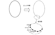
ベクトル図形描画装置100は、この図形描画装置100が搭載されたシステムのCPUから入力されたベクトル図形の情報として、頂点座標、曲線の制御点の座標、描画色等の情報が設定され、起動命令を受けることにより動作を開始する。起動命令を受けると、エッジ分割部1が起動し、輪郭線が曲線である場合には曲線を直線に近似してエッジ単位に分割する。例えば、図2に示すような図形内部の塗潰しを行う場合、エッジ分割部1は輪郭線を微小なエッジに分割する。描画開始位置の頂点座標をv(0)、i番目の頂点座標をv(i)、頂点数をnと表すと、エッジ分割部は、
v(0)v(1)、v(1)v(2)、v(2)v(3)、・・・、v(i)v(i+1)、・・・、v(n−1)v(0)
という順序でエッジを生成する。
Next, the operation of the first embodiment will be described.
In the vector
v (0) v (1), v (1) v (2), v (2) v (3), ..., v (i) v (i + 1), ..., v (n-1) v (0)
Edges are generated in this order.
尚、本発明のベクトル図形描画装置で描画するベクトル図形は、輪郭線が途中で交差してもよいが、必ず描画開始位置に戻ってくるような閉じた図形の集合であることが前提である。ここで、それぞれの閉じた図形のことをパスと呼ぶことにする。本発明のベクトル図形描画装置では、複数のパスの集合を1つの図形として扱うことも可能である。 The vector graphic drawn by the vector graphic drawing apparatus of the present invention is premised on a set of closed figures that always return to the drawing start position, although the contour lines may intersect in the middle. . Here, each closed figure is called a path. In the vector graphic drawing apparatus of the present invention, a set of a plurality of paths can be handled as one graphic.
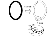
また、図3に示すように図2の図形の輪郭線をCPUから指定された線幅だけ太らせたような図形の描画方法の一例としては、図2の図形を中心として、内側と外側にそれぞれ線幅の2分の1の距離だけ離れた点の座標を算出し、図3の拡大図に示すように四角形を連続して描画する方法がある。この時、それぞれの四角形がパスに対応し、複数のパスをまとめたものが描画する図形となる。
図3では、描画開始位置の頂点座標をv(0)、i番目の頂点座標をv(i)、頂点数をnと表すと、エッジ分割部は、
v(0)v(1)、v(1)v(3)、v(3)v(2)、v(2)v(0)、
v(2)v(3)、v(3)v(5)、v(5)v(4)、v(4)v(2)・・・
という順序でエッジを生成する。尚、ここで示した順序は一つの例であり、更に輪郭線が滑らかに繋がるように、別の図形を挿入することも可能である。
以上で示したようにエッジ分割部1は、エッジの始点、終点の座標を交点算出部に対して随時出力する。この時、出力するエッジが図形の中間エッジ(0)であるか最終エッジ(1)であるかという判定フラグも一緒に出力する。
Further, as an example of a drawing method for drawing a figure in which the outline of the figure in FIG. 2 is thickened by the line width designated by the CPU as shown in FIG. 3, the figure in FIG. There is a method in which the coordinates of points separated by a distance of a half of the line width are calculated, and a rectangle is continuously drawn as shown in the enlarged view of FIG. At this time, each quadrangle corresponds to a path, and a combination of a plurality of paths is a figure to be drawn.
In FIG. 3, when the vertex coordinate of the drawing start position is represented by v (0), the i-th vertex coordinate is represented by v (i), and the number of vertices is represented by n,
v (0) v (1), v (1) v (3), v (3) v (2), v (2) v (0),
v (2) v (3), v (3) v (5), v (5) v (4), v (4) v (2)...
Edges are generated in this order. The order shown here is only an example, and it is possible to insert another figure so that the contour lines are connected smoothly.
As described above, the
交点算出部2は、エッジ分割部1から出力されたエッジと、スキャンラインとの交点座標を算出する。エッジの両端の座標をv0(x0,y0)、v1(x1,y1)、スキャンラインのY座標をyとする場合、スキャンラインとエッジとの交点X座標xs(y)は、以下の式(1)で求めることができる。ただし、(y0=y1)の時には、交点座標の算出は行わない。
xs(y)=x0+(x1−x0)/(y1−y0)×(y−y0)…(1)
The
xs (y) = x0 + (x1−x0) / (y1−y0) × (y−y0) (1)
ここで、本発明では、ベクトル図形の輪郭線部分のアンチエイリアス処理をサブピクセル分割法を利用して行う。サブピクセル分割法では、各ピクセルに対して、図形内部に含まれるサンプリング点の個数をカウントすることによりピクセル単位のカバレッジを算出する。 Here, in the present invention, the anti-aliasing processing of the contour portion of the vector graphic is performed using the sub-pixel division method. In the sub-pixel division method, the coverage in units of pixels is calculated by counting the number of sampling points included in the figure for each pixel.
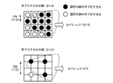
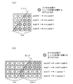
図4に4×4および2×2のサブピクセル分割の例を示す。
図4では、点線で示す図形を描画する場合に、図形内部に含まれるサブピクセルを黒丸、図形外部のサブピクセルを白丸で示している。1ピクセル当たりのサンプル数を多く取るほどカバレッジの精度が向上する。一般にsx×syのサブピクセル分割においてX方向のサブピクセル分割数(sx)と、Y方向のサブピクセル分割数(sy)の値が互いに異なっていてもよい。
従って、上式(1)においては、yの値をY方向のサンプル数(ysub)を考慮した値として、次の式(2)、(3)で表せる値とする。但し、iy0はエッジの最小Y座標の整数部、iy1はエッジの最大Y座標の整数部、nは整数とする。式(2)で表されるdyがY方向の刻み幅を表す。また、ysubの値は1以上の任意の整数値でよいが、2のべき乗で表される値とするのが望ましい。
dy=1/(2×ysub) …(2)
y=iy0+(2n+1)×dy …(3)
iy0≦y≦iy1 かつ min(y0,y1)≦y<max(y0,y1)…(4)
以降、式(3)で表すことのできる各Y座標のことをサブスキャンラインと呼ぶ。
FIG. 4 shows an example of 4 × 4 and 2 × 2 subpixel division.
In FIG. 4, when drawing a figure indicated by a dotted line, subpixels included in the figure are indicated by black circles, and subpixels outside the figure are indicated by white circles. As the number of samples per pixel is increased, the accuracy of coverage is improved. In general, in the subpixel division of sx × sy, the values of the subpixel division number (sx) in the X direction and the subpixel division number (sy) in the Y direction may be different from each other.
Therefore, in the above equation (1), the value of y is a value that can be expressed by the following equations (2) and (3), taking the number of samples (ysub) in the Y direction into consideration. However, iy0 is the integer part of the minimum Y coordinate of the edge, iy1 is the integer part of the maximum Y coordinate of the edge, and n is an integer. Dy represented by Formula (2) represents the step size in the Y direction. The ysub value may be an arbitrary integer value of 1 or more, but is preferably a value represented by a power of 2.
dy = 1 / (2 × ysub) (2)
y = iy0 + (2n + 1) × dy (3)
iy0 ≦ y ≦ iy1 and min (y0, y1) ≦ y <max (y0, y1) (4)
Hereinafter, each Y coordinate that can be expressed by Expression (3) is referred to as a sub-scan line.
交点算出部2は、yの値が式(4)の条件を満たす範囲内で式(1)〜(3)に従って、サブスキャンラインのY座標を2dyずつ変化させながら、エッジとの交点を順次求める。全ての交点座標の算出が終了した後、エッジ分割部1から出力された判定フラグの値が最終エッジ(1)である場合には、マスク生成部4を起動する。中間エッジ(0)である場合には、エッジ分割部1から次のエッジの座標と判定フラグを受け取り、同様の処理を繰り返す。
The
エッジデータリスト3は、交点算出部2が算出したサブスキャンラインとエッジとの交点情報を保存するためのリストである。本発明では、アンチエイリアス処理に対応するため、エッジデータリスト3のエッジデータを、エッジの向き、交点X座標の整数部、サンプル数の3つの情報で構成する。
The
エッジの向きは、イーブンオッド規則、ノンゼロ規則に対応するために必要となる。エッジの向きの定義は、エッジの両端のY座標を比較して(y0<y1)ならば上向き(UP)、(y0>y1)ならば下向き(DOWN)とする。交点X座標の整数部の値をエッジデータリスト3に保存し、小数点以下の情報は、サブピクセル分割の精度に応じて最低限必要な精度をサンプル数としてエッジデータリスト3に保存する。
The direction of the edge is necessary to cope with the even-odd rule and the non-zero rule. The definition of the direction of the edge is defined as upward (UP) if (y0 <y1) is compared with the Y coordinates of both ends of the edge, and downward (DOWN) if (y0> y1). The value of the integer part of the intersection X coordinate is stored in the
サンプル数とは、処理中のサブスキャンライン上において各ピクセル内部でエッジの右側にあるサンプル点の個数を表す。
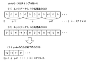
図5に4×4のサブピクセル分割の例を示す。図5(a)、(b)において、斜線付きの丸印で示したのがピクセル内部でエッジの右側に位置するサンプル点である。このようなサンプル点の個数を各サブスキャンライン(ysub0〜ysub3)でカウントする。サンプル点の中心がエッジ上にある場合には、エッジの右側にあるとして判定する。また、エッジが図5(b)に示すようにピクセルの境界をまたぐような場合には、サブスキャンライン単位で交点X座標の整数部の値が異なることになる。
The number of samples represents the number of sample points on the right side of the edge inside each pixel on the sub-scan line being processed.
FIG. 5 shows an example of 4 × 4 sub-pixel division. In FIGS. 5A and 5B, the sample points located on the right side of the edge inside the pixel are indicated by hatched circles. The number of such sample points is counted in each sub scan line (ysub0 to ysub3). If the center of the sample point is on the edge, it is determined that the sample point is on the right side of the edge. Further, when the edge crosses the boundary of the pixel as shown in FIG. 5B, the value of the integer part of the intersection X coordinate is different for each sub-scan line.
以上で示したエッジの向き、交点X座標の整数部、サンプル数の3つのデータを組として、エッジデータリスト3に登録する。
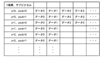
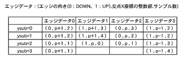
図6は、エッジデータリスト3のデータ構成を示す(Y方向のサブピクセル分割数=2の場合)。
各サブスキャンラインはY座標(y)と、サブピクセルカウンタ(ysub)の値によって決まる。各行のデータが当該サブスキャンラインとエッジとの交点座標の数に対応している。各データは、(エッジの向き(0:DOWN、1:UP),交点X座標の整数部,サンプル数)を2つずつ組にしたものである。2つのデータでエッジの向きは、どちらか一方がDOWN、もう一方がUPとなる。また1サブスキャンライン上に含まれるエッジデータは必ず偶数個となる。図6の方式は1つの例であり、他のデータ構成とすることも当然可能である。
The three pieces of data of the edge direction, the integer part of the intersection X coordinate, and the number of samples shown above are registered in the
FIG. 6 shows the data structure of the edge data list 3 (when the number of subpixel divisions in the Y direction = 2).
Each sub scan line is determined by the Y coordinate (y) and the value of the sub pixel counter (ysub). Each row of data corresponds to the number of intersection coordinates between the sub-scan line and the edge. Each data is a set of two (edge direction (0: DOWN, 1: UP), integer part of intersection X coordinate, number of samples). In the two data, one of the edge directions is DOWN and the other is UP. Also, the number of edge data included on one sub-scan line is always an even number. The system shown in FIG. 6 is an example, and other data configurations are naturally possible.
マスク生成部4は、交点算出部2からの起動命令を受けると、エッジデータリスト3に保存された交点情報を随時読み出し、アンチエイリアス処理のためのマスク情報を生成する。従来技術では、各サブスキャンライン上の交点座標を小さいものから順にソートする必要があったが、本発明の方式ではX座標のソートを必要としない。本発明では、1サブスキャンライン分の図形のマスク情報を格納できるSLBを利用し、1サブスキャンラインの処理が終わる度にこのバッファをクリアして繰り返し利用する。
When receiving the activation command from the
更に、ノンゼロ塗潰し規則にも対応するため、SLBの各アドレスに複数ビットを割り当てる。ビット数はエッジとスキャンラインとの交差回数に依存し、例えば、ビット数を8とした場合にはエッジとスキャンラインとの交差回数(エッジの向きに基づきインクリメントおよびデクリメントした合計値)が255の図形まで対応することができる。
従って、SLBのサイズは、最大で(フレームバッファ7のX方向サイズ×X方向サブピクセル数×ビット数)だけ必要である。
Furthermore, a plurality of bits are assigned to each address of the SLB in order to cope with the non-zero filling rule. The number of bits depends on the number of intersections between the edge and the scan line. It can handle up to figures.
Therefore, the maximum size of the SLB is required (the size of the
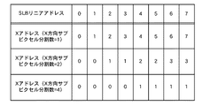
次に、SLBのリニアアドレスと、Xアドレスとの対応を図7に示す。Xアドレスは、X方向サンプル数(xsub)に応じて動的に変化させる。(xsub)が1の場合には、アンチエイリアス処理は無効となる。
SLBの0番地がX座標の0に対応するとすれば、図7においてSLBのi番地が以下のX座標に対応する。記号(>>)は右方向へのビットシフト演算子を表す。
例1. X方向サンプル数=1の場合、SLBのi番地がX座標iに対応する。
例2. X方向サンプル数=2の場合、SLBのi番地がX座標(i>>1)に対応する。
例3. X方向サンプル数=4の場合、SLBのi番地がX座標(i>>2)に対応する。
FIG. 7 shows the correspondence between the SLB linear address and the X address. The X address is dynamically changed according to the number of samples in the X direction (xsub). When (xsub) is 1, the antialiasing process is invalid.
If the
Example 1. When the number of samples in the X direction = 1, the SLB i address corresponds to the X coordinate i.
Example 2. When the number of samples in the X direction = 2, the i address of the SLB corresponds to the X coordinate (i >> 1).
Example 3 When the number of samples in the X direction = 4, the SLB i address corresponds to the X coordinate (i >> 2).
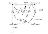
SLBのX座標の基準値は0としてもよいが、例えば、図8に示すベクトル図形の包含矩形の最小X座標(xmin)を基準値としてSLBの容量を節約することもできる。この時必要となるSLBのサイズは、(包含矩形の幅×X方向サブピクセル数×ビット数)だけ必要である。 Although the reference value of the X coordinate of the SLB may be 0, for example, the capacity of the SLB can be saved using the minimum X coordinate (xmin) of the inclusion rectangle of the vector graphic shown in FIG. 8 as a reference value. The size of the SLB required at this time is only (the width of the inclusion rectangle × the number of subpixels in the X direction × the number of bits).
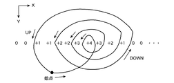
次に、SLBの状態の一例を図9を用いて説明する。図9(a)はSLBにおける値の一例を示している。また、このようなSLBの値となる図形としては例えば図10に示すような図形である。尚、図9の例ではX方向サブピクセル分割数(xsub)は2としている。 Next, an example of the state of the SLB will be described with reference to FIG. FIG. 9A shows an example of values in the SLB. Moreover, as a figure which becomes such an SLB value, for example, a figure as shown in FIG. In the example of FIG. 9, the number of sub-pixel divisions (xsub) in the X direction is 2.
図9(a)において、例えば、X座標(Xアドレス)が2の位置において、上向きのエッジとスキャンラインとが交差し、SLBの値は「+1」となる。尚、図10において、+1,+1,+2,…といった位置がサブピクセルの位置に相当している。次に、X座標が3の位置において、同様に、上向き(UP)のエッジとスキャンラインとが交差するため、SLBの値はインクリメントされ「+2」となる。そして、次のX座標が4の位置ではサブピクセル毎に上向きのエッジと交差するため、xsub=0のSLBの値が「+3」、xsub=1の値が「+4」となる。そして、次のX座標が5の位置のサブピクセルxsub=0では下向き(DOWN)のエッジと交差するためデクリメントされて「+3」となり、更にxsub=1でも下向きのエッジと交差することから「+2」となる。 In FIG. 9A, for example, at the position where the X coordinate (X address) is 2, the upward edge intersects with the scan line, and the value of SLB is “+1”. In FIG. 10, positions such as +1, +1, +2,... Correspond to subpixel positions. Next, at the position where the X coordinate is 3, similarly, since the upward (UP) edge and the scan line intersect, the value of the SLB is incremented to “+2”. Then, at the position where the next X coordinate is 4, each subpixel intersects with an upward edge, so that the SLB value of xsub = 0 is “+3” and the value of xsub = 1 is “+4”. Then, the sub-pixel xsub = 0 at the position where the next X coordinate is 5 intersects with the downward (DOWN) edge and is decremented to “+3”, and even when xsub = 1, it intersects with the downward edge. "
このように、X座標の増加する向きにスキャンラインを辿っていき、エッジと交差する度に、上向きエッジではSLBの値を+1とし、下向きエッジではその値を−1する。 In this way, the scan line is traced in the direction in which the X coordinate increases, and each time it intersects the edge, the SLB value is set to +1 for the upward edge, and the value is set to -1 for the downward edge.
内外判定部5は、SLBを随時読み出し、ピクセル単位のカバレッジ情報に変換する。内外判定方法は以下の通りとする。
(1)塗潰し規則がイーブンオッド規則の場合は、SLBの値が奇数の時に図形の内部であると判定する。
(2)塗潰し規則がノンゼロ規則の場合は、SLBの値が0以外であった時に図形の内部であると判定する。
このような規則に従って内外判定を行うと、例えば、図9および図10の図形では、図形の内部と判定される領域は、イーブンオッド規則では、+1と+3で示した領域であり、ノンゼロ規則では、+1,+2,+3,+4で示した領域となる。
The inside /
(1) When the painting rule is an even-odd rule, it is determined that the figure is inside the figure when the SLB value is an odd number.
(2) When the filling rule is a non-zero rule, it is determined that the figure is inside the figure when the SLB value is other than 0.
When the inside / outside determination is performed according to such a rule, for example, in the figures of FIG. 9 and FIG. 10, the area determined as the inside of the figure is an area indicated by +1 and +3 in the even-odd rule, and in the non-zero rule. , +1, +2, +3, +4.
本発明では、1スキャンライン分のピクセル単位のカバレッジ情報を格納できるCVBを利用する。CVBの各ピクセルのビット数は、サブピクセル分割数をカウントできるだけのビット数を確保する。例えば、2×2のサブピクセル分割の時は0〜4を表現するための3ビット、4×4のサブピクセル分割の時は0〜16表現するための5ビットが必要である。 The present invention uses CVB that can store pixel-by-pixel coverage information for one scan line. The number of bits of each pixel of the CVB secures the number of bits that can count the number of subpixel divisions. For example, 3 bits for expressing 0 to 4 are required for 2 × 2 subpixel division, and 5 bits for expressing 0 to 16 are required for 4 × 4 subpixel division.
内外判定部5は、1サブスキャンラインの処理が終わる度に図形の内部と判定された領域に対応するCVBの値をインクリメントする。また、1スキャンライン上に含まれるY方向サブピクセル分割数分のサブスキャンラインの処理が終わる度にCVBをクリアして繰り返し利用する。尚、CVBのXアドレスの基準値は0としてもよいが、ベクトル図形の包含矩形の最小X座標を基準値とすれば、CVBの容量を節約できる。
The inside /
次に、図9を参照し、SLBの情報から、内外判定を行う具体例について説明する。図9の例では、上述したように、X方向サブピクセル分割数(xsub)は2としており、このようなxsubの値を考慮して、SLBのサブピクセルxsub個分の情報を1ピクセルのカバレッジに変換する。例えば、SLBの値が(+2)および(+4)のサブピクセルは、イーブンオッド規則では図形の外部となるため、図9(b)に示すように、CVBの値はXアドレスが3では「0」、Xアドレスが4では一つのサブピクセルが奇数であるため、「+1」となる。また、ノンゼロ規則ではSLBの値がゼロ以外のサブピクセルは図形の内部となるため、図9(c)に示すように、CVBの値はXアドレス2からXアドレス5までが「+2」、Xアドレス6では、一方のサブピクセルのみがゼロ以外であるため、その値は「+1」となる。
Next, a specific example in which the inside / outside determination is performed from the SLB information will be described with reference to FIG. In the example of FIG. 9, as described above, the X-direction subpixel division number (xsub) is set to 2, and considering the value of such xsub, information for xsub subpixels of SLB is covered by one pixel. Convert to For example, since the subpixels having SLB values of (+2) and (+4) are outside the figure in the even-odd rule, the CVB value is “0” when the X address is 3, as shown in FIG. “When the X address is 4, one subpixel is an odd number, and therefore,“ +1 ”. In the non-zero rule, since the sub-pixels whose SLB value is not zero are inside the figure, the CVB value is “+2” from
塗潰し処理部6は、内外判定部5によって図形の内部と判定された領域内を塗潰すように順次ピクセルを生成する。ピクセルの描画色c(R、G、Bの各成分に対応)はCPUから設定された描画色をsrc、既にフレームバッファに書かれている色をdstとおくと、内外判定部5によって算出されたカバレッジの値(cv)を用いて以下の式(5)によって計算されるのが一例である。
c=src×cv+dst×(1−cv) …(5)
これにより、ベクトル図形の輪郭線にアンチエイリアス処理を施して描画することができる。
The filling
c = src * cv + dst * (1-cv) (5)
As a result, the outline of the vector figure can be drawn with anti-aliasing.
また、透過色を扱う場合には、一般的なアルファブレンド式を用いて、以下のように計算できる。但し、描画色のアルファ成分をsrca、アルファブレンド結果をbとおく。
b=src×srca+dst×(1−srca) …(6)
c=b×cv+dst×(1−cv) …(7)
また、ピクセル単位でカラー勾配を計算してグラデーション塗潰しを実現したり、テクスチャアドレスを計算してテクスチャ貼り付けを行ったりすることも可能である。
Further, in the case of handling a transparent color, it can be calculated as follows using a general alpha blend equation. However, the alpha component of the drawing color is srca, and the alpha blend result is b.
b = src * srca + dst * (1-srca) (6)
c = b * cv + dst * (1-cv) (7)
It is also possible to calculate a color gradient in units of pixels to realize gradation filling, or to calculate a texture address and apply a texture.
次に、実施の形態1によるベクトル図形描画処理の動作の詳細について説明する。
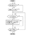
図11及び図12は、実施の形態1のベクトル図形描画装置によるベクトル図形描画処理の流れを示すフローチャートであり、以下、これらの図に沿って説明する。
先ず、エッジ分割部1は、図形の輪郭線が曲線であるか否かを判定する(ステップST1)。図形の輪郭線が曲線である場合には、微小線分(エッジ)に分割を行う(ステップST2)。輪郭線が直線である場合には、直線をそのままエッジとして扱う。
Next, the details of the operation of the vector graphic drawing process according to the first embodiment will be described.
FIG. 11 and FIG. 12 are flowcharts showing the flow of vector graphic drawing processing by the vector graphic drawing apparatus of the first embodiment, which will be described below with reference to these drawings.
First, the
次に、交点算出部2は、エッジとサブスキャンラインが交差するか否かを判定する(ステップST3)。判定結果がYESである場合には、サブスキャンラインとエッジとの交点座標を式(1)を用いて算出し、交点座標を算出後、前述したエッジの向き、交点X座標の整数部、サンプル数をエッジデータリスト3に保存する(ステップST4)。判定結果がNOである場合には、交点座標の算出とエッジデータの登録は行わない。
次に、処理しているエッジがベクトル図形の最終エッジであるかを判定し(ステップST5)、そうでない場合は上記のステップST3に戻って同様の処理を繰り返す。一方、ステップST5において、最終エッジである場合には、塗潰しを開始する。塗潰し開始後のフローチャートは図12に示すものである。
Next, the
Next, it is determined whether the edge being processed is the final edge of the vector graphic (step ST5). If not, the process returns to step ST3 and the same processing is repeated. On the other hand, if it is the last edge in step ST5, painting is started. The flowchart after the start of painting is shown in FIG.
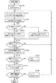
図12において、塗潰しが開始されると、マスク生成部4は、Y座標カウンタ(y)の初期値を図形の包含矩形の最小Y座標(ymin)に、Y方向サブピクセルカウンタ(ysub)を0に設定する(ステップST6)。次に、マスク生成部4は、エッジデータリスト3のY座標カウンタの値に対応するアドレスからエッジデータを1組読み出す(ステップST7)。上述したように1組のエッジデータは、一方がUPエッジの情報、もう一方がDOWNエッジの情報となっている。
In FIG. 12, when painting is started, the
続いて、以下の条件に従ってSLB判定フラグ(xflag)を生成する(ステップST8)。但し、読み出したi番目のエッジデータの整数X座標をそれぞれx(i)、x(i+1)として、これらの大小比較結果から以下の(A)、(B)の条件に従ってSLBを更新する範囲(xleft、xright)とSLB判定フラグを定める。 Subsequently, an SLB determination flag (xflag) is generated according to the following conditions (step ST8). However, the integer X coordinate of the read i-th edge data is set to x (i) and x (i + 1), respectively, and the SLB is updated from these magnitude comparison results according to the following conditions (A) and (B) ( xleft, xright) and an SLB determination flag.
(A)x(i)<x(i+1)の時
xleft=x(i)、xright=x(i+1)
i番目のエッジデータの向きがUPである場合、xflag=1
(B)x(i)≧x(i+1)の時
xleft=x(i+1)、xright=x(i)
i+1番目のエッジデータの向きがUPである場合、xflag=1
(A) When x (i) <x (i + 1) xleft = x (i), xright = x (i + 1)
When the direction of the i-th edge data is UP, xflag = 1
(B) When x (i) ≧ x (i + 1) xleft = x (i + 1), xright = x (i)
When the direction of the (i + 1) th edge data is UP, xflag = 1
マスク生成部4は、生成したSLB判定フラグの値を判定し(ステップST9)、SLB判定フラグが1である場合には、xleft≦x≦xrightの範囲のSLBをインクリメントする(ステップST10)。一方、SLB判定フラグが0である場合には、xleft≦x≦xrightの範囲のSLBをデクリメントする(ステップST11)。
但し、x=xleftの位置においては、サンプル点がエッジの右側にあるサブピクセルに対応するSLBだけインクリメントする。x=xrightの位置においては、サンプル点がエッジの左側にあるサブピクセルの位置に対応するSLBのみをインクリメントする。
次に、マスク生成部4は、最終エッジデータかを判定し(ステップST12)、最終エッジデータでなかった場合はステップST7に戻って、これらの処理を繰り返し、最終エッジデータであった場合は、内外判定部5を起動し、ステップST13に移行する。
The
However, at the position of x = xleft, the sample point is incremented by SLB corresponding to the sub-pixel on the right side of the edge. At the position of x = xright, only the SLB corresponding to the position of the subpixel whose sample point is on the left side of the edge is incremented.
Next, the
ステップST13において、内外判定部5は、処理中のサブスキャンライン上におけるSLBの情報を読み出し、前述した内外判定規則に従って、ピクセル単位のカバレッジに変換する。次に、処理中のサブスキャンラインが最終サブスキャンラインである、即ち、Y方向サブピクセルカウンタが(ysub=(Y方向サンプル数−1))の条件を満たすか否かを判定する(ステップST14)。最終サブスキャンラインでない場合は、Y方向サブピクセルカウンタ(ysub)をインクリメントした後(ステップST15)、ステップST7に戻ってこれ以降の処理を繰り返す。一方、ステップST14において、最終サブスキャンラインであった場合には、スキャンラインy上のピクセル生成を開始する(ステップST16)。
In step ST13, the inside /
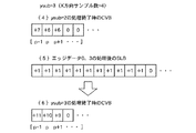
図13〜図16に4×4のサブピクセル分割時の図形描画例を示す。
図13は、1スキャンライン上の3ピクセル分をサブピクセル単位で表したものである。また、図14はスキャンライン上のエッジデータを示す図である。1スキャンラインは4つのサブスキャンラインで構成される。ysub=0〜2のサブスキャンラインは、エッジとの交差回数がそれぞれ4回であり、ysub=3のサブスキャンラインは、エッジとの交差回数が2回である。マスク生成部4及び内外判定部5は、図14に示すエッジデータを元に、図13に黒丸で示しているサブピクセルが図形の内部に含まれるようにするため、以下の手順に従って判定を行う。
FIG. 13 to FIG. 16 show examples of graphic drawing when 4 × 4 sub-pixels are divided.
FIG. 13 shows three pixels on one scan line in sub-pixel units. FIG. 14 is a diagram showing edge data on a scan line. One scan line is composed of four sub-scan lines. The sub scan lines with ysub = 0 to 2 each have four times of intersections with the edges, and the sub scan lines with ysub = 3 have two times of intersections with the edges. Based on the edge data shown in FIG. 14, the
図15は、ysub=0のサブスキャンラインの処理手順を例として示す説明図であり、図中の(1)〜(3)の状態が以下の(1)〜(3)の説明に対応している。
(1)マスク生成部4は、図14のysub=0に対応するアドレスからエッジデータ0、1を読み出した結果、前記判定条件(B)により
xleft=xright=p+1、xflag=1となるので
x=p+1の範囲のSLBをインクリメントする。
FIG. 15 is an explanatory diagram illustrating, as an example, a processing procedure for a sub scan line with ysub = 0, and states (1) to (3) in the drawing correspond to the following descriptions (1) to (3). ing.
(1) Since the
(2)図14のysub=0に対応するアドレスからエッジデータ2、3を読み出した結果、前記判定条件(B)により
xleft=p−1、xright=p、xflag=1となるので
p−1≦x≦pの範囲のSLBをインクリメントする。
(2) As a result of reading the
(3)ysub=0のサブスキャンライン上では、エッジデータ2、3の組が最終なのでSLBへのマスク生成を終了し、内外判定部5は、4サブピクセル分の内外判定結果を1ピクセル分のカバレッジ情報として変換し、CVBをインクリメントする(ysub=0であるから、CVBは0クリアされている)。その後、SLBをクリアし、ysub=1のサブスキャンラインを同様に処理する。
(3) Since the set of
そして、ysub=1、ysub=2のサブスキャンラインに対しても同様の処理を行った後、ysub=3の最終サブスキャンラインの処理を開始する。 Then, after the same processing is performed for the sub-scan line of ysub = 1 and ysub = 2, the processing of the final sub-scan line of ysub = 3 is started.
図16は、ysub=3のサブスキャンラインの処理手順を例として示す説明図であり、図中の(4)〜(6)の状態は以下の(4)〜(6)の説明に対応している。
(4)ysub=2のサブスキャンラインの処理が終了した時点でCVBは図16の(4)に示す状態になっている。
FIG. 16 is an explanatory diagram illustrating, as an example, the processing procedure of the sub scan line with ysub = 3. The states (4) to (6) in the drawing correspond to the following descriptions (4) to (6). ing.
(4) The CVB is in the state shown in (4) of FIG. 16 when the processing of the sub scan line with ysub = 2 is completed.
(5)次いで、マスク生成部4は、図14のysub=3に対応するアドレスからエッジデータ0と3を読み出した結果、前記判定条件(B)により
xleft=p−1、xright=p+1、xflag=1となるので
p−1≦x≦p+1の範囲のSLBをインクリメントする。
(5) Next, as a result of reading the
(6)ysub=3のサブスキャンライン上では、エッジデータ0、3の組が最終なのでSLBへのマスク生成を終了し、内外判定部5は、4サブピクセル分の内外判定結果を1ピクセル分のカバレッジ情報として変換し、CVBをインクリメントする。最終サブスキャンラインであるから、CVBのアドレスをX座標、CVBに保存されている値をカバレッジ、Y座標カウンタの値をY座標として、1スキャンライン分のピクセルデータ生成を開始する。カバレッジが0のピクセルは描画する必要がない。
(6) On the sub scan line with ysub = 3, since the set of
図12に戻り、ピクセル生成が開始されると、塗潰し処理部6は、内外判定部5で図形の内部と判定された領域に含まれるピクセルを順次生成して塗潰し処理を行う(ステップST16)。その後、1スキャンライン上で図形の内部に含まれる全てのピクセルの塗潰し処理が終了すると、Y座標が最終値(ymax)であるか否かの判定を行う(ステップST17)。Y座標が最終値でない場合には、Y座標カウンタyのインクリメント、Y方向サブピクセルカウンタ(ysub)のリセットを行った後(ステップST18)、ステップST7に戻り、これ以降の処理を繰り返す。ステップST17において、Y座標が最終値(ymax)である場合には、ベクトル図形の描画を終了する。
Returning to FIG. 12, when the pixel generation is started, the filling
以上のように、この実施の形態1のベクトル図形描画装置によれば、ベクトル図形の少なくとも頂点座標を含むベクトル図形のデータを入力し、入力データが曲線である場合には、この曲線を微小な線分であるエッジに分割するエッジ分割部と、エッジ分割部が生成したエッジとスキャンラインとの交点座標をサブピクセル精度で求めた値をエッジデータとして算出する交点算出部と、算出されたエッジデータをサブスキャンライン単位で取得し、図形のマスク情報を生成するマスク生成部と、マスク生成部が生成したマスク情報を元に、図形の内外判定を行ってカバレッジ情報に変換する内外判定部と、内外判定部のカバレッジ情報に基づき、前記図形の内部と判定された領域に対して塗潰し処理を実行する塗潰し処理部とを備えたので、ベクトル図形描画装置として多大な計算量を要することなく高速な描画を実行することができる。 As described above, according to the vector graphic drawing apparatus of the first embodiment, when the vector graphic data including at least the vertex coordinates of the vector graphic is input and the input data is a curve, the curve is made minute. An edge dividing unit that divides the image into edges that are line segments; an intersection calculating unit that calculates, as edge data, a value obtained by subpixel accuracy of the intersection coordinates between the edge and the scan line generated by the edge dividing unit; and the calculated edge A mask generation unit that obtains data in units of sub-scan lines and generates mask information of the figure, and an inside / outside determination unit that performs inside / outside determination of the figure based on the mask information generated by the mask generation unit and converts it into coverage information; Since, based on the coverage information of the inside / outside determination unit, with a painting processing unit that performs a painting process on the area determined to be the inside of the figure, Vector capable of performing fast rendering without requiring a great deal of computational as graphics drawing apparatus.
また、実施の形態1のベクトル図形描画装置によれば、交点算出部は、交点座標の算出時にピクセル内部におけるエッジとサンプル点との位置関係を判定し、この判定結果と交点座標の整数部およびエッジの向きの情報をエッジデータとして算出するようにしたので、アンチエイリアス処理を実現する際に、多大な計算量を要することなく高速な描画を実行することができる。 Further, according to the vector graphic drawing apparatus of the first embodiment, the intersection calculation unit determines the positional relationship between the edge and the sample point in the pixel when calculating the intersection coordinates, and the determination result and the integer part of the intersection coordinates and Since edge direction information is calculated as edge data, high-speed rendering can be executed without requiring a large amount of calculation when realizing anti-aliasing processing.
また、実施の形態1のベクトル図形描画装置によれば、マスク生成部は、サブピクセル毎に、エッジの向きに基づいたスキャンラインとの交差回数を保持する1ライン分のスキャンラインバッファを備えたので、イーブンオッド規則やノンゼロ規則といった塗潰し規則に対応することができる。 Further, according to the vector graphic drawing apparatus of the first embodiment, the mask generation unit includes a scan line buffer for one line that holds the number of intersections with the scan line based on the edge direction for each subpixel. Therefore, it is possible to cope with a painting rule such as an even-odd rule or a non-zero rule.
また、実施の形態1のベクトル図形描画装置によれば、内外判定部は、サブスキャンライン単位で1ピクセル分のカバレッジをカウントしたそれぞれのピクセルの値を保持するための1ライン分のカバレッジバッファを備え、このカバレッジバッファを用いてカバレッジ情報を保持するようにしたので、アンチエイリアス処理を施した任意のベクトル図形を塗潰し規則(イーブンオッド規則、ノンゼロ規則)を考慮した上で、それぞれ1ライン分のスキャンラインバッファ及びカバレッジバッファを繰り返し利用することにより、単純な処理で高速に描画することができる。 In addition, according to the vector graphic drawing apparatus of the first embodiment, the inside / outside determination unit has a coverage buffer for one line for holding the value of each pixel obtained by counting the coverage for one pixel in units of sub-scan lines. Since this coverage buffer is used to hold coverage information, each vector figure subjected to anti-aliasing processing is filled with one line after taking into account the rules (even-odd rule, non-zero rule). By repeatedly using the scan line buffer and the coverage buffer, it is possible to draw at high speed with simple processing.
また、実施の形態1のベクトル図形描画装置のプログラムによれば、コンピュータを上記いずれかのベクトル描画装置として機能させるようにしたので、多大な計算量を要することなく高速な描画を実行することができるベクトル図形描画装置をコンピュータ上に実現することができる。
また、実施の形態1のベクトル図形描画装置によれば、ベクトル図形描画装置のハードウェア化を行う場合でも回路規模を最小限に抑えることができる。
更に、スキャンラインとエッジとの交差回数が多い図形を扱ったり、アンチエイリアス処理のサンプル数を変化させたりする場合でも、エッジデータリストの構成およびスキャンラインバッファのアドレス割り当てを変えることによって柔軟に対応することが可能である。
Further, according to the program of the vector graphic drawing apparatus of the first embodiment, since the computer is caused to function as one of the vector drawing apparatuses described above, high-speed drawing can be executed without requiring a large amount of calculation. A vector graphic drawing device capable of being realized can be realized on a computer.
Further, according to the vector graphic drawing apparatus of the first embodiment, the circuit scale can be minimized even when the vector graphic drawing apparatus is implemented as hardware.
Furthermore, even when dealing with figures that have a large number of intersections between scan lines and edges, or when changing the number of antialiasing samples, it is possible to flexibly cope with changes in the configuration of the edge data list and the address assignment of the scan line buffer. It is possible.
実施の形態2.
上記実施の形態1では、図形に含まれるエッジ分割部1が生成したエッジとスキャンラインとの交点座標を全てエッジデータリスト3に保存してからベクトル図形の塗潰しを開始していたが、エッジとスキャンラインとの交点座標の算出を1スキャンライン分行う度に1スキャンライン分の塗潰しを行い、同様の処理をベクトル図形の包含矩形のY方向サイズ分だけ繰り返すようにしてもよく、これを実施の形態2として以下説明する。
In the first embodiment, the filling of the vector graphic is started after all the intersection coordinates of the edge and the scan line generated by the
図面上の構成は実施の形態1と同様であるため、図1を援用して説明する。
実施の形態2の交点算出部2は、エッジ分割部1が生成したエッジとスキャンラインとの交点X座標をサブピクセル精度で求めた値をエッジデータとして算出してエッジデータリスト3に登録し、また、マスク生成部4は、エッジデータリスト3に登録されているエッジデータをサブスキャンライン単位で取得し、図形のマスク情報を生成するよう構成されている。また、内外判定部5及び塗潰し処理部6は、1スキャンライン分の値が得られる度に処理を行うようになっている。
Since the configuration on the drawing is the same as that of the first embodiment, description will be made with reference to FIG.
The
次に、実施の形態2の動作について説明する。
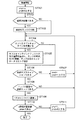
図17は、実施の形態2によるベクトル図形描画処理の塗潰し開始までの流れを示すフローチャートである。
最初にY座標カウンタを最小Y座標、Y方向サブピクセルカウンタysubを0に設定する(ステップST101)。エッジ分割部1は、図形の輪郭線が曲線であるか否かを判定する(ステップST102)。図形の輪郭線が曲線である場合には、微小線分(エッジ)に分割を行う(ステップST103)。輪郭線が直線である場合には、直線をそのままエッジとして扱う。
Next, the operation of the second embodiment will be described.
FIG. 17 is a flowchart showing a flow until the start of painting in the vector graphic drawing process according to the second embodiment.
First, the Y coordinate counter is set to the minimum Y coordinate, and the Y direction subpixel counter ysub is set to 0 (step ST101). The
次に、交点算出部2は、入力されたエッジがY座標カウンタの値に対応するサブスキャンラインと交差するか否かを判定する(ステップST104)。判定結果がYESである場合、交点算出部2は、実施の形態1で説明した式(1)〜(3)に従って、Y座標カウンタの値に対応するサブスキャンラインとエッジとの交点座標を算出し、実施の形態1と同様に、エッジの向き、交点X座標の整数部、サンプル数をエッジデータリスト3に保存する(ステップST105)。判定結果がNOである場合、交点X座標の算出およびエッジデータリスト3へのエッジデータの登録は行わない。
Next, the
次に、処理中のサブスキャンラインが最終サブスキャンラインである、即ち、Y方向サブピクセルカウンタが(ysub=(Y方向サンプル数−1))の条件を満たすか否かを判定する(ステップST106)。最終サブスキャンラインでない場合は、Y方向サブピクセルカウンタ(ysub)をインクリメントした後(ステップST107)、ステップST104に戻り、ステップST104以降の処理を繰り返す。 Next, it is determined whether or not the sub-scan line being processed is the last sub-scan line, that is, the Y-direction sub-pixel counter satisfies the condition (ysub = (number of samples in Y-direction−1)) (step ST106). ). If it is not the final sub-scan line, the Y-direction sub-pixel counter (ysub) is incremented (step ST107), then the process returns to step ST104, and the processes after step ST104 are repeated.
ステップST106において、最終サブスキャンラインである場合には、処理中のエッジが図形の最終エッジであるか否かを判定する(ステップST108)。ここでの判定結果がNOである場合は次のエッジに対してステップST104以下の処理を繰り返す。判定結果がYESである場合には、1スキャンライン分の塗潰しを開始する(ステップST109)。1スキャンライン分の塗潰し手順は、実施の形態1における図12においてymin、ymaxに対して現在処理中のスキャンラインY座標の値を代入したものと等しい。図12のステップST17に達すると、必ず1スキャンライン分の塗潰しが終了する。 If it is the last sub-scan line in step ST106, it is determined whether or not the edge being processed is the last edge of the figure (step ST108). If the determination result here is NO, the processing from step ST104 onward is repeated for the next edge. If the determination result is YES, painting for one scan line is started (step ST109). The painting procedure for one scan line is equivalent to substituting the value of the scan line Y coordinate currently being processed for ymin and ymax in FIG. 12 in the first embodiment. When step ST17 in FIG. 12 is reached, painting for one scan line is always completed.
1スキャンライン分の塗潰しが終了すると、Y座標が最終値(ymax)であるか否かの判定を行う(ステップST110)。Y座標が最終値でない場合には、Y座標カウンタ(y)のインクリメント、Y方向サブピクセルカウンタ(ysub)のリセットを行った後(ステップST111)、ステップST104以下の処理を繰り返す。Y座標が最終値(ymax)である場合には、ベクトル図形の描画を終了する。 When painting of one scan line is completed, it is determined whether or not the Y coordinate is the final value (ymax) (step ST110). If the Y coordinate is not the final value, the Y coordinate counter (y) is incremented and the Y-direction subpixel counter (ysub) is reset (step ST111), and then the processing from step ST104 onward is repeated. When the Y coordinate is the final value (ymax), the drawing of the vector graphic is finished.
以上のように、実施の形態2のベクトル図形描画装置によれば、エッジとスキャンラインとの交点座標の算出を1スキャンライン分行う度に1スキャンライン分の塗潰しを行い、同様の処理をベクトル図形の包含矩形のY方向サイズ分だけ繰り返すようにしたので、エッジデータリストの使用領域を節約することができ、ベクトル図形描画装置としての回路規模を更に抑えることができる。 As described above, according to the vector graphic drawing apparatus of the second embodiment, every time the calculation of the intersection coordinates of the edge and the scan line is performed for one scan line, the same processing is performed for one scan line. Since it is repeated by the size in the Y direction of the inclusion rectangle of the vector graphic, the area used in the edge data list can be saved, and the circuit scale as the vector graphic drawing apparatus can be further suppressed.
1 エッジ分割部、2 交点算出部、3 エッジデータリスト、4 マスク生成部、5 内外判定部、6 塗潰し処理部、100 ベクトル図形描画装置。
DESCRIPTION OF
Claims (5)
前記エッジ分割部が生成したエッジとスキャンラインとの交点座標をサブピクセル精度で求めた値をエッジデータとして算出する交点算出部と、
前記算出されたエッジデータをサブスキャンライン単位で取得し、図形のマスク情報を生成するマスク生成部と、
前記マスク生成部が生成したマスク情報を元に、図形の内外判定を行ってカバレッジ情報に変換する内外判定部と、
前記内外判定部のカバレッジ情報に基づき、前記図形の内部と判定された領域に対して塗潰し処理を実行する塗潰し処理部とを備えたベクトル図形描画装置。 When data of a vector graphic including at least vertex coordinates of the vector graphic is input and the input data is a curve, an edge dividing unit that divides the curve into edges that are minute line segments;
An intersection calculation unit that calculates, as edge data, a value obtained by subpixel accuracy of an intersection coordinate between the edge and the scan line generated by the edge dividing unit;
A mask generation unit that acquires the calculated edge data in units of sub-scan lines and generates mask information of a figure;
Based on the mask information generated by the mask generation unit, an inside / outside determination unit that performs inside / outside determination of a figure and converts it into coverage information;
A vector graphic drawing apparatus comprising: a painting processing unit that performs a painting process on an area determined to be inside the graphic based on coverage information of the inside / outside judgment unit.
Priority Applications (1)
| Application Number | Priority Date | Filing Date | Title |
|---|---|---|---|
| JP2006181921A JP4772604B2 (en) | 2006-06-30 | 2006-06-30 | Vector graphic drawing apparatus and program thereof |
Applications Claiming Priority (1)
| Application Number | Priority Date | Filing Date | Title |
|---|---|---|---|
| JP2006181921A JP4772604B2 (en) | 2006-06-30 | 2006-06-30 | Vector graphic drawing apparatus and program thereof |
Publications (2)
| Publication Number | Publication Date |
|---|---|
| JP2008009897A true JP2008009897A (en) | 2008-01-17 |
| JP4772604B2 JP4772604B2 (en) | 2011-09-14 |
Family
ID=39068013
Family Applications (1)
| Application Number | Title | Priority Date | Filing Date |
|---|---|---|---|
| JP2006181921A Active JP4772604B2 (en) | 2006-06-30 | 2006-06-30 | Vector graphic drawing apparatus and program thereof |
Country Status (1)
| Country | Link |
|---|---|
| JP (1) | JP4772604B2 (en) |
Cited By (4)
| Publication number | Priority date | Publication date | Assignee | Title |
|---|---|---|---|---|
| JP2010055380A (en) * | 2008-08-28 | 2010-03-11 | Sharp Corp | Data creation device, data creation method, program for data creation, drawing device, drawing method, program for drawing, and computer readable recording medium |
| JP2010136192A (en) * | 2008-12-05 | 2010-06-17 | Canon Inc | Image processor, image processing method, and computer program |
| WO2010134124A1 (en) * | 2009-05-19 | 2010-11-25 | 三菱電機株式会社 | Vector graphic drawing device |
| US11942305B2 (en) | 2021-08-10 | 2024-03-26 | Nuflare Technology, Inc. | Data generation method, charged particle beam irradiation device, and computer-readable recording medium |
Citations (9)
| Publication number | Priority date | Publication date | Assignee | Title |
|---|---|---|---|---|
| JPH0668271A (en) * | 1992-08-17 | 1994-03-11 | Ricoh Co Ltd | Image processor |
| JPH06314091A (en) * | 1993-04-28 | 1994-11-08 | Fujitsu Ltd | Outline filling method and its circuit |
| JPH09102048A (en) * | 1995-10-03 | 1997-04-15 | Matsushita Electric Ind Co Ltd | Image processing device |
| JPH10143676A (en) * | 1996-11-15 | 1998-05-29 | Fuji Xerox Co Ltd | Picture processor and method for processing the same and recording medium |
| JPH1173516A (en) * | 1997-08-27 | 1999-03-16 | Fuji Xerox Co Ltd | Image processor |
| JP2000149036A (en) * | 1998-09-09 | 2000-05-30 | Fuji Xerox Co Ltd | Graphic data processor |
| JP2001052190A (en) * | 1993-06-01 | 2001-02-23 | Ductus Inc | Raster form synthesizing method for direct multilevel filling |
| JP2001067487A (en) * | 1999-08-25 | 2001-03-16 | Fuji Xerox Co Ltd | Drawing processor |
| JP2002334341A (en) * | 2001-05-11 | 2002-11-22 | Fuji Xerox Co Ltd | Image processor |
-
2006
- 2006-06-30 JP JP2006181921A patent/JP4772604B2/en active Active
Patent Citations (9)
| Publication number | Priority date | Publication date | Assignee | Title |
|---|---|---|---|---|
| JPH0668271A (en) * | 1992-08-17 | 1994-03-11 | Ricoh Co Ltd | Image processor |
| JPH06314091A (en) * | 1993-04-28 | 1994-11-08 | Fujitsu Ltd | Outline filling method and its circuit |
| JP2001052190A (en) * | 1993-06-01 | 2001-02-23 | Ductus Inc | Raster form synthesizing method for direct multilevel filling |
| JPH09102048A (en) * | 1995-10-03 | 1997-04-15 | Matsushita Electric Ind Co Ltd | Image processing device |
| JPH10143676A (en) * | 1996-11-15 | 1998-05-29 | Fuji Xerox Co Ltd | Picture processor and method for processing the same and recording medium |
| JPH1173516A (en) * | 1997-08-27 | 1999-03-16 | Fuji Xerox Co Ltd | Image processor |
| JP2000149036A (en) * | 1998-09-09 | 2000-05-30 | Fuji Xerox Co Ltd | Graphic data processor |
| JP2001067487A (en) * | 1999-08-25 | 2001-03-16 | Fuji Xerox Co Ltd | Drawing processor |
| JP2002334341A (en) * | 2001-05-11 | 2002-11-22 | Fuji Xerox Co Ltd | Image processor |
Cited By (6)
| Publication number | Priority date | Publication date | Assignee | Title |
|---|---|---|---|---|
| JP2010055380A (en) * | 2008-08-28 | 2010-03-11 | Sharp Corp | Data creation device, data creation method, program for data creation, drawing device, drawing method, program for drawing, and computer readable recording medium |
| JP2010136192A (en) * | 2008-12-05 | 2010-06-17 | Canon Inc | Image processor, image processing method, and computer program |
| US8295602B2 (en) | 2008-12-05 | 2012-10-23 | Canon Kabushiki Kaisha | Image processing apparatus and image processing method |
| WO2010134124A1 (en) * | 2009-05-19 | 2010-11-25 | 三菱電機株式会社 | Vector graphic drawing device |
| JP5159949B2 (en) * | 2009-05-19 | 2013-03-13 | 三菱電機株式会社 | Vector drawing equipment |
| US11942305B2 (en) | 2021-08-10 | 2024-03-26 | Nuflare Technology, Inc. | Data generation method, charged particle beam irradiation device, and computer-readable recording medium |
Also Published As
| Publication number | Publication date |
|---|---|
| JP4772604B2 (en) | 2011-09-14 |
Similar Documents
| Publication | Publication Date | Title |
|---|---|---|
| JP4693660B2 (en) | Drawing apparatus, drawing method, and drawing program | |
| CN104520901B (en) | Method and device for path reproduction | |
| US8928667B2 (en) | Rendering stroked curves in graphics processing systems | |
| US8928668B2 (en) | Method and apparatus for rendering a stroked curve for display in a graphics processing system | |
| KR20050030595A (en) | Image processing apparatus and method | |
| JPH07210697A (en) | Method and apparatus for generating sub-pixel mask in computer graphic system | |
| US20090309898A1 (en) | Rendering apparatus and method | |
| WO2009090726A1 (en) | Graphic drawing device and graphic drawing method | |
| US20200279415A1 (en) | Efficiently Computed Distance Fields | |
| CN101714259B (en) | Graphics processing systems | |
| JP3332165B2 (en) | Image processing device | |
| JP2005100176A (en) | Image processing apparatus and method | |
| EP0231060B1 (en) | Fixed character string clipping in a graphics display system | |
| EP1958162B1 (en) | Vector graphics anti-aliasing | |
| JP5172640B2 (en) | Vector drawing equipment | |
| JP2007304871A (en) | Drawing apparatus, drawing method, and drawing program | |
| JP4772604B2 (en) | Vector graphic drawing apparatus and program thereof | |
| JP5777726B2 (en) | Drawing apparatus and drawing program | |
| JPH08293021A (en) | Image coordinate conversion method | |
| US11776179B2 (en) | Rendering scalable multicolored vector content | |
| JP3009525B2 (en) | Vector image drawing equipment | |
| JP5159949B2 (en) | Vector drawing equipment | |
| US6504543B1 (en) | Polygon drawing method and polygon drawing apparatus | |
| JP2008299642A (en) | Graphic drawing device | |
| US6515661B1 (en) | Anti-aliasing buffer |
Legal Events
| Date | Code | Title | Description |
|---|---|---|---|
| RD04 | Notification of resignation of power of attorney |
Free format text: JAPANESE INTERMEDIATE CODE: A7424 Effective date: 20080701 |
|
| A621 | Written request for application examination |
Free format text: JAPANESE INTERMEDIATE CODE: A621 Effective date: 20090415 |
|
| A131 | Notification of reasons for refusal |
Free format text: JAPANESE INTERMEDIATE CODE: A131 Effective date: 20110322 |
|
| A521 | Request for written amendment filed |
Free format text: JAPANESE INTERMEDIATE CODE: A523 Effective date: 20110517 |
|
| TRDD | Decision of grant or rejection written | ||
| A01 | Written decision to grant a patent or to grant a registration (utility model) |
Free format text: JAPANESE INTERMEDIATE CODE: A01 Effective date: 20110614 |
|
| A01 | Written decision to grant a patent or to grant a registration (utility model) |
Free format text: JAPANESE INTERMEDIATE CODE: A01 |
|
| A61 | First payment of annual fees (during grant procedure) |
Free format text: JAPANESE INTERMEDIATE CODE: A61 Effective date: 20110622 |
|
| FPAY | Renewal fee payment (event date is renewal date of database) |
Free format text: PAYMENT UNTIL: 20140701 Year of fee payment: 3 |
|
| R150 | Certificate of patent or registration of utility model |
Free format text: JAPANESE INTERMEDIATE CODE: R150 Ref document number: 4772604 Country of ref document: JP Free format text: JAPANESE INTERMEDIATE CODE: R150 |
|
| R250 | Receipt of annual fees |
Free format text: JAPANESE INTERMEDIATE CODE: R250 |
|
| R250 | Receipt of annual fees |
Free format text: JAPANESE INTERMEDIATE CODE: R250 |
|
| R250 | Receipt of annual fees |
Free format text: JAPANESE INTERMEDIATE CODE: R250 |
|
| R250 | Receipt of annual fees |
Free format text: JAPANESE INTERMEDIATE CODE: R250 |
|
| R250 | Receipt of annual fees |
Free format text: JAPANESE INTERMEDIATE CODE: R250 |
|
| R250 | Receipt of annual fees |
Free format text: JAPANESE INTERMEDIATE CODE: R250 |
|
| R250 | Receipt of annual fees |
Free format text: JAPANESE INTERMEDIATE CODE: R250 |
|
| R250 | Receipt of annual fees |
Free format text: JAPANESE INTERMEDIATE CODE: R250 |
|
| R250 | Receipt of annual fees |
Free format text: JAPANESE INTERMEDIATE CODE: R250 |
|
| R250 | Receipt of annual fees |
Free format text: JAPANESE INTERMEDIATE CODE: R250 |
|
| R250 | Receipt of annual fees |
Free format text: JAPANESE INTERMEDIATE CODE: R250 |