JP2008009848A - Small-scale diagnostic system - Google Patents
Small-scale diagnostic system Download PDFInfo
- Publication number
- JP2008009848A JP2008009848A JP2006181329A JP2006181329A JP2008009848A JP 2008009848 A JP2008009848 A JP 2008009848A JP 2006181329 A JP2006181329 A JP 2006181329A JP 2006181329 A JP2006181329 A JP 2006181329A JP 2008009848 A JP2008009848 A JP 2008009848A
- Authority
- JP
- Japan
- Prior art keywords
- information
- patient
- input
- image
- screen
- Prior art date
- Legal status (The legal status is an assumption and is not a legal conclusion. Google has not performed a legal analysis and makes no representation as to the accuracy of the status listed.)
- Pending
Links
- 230000004044 response Effects 0.000 claims abstract description 5
- 238000003384 imaging method Methods 0.000 claims description 70
- 238000003745 diagnosis Methods 0.000 claims description 44
- 230000005540 biological transmission Effects 0.000 claims description 7
- 230000006870 function Effects 0.000 description 49
- 238000012545 processing Methods 0.000 description 37
- 238000003860 storage Methods 0.000 description 32
- 238000004891 communication Methods 0.000 description 21
- 238000006243 chemical reaction Methods 0.000 description 20
- 238000012790 confirmation Methods 0.000 description 15
- 238000000034 method Methods 0.000 description 15
- 230000005855 radiation Effects 0.000 description 15
- 238000004364 calculation method Methods 0.000 description 8
- 239000003814 drug Substances 0.000 description 7
- 208000027418 Wounds and injury Diseases 0.000 description 6
- 229940079593 drug Drugs 0.000 description 5
- 239000000284 extract Substances 0.000 description 5
- 238000007689 inspection Methods 0.000 description 5
- 230000003287 optical effect Effects 0.000 description 5
- 239000000523 sample Substances 0.000 description 5
- OAICVXFJPJFONN-UHFFFAOYSA-N Phosphorus Chemical compound [P] OAICVXFJPJFONN-UHFFFAOYSA-N 0.000 description 4
- 239000002872 contrast media Substances 0.000 description 4
- 206010052428 Wound Diseases 0.000 description 3
- 230000006378 damage Effects 0.000 description 3
- 230000000694 effects Effects 0.000 description 3
- 238000000605 extraction Methods 0.000 description 3
- 208000014674 injury Diseases 0.000 description 3
- 238000004458 analytical method Methods 0.000 description 2
- 238000013500 data storage Methods 0.000 description 2
- 238000010586 diagram Methods 0.000 description 2
- 238000005286 illumination Methods 0.000 description 2
- 238000002595 magnetic resonance imaging Methods 0.000 description 2
- 238000009607 mammography Methods 0.000 description 2
- 239000004065 semiconductor Substances 0.000 description 2
- 238000002604 ultrasonography Methods 0.000 description 2
- 230000000295 complement effect Effects 0.000 description 1
- 238000012937 correction Methods 0.000 description 1
- 201000010099 disease Diseases 0.000 description 1
- 208000037265 diseases, disorders, signs and symptoms Diseases 0.000 description 1
- 238000009826 distribution Methods 0.000 description 1
- 230000005284 excitation Effects 0.000 description 1
- 230000001678 irradiating effect Effects 0.000 description 1
- 239000004973 liquid crystal related substance Substances 0.000 description 1
- 238000007726 management method Methods 0.000 description 1
- 238000004519 manufacturing process Methods 0.000 description 1
- 229910044991 metal oxide Inorganic materials 0.000 description 1
- 150000004706 metal oxides Chemical class 0.000 description 1
- 238000002601 radiography Methods 0.000 description 1
- 239000013589 supplement Substances 0.000 description 1
- 238000012546 transfer Methods 0.000 description 1
- 238000002834 transmittance Methods 0.000 description 1
Images
Landscapes
- Medical Treatment And Welfare Office Work (AREA)
Abstract
Description
本発明は、小規模診断システムに関するものである。 The present invention relates to a small-scale diagnosis system.
従来から、来院した患者を技師がCR装置等の画像生成装置を用いて撮影し、得られた画像が診断に提供可能となるよう階調処理等の画像処理を加えて、画像処理済の画像を出力し、医師による読影に提供する診断システムが知られている。 Conventionally, an image is processed by adding image processing such as gradation processing so that an engineer images a patient who has come to the hospital using an image generating device such as a CR device, and the obtained image can be provided for diagnosis. Is known, and a diagnostic system that outputs the information to a doctor for interpretation is known.
このような診断システムにおいては、患者情報や診療経過等に関する診療データ、診療報酬明細書発行のためのレセプトデータ等の生成、管理を適切に行う必要がある。そこで、従来、例えば、診療記録管理用の管理センターと、各診療所の端末装置とをネットワークを介して接続し、各診療所の診療データを管理センターに各診療所に備えられえるデータベースと同じデータベースを構築し、各診療所毎にレセプトデータを生成するシステムが提案されている(例えば、特許文献1参照)。 In such a diagnosis system, it is necessary to appropriately generate and manage medical information relating to patient information, medical progress, etc., receipt data for issuing a medical fee remuneration statement, and the like. Therefore, conventionally, for example, a management center for managing medical records and a terminal device of each clinic are connected via a network, and the medical data of each clinic is the same as the database that can be provided in each clinic. A system for constructing a database and generating receipt data for each clinic has been proposed (see, for example, Patent Document 1).
また、各クライアント(歯科医師)から診療報酬計算サーバに情報を送信すると、診療報酬計算サーバで保険点数計算ロジック及びデータを抽出してクライアントに送信し、各クライアントは送信された保険点数計算ロジック及びデータに基づいて保険点数の計算を行いレセプトデータを生成するシステムも提案されている(例えば、特許文献2参照)。 Further, when information is transmitted from each client (dentist) to the medical fee calculation server, the medical fee calculation server extracts the insurance score calculation logic and data and transmits the data to the client. There has also been proposed a system for generating insurance data by calculating insurance points based on data (see, for example, Patent Document 2).
また、画像データの処理に関して、複数の医用画像発生手段をネットワークに接続し、解析手段やデータ蓄積手段等のように共用できるものは別個の共用解析手段及び共用データ蓄積手段として別個にネットワークに接続して共用化するシステムも提案されている(例えば、特許文献3参照)。 In addition, regarding the processing of image data, a plurality of medical image generation means are connected to a network, and those that can be shared, such as analysis means and data storage means, are separately connected to the network as separate shared analysis means and shared data storage means. Thus, a system for sharing is also proposed (see, for example, Patent Document 3).
これらは、いずれも大規模な診断システムを地域で広く連携してデータの管理を行うような大規模なシステムであり、このような大規模施設で利用されるシステムでは、例えば患者に対して行った撮影が単純撮影なのか造影剤撮影なのか等、保険点数計算に影響する情報についても、患者の検査IDやカセッテID等を登録して患者と撮影画像との対応付けを行うことにより、すべての情報が連携し、RIS/HISサーバ等に集約されて管理し得るようになっている。
しかしながら、従来の開業医やクリニック等のような比較的小規模な施設の場合は、事前に患者の検査IDやカセッテID等の登録を行わないことが一般である。また、紙カルテでの運用がほとんどであり、医師は診療結果等を電子データとして入力することに慣れていない場合が多く、医師に入力の手間を強いることは診療効率を低下させるおそれがある。他方で、紙カルテを用いて運用されることが多い小規模施設の診断システムにおいても、保険点数計算を行うためのレセプト用コンピュータ(レセコン)は導入されている。そして、電子データの入力作業に慣れた担当者がレセコンにデータを入力することにより、任意の患者のX線撮影等に基づくレセプト関連情報(保険点数請求の基となる撮影部位や撮影数等)と当該患者の患者情報(患者氏名や年齢や生年月日等)とは、電子化され、両情報を対応付けて管理(保存)されている。 However, in the case of a relatively small facility such as a conventional medical practitioner or clinic, it is common not to register the patient's examination ID and cassette ID in advance. Also, most of the operations are paper charts, and doctors are often not used to inputting medical results and the like as electronic data, and forcing doctors to input them may reduce medical efficiency. On the other hand, even in a diagnosis system for small-scale facilities that are often operated using paper charts, a receipt computer (reckon) for calculating insurance points has been introduced. The person in charge who is accustomed to the electronic data input operation inputs the data into the receipt computer, thereby receiving information related to the receipt based on the X-ray imaging of an arbitrary patient (such as the imaging region and the number of imaging based on the insurance claim) The patient information (patient name, age, date of birth, etc.) of the patient is digitized and managed (saved) in association with both pieces of information.
そこで、これら電子データ化された情報を診察室のコンピュータにおいて医師が利用できるようにすれば、過去の通院履歴の参照等を容易に行うことができ、電子化された情報を有効に利用することができる。そして、医師の入力負担を少なくすることができるため、診療効率を上げることも可能となる。 Therefore, if doctors can make use of these electronic data in a computer in the examination room, it is possible to easily refer to past hospital histories, etc., and effectively use the computerized information. Can do. And since a doctor's input burden can be reduced, it also becomes possible to raise medical treatment efficiency.
しかし、従来、診察室のコンピュータとレセコンとは連携しておらず、レセコンから入力された情報を医師が診察室のコンピュータで参照でき診察に利用できるような構成とするためには、診察室のコンピュータとレセコンとを連携させるための大規模なシステムを構築する必要があり、設備投資等にかかるコスト負担が大きい。また、電子カルテを導入している場合には、電子カルテとの連携によってレセコンの情報を利用することも考えられるが、電子カルテを含む各装置は各メーカの仕様の相違等により統一的な運用が困難な状況であるため、レセコンで電子化された情報を十分に利用することができないとの問題がある。 However, conventionally, the computer in the examination room and the computer are not linked, and in order to make it possible for the doctor to refer to the information input from the computer in the examination room computer and use it for the examination, It is necessary to construct a large-scale system for linking the computer and the receipt computer, and the cost burden for capital investment is large. In addition, when electronic medical records are introduced, it is possible to use information from the receipt computer in cooperation with electronic medical records, but each device including electronic medical records operates in a unified manner due to differences in the specifications of each manufacturer. However, there is a problem that it is not possible to make full use of information digitized by a receptacle.
そこで、本発明は以上のような課題を解決するためになされたものであり、小規模施設においても電子化されている、レセプト関連情報を活用することにより、医師の既存のワークフロー(紙カルテ運用等)を変更することなく、診療結果情報の生成を可能とする小規模診断システムを提供することを目的とする。 Therefore, the present invention has been made to solve the above-described problems, and by utilizing the receipt related information that has been digitized even in a small-scale facility, the existing workflow of the doctor (paper chart operation) It is an object of the present invention to provide a small-scale diagnosis system that can generate medical treatment result information without changing the above.
上記課題を解決するため、請求項1に記載の小規模診断システムは、検査対象である患者を撮影して前記検査対象の撮影画像の画像データを生成する画像生成手段と、
前記画像生成手段により生成された画像データと、撮影された患者に関する患者情報とを対応付ける制御手段と、
撮影された患者に対応する会計又はレセプトに関するレセプト関連情報を生成するレセプト情報生成手段と、
を備える小規模診断システムであって、
前記制御手段とレセプト情報生成手段とがネットワークを介して接続され、
前記レセプト情報生成手段は、
情報を入力可能な入力画面を表示可能な画面表示手段と、
前記画面表示手段によって表示された入力画面上の項目に情報を入力可能な情報入力手段と、
前記ネットワーク上のサーバを閲覧可能であり、入力画面を受信する入力画面受信手段と、情報入力手段によって情報が入力された情報画面を送信する情報画面送信手段と、を備えるブラウジング手段と、を備え、
前記制御手段は、
前記レセプト情報生成手段の前記ブラウジング手段からの要求に応じて、前記入力画面を送信する入力画面送信手段と、
前記入力画面に前記情報入力手段によって情報が入力され前記情報画面送信手段により送信された前記情報画面を受信する情報画面受信手段と、
前記情報画面受信手段により受信した情報画面に入力されている情報に基づいて診療結果情報を生成する診療結果情報生成手段と、
前記診療結果情報生成手段によって生成された診療結果情報を前記画像生成装置によって生成された撮影画像の画像データと対応付ける対応付け手段と、
を備えることを特徴とする。
In order to solve the above-described problem, the small-scale diagnosis system according to
Control means for associating the image data generated by the image generation means with patient information about the imaged patient;
A receipt information generating means for generating receipt related information related to accounting or receipt corresponding to the imaged patient;
A small-scale diagnostic system comprising:
The control means and the receipt information generating means are connected via a network,
The receipt information generating means includes:
Screen display means capable of displaying an input screen capable of inputting information;
Information input means capable of inputting information into items on the input screen displayed by the screen display means;
Browsing means comprising: an input screen receiving means capable of browsing a server on the network and receiving an input screen; and an information screen sending means for sending an information screen in which information is input by the information input means. ,
The control means includes
An input screen transmitting means for transmitting the input screen in response to a request from the browsing means of the receipt information generating means;
Information screen receiving means for receiving the information screen transmitted by the information screen transmitting means when information is input to the input screen by the information input means;
Medical result information generating means for generating medical result information based on information input on the information screen received by the information screen receiving means;
Associating means for associating medical result information generated by the medical result information generating means with image data of a captured image generated by the image generating device;
It is characterized by providing.
また請求項2に記載の発明は、請求項1に記載の小規模診断システムにおいて、患者リストを生成するリスト生成手段と、
前記リスト生成手段によって生成された患者リストを、前記制御手段に送信するリスト送信手段と、を備え、
前記制御手段は、前記患者リストから選択された患者の患者情報と、前記撮影画像の画像データとを対応付けることを特徴とする。
The invention described in
A list transmission means for transmitting the patient list generated by the list generation means to the control means,
The control means associates patient information of a patient selected from the patient list with image data of the captured image.
請求項3に記載の発明は、請求項2に記載の小規模診断システムにおいて、前記レセプト情報生成手段が、前記リスト生成手段と、前記リスト送信手段と、を備えていることを特徴とする。
The invention according to
請求項4に記載の発明は、請求項1から請求項3のいずれか一項に記載の小規模診断システムにおいて、前記レセプト情報生成手段が、患者の受付けを行う受付に設置され、前記制御手段が、患者の診察を行う診察室に設置されていることを特徴とする。 According to a fourth aspect of the present invention, in the small-scale diagnosis system according to any one of the first to third aspects, the receipt information generating means is installed at a reception for receiving a patient, and the control means Is installed in an examination room for examining a patient.
請求項1に記載の発明によれば、通常、大規模なシステムを導入していない小規模な診療施設においても、医師が作成する紙カルテ等に記載された患者氏名等の患者情報、レセプト関連情報は、レセコン等のレセプト情報生成手段によって入力操作が行われ、電子化されたデータとなる。請求項1に記載の発明によれば、このような電子化されたデータをブラウジング機能を用いてWebを介して制御手段に送ることができる。これにより、既存のワークフローに対して新たなキーボード入力作業等を行うことなく、電子化されたレセプト関連情報を活用して診療結果情報を生成することができるとの効果を奏する。 According to the first aspect of the present invention, the patient information such as the patient's name and the like described in the paper chart created by the doctor, even in a small medical facility that does not normally introduce a large-scale system. Information is converted into electronic data by an input operation performed by a receipt information generating means such as a receptacle. According to the first aspect of the present invention, such digitized data can be sent to the control means via the Web using the browsing function. Accordingly, there is an effect that it is possible to generate medical treatment result information by utilizing digitized receipt related information without performing a new keyboard input operation or the like for an existing workflow.
請求項2に記載の発明によれば、患者リストを生成し、患者リストから選択された患者の患者情報と、撮影画像の画像データとを対応付けるので、簡易な手法により患者情報と画像データとの対応付けができるとの効果を奏する。 According to the second aspect of the present invention, the patient list is generated, and the patient information of the patient selected from the patient list is associated with the image data of the captured image. There is an effect that it can be associated.
請求項3に記載の発明によれば、レセプト情報生成手段が、患者リストを生成し制御装置に送信するので、患者の受付け等を医師が制御装置から行う必要がなく、医師の入力の手間を省いて効率的な診療を行うことができるとの効果を奏する。 According to the third aspect of the present invention, since the receipt information generating means generates a patient list and transmits it to the control device, it is not necessary for the doctor to accept the patient from the control device, and the input of the doctor can be saved. There is an effect that it is possible to omit and perform an effective medical treatment.
請求項4に記載の発明によれば、受付けにいる窓口担当がレセプト情報生成手段によりレセプト関連情報の入力処理や患者リストの作成等を行い、レセプト情報生成手段により生成されたこれらの電子化された情報が診察室に設置されている制御手段に送られるので、患者の診察を行う医師の入力工数を減らして、効率的な診療を行うことができるとの効果を奏する。 According to the fourth aspect of the present invention, the reception desk person in charge performs the input process of the receipt related information and the creation of the patient list by the receipt information generation means, and the digitized information generated by the receipt information generation means. Since the information is sent to the control means installed in the examination room, it is possible to reduce the input man-hours of the doctor who examines the patient and perform an effective medical treatment.
以下、図1から図9を参照しながら本発明に係る小規模診断システムの一実施形態について説明する。ただし、本発明は図示例のものに限定されるものではない。 Hereinafter, an embodiment of a small-scale diagnosis system according to the present invention will be described with reference to FIGS. 1 to 9. However, the present invention is not limited to the illustrated example.
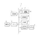
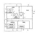
図1は、本実施形態における小規模診断システム1のシステム構成を示すものであり、図2は、小規模診断システム1を適用した場合の各装置の医療施設における配置例を示すものである。
FIG. 1 shows a system configuration of a small-
小規模診断システム1は、開業医やクリニック等の比較的小規模の医療施設に適用されるシステムであり、図1に示すように、画像生成装置2である超音波診断装置2a、内視鏡装置2b、CR(Computed Radiography)装置2cと、制御装置3と、サーバ4と、レセコン5とから構成されており、各装置は、例えば図示しないスイッチングハブ等を介してLAN(Local Area Network)等の通信ネットワーク(以下単に「ネットワーク」という)7に接続されている。なお、小規模診断システム1における各装置の台数は特に限定されないが、システム全体の制御を一箇所に集約して操作者の移動の手間を省くとの観点から、制御装置3は小規模診断システム1内に1つのみ設けられることが好ましい。
The small-
病院内の通信方式としては、一般的に、DICOM(Digital Image and Communications in Medicine)規格が用いられており、LAN接続された各装置間の通信では、DICOM MWM(Modality Worklist Management)やDICOM MPPS(Modality Performed Procedure Step)が用いられる。なお、本実施形態に適用可能な通信方式はこれに限定されない。 In general, DICOM (Digital Image and Communications in Medicine) standard is used as a communication method in a hospital, and DICOM MWM (Modality Worklist Management) or DICOM MPPS (DICOM MPPS) is used for communication between devices connected to a LAN. Modality Performed Procedure Step) is used. Note that the communication method applicable to this embodiment is not limited to this.
例えば、開業医やクリニック等のような小規模の医療施設においては、各装置は図2に示すように配置される。 For example, in a small-scale medical facility such as a medical practitioner or a clinic, each device is arranged as shown in FIG.
すなわち、まず入口10を入ると患者の受付けを行う受付11と待合室12がある。受付11には、窓口担当が配置され、来院した患者が受付11で受付けを行うことにより、当該窓口担当から受付順の受付番号が患者に付与される。このとき、例えば図示しない発券装置等により受付番号が印刷された受付番号札(受付票、又は診察券)等が発行されるようにしてもよい。
That is, when the
受付11には、保険点数計算、会計計算を行うレセプト用コンピュータ(以下「レセコン」と称する。)5が設置されている。前記窓口担当は、例えば、患者が受付けを行う際に患者の氏名を聞き取り、レセコン5を介して受付番号と患者氏名との対応付けを入力する。受付時に患者から提示された診察券や健康保険証書等に基づいて患者の性別、生年月日、年齢等を併せて入力してもよい。さらに、窓口担当は、患者の診察終了後にカルテ情報に基づいてレセコン5に保険点数計算に関する情報(以下「レセプト関連情報」と称する。)の必要事項を入力する作業も行う。
The
待合室12の隣には、ドア等を隔てて医師が患者の診察、診断等を行う診察室13が設けられている。例えば診察室13内の診察用のデスク(図示せず)の上には、医師が患者に関する情報(患者情報)等の入力を行ったり、撮影した画像をビューワ表示させて確認することのできる制御装置3と、撮影画像の画像データ等、各種の情報を蓄積する記憶手段としてのサーバ4が配置されている。診察室13内にはまた、プライバシー等の観点から隔離された空間で行う必要性の低い超音波診断装置2aが設置されている。
Next to the
また、廊下14を隔てて診察室13の向かい側にはX線撮影を行うX線撮影室15が設けられている。X線撮影室15内には、撮影装置22と読取装置23とから構成されるCR装置2cが配設されている。さらに、X線撮影室15の隣には検査室16が設けられており、検査室16内には内視鏡装置2bが配設されている。
Further, an
このように、本実施形態において、受付11のある待合室12、診察室13、X線撮影室15、検査室16は、同じフロアに位置しており、診察や撮影、検査を受ける患者は、受付けをして、診察室13に移動し、医師による問診を受け、撮影室15や検査室16に移動し、医師により指示された撮影・検査を行って、再度、診察室13に戻り、生成された撮影画像に基づき、医師の診察、診断を受けるまでの一連の動作を各室内及び廊下14という比較的短い距離を移動するだけで行うことができるようになっている。なお、各部屋及び各装置の配置は、図2に示したものに限定されない。
As described above, in this embodiment, the
以下、小規模診断システム1の各装置の構成について説明する。
画像生成装置2は、例えば、超音波診断装置2a、内視鏡装置2b、CR装置2c等の、患者の診断対象部位を被写体として撮影を行い、撮影した画像をデジタル変換して撮影画像の画像データ(撮影画像情報)を生成する画像生成手段(モダリティ)である。
Hereinafter, the configuration of each device of the small-
For example, the
超音波診断装置2aは、超音波を出力する超音波プローブと、超音波プローブに接続され、超音波プローブで受信された音波(エコー信号)を内部組織の撮影画像の画像データに変換する電子装置とから構成されている(いずれも図示せず)。超音波診断装置2aは、超音波プローブから体内に超音波を送り、体内組織に反射した音波(エコー信号)を再び超音波プローブで受信して、このエコー信号に応じた撮影画像を電子装置によって生成するようになっている。
The ultrasonic
超音波診断装置2aには、アナログ信号からデジタル信号への変換等を行う変換手段(コンバータ)である変換装置21が接続されており、超音波診断装置2aは、変換装置21を介してネットワーク7に接続されている。このように変換装置21を介することにより、ネットワーク7に接続された他の外部機器の規格(例えば通信プロトコル)等に合わない形式のデータが超音波診断装置2aから出力される場合でも適宜変換してネットワーク7に接続された外部機器との間でデータの送受信を行うことができる。
The ultrasonic
変換装置21には、例えば、テンキー、キーボード、タッチパネル等で構成される入力操作部21aが設けられている。入力操作部21aの構成はここに示したものに限定されず、例えば、カードを差し込むことでカードに書き込まれた情報を読み取るカードリーダや、バーコードを読み取るバーコードリーダのようなものでもよい。入力操作部21aは、撮影対象である患者と対応付けられて設定された検索用IDを入力し撮影された撮影画像の画像データに付帯させる情報付帯手段である。
The
ここで検索用IDとは、撮影後に撮影画像を検索する際、検査対象を識別する識別標識となるものであり、例えば、受付けを行ったときに付与される受付番号(患者ID)である。本実施形態における小規模診断システム1では、予め患者に対するオーダ情報(検査オーダ情報、撮影オーダ情報)を生成、発行せずに、患者の撮影を先行して行い、撮影画像の生成後、医師が患者情報と撮影画像とを対応付けるシステムであり、検索用IDはこの対応付け時に使用されるものである。
Here, the search ID is an identification mark for identifying an inspection object when searching for a captured image after imaging, and is, for example, a reception number (patient ID) assigned when receiving. In the small-
例えば、入力操作部21aが検索用IDとして受付番号を入力する場合、例えば、レセコン5で付与された受付番号が「00001」である患者を撮影する場合には、入力操作部21aから、患者に対応する検索用IDとして「00001」を入力する。
なお、本実施形態の小規模診断システム1を適用する開業医等の環境が、1日あたりの来院数が10〜40人程度である場合には、診察券(受付番号札)の通し番号は2桁あれば充分であるので、入力操作部21aはこの2桁の数値が入力できればよく、安価なテンキーが好ましい。
なお、以下においては、検索用IDとして受付番号を用いる場合を例として説明するが、後述するように、検索用IDは、受付番号に限定されない。
For example, when the
In addition, when the environment of a practitioner or the like to which the small-
In the following, a case where a reception number is used as a search ID will be described as an example. However, as will be described later, the search ID is not limited to a reception number.
なお、入力操作部21aから入力され撮影画像に付帯される情報は、検索用IDに限定されない。患者の氏名等、患者を識別する各種情報を入力操作部21aから入力するようにしてもよい。当該撮影を行った画像生成装置2に付与されている識別番号や当該撮影が造影剤等を用いない単純撮影か、造影剤を用いた撮影か等の撮影の種類を特定する情報等を入力するようにしてもよい。入力された検索用IDその他の情報はヘッダ情報等の付帯情報として撮影画像の画像データに付帯され、画像データが外部機器に送信されるときにはこれらの情報も画像データと対応付けられて送信される。
The information input from the
内視鏡装置2bは、可撓性を有する管の先端部に小型の撮影装置が設けられたものであり(いずれも図示せず)、撮影装置は例えば光学レンズ等で構成される対物光学系と、対物光学系の結像位置に配置された撮像部と、LED(Light Emitting Diode)等で構成され撮像を行うために必要な照明を行う照明部とを備えている(いずれも図示せず)。撮像部は、例えばCCD(Charge Coupled Device)、CMOS(Complementary Metal-Oxide
Semiconductor)等の固体撮像素子を備え、光が入射すると光の入射光量に応じた量の電気的な信号へと光電変換する。対物光学系は、照明部により照明された領域を光学レンズで集光し、撮像部が有する固体撮像素子に結像するように構成されており、固体撮像素子に入射した光が光電変換されることにより、電気信号として撮影画像の画像データが出力されるようになっている。
The
A solid-state imaging device such as a semiconductor) is provided, and when light is incident, photoelectric conversion is performed into an electrical signal having an amount corresponding to the amount of incident light. The objective optical system is configured to condense an area illuminated by the illuminating unit with an optical lens and form an image on a solid-state imaging device included in the imaging unit, and light incident on the solid-state imaging device is photoelectrically converted. As a result, the image data of the captured image is output as an electrical signal.
CR装置2cを構成する撮影装置22は、図示しない放射線源を有し、検査対象(図示せず)に放射線を照射して静止画像を撮影する。撮影時には前記放射線源から照射される放射線の照射領域内に、例えば放射線エネルギーを蓄積する輝尽性蛍光体シートを備える放射線画像変換プレートが内蔵された放射線画像変換媒体(いずれも図示せず)が配置されるようになっており、放射線源からの照射放射線量に対する検査対象の放射線透過率分布に従った放射線量が放射線画像変換媒体に内設された輝尽性蛍光体シートの輝尽性蛍光体層に蓄積し、この輝尽性蛍光体層に検査対象の放射線画像情報を記録する。
The
読取装置23は、検査対象の放射線画像情報が記録された放射線画像変換媒体を装填し、放射線画像変換媒体から検査対象の放射線画像情報を読み取って撮影画像を生成する装置であり、前記制御装置3からの制御信号に基づいて、装置内に装填された放射線画像変換媒体の輝尽性蛍光体シートに励起光を照射し、これによりシートから発光される輝尽光を光電変換し、得られた画像信号をA/D変換して、撮影画像を生成するようになっている。
なお、CR装置2cは撮影装置22と読取装置23とが一体化した一体型の装置であってもよい。
The
The
なお、図示はしないが、内視鏡装置2b、CR装置2cの読取装置23にも超音波診断装置2aにおける変換装置21の入力操作部21aと同様に撮影の際に画像データに検索用IDを付帯させる内蔵又は外部接続された情報付帯手段が設けられており、生成した撮影画像の画像データに当該患者の検索用IDを付帯させるようになっている。
Although not shown, the
なお、情報付帯手段から入力される検索用IDとしては、前述の入力操作部21aと同様に、例えば、前記受付番号等が使用される。前述のように、本実施形態の小規模診断システム1を適用する開業医等の環境が、1日あたりの来院数が10〜40人程度である場合には、診察券(受付番号札)の通し番号は2桁あれば充分で、情報付帯手段はこの2桁の数値が入力できればよく、安価なテンキーが好ましい。
Note that, for example, the reception number is used as the search ID input from the information-accompanying means, similarly to the
また、変換装置21、内視鏡装置2b及びCR装置2cの読取装置23は、DICOM規格に準じた形式で小規模診断システム1内の画像データを特定するための個別ID(以下「UID」(Unique ID)と称する。)を生成された画像データに自動的に付与する機能を備えていてもよい。変換装置21、内視鏡装置2b及びCR装置2cの読取装置23がこのような機能を備えている場合には、付与されたUIDは画像データに付帯され、画像データが外部機器に送信されるときにはこれらの情報も画像データと対応付けられて送信される。
The
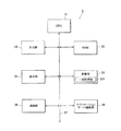
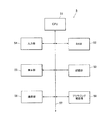
制御装置3は、例えば診察室13に設置され、医師が画像等を表示させて読影診断等を行うためのワークステーション(PC:Personal Computer)であり、一般的なPCよりも高精細のモニタ(表示部)を備えるものであってもよい。制御装置3は、図3に示すように、CPU31、RAM32、記憶部33、入力部34、表示部35、通信部36、及びアプリケーションサーバ機能部38等を備えて構成されており、各部はバス37により接続されている。
The
CPU31は、記憶部33に記憶されているシステムプログラムや処理プログラム等の各種プログラムを読み出してRAM32に展開し、展開されたプログラムに従って後述する画像処理や画像処理の完了した撮影画像情報と患者情報との対応付け処理をはじめとする各種処理を実行するようになっている。
The
記憶部33は、HDD(Hard Disc)や半導体の不揮発性メモリ等により構成される。記憶部33には、前述のように各種プログラムが記憶されているほか、特開H11−85950や特開2001−76141の明細書中に開示されているような撮影部位を識別するための部位識別パラメータ(撮影画像に現われた撮影対象の輪郭、形状等と撮影部位とを対応付けるルックアップテーブル等)及び識別された撮影部位に応じた画像処理を行う画像処理パラメータ(階調処理に用いる階調曲線を定義したルックアップテーブル、周波数処理の強調度等)等が記憶されている。
The
また、記憶部33には、前記各種の画像生成装置2によって生成された撮影画像の画像データが一時的に記憶される一時記憶部331を備えている。なお、画像データに検索用IDや患者情報、撮影の種類に関する情報、撮影を行った画像生成装置2を識別する情報等が付帯しているときは、撮影画像の画像データとこれらの情報とを対応付けて記憶する。その他、記憶部33には、患者の受付順に作成された患者リスト等、制御装置3に送られた各種情報が記憶される。
In addition, the
入力部34は、例えば図示しないカーソルキー、数字入力キー、及び各種機能キー等を備えたキーボードと、マウス等のポインティングデバイスを備えて構成されており、撮影対象である患者を特定する患者情報である患者氏名等を入力可能となっている。入力部34は、キーボードに対するキー操作やマウス操作等により入力された指示信号をCPU31に出力するようになっている。
The
ここで、入力部34から入力される患者情報としては、例えば患者の氏名、診察券番号等が挙げられるが、患者情報はここに例示したものに限定されない。また、検索用IDとは、前述のように撮影後に撮影画像を検索する際、検査対象を識別する識別標識となるものであり、例えば受付けを行ったときに付与される受付番号である。なお、本実施形態においては、患者情報として患者氏名を入力する例について説明する。
Here, examples of the patient information input from the
表示部35は、例えば、CRT(Cathode Ray Tube)やLCD(Liquid Crystal Display)等のモニタを備えて構成されており、後述するように、撮影画像、撮影画像から生成される確定撮影画像、各種の患者情報等を表示する表示手段である。表示部35は、CPU31から入力される表示信号の指示に従って、各種画面を表示する。
The
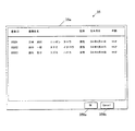
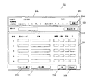
本実施形態においては、例えば、医師等が患者リストを表示するように指示する指示信号を入力部34から入力すると、図4に示すような患者リスト画面35aが表示される。なお、後述するように患者リストが更新されたときは、更新された患者リストが患者リスト画面35aに表示される。患者リスト画面35aには、図4に示すように例えば患者ID、患者氏名、性別、生年月日、年齢等、患者リストの内容が表示されるようになっている。また、患者リスト画面35aには患者を選択する「OKボタン」359a、一旦患者を選択した後に選択を解除する「Cancelボタン」359b等が設けられており、患者リスト画面35aを介して患者リスト上の患者を選択することができるようになっている。なお、患者リスト画面35aの表示内容等は、図示例に限定されない。
In this embodiment, for example, when a doctor or the like inputs an instruction signal for instructing to display a patient list from the
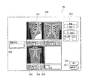
また、本実施形態においては、例えば、医師等が画像生成装置である超音波診断装置2a、内視鏡装置2b、CR装置2cから取得した撮影画像を表示するように指示する指示信号を入力部34から入力すると、図5に示すような画像確認画面35bが表示される。
In the present embodiment, for example, a doctor or the like inputs an instruction signal instructing to display a captured image acquired from the ultrasound
図5に示すように、画像確認画面35bには、前記各種の画像生成装置2によって生成された撮影画像を表示するための画像表示欄351と、画像処理条件の調整指示を入力するための画像処理条件調整欄352とが設けられている。また、画像表示欄351には、画像表示欄351の各表示欄に対応して設けられ、各表示欄に表示された撮影画像を確定し、当該撮影画像の画像データを確定後の画像データとして記憶するためのOKボタン353と、各表示欄に表示された撮影画像の画像データの破棄及び再出力を指示するためのNGボタン354と、各撮影画像について患者のどの部位を撮影したものであるかを自動部位認識した結果、判断された撮影部位を表示する撮影部位表示欄355とが配置されている。なお、確定後の撮影画像の画像データを保存した場合には、画像表示欄351の各表示欄に保存済みのマーク等が表示されるようにしてもよい。
As shown in FIG. 5, on the
また、画像確認画面35bには、患者情報として患者氏名を入力、表示する患者氏名欄356が設けられている。なお、本実施形態においては、患者情報の入力、表示欄として患者氏名欄356を設けた場合を例として以下説明するが、患者情報の入力、表示欄はここに例示したものに限定されない。
The
その他、画像確認画面35bには、診断を終了するための診断終了ボタン357や前の表示画面に戻るための戻るボタン358等が設けられている。なお、画像確認画面35bの構成は図5に例示したものに限定されない。例えば、これら以外の表示欄やボタンが設けられていてもよく、前記患者リストに対応した受付番号を表示する欄等が設けられていてもよい。
In addition, the
通信部36は、ネットワークインターフェース等により構成され、スイッチングハブを介してネットワーク7に接続された外部機器との間でデータの送受信を行う。即ち、通信部36は、画像生成装置2によって生成された撮影画像の画像データを受信し、また、必要に応じてサーバ4等の外部装置に画像処理の完了した確定後の撮影画像の画像データを送信するものである。
The
また、アプリケーションサーバ機能部38は、ネットワークを介して情報の送受信を行うアプリケーションサーバとして機能するものであり、例えばWebブラウザを用いて閲覧可能であり、HTTP(HyperText Transfer Protocol)で通信するWebアプリケーションサーバとして機能する。アプリケーションサーバ機能部38は、後述するブラウジング機能部58(図6参照)からの要求にしたがって、入力画面55a(図7参照)を送信する入力画面送信手段、ネットワークを介して送信された情報画面55b(図8参照)を受信する情報画面受信手段等を備えている。アプリケーションサーバ機能部38は、後述する情報画面55b(図8参照)に記載されている情報を抽出する情報抽出機能を有するアプリケーションソフト(図示せず)を立ち上げるようになっている。アプリケーションソフトの情報抽出機能によって抽出された情報は、CPU31に取得されて記憶部33に記憶される。
The application
次に、CPU31によって行われる各種処理について説明する。
Next, various processes performed by the
本実施形態において、CPU31は、検索用IDに基づいて、記憶部33に記憶された撮影画像の中から特定の患者について撮影された撮影画像だけを抽出するようになっている。すなわち、前述のように、撮影の際には当該撮影の検査対象である患者の患者情報と対応付けられて設定された検索用IDが入力操作部21a等から入力され、この検索用IDは、例えば撮影画像の画像データにヘッダ情報として付帯している。医師等の操作者が、ある検索用IDに対応する撮影画像を抽出するように指示する指示信号を入力部34等から入力すると、CPU31は、記憶部33に記憶された撮影画像のうち、当該検索用IDが付帯している撮影画像を検索し抽出して表示部35の画像確認画面35b等に表示する。
In the present embodiment, the
また、CPU31は、画像生成装置2によって生成され、通信部36によって受信した撮影画像の画像データについて撮影部位に応じた画像処理を行い、診断に適した診断用の撮影画像を生成する画像処理手段として機能する。
具体的には、CPU31は、まず、記憶部33から部位識別パラメータを読み出して画像生成装置2によって生成された撮影画像に現われた撮影対象の輪郭、形状等から撮影部位を識別する部位自動識別処理を行う。撮影画像の部位が識別されると、CPU31は、撮影部位に対応する画像処理パラメータを記憶部33から読み出して、読み出したパラメータに基づいて画像処理条件を決定し、決定した画像処理条件で画像データに画像のコントラストを調整する階調処理、濃度を調整する処理、鮮鋭度を調整する周波数処理等の画像処理を施す。さらに、医師等の操作者が画像処理条件調整欄352から撮影画像の濃度やコントラスト等を調整する入力を行うと、CPU31は、これに応じて撮影画像の画像処理を行う。そして、画像処理が完了してOKボタン353が押下されると、CPU31は、画像処理後の撮影画像の画像データを診断用の撮影画像の画像データとして決定する。
In addition, the
Specifically, the
さらに、CPU31は、撮影された検査対象を特定する患者情報が入力されたときは、この患者氏名等の患者情報を検索用IDと置き換え、当該患者情報を所定の画像処理後の撮影画像の画像データとを対応付ける。CPU31は、患者情報と対応付けられた撮影画像の画像データを記憶部33又はサーバ4の画像DB41に書込み、記憶させる。
Further, when patient information specifying a photographed examination object is input, the
また、CPU31は、前述のようにアプリケーションソフトの情報抽出機能によって抽出された情報を取得し、記憶部33に記憶させるとともに、この情報に基づいて診療結果情報を生成する診療結果情報生成手段として機能する。
Further, the
ここで診療結果情報とは、患者ID、患者氏名等の患者情報と、傷病名、今回どのような撮影や検査を行い、そのような薬剤を投薬したのか等の診療内容等を含む各種情報であり、患者に対して今回行った診療行為に関する情報である。さらに、CPU31は、生成された診療結果情報を撮影画像の画像データと対応付ける対応付け手段として機能し、対応付けた診療結果情報と撮影画像の画像データとを記憶部33又はサーバ4の画像DB41に書込み、記憶させる。また、生成された診療結果情報を、通信部を介してレセコン5に送信するようになっている。
Here, the medical treatment result information is various information including patient information such as patient ID and patient name, injury and illness name, medical treatment contents such as what kind of imaging and examination were performed and such medicine was administered, etc. Yes, it is information regarding the medical practice performed on the patient this time. Furthermore, the
次に、サーバ4は、CPU(Central Processing Unit)、RAM(Random Access Memory)、HDD等により構成され各種プログラム等を格納する記憶部、入力部、表示部、ネットワーク7に接続された各装置との間で情報の送受信を行う通信部(いずれも図示せず)等を備えて構成されたコンピュータである。
Next, the
サーバ4は、通信部を介して制御装置3から送信された撮影画像の画像データ等を記憶するデータベースとして画像DB41を備えている。サーバ4は、前記CPUと記憶部に格納されているプログラムと協働して処理を行うことにより、通信部を介して制御装置3から書込み指示された撮影画像の画像データ及びその付帯情報(患者情報及びUIDを含む情報)を対応付けて画像DB41に格納するようになっており、画像DB41は、後述するレセプト関連情報、患者情報等の付帯情報と、撮影画像の画像データとを対応付けて記憶するようになっている。
The
また、サーバ4は、制御装置3からの要求に応じて画像DB41を検索し、要求に応じた画像データを読み出して当該撮影画像の画像データとこれに付随する付帯情報とを制御装置3に送信する。
Further, the
また、レセコン5は、図6に示すように、CPU(Central Processing Unit)51、RAM(Random Access Memory52)、HDD等により構成され各種プログラム等を格納する記憶部53、キーボードやマウス等により構成される入力部54、CRTやLCD等により構成される表示部55、ネットワーク7に接続された各装置との間で情報の送受信を行う通信部56、ネットワーク上の各種サーバを閲覧可能なブラウジング機能部58等を備えて構成されたコンピュータであり、各部はバス57により接続されている。
Further, as shown in FIG. 6, the
レセコン5は、診断後医師からの紙カルテ等に基づいて前記窓口担当等の操作者により入力された患者に関するレセプト関連情報を記憶するレセプトDB(database)6を備えている。
レセプトDB6は、来院した患者に関するレセプト関連情報を患者情報と対応付けて格納するレセプト情報記憶手段として機能するデータベースである。レセプトDB6には、各患者の受付日付、当該受付日において患者に付与された検索用IDである受付番号、患者情報としての患者氏名、同じ受付日付において当該患者について撮影された画像の撮影数、造影剤を用いた撮影の枚数である造影数、撮影を行った画像生成装置2の種類であるモダリティ種別、撮影がどの部位について行われたものかを示す撮影部位、同じ受付日付において当該患者に処方された薬剤の投薬情報等が関連付けられて記憶されている。
The
The
レセコン5のCPU51は、入力部54から入力された情報に基づいて患者リストを生成するリスト生成手段として機能する。患者リストは、例えば各患者を特定するための識別情報である患者ID(本実施形態では患者の受付番号)と、これに対応する患者氏名、性別、生年月日、年齢等が、受付番号の早い順にリスト状に列記されたものである。CPU51によって生成された患者リストは、通信部56を介して制御装置3に送信されるようになっており、通信部56は患者リストを送信するリスト送信手段として機能する。
The
レセコン5の表示部55及びレセコン5から患者リストを送信された制御装置3の表示部35は、患者リストを一覧表示させた患者リスト画面35a(図4参照)を表示させることができる。患者リスト画面35aに表示された患者のうち、特定の患者を入力部から選択することにより、患者リスト画面35aを介してレセプト関連情報を入力する特定の患者が選択されるように構成されてもよい。また、前記受付入力画面を介して入力部54から新たな受付番号及び患者氏名等が入力されると患者リスト画面35aの表示が更新され、新たに入力された受付番号及び患者氏名が受付日付ごとの受付番号順にリストに追加されるようになっている。レセコン5の側で患者リストが更新された場合には、更新内容が制御装置3に送信され、制御装置3の記憶部33に記憶されている患者リストもこれと同期して更新されるようになっている。
The
なお、本実施形態においては、患者のレセプト処理(会計処理)が終了すると、当該患者についての表示がリストから削除され、順次次の受付番号の患者が繰り上がり、リストが更新されるようになっている。なお、レセプト処理(会計処理)が終了した際の患者リストの更新は、自動的に行われる場合に限定されず、レセプト処理が終了したことを確認すると受付担当が当該患者を患者リストから削除する指示を入力部から入力することにより患者リストの更新が行われるように構成してもよい。 In this embodiment, when the patient's receipt process (accounting process) is completed, the display about the patient is deleted from the list, and the patient with the next reception number is sequentially advanced, and the list is updated. ing. The update of the patient list when the receipt process (accounting process) is completed is not limited to the case where it is automatically performed. Upon confirming that the receipt process is completed, the receptionist deletes the patient from the patient list. The patient list may be updated by inputting an instruction from the input unit.
レセコン5の入力部54は、受付けを行うための画面を表示するよう指示を入力可能であり、受付けを行うための画面を表示するよう指示が入力されると、CPU51が記憶部53に格納されたプログラムと協働して処理を行うことにより、受付入力画面(図示せず)を表示部55に表示させる。受付入力画面に表示される項目は特に限定されないが、例えば受付日付欄、受付番号欄、患者氏名欄等が挙げられる。なお、患者の性別、生年月日、年齢等を入力する欄が設けられていてもよい。また、このうち受付日付欄は、受付番号欄、患者氏名欄等を入力すると当該入力操作を行った日付が自動的に入力されるようになっていてもよい。
The
入力部54は、この表示部55に表示された受付入力画面を介して、新たな来院患者についての各患者に対応し患者を特定可能な識別情報としての受付番号(検索用ID)と患者情報としての患者氏名とを入力可能となっている。なお、前述のように、患者が受付の際に診察券や健康保険証書等を提示した場合には、これらに記載されている患者情報(患者の性別、生年月日、年齢等)を併せて入力するようにしてもよい。レセコン5によってレセコン5の受付入力画面及び入力部54により患者情報入力手段が構成される。入力部54により受付番号及び患者氏名が入力されると、入力が行われた日付(受付日付)とともに、受付番号及び患者氏名がレセプトDB6に記憶される。
Via the reception input screen displayed on the
また、ブラウジング機能部58は、ネットワーク上に接続されている各種サーバを閲覧するブラウジング機能を有するブラウジング手段である。ブラウジング機能部58は、所定の制御プログラムに従い、Webアドレスに基づいてWebページへのアクセスを行うとともに、アクセス先からの情報を取得するようになっている。
The
本実施形態においては、入力部54よりレセプト関連情報を入力する入力画面を表示するよう指示が入力されると、ブラウジング機能部58は、制御装置3のアプリケーションサーバ機能部38にアクセスし、アプリケーションサーバ機能部38に対して入力画面55a(図7参照)を送信するよう要求するようになっており、入力画面55aを受信する入力画面受信手段として機能する。また、ブラウジング機能部58は、入力画面55aに必要な情報を入力した情報画面55b(図8参照)を制御装置3に対して送信する情報画面送信手段として機能する。
In the present embodiment, when an instruction to display an input screen for inputting receipt related information is input from the
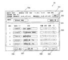
図7は、制御装置3から送信される入力画面55aの一例であり、図8は、入力画面55aに必要な情報を入力した情報画面55bの一例である。レセコン5の表示部55は、入力画面55a及び情報画面55bを表示する画面表示手段として機能する。また、前記入力部54は、この表示部55の入力画面55aを介して入力画面55a上の項目に当該患者に関するレセプト関連情報を入力可能となっており、レセコン5の入力画面55a及び入力部54によりレセプト関連情報を入力する情報入力手段が構成される。
FIG. 7 is an example of an
図7及び図8に示すように、入力画面55a及び情報画面55bには、患者IDや患者氏名、性別、保険情報、来院情報等を入力する患者情報入力欄551、傷病名を入力する傷病名入力欄552、診療における加算事項の有無、投薬状況等、保険点数計算に必要な各種レセプト情報を入力するレセプト情報入力欄553等が設けられている。このうちレセプト情報入力欄553は、診療コード又は名称を入力すると、当該診療コード又は名称に対応する情報が自動的に他の項目に入力されるようになっている。例えば、診療コード欄に「112009210」と入力すると、図8に示すように、名称欄に「再診(診療所)」、点数欄に「73」、回数欄に「1」、計の欄に「73」との情報がそれぞれ自動的に入力される。
As shown in FIGS. 7 and 8, the
患者情報入力欄551には来院履歴等、さらに詳細な情報を参照するための詳細ボタン554が設けられている。また、傷病名入力欄552や、レセプト情報入力欄553の診療コード欄、名称欄等、複数の選択肢の中から選択することができる項目については、予め用意されたプルダウンメニューを表示させる「傷病名一覧ボタン」555、「コード一覧ボタン」556、「名称一覧ボタン」557が設けられている。入力を行う受付担当は、これらのボタンを操作することにより表示されるプルダウンメニューの中から当てはまるものを選択することにより簡易に入力を行うことができる。なお、「傷病名一覧ボタン」555、「コード一覧ボタン」556、「名称一覧ボタン」557を操作するとダイアログボックスが表示され、表示される指示等に従って必要項目の選択、指定を行うことができるように構成してもよい。
The patient
また、入力画面55a及び情報画面55bには、入力内容を確定させる「OKボタン」558と、入力をやり直す際の「Cancelボタン」559とが設けられている。OKボタン558を操作すると、各項目に情報が入力された情報画面55bがネットワークを介して制御装置3のアプリケーションサーバ機能部38に送信され、アプリケーションサーバ機能部38の情報画面受信部によって受信される。
Further, the
レセコン5のCPU51は、入力部54から入力された情報に基づいて保険点数を演算するとともに、受付番号及び患者氏名と当該患者に関するレセプト関連情報とを対応付けてレセプトDB6に記憶させる。
The
なお、本実施形態においては、受付時に受付入力画面55aから受付番号及び患者氏名を入力することとしたが、受付時には当該患者に対して発行した受付番号のみを入力し、患者氏名はレセプト関連情報入力画面55bを介して入力するようにしてもよい。すなわち、レセプト情報入力手段が患者情報入力手段を含む構成としてもよい。また、患者情報として患者氏名の他患者の性別、年齢、保険番号等の詳細な情報を入力する場合には、患者情報のうち、患者氏名のみを受付時に受付入力画面55aから入力し、その他の詳細な情報はレセプト関連情報入力画面55bから入力ようにしてもよい。
In this embodiment, the reception number and patient name are input from the
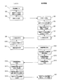
次に、図9を参照しつつ、本実施形態における小規模診断システム1の動作について説明する。
Next, the operation of the small-
まず、受付11において来院した患者に対して受付番号が付与され、受付番号札が発行される。窓口担当が患者氏名等の聞き取りを行い、レセコン5の図示しない受付入力画面を介して入力部54から患者IDである受付番号、患者氏名等の患者情報の入力を行う(ステップS1)。受付番号及び患者氏名の入力が行われると、レセプトDB6に新規レコードが追加され、受付番号及び患者情報が書込まれる。また、レセコン5は、患者を受け付けると受付順に患者を列記する患者リストを生成するようになっており、新たに受け付けをすると、当該患者の患者情報を患者リストに追加して患者リストを更新する(ステップS2)。レセコン5は、患者リスト及びその更新情報を、通信部を介して随時制御装置3に送信する(ステップS3)。
First, a reception number is given to a patient who visits at the
制御装置3は、レセコン5から患者リストを受信すると(ステップS4)、記憶部33に患者リストを記憶する。なお、すでに患者リストを受信して、新たにその更新情報を受信した場合には、記憶部33に記憶されている患者リストにレセコン5から送られた患者情報を追加して患者リストを更新する。受付番号(患者ID)が付与された患者が診察室13に移動すると、医師は、制御装置3の表示部35に患者リスト画面35a(図4参照)を表示させて、当該受付番号(患者ID)に対応する患者をリストの中から選択する(ステップS5)。
When receiving the patient list from the receptacle 5 (Step S4), the
医師は、患者に対し問診を行い、実施する撮影、検査を決定する。問診により患部の撮影が必要であると決定された場合には、医師や撮影技師等、撮影を行う撮影実施者は、患者を撮影に用いる画像生成装置2のもとに連れて行き、画像生成装置2の入力操作部から当該患者に付与された検索用IDとしての受付番号(患者ID)の入力を行う。例えば、画像生成装置2として超音波診断装置2aを用いる場合には、撮影実施者は入力操作部から患者の受付番号(患者ID)を入力する。その後、当該患者の診断対象部位を被写体として撮影を行い、画像生成装置2により撮影画像の画像データが生成される。また、例えば、画像生成装置2としてCR装置2cを用いる場合には、撮影後に撮影実施者は読取装置に設けられた入力部のテンキー等から検索用IDとして患者の受付番号(患者ID)を入力する。なお、予めその日に検査予約をしていた場合には、医師による問診を受けずに受付から直接撮影室15又は検査室16に移動してもよい。この場合には、撮影又は検査後に患者が診察室に移動した際に患者から受付番号(患者ID)を聞き、患者リストから当該患者を選択する。
The doctor interrogates the patient and decides the imaging and examination to be performed. When it is determined that the affected area needs to be photographed through an inquiry, a photographing person who performs photographing, such as a doctor or a photographing engineer, takes the patient to the
なお、ある患者を選択した後、別の患者をさらに選択してもよい。この場合には、選択された患者を順次又は各画像生成装置2を用いて同時並行的に撮影する。この場合でも、画像生成装置での撮影時に、検索用IDとして患者の受付番号(患者ID)が入力されるので、画像データに付帯された受付番号(患者ID)と照合することにより、撮影後に患者と画像データとの対応付けを行うことが可能である。
In addition, after selecting a certain patient, you may further select another patient. In this case, the selected patients are photographed sequentially or in parallel using the
撮影が終了すると、生成された撮影画像の画像データが、入力された検索用ID等の付帯情報が付帯された状態でネットワーク7を介して制御装置3に送られる(ステップS6)。なお、緊急時等、受付を経由していない患者を撮影する場合には、受付番号(患者ID)に代えて、予め緊急割込みを示す所定のコード、例えば、「99」のように、普段の撮影時には現われないような番号を検索用IDとして設定しておくことにより、通常のフローと同様に撮影後の画像データを他の画像データと区別して抽出することが可能となる。
When shooting is completed, the image data of the generated shot image is sent to the
画像生成装置2から撮影画像の画像データが制御装置3に送られると、CPU31は撮影を行った部位を自動的に識別する。そして、撮影部位を識別すると、CPU31は当該撮影部位に応じた画像処理条件を決定し、撮影画像の画像データについて当該条件に応じた画像処理を行う。画像処理が行われると、撮影画像は画像データに付帯する各種の情報とともに一旦、記憶部33の一時記憶部331に記憶される。
When image data of a photographed image is sent from the
撮影又は検査後に医師が患者を診察する際には、医師は制御装置3の入力部34を操作することにより表示部35に図示しない画像検索画面を表示させ、患者の受付番号(検索用ID)を確認して患者の受付番号を入力部34から入力する。検索用IDである受付番号を入力すると、CPU31は当該受付番号を検索キーとして、当該患者に対応する画像を記憶部33の一時記憶部331から抽出し、抽出された撮影画像は表示部35の画像確認画面35b(図5参照)に一覧表示される。医師は患者の氏名を聴取して患者情報である患者氏名を患者情報入力欄356から入力する。患者情報入力欄356を介して入力部34から当該患者に関する患者情報の入力が行われると、表示されている撮影画像の画像データの付帯情報として当該入力された患者情報が書込まれる。
When the doctor examines the patient after imaging or examination, the doctor operates the
医師は、画像確認画面35bで撮影画像の画像データを確認し、問題がなければOKボタン353により当該撮影画像を診断用の撮影画像として確定させる。他方、撮影画像の画像処理に問題がある場合には、医師等の操作者は、画像処理条件調整欄352で撮影画像の濃度やコントラスト等の調整を行う。なお、撮影部位に応じた画像処理が適切に行われなかった場合には、画像処理条件調整欄352で行った撮影画像の濃度やコントラスト等の調整を画像処理パラメータに反映させてパラメータの補正を行うようにしてもよい。また、各表示欄に表示された撮影画像が不鮮明である等、濃度やコントラスト等の調整のみでは調整できない場合には、撮影画像の画像データの破棄及び再出力を指示するためのNGボタン354を操作して当該撮影画像の画像データを破棄し画像生成装置2から画像データを再出力させる。
The doctor confirms the image data of the photographed image on the
医師は撮影画像の画像データを確定した後、当該撮影画像を見ながら診断を行い、患者に関する所見(診断された傷病命名等)、当該患者に処方する薬剤を示す投薬情報、当該患者に行った撮影や検査等に関する情報(撮影を行った装置の種類、撮影枚数、造影剤使用の有無、撮影部位、撮影方向、検査種別、検査ID等)を紙カルテに記録する。医師は紙カルテ等に診断所見を記入するとともに、入力された当該患者情報と撮影画像の画像データとを対応付けて(当該患者情報を付帯情報として)、サーバ4の画像DB41等の記憶手段に記憶する(ステップS7)。
After confirming the image data of the photographed image, the doctor made a diagnosis while looking at the photographed image, performed findings on the patient (names of diagnosed wounds, etc.), medication information indicating the drug prescribed to the patient, and the patient. Information related to imaging, examination, etc. (type of imaging apparatus, number of imaging, presence / absence of use of contrast medium, imaging site, imaging direction, examination type, examination ID, etc.) is recorded on a paper chart. The doctor writes the diagnostic findings on a paper chart and the like, associates the inputted patient information with the image data of the captured image (the patient information is used as supplementary information), and stores it in the storage means such as the
医師は紙カルテへの所見記載後、当該紙カルテを受付11の窓口担当に渡す。窓口担当は、レセコン5の入力部54から入力画面55a(図7参照)を表示部55に表示させるよう指示を入力する。これによりブラウジング機能部58が動作して制御装置3のアプリケーションサーバ機能部38にアクセスし、制御装置3のアプリケーションサーバ機能部38に対して入力画面55aを送信するよう要求する。ブラウジング機能部58からの要求があると、アプリケーションサーバ機能部38は入力画面送信手段により入力画面55aをレセコン5に送信する(ステップS8)。
After describing the findings on the paper chart, the doctor gives the paper chart to the reception desk at the
アプリケーションサーバ機能部38から入力画面55aを受信すると(ステップS9)、窓口担当は、入力部54を操作することにより、紙カルテに記載されている情報を入力画面55aを介して入力画面55aの各項目に入力して(ステップS10)、情報画面55b(図8参照)を生成する。必要項目が入力され情報画面55bが生成されると、レセコン5のブラウジング機能部58が制御装置3のアプリケーションサーバ機能部38に情報画面55bを送信する(ステップS11)。制御装置3のアプリケーションサーバ機能部38がブラウジング機能部58により送信された情報画面55bを受信すると(ステップS12)、CPU31は情報画面55bから情報を抽出し診療結果情報を生成する(ステップS13)。CPU31は生成された診療結果情報を撮影画像の画像データや患者情報と対応付けて記憶部33等に記憶(格納)させるとともに(ステップS14)、通信部36を介して診療結果情報をレセコン5に送信する(ステップS15)。レセコン5は診療結果情報を受信すると(ステップS16)、この診療結果情報に基づいて会計計算処理を行う(ステップS17)。
When the
会計計算処理が終了すると、CPU51は当該患者を患者リストから削除し患者リストを更新する(ステップS18)。そして、患者リストの更新情報を通信部56を介して制御装置3に送信する(ステップS19)。制御装置3は、患者リストの更新情報を受信すると、当該情報に従って患者リストを更新する(ステップS20)。
When the accounting calculation process ends, the
以上のように、本実施形態に係る小規模診断システム1によれば、制御装置3の側にアプリケーションサーバ機能部38を備え、レセコン5の側にブラウジング機能部58を備えて、レセコン5に蓄積される電子化された情報である患者情報やレセプト関連情報等をWebサーバ機能を用いて制御装置3に送ることができる。これにより、医師等がキーボード入力作業等を行うことなく、電子化されたレセプト関連情報を活用して診療結果情報を生成することができる。
As described above, according to the small-
また、患者リストを生成し、医師がレセコンで生成される患者リストから患者を選択すれば、当該患者の患者情報と撮影画像の画像データとが対応付けられるので、簡易な手法により患者情報と画像データとの対応付けを行うことができる。さらに、新たに患者を受け付けたときや患者の診療処理が終了したときには患者リストを更新するので、院内に滞留する患者の動向を容易に把握することができる。 Also, if a patient list is generated and the doctor selects a patient from the patient list generated by the receipt computer, the patient information of the patient and the image data of the captured image are associated with each other. Correlation with data can be performed. Furthermore, since the patient list is updated when a new patient is received or when the patient's medical treatment process is completed, it is possible to easily grasp the trend of patients staying in the hospital.
さらに、撮影画像を制御装置3の表示部35に表示させて診断を行うため、診断及び撮影画像の保存等においてフィルムを使用せずに済み、省コスト化を実現することができる。
Furthermore, since the photographed image is displayed on the
また、超音波診断装置2a、内視鏡装置2b、CR装置2cといった複数種類の画像生成装置2を備えているので、最低限必要な撮影、検査を行うことができる。また、複数の患者に対して同時並行的に撮影を行うことが可能であり、診察の効率を上げることができる。
Further, since a plurality of types of
さらに、画像生成装置2である超音波診断装置2aには変換手段21が接続されているので、超音波診断装置2aが、小規模診断システム1を適用する各施設に備えられた既存の装置等の規格に合わない画像データを出力する場合でも画像データを適宜変換して適用させることができる。このため、既存の装置をそのまま用いることができ、設備投資等の負担を要しない。
Furthermore, since the converting
また、患者を識別する患者情報と対応付けられた検索用IDで撮影画像を検索、抽出して、撮影画像と患者との対応付けがなされるので、受付けを行わずに撮影等を行った場合でも、当該患者に対して何枚の画像撮影を行ったか等、適切に会計関連情報を発生させることが可能となる。 In addition, when a photographed image is searched and extracted with a search ID associated with patient information for identifying a patient, and the photographed image and the patient are associated with each other. However, it is possible to appropriately generate accounting-related information such as how many images have been taken for the patient.
なお、本実施形態においては、患者の患者情報とこれに対応する検索用IDとを入力部34から入力し、撮影時に検索用IDを撮影画像の画像データに付帯させることにより患者と撮影画像とを対応付けるように構成したが、患者と撮影画像とを対応付けることができるものであれば、その構成は特に限定されない。
In the present embodiment, the patient information of the patient and the search ID corresponding thereto are input from the
例えば、撮影前には、患者リストの中から患者を選択することにより受付番号等、各患者に割り当てられた検索用IDを設定するに止め、患者氏名等の患者情報は、撮影後、制御装置3の表示部35で当該患者に対応する撮影画像を見ながら患者の診断を行う際に入力するようにしてもよい。 For example, prior to imaging, by selecting a patient from the patient list, the search ID assigned to each patient, such as an acceptance number, is set, and patient information such as patient name is 3 may be input when diagnosing a patient while viewing a captured image corresponding to the patient.
さらに、撮影前には患者の選択等を一切行わずにまず撮影を行い、その際、医師等の操作者が当該撮影対象となった患者を識別するものとして任意に定めた検索用IDを画像生成装置2で入力するようにしてもよい。この場合には、撮影後に制御装置3で未確定フォルダから撮影によって得られた画像データを開き、撮影画像を抽出したい患者の検索用IDを入力部34から入力する。そして、この検索用IDに基づいて当該患者について撮影された撮影画像を抽出し、制御装置3の表示部35に表示させた上で、当該撮影画像を見ながら患者の診断を行うとともに、当該患者の患者情報を入力してもよい。
Further, before imaging, the patient is first imaged without selecting any patient, and at that time, an operator ID such as a doctor images a search ID arbitrarily defined as identifying the patient to be imaged. You may make it input with the production |
また、複数の患者を同時並行的に撮影することがないような場合には、制御装置3の表示部35上で患者リストの中から患者を選択すると自動的に表示部35の表示画面が画像確認画面35bに切り替わり、撮影が行われると、当該画像確認画面35b上に当該患者を撮影した撮影画像が表示されるようにしてもよい。この場合には、患者リストの中から選択された患者と撮影を行った患者とが1対1で対応付けられるので、撮影前に検索用ID等を入力しなくても患者と撮影画像の取り違えを生じるおそれがない。このため、入力操作を最小限に抑えて医師等の負担を軽減することができる。
When a plurality of patients are not photographed in parallel, when the patient is selected from the patient list on the
なお、本実施形態においては、画像生成装置2として超音波診断装置2a、内視鏡装置2b、CR装置2cを備える場合を例として説明したが、画像生成装置2は、検査対象である患者を撮影し、撮影により得られた画像データに基づいて撮影画像を生成する画像生成手段を備える装置であればよく、ここに例示したものに限定されない。他の放射線画像変換媒体を使用するもの、放射線画像変換媒体を使用せずに画像データを取得しこれに基づいた撮影画像を生成するもの、放射線ディテクタを用いて放射線画像をデジタル信号として直接取り出すもの等、撮影画像を生成する任意の装置を適用することができる。具体的には、本実施形態に示した超音波診断装置2a、内視鏡装置2b、CR装置2cの他、例えば、CT(Computed Tomografhy)、MRT(Magnetic Resonance Imaging)、FPD(Flat Panel Detector)、乳房撮影装置(マンモグラフィ)等が挙げられるが、これに限定されない。
In the present embodiment, the case where the
その他、本発明が本実施の形態に限定されず、適宜変更可能であることはいうまでもない。 In addition, it goes without saying that the present invention is not limited to the present embodiment and can be appropriately changed.
1 小規模診断システム
2 画像生成装置
2a 超音波診断装置
2b 内視鏡装置
2c CR装置
3 制御装置
4 サーバ
5 レセコン
6 レセプトDB
7 ネットワーク
21 変換装置
31 CPU
32 RAM
33 記憶部
34 入力部
35 表示部
35a 患者リスト画面
35b 画像確認画面
36 通信部
38 アプリケーションサーバ機能部
41 画像DB
58 ブラウジング機能部
DESCRIPTION OF
7
32 RAM
33
58 Browsing function part
Claims (4)
前記画像生成手段により生成された画像データと、撮影された患者に関する患者情報とを対応付ける制御手段と、
撮影された患者に対応する会計又はレセプトに関するレセプト関連情報を生成するレセプト情報生成手段と、
を備える小規模診断システムであって、
前記制御手段とレセプト情報生成手段とがネットワークを介して接続され、
前記レセプト情報生成手段は、
情報を入力可能な入力画面を表示可能な画面表示手段と、
前記画面表示手段によって表示された入力画面上の項目に情報を入力可能な情報入力手段と、
前記ネットワーク上のサーバを閲覧可能であり、入力画面を受信する入力画面受信手段と、情報入力手段によって情報が入力された情報画面を送信する情報画面送信手段と、を備えるブラウジング手段と、を備え、
前記制御手段は、
前記レセプト情報生成手段の前記ブラウジング手段からの要求に応じて、前記入力画面を送信する入力画面送信手段と、
前記入力画面に前記情報入力手段によって情報が入力され前記情報画面送信手段により送信された前記情報画面を受信する情報画面受信手段と、
前記情報画面受信手段により受信した情報画面に入力されている情報に基づいて診療結果情報を生成する診療結果情報生成手段と、
前記診療結果情報生成手段によって生成された診療結果情報を前記画像生成装置によって生成された撮影画像の画像データと対応付ける対応付け手段と、
を備えることを特徴とする小規模診断システム。 Image generating means for imaging a patient to be inspected and generating image data of the image to be inspected;
Control means for associating the image data generated by the image generation means with patient information about the imaged patient;
A receipt information generating means for generating receipt related information related to accounting or receipt corresponding to the imaged patient;
A small-scale diagnostic system comprising:
The control means and the receipt information generating means are connected via a network,
The receipt information generating means includes:
Screen display means capable of displaying an input screen capable of inputting information;
Information input means capable of inputting information into items on the input screen displayed by the screen display means;
Browsing means comprising: an input screen receiving means capable of browsing a server on the network and receiving an input screen; and an information screen sending means for sending an information screen in which information is input by the information input means. ,
The control means includes
An input screen transmitting means for transmitting the input screen in response to a request from the browsing means of the receipt information generating means;
Information screen receiving means for receiving the information screen transmitted by the information screen transmitting means when information is input to the input screen by the information input means;
Medical result information generating means for generating medical result information based on information input on the information screen received by the information screen receiving means;
Associating means for associating medical result information generated by the medical result information generating means with image data of a captured image generated by the image generating device;
A small-scale diagnostic system comprising:
前記リスト生成手段によって生成された患者リストを、前記制御手段に送信するリスト送信手段と、を備え、
前記制御手段は、前記患者リストから選択された患者の患者情報と、前記撮影画像の画像データとを対応付けることを特徴とする請求項1に記載の小規模診断システム。 A list generation means for generating a patient list;
A list transmission means for transmitting the patient list generated by the list generation means to the control means,
The small-scale diagnosis system according to claim 1, wherein the control unit associates patient information of a patient selected from the patient list with image data of the captured image.
Priority Applications (1)
| Application Number | Priority Date | Filing Date | Title |
|---|---|---|---|
| JP2006181329A JP2008009848A (en) | 2006-06-30 | 2006-06-30 | Small-scale diagnostic system |
Applications Claiming Priority (1)
| Application Number | Priority Date | Filing Date | Title |
|---|---|---|---|
| JP2006181329A JP2008009848A (en) | 2006-06-30 | 2006-06-30 | Small-scale diagnostic system |
Publications (1)
| Publication Number | Publication Date |
|---|---|
| JP2008009848A true JP2008009848A (en) | 2008-01-17 |
Family
ID=39067974
Family Applications (1)
| Application Number | Title | Priority Date | Filing Date |
|---|---|---|---|
| JP2006181329A Pending JP2008009848A (en) | 2006-06-30 | 2006-06-30 | Small-scale diagnostic system |
Country Status (1)
| Country | Link |
|---|---|
| JP (1) | JP2008009848A (en) |
Cited By (1)
| Publication number | Priority date | Publication date | Assignee | Title |
|---|---|---|---|---|
| JP2014186741A (en) * | 2014-05-07 | 2014-10-02 | Canon Inc | Photographic information processing apparatus, photographic information processing method, and program |
-
2006
- 2006-06-30 JP JP2006181329A patent/JP2008009848A/en active Pending
Cited By (1)
| Publication number | Priority date | Publication date | Assignee | Title |
|---|---|---|---|---|
| JP2014186741A (en) * | 2014-05-07 | 2014-10-02 | Canon Inc | Photographic information processing apparatus, photographic information processing method, and program |
Similar Documents
| Publication | Publication Date | Title |
|---|---|---|
| JP5459423B2 (en) | Diagnostic system | |
| US20090054755A1 (en) | Medical imaging system | |
| JP2007233841A (en) | Diagnostic system | |
| WO2007116648A1 (en) | Radiation image read device and diagnosis system | |
| JP5223872B2 (en) | Medical image management device | |
| JP5018112B2 (en) | Diagnosis support system | |
| JP2008006169A (en) | Medical image display system for small-scale institution | |
| JP2008220482A (en) | Diagnosis support system | |
| JP5125128B2 (en) | Medical image management system and data management method | |
| JP2012038349A (en) | Diagnosis support system | |
| JP2007140762A (en) | Diagnostic system | |
| JP5167647B2 (en) | Diagnostic system | |
| JP4992914B2 (en) | Small-scale diagnostic system and display control method | |
| JP4802883B2 (en) | Medical imaging system | |
| CN101404938A (en) | Small-scale diagnostic system | |
| JP2008009848A (en) | Small-scale diagnostic system | |
| JP2013149267A (en) | Diagnosis support system | |
| JP2007241646A (en) | Diagnostic system | |
| JP5794153B2 (en) | Medical image display apparatus and program | |
| JP2007117576A (en) | Small-scale diagnostic system | |
| WO2007052502A1 (en) | Diagnostic system and control method | |
| JP2011206557A (en) | Medical image system | |
| JP2007275117A (en) | Radiograph reader | |
| JP2010122780A (en) | Small-scale diagnostic system | |
| JP2007241645A (en) | Diagnostic system |