JP2008009833A - Document management device and program - Google Patents
Document management device and program Download PDFInfo
- Publication number
- JP2008009833A JP2008009833A JP2006181152A JP2006181152A JP2008009833A JP 2008009833 A JP2008009833 A JP 2008009833A JP 2006181152 A JP2006181152 A JP 2006181152A JP 2006181152 A JP2006181152 A JP 2006181152A JP 2008009833 A JP2008009833 A JP 2008009833A
- Authority
- JP
- Japan
- Prior art keywords
- electronic document
- document
- medium
- information
- writing
- Prior art date
- Legal status (The legal status is an assumption and is not a legal conclusion. Google has not performed a legal analysis and makes no representation as to the accuracy of the status listed.)
- Pending
Links
- 238000012545 processing Methods 0.000 claims description 52
- 230000004044 response Effects 0.000 claims description 6
- 230000005540 biological transmission Effects 0.000 abstract description 3
- 238000000034 method Methods 0.000 description 28
- 230000006870 function Effects 0.000 description 20
- 230000008569 process Effects 0.000 description 12
- 230000000694 effects Effects 0.000 description 11
- 238000010586 diagram Methods 0.000 description 7
- 238000010521 absorption reaction Methods 0.000 description 4
- 239000002131 composite material Substances 0.000 description 4
- 230000007246 mechanism Effects 0.000 description 4
- 238000006243 chemical reaction Methods 0.000 description 3
- 238000004891 communication Methods 0.000 description 3
- 238000003384 imaging method Methods 0.000 description 3
- 235000010724 Wisteria floribunda Nutrition 0.000 description 2
- 230000015572 biosynthetic process Effects 0.000 description 2
- 238000001514 detection method Methods 0.000 description 2
- 239000000284 extract Substances 0.000 description 2
- 230000031700 light absorption Effects 0.000 description 2
- 230000035945 sensitivity Effects 0.000 description 2
- 238000012546 transfer Methods 0.000 description 2
- 230000004075 alteration Effects 0.000 description 1
- 238000012937 correction Methods 0.000 description 1
- 238000011161 development Methods 0.000 description 1
- 239000006185 dispersion Substances 0.000 description 1
- 238000004519 manufacturing process Methods 0.000 description 1
- 230000000873 masking effect Effects 0.000 description 1
- 230000009467 reduction Effects 0.000 description 1
- 230000001360 synchronised effect Effects 0.000 description 1
Images
Landscapes
- Processing Or Creating Images (AREA)
- Image Processing (AREA)
- Document Processing Apparatus (AREA)
- Editing Of Facsimile Originals (AREA)
Abstract
Description
本発明は、文書管理装置、及びプログラムに関する。 The present invention relates to a document management apparatus and a program.
電子文書が印刷された紙面に電子ペンで筆記した場合に、その筆記を電子化した筆記データを電子文書に付加する技術は既に知られている(例えば、特許文献1〜3参照)。
特許文献1では、座標情報及び同一性情報を含むコードシンボルが多数配列された記録媒体に対し、画像ソースに基づいて生成された画像データに従い画像を形成する。その際、記録媒体から読み取ったコードシンボルをデコードして同一性情報を獲得し、その同一性情報と画像ソースを特定する画像ソース特定情報との対応付けを行う。そして、筆記動作に伴い、認識された座標情報から加筆情報を得、これを認識された同一性情報に対応付けられた画像ソース特定情報によって特定される画像ソースにデータ上で加筆する。
A technique for adding writing data obtained by digitizing the writing to the electronic document when the writing is performed on the paper surface on which the electronic document is printed is already known (see, for example,
In
特許文献2では、電子的に記憶された文書を、位置コーディングパターンを備えた表面に印刷する。次に、位置コーディングパターンを読み取る手段と、表面にマーキングを付けるペンポイントとで、プリントアウト表面を編集する。すると、このマーキングがコンピュータに転送され、コンピュータ内で解釈され、この解釈に基づいて記憶済み文書に変更が加えられる。
In
ところで、電子文書が印刷された紙等の媒体に対する筆記データを電子文書そのもの(オリジナルの電子文書)に対して付加することは、例えば、次の点で好ましくない。第一に、オリジナルの電子文書を複数のユーザで共有する場合、あるユーザが電子文書に付加した筆記データが他のユーザにも見えてしまうという点である。第二に、電子文書を印刷する際にレイアウトを変更した場合、媒体に対する筆記データが電子文書上の適切な位置に反映されない虞があるという点である。
また、例えば、電子文書が印刷された媒体に対してユーザが行った筆記の内容をディスプレイに表示する場合、筆記から表示までの時間が短い方がユーザにとって使い勝手のよいシステムとなる。つまり、電子文書に対して筆記を迅速に反映できることが好ましい。
Incidentally, it is not preferable to add writing data for a medium such as paper on which an electronic document is printed to the electronic document itself (original electronic document) from the following points, for example. First, when an original electronic document is shared by a plurality of users, handwritten data added to the electronic document by a certain user can be seen by other users. Second, when the layout is changed when printing the electronic document, the writing data for the medium may not be reflected at an appropriate position on the electronic document.
Further, for example, when displaying the contents of writing performed by a user on a medium on which an electronic document is printed on a display, a system that is easier to use for the user is shorter in time from writing to display. That is, it is preferable that writing can be quickly reflected on the electronic document.
本発明は、以上のような背景の下でなされたものであって、その目的は、印刷が指示された電子文書(以下、「第1の電子文書」という)とは異なる筆記を反映させるための電子文書(以下、「第2の電子文書」という)に対して筆記を迅速に反映できるようにすることにある。 The present invention has been made under the background as described above, and its purpose is to reflect a writing different from an electronic document for which printing is instructed (hereinafter referred to as a “first electronic document”). This is to enable the writing to be quickly reflected in the electronic document (hereinafter referred to as “second electronic document”).
本発明の第1の文書管理装置は、第1の電子文書を媒体に印刷するための処理を行う処理手段と、第1の電子文書に基づいて、第1の電子文書が印刷された媒体に対する筆記を電子化した筆記データを反映させるための第2の電子文書を、筆記がなされた際に筆記データを反映できるように予め生成する生成手段とを備えている。 A first document management apparatus according to the present invention provides a processing unit that performs processing for printing a first electronic document on a medium, and a medium on which the first electronic document is printed based on the first electronic document. A second electronic document for reflecting written data obtained by digitizing writing is provided with a generation unit that generates in advance so that the written data can be reflected when writing is performed.
ここで、生成手段は、第1の電子文書を媒体に印刷された際に設定された情報に基づいて変換することにより、第2の電子文書を生成するようにしてもよい。
また、生成手段は、第1の電子文書をその内容を変更できない形式に変換することにより、第2の電子文書を生成するようにしてもよい。
一方、生成手段は、処理手段による処理の際に、第2の電子文書を生成するようにしてもよい。
また、生成手段は、媒体に対して筆記がなされる前であることを示す情報を受信した際に、第2の電子文書を生成するようにしてもよい。
Here, the generation unit may generate the second electronic document by converting the first electronic document based on information set when the first electronic document is printed on the medium.
Further, the generation unit may generate the second electronic document by converting the first electronic document into a format in which the content cannot be changed.
On the other hand, the generation unit may generate the second electronic document during the processing by the processing unit.
Further, the generation unit may generate the second electronic document when receiving information indicating that the medium is not yet written.
本発明の第2の文書管理装置は、第1の電子文書に基づいて、第1の電子文書が印刷された媒体に対する筆記を電子化した筆記データを反映させるための第2の電子文書を、筆記がなされた際に筆記データを反映できるように予め生成する生成手段と、筆記データの取得に応じて、第2の電子文書を取得する取得手段と、この取得手段により取得された第2の電子文書と関連付けて筆記データを記憶する記憶手段とを備えている。 The second document management apparatus according to the present invention, based on the first electronic document, a second electronic document for reflecting written data obtained by digitizing the writing on the medium on which the first electronic document is printed, A generation unit that generates in advance so that the writing data can be reflected when writing is performed, an acquisition unit that acquires the second electronic document in response to the acquisition of the writing data, and a second acquired by the acquisition unit Storage means for storing handwritten data in association with the electronic document.
ここで、第2の文書管理装置は、媒体にその媒体の識別情報を付加するための処理を行う処理手段と、第2の電子文書を媒体の識別情報により特定するための管理情報を保持する保持手段とを更に備え、取得手段は、管理情報を参照し、媒体に付加されたその媒体の識別情報により特定された第2の電子文書を取得するようにしてもよい。
また、第2の電子文書を特定するための情報を媒体に付加するための処理を行う処理手段を更に備え、取得手段は、媒体に付加された情報により特定された第2の電子文書を取得するようにしてもよい。
Here, the second document management apparatus holds processing means for performing processing for adding the identification information of the medium to the medium, and management information for specifying the second electronic document by the identification information of the medium. Holding means, and the obtaining means may obtain the second electronic document specified by the identification information of the medium added to the medium with reference to the management information.
The image processing apparatus further includes processing means for performing processing for adding information for specifying the second electronic document to the medium, and the acquiring means acquires the second electronic document specified by the information added to the medium. You may make it do.
本発明のプログラムは、コンピュータに、媒体への印刷が指示された第1の電子文書を取得する機能と、第1の電子文書が印刷された媒体に対してユーザにより筆記がなされるまでの所定の時点で、第1の電子文書に基づいて、媒体に対する筆記を電子化した筆記データを反映させるための第2の電子文書を生成する機能とを実現させるためのものである。 The program according to the present invention has a function of acquiring a first electronic document instructed to be printed on a medium by a computer, and a predetermined process until a user writes on the medium on which the first electronic document is printed. At this point, based on the first electronic document, a function for generating a second electronic document for reflecting written data obtained by digitizing writing on the medium is realized.
ここで、生成する機能では、第1の電子文書を媒体に印刷された際に設定された情報に基づいて変換することにより、第2の電子文書を生成するようにしてもよい。
一方、生成する機能では、第1の電子文書の印刷の際に、第2の電子文書を生成するようにしてもよい。
また、このプログラムは、筆記データの取得に応じて、第2の電子文書を取得する機能と、取得した第2の電子文書と関連付けて筆記データを記憶する機能とをコンピュータに更に実現させるものであってもよい。
更に、このプログラムは、第2の電子文書を媒体の識別情報により特定するための管理情報を生成する機能をコンピュータに更に実現させ、第2の電子文書を取得する機能では、管理情報を参照し、媒体の識別情報により特定された第2の電子文書を取得するものであってもよい。
Here, the generating function may generate the second electronic document by converting the first electronic document based on information set when the first electronic document is printed on the medium.
On the other hand, the function to be generated may generate a second electronic document when the first electronic document is printed.
The program further causes the computer to realize a function of acquiring the second electronic document and a function of storing the writing data in association with the acquired second electronic document in response to acquisition of the writing data. There may be.
Further, this program further causes the computer to realize a function of generating management information for specifying the second electronic document by the identification information of the medium, and refers to the management information in the function of acquiring the second electronic document. The second electronic document specified by the medium identification information may be acquired.
請求項1の発明には、第1の電子文書とは異なる第2の電子文書に対して筆記を迅速に反映できるようになるという効果がある。
請求項2の発明には、第2の電子文書に対して筆記を正確に反映できるようになるという効果がある。
請求項3の発明には、第2の電子文書の改変を防止することができるという効果がある。
請求項4の発明には、印刷時の全ての設定を記憶しておく必要をなくすことができるという効果がある。
請求項5の発明には、筆記データを反映するかどうか分からない第2の電子文書を記憶しておく必要をなくすことができるという効果がある。
請求項6の発明には、第1の電子文書とは異なる第2の電子文書に対して筆記を迅速に反映することができるという効果がある。
請求項7の発明には、第1の電子文書を媒体に印刷した後で、媒体と第2の電子文書との対応関係を変更することができるという効果がある。
請求項8の発明には、媒体に付加された情報に基づく第2の電子文書の取得を迅速に行うことができるという効果がある。
請求項9の発明には、第1の電子文書とは異なる第2の電子文書に対して筆記を迅速に反映できるようになるという効果がある。
請求項10の発明には、第2の電子文書に対して筆記を正確に反映できるようになるという効果がある。
請求項11の発明には、印刷時の全ての設定を記憶しておく必要をなくすことができるという効果がある。
請求項12の発明には、第1の電子文書とは異なる第2の電子文書に対して筆記を迅速に反映することができるという効果がある。
請求項13の発明には、第1の電子文書を媒体に印刷した後で、媒体と第2の電子文書との対応関係を変更することができるという効果がある。
The invention of
The invention of
The invention of
The invention of
The invention of
The invention of
The invention according to
The invention of
The invention of claim 9 has an effect that writing can be quickly reflected on a second electronic document different from the first electronic document.
The invention of
According to the eleventh aspect of the present invention, it is possible to eliminate the need to store all the settings at the time of printing.
The invention of claim 12 has an effect that writing can be quickly reflected on a second electronic document different from the first electronic document.
The invention of claim 13 has the effect that the correspondence between the medium and the second electronic document can be changed after the first electronic document is printed on the medium.
以下、添付図面を参照して、本発明を実施するための最良の形態(以下、「実施の形態」という)について詳細に説明する。
本実施の形態では、紙等の媒体に対し、第1の電子文書を画像化した文書画像に加え、コード画像を印刷する。コード画像とは、識別情報及び位置情報を符号化して得られる識別符号及び位置符号を画像化したものである。ここで、識別情報とは、媒体を一意に識別する情報であり、位置情報とは、媒体上の座標を表す情報である。
The best mode for carrying out the present invention (hereinafter referred to as “embodiment”) will be described below in detail with reference to the accompanying drawings.
In this embodiment, a code image is printed on a medium such as paper in addition to a document image obtained by imaging the first electronic document. A code image is an image of an identification code and a position code obtained by encoding identification information and position information. Here, the identification information is information that uniquely identifies the medium, and the position information is information that represents coordinates on the medium.
そして、本実施の形態では、このような画像が印刷された媒体に対して電子ペンで筆記する。これにより、コード画像に含まれる位置情報に基づいて筆記データが生成される。また、コード画像に含まれる識別情報に基づいて、第1の電子文書の印刷時のイメージを持つ第2の電子文書を特定する。尚、第2の電子文書の特定は、媒体の識別情報と第2の電子文書の識別情報との対応を管理しておくことで実現できる。
そして、この特定された電子文書に対し、筆記データが付加される。
And in this Embodiment, it writes with the electronic pen with respect to the medium on which such an image was printed. Thereby, handwritten data is generated based on the position information included in the code image. Further, the second electronic document having an image when the first electronic document is printed is specified based on the identification information included in the code image. The identification of the second electronic document can be realized by managing the correspondence between the identification information of the medium and the identification information of the second electronic document.
Then, writing data is added to the specified electronic document.
尚、本明細書では、「電子文書」の文言を用いるが、これは、テキストを含む「文書」を電子化したデータのみを意味するものではない。例えば、絵、写真、図形等の画像データ(ラスタデータかベクターデータかによらない)、その他の印刷可能な電子データも含めて「電子文書」としている。
また、上述したように、以下では、コード画像に含める識別情報として媒体の識別情報を想定する。従って、本実施の形態において単に「識別情報」というときは、特に断らない限り、媒体の識別情報を指すものとする。
更に、以下では、説明を簡単にするために、識別情報と位置情報とは明確に区別して用いる。しかしながら、媒体ごとに異なる位置情報をコード画像に埋め込み、その位置情報の違いにより媒体を識別するという手法もある。そこで、このような手法を採用した場合は、位置情報に媒体を識別する機能も備わっているものと見て、これを識別情報と考えるものとする。
In this specification, the term “electronic document” is used, but this does not mean only data obtained by digitizing a “document” including text. For example, “electronic document” includes image data such as pictures, photographs, figures, etc. (regardless of raster data or vector data) and other printable electronic data.
As described above, medium identification information is assumed below as identification information included in the code image. Therefore, in the present embodiment, “identification information” simply refers to medium identification information unless otherwise specified.
Further, in the following description, the identification information and the position information are clearly distinguished from each other for the sake of simplicity. However, there is a technique in which different position information for each medium is embedded in a code image, and the medium is identified by the difference in the position information. Therefore, when such a method is adopted, it is assumed that the position information has a function of identifying the medium, and this is considered as identification information.
まず、本実施の形態におけるシステム構成について説明する。
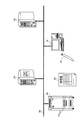
図1は、本実施の形態が適用されるシステムの構成を示したものである。このシステムは、端末装置10と、文書サーバ20と、識別情報サーバ30と、画像形成装置40とがネットワーク90に接続されることにより構成されている。また、このシステムは、印刷文書50と、電子ペン60とを含む。
First, the system configuration in the present embodiment will be described.
FIG. 1 shows a system configuration to which the present embodiment is applied. This system is configured by connecting a
端末装置10は、第1の電子文書の印刷指示を送信したり、電子ペン60からの情報を転送したりする。尚、この端末装置10としては、PC(Personal Computer)が例示される。
文書サーバ20は、電子文書を記憶している。そして、文書サーバ20は、印刷指示があると、文書画像とコード画像とを合成した合成画像の印刷命令を出力する機能を有する。また、第1の電子文書から第2の電子文書を生成する機能も有する。そして、筆記データを第2の電子文書に関連付ける機能も有する。尚、この文書サーバ20は、汎用のサーバコンピュータによって実現することができる。
The
The
識別情報サーバ30は、媒体に付与する識別情報を管理しており、外部からの要求に対して重複がないように識別情報を発行する。尚、この識別情報サーバ30も、汎用のサーバコンピュータによって実現することができる。
画像形成装置40は、媒体に画像を形成する。ここで、画像形成装置40における画像形成方式としては、例えば、電子写真方式を用いることができるが、その他の如何なる方式を用いてもよい。
印刷文書50は、文書画像とコード画像とを合成した合成画像が印刷された媒体である。
電子ペン60は、印刷文書50に文字又は図形を記録する機能を有するペンデバイスである。また、本実施の形態において、電子ペン60は、コード画像から情報を取得し、それを他の装置に送信する機構も有する。
The
The
The
The
次に、図1のシステムの構成要素のうち、文書サーバ20について詳細に説明する。
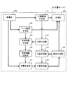
図2は、文書サーバ20の構成の一例を示す図である。
図示するように、文書サーバ20は、受信部20aと、送信部20bと、文書画像生成部21と、コード画像生成部22とを備える。また、文書生成部23と、文書記憶部24と、管理情報生成部25と、管理情報記憶部26とを備える。そして、更に、文書特定部27と、文書取得部28と、筆記付加部29とを備える。
Next, the
FIG. 2 is a diagram illustrating an example of the configuration of the
As illustrated, the
受信部20aは、電子文書の印刷時には、印刷指示と、印刷に関する設定情報(以下、単に「設定情報」という)とをネットワーク90から受信する。そして、印刷指示で指定された第1の電子文書を文書画像生成部21に渡し、設定情報を文書画像生成部21及びコード画像生成部22に渡す。ここで、設定情報とは、例えば、用紙サイズ、向き、余白の大きさ、Nアップ指定(電子文書のNページを用紙の1ページに割り付ける指定)等である。
また、媒体に対して筆記がなされた際には、媒体の識別情報と、媒体上の筆記がなされた位置情報とを受信し、これらの情報を文書特定部27に渡す。
The
In addition, when writing is performed on the medium, the identification information of the medium and the position information on which writing is performed on the medium are received, and these pieces of information are transferred to the
文書画像生成部21は、受信部20aから渡された第1の電子文書を、同じく受信部20aから渡された設定情報に基づいて画像化し、文書画像を生成する。
コード画像生成部22は、受信部20aから渡された設定情報に基づいて識別情報及び位置情報を含むコード画像を生成する。尚、このコード画像生成部22は、媒体に情報を付加するための処理を行う処理手段の一例として捉えることができる。
送信部20bは、電子文書の印刷時には、文書画像とコード画像を画像形成装置40に送信し、これらの画像を合成した合成画像の形成を指示する。
また、媒体に対して筆記がなされた際には、筆記データが反映された第2の電子文書を送信する。
尚、受信部20a、文書画像生成部21、コード画像生成部22、送信部20bは、第1の電子文書を媒体に印刷するための処理を行う処理手段の一例として捉えることができる。
The document
The code
When printing the electronic document, the
In addition, when writing is performed on the medium, the second electronic document reflecting the writing data is transmitted.
The receiving
文書生成部23は、印刷指示で指定された第1の電子文書から、文書画像生成部21が生成した文書画像と同じレイアウトの第2の電子文書を生成する。
文書記憶部24は、文書生成部23が生成した第2の電子文書を記憶する。
管理情報生成部25は、コード画像生成部22がコード画像に埋め込んだ媒体の識別情報と、文書生成部23が生成した第2の電子文書の識別情報とを少なくとも対応付けた管理情報を生成する。
管理情報記憶部26は、管理情報生成部25が生成した管理情報を記憶する。
The
The
The management
The management
文書特定部27は、受信部20aから渡された識別情報に基づいて、筆記データを反映する対象である第2の電子文書を特定する。
文書取得部28は、文書特定部27が特定した第2の電子文書を文書記憶部24から取得する。
筆記付加部29は、文書取得部28が取得した第2の電子文書に対して筆記データを付加する。
The
The
The
尚、これらの機能は、ソフトウェアとハードウェア資源とが協働することにより実現される。具体的には、文書サーバ20の図示しないCPUが、受信部20a、文書画像生成部21、コード画像生成部22、送信部20b、文書生成部23、管理情報生成部25、文書特定部27、文書取得部28、筆記付加部29を実現するプログラムを例えば磁気ディスク装置からメインメモリに読み込んで実行することにより、これらの機能は実現される。また、文書記憶部24、管理情報記憶部26は、例えば磁気ディスク装置を用いて実現することができる。更に、磁気ディスク装置に記憶されるプログラムやデータは、CD等の記録媒体からロードしてもよいし、インターネット等のネットワークを介してダウンロードしてもよい。
These functions are realized by cooperation between software and hardware resources. Specifically, a CPU (not shown) of the
次に、本実施の形態における印刷時の動作について説明する。
まず、ユーザが、端末装置10を操作し、文書サーバ20に格納された電子文書の中から印刷対象の第1の電子文書を指定する。これにより、端末装置10は、第1の電子文書の印刷指示と設定情報とを文書サーバ20に送信し、文書サーバ20の動作が開始する。
Next, the operation at the time of printing in this embodiment will be described.
First, the user operates the
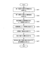
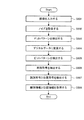
図3は、このときの文書サーバ20の動作を示したフローチャートである。
文書サーバ20では、まず、受信部20aが、印刷指示を受信する(ステップ201)。そして、印刷指示で指定された第1の電子文書を図示しない記憶装置から読み出し、設定情報と共に文書画像生成部21に受け渡す。また、コード画像生成部22に対しても設定情報を受け渡す。
これにより、文書画像生成部21は、第1の電子文書を画像化して文書画像を生成する(ステップ202)。尚、その際、文書画像は、受信部20aから渡された設定情報に従ったレイアウトで生成される。
FIG. 3 is a flowchart showing the operation of the
In the
As a result, the document
一方、コード画像生成部22は、コード画像を生成する(ステップ203)。ここで、コード画像には、上述したように、2種類の情報が埋め込まれる。
1つは、媒体を一意に識別する識別情報である。この識別情報は、識別情報サーバ30(図1参照)から取得することができる。即ち、まず、コード画像生成部22は、識別情報サーバ30に対して識別情報の付与を要求する。これに応じて、識別情報サーバ30が、識別情報を管理するデータベースから未使用の識別情報を取り出し、コード画像生成部22に送信する。ここで、取り出す識別情報の数は、設定情報に応じて決められる。つまり、基本的には、印刷するページ数に印刷部数を乗じて得られる数の識別情報が取り出される。但し、設定情報中に、Nアップ指定等がある場合は、それも考慮される。例えば、電子文書の10ページを2アップ指定で5部印刷する場合は、25(=10÷2×5)個の識別情報が取り出される。
またもう1つは、媒体上の位置を特定するための位置情報である。これは、設定情報に含まれる用紙のサイズや向きに応じて必要となる範囲の座標を表すために用意される情報である。
尚、このコード画像の生成処理の詳細は後述する。
On the other hand, the code
One is identification information for uniquely identifying a medium. This identification information can be acquired from the identification information server 30 (see FIG. 1). That is, first, the code
The other is position information for specifying the position on the medium. This is information prepared to represent the coordinates of a range required depending on the size and orientation of the paper included in the setting information.
Details of the code image generation processing will be described later.
そして、文書サーバ20は、電子文書の文書画像とコード画像とを画像形成装置40に送信し、画像形成を指示する(ステップ204)。
これにより、画像形成装置40では、例えば電子写真方式を用いて合成画像を媒体に形成し、印刷文書50を出力する。尚、その際、文書画像はC(シアン)、M(マゼンタ)、Y(イエロー)のトナーを用いて形成し、コード画像はK(黒)のトナーを用いて形成する。
その後、画像形成装置40は、印刷文書50の出力を完了すると、文書サーバ20に対して印刷完了報告を送信する。これにより、文書サーバ20では、受信部20aが、この印刷完了報告を受信する(ステップ205)。そして、文書画像生成部21に対し、設定情報が反映された文書画像を文書生成部23に送るよう指示する。すると、文書画像生成部21は、文書画像を文書生成部23に送る。そして、文書生成部23は、送られた文書画像と同じレイアウトの第2の電子文書を生成し、文書記憶部24に記憶する(ステップ206)。
Then, the
As a result, the
Thereafter, when the output of the
ここで、第2の電子文書は、第1の電子文書をその内容を変更できない形式に変換することで生成することもできる。このような第2の電子文書の形式としては、富士ゼロックス社の「DocuWorks」における「XDW形式」や、米国アドビシステムズ社の「Acrobat」における「PDF形式」等がある。そして、このように第1の電子文書の内容を変更できない形式で第2の電子文書を生成した場合、例えば、富士ゼロックス社の「DocuWorks」における「アノテーション」の機能を用いて第2の電子文書に筆記データを貼り付けることができる。 Here, the second electronic document can also be generated by converting the first electronic document into a format whose contents cannot be changed. Examples of the format of the second electronic document include “XDW format” in “DocuWorks” by Fuji Xerox Co., “PDF format” in “Acrobat” by Adobe Systems Inc., USA. When the second electronic document is generated in such a format that the content of the first electronic document cannot be changed, for example, the second electronic document is used by using the “annotation” function in “DocuWorks” of Fuji Xerox Co., Ltd. Written data can be pasted on.
次に、管理情報生成部25は、コード画像生成部22から媒体の識別情報(媒体ID)を取得する。一方、文書生成部23からは、第1の電子文書の識別情報(第1文書ID)と、第1の電子文書の中で印刷したページのページ番号と、第2の電子文書の識別情報(第2文書ID)とを取得する。そして、これらの情報を対応付けた管理情報を生成し、管理情報記憶部26に記憶する(ステップ207)。
Next, the management
尚、上記では、コード画像をKのトナーを用いて形成するようにした。これは、Kのトナーが、C、M、Yのトナーよりも赤外光の吸収量が多く、電子ペン60でコード画像を読み取ることができるからである。しかしながら、コード画像は、特殊トナーを用いて形成することも可能である。
ここで、特殊トナーとしては、可視光領域(400nm〜700nm)における最大吸収率が7%以下であり、近赤外領域(800nm〜1000nm)における吸収率が30%以上の不可視トナーが例示される。ここで、「可視」及び「不可視」は、目視により認識できるかどうかとは関係しない。印刷された媒体に形成された画像が可視光領域における特定の波長の吸収に起因する発色性の有無により認識できるかどうかで「可視」と「不可視」とを区別している。また、可視光領域における特定の波長の吸収に起因する発色性が若干あるが、人間の目で認識し難いものも「不可視」に含める。
また、この不可視トナーは、画像の機械読取りのために必要な近赤外光吸収能力を高めるために、平均分散径が100nm〜600nmの範囲のものが望ましい。
In the above, the code image is formed using K toner. This is because the K toner has more infrared light absorption than the C, M, and Y toners, and the code image can be read by the
Here, as the special toner, an invisible toner having a maximum absorption rate of 7% or less in the visible light region (400 nm to 700 nm) and an absorption rate of 30% or more in the near infrared region (800 nm to 1000 nm) is exemplified. . Here, “visible” and “invisible” are not related to whether they can be recognized visually. “Visible” and “invisible” are distinguished depending on whether or not an image formed on a printed medium can be recognized by the presence or absence of color development due to absorption of a specific wavelength in the visible light region. Further, “invisible” includes those that have some color developability due to absorption of a specific wavelength in the visible light region but are difficult to recognize with human eyes.
The invisible toner preferably has an average dispersion diameter in the range of 100 nm to 600 nm in order to increase the near infrared light absorption capability necessary for machine reading of an image.
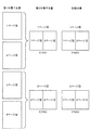
次に、図3の処理により生成される第2の電子文書及び印刷文書50について説明する。
図4は、印刷対象の電子文書である第1の電子文書と、筆記データを反映させるための電子文書である第2の電子文書と、第1の電子文書が印刷された印刷文書50とを対比して示した図である。
ここでは、第1の電子文書をA4サイズとし、その4ページをA4サイズの用紙に2アップ指定で出力する場合を例示している。
Next, the second electronic document and the
FIG. 4 shows a first electronic document that is an electronic document to be printed, a second electronic document that is an electronic document for reflecting writing data, and a printed
In this example, the first electronic document is set to A4 size, and four pages of the first electronic document are output to A4 size paper with 2-up designation.
この場合、図3のフローチャートに従って処理すると、次のようになる。
即ち、ステップ201〜204の処理により、第1の電子文書の1ページ目及び2ページ目の画像が媒体「P1001」に印刷され、印刷文書50の1ページ目となる。また、第1の電子文書の3ページ目及び4ページ目の画像が媒体「P1002」に印刷され、印刷文書50の2ページ目となる。
また、ステップ206の処理により、第1の電子文書の1ページ目及び2ページ目を含む第2の電子文書「C1001」と、第1の電子文書の3ページ目及び4ページ目を含む第2の電子文書「C1002」とが生成される。
In this case, processing according to the flowchart of FIG. 3 is as follows.
In other words, the first and second page images of the first electronic document are printed on the medium “P1001” by the processing in steps 201 to 204, and become the first page of the
In addition, by the processing in step 206, the second electronic document “C1001” including the first page and the second page of the first electronic document, and the second page including the third page and the fourth page of the first electronic document are displayed. The electronic document “C1002” is generated.
尚、このとき、第2の電子文書に対しては、印刷文書50上の座標系と同じ向きの座標系が暗黙に設定されているものとする。つまり、図4に対比して示したように、第2の電子文書と印刷文書50の見え方が同じになるように向きを揃えた状態で、その両方に対し、例えば、左上点を原点とし、右方向をX軸とし、下方向をY軸とする座標系が設定される。これにより、印刷文書50上でポイントされた座標がそのまま第2の電子文書上の座標となるのである。
At this time, it is assumed that a coordinate system having the same orientation as the coordinate system on the
また、文書サーバ20内の管理情報記憶部26が記憶する管理情報の内容についても具体的に説明しておく。
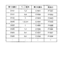
図5に、この管理情報の一例を示す。
図示するように、この管理情報は、第1文書IDと、ページ番号と、第2文書IDと、媒体IDとを対応付けたものになっている。
The contents of the management information stored in the management
FIG. 5 shows an example of this management information.
As shown in the figure, the management information is a correspondence between the first document ID, the page number, the second document ID, and the medium ID.
第1文書IDは、第1の電子文書を一意に識別するための識別情報である。この第1文書IDとしては、電子文書の格納場所の情報(アドレス情報)を採用してもよいし、アドレス情報とは関係のない番号等を採用してもよい。但し、後者の場合は、その番号等に基づいて第1の電子文書を取得するための情報を別途管理しておく必要がある。
ページ番号は、第1の電子文書のページを示す番号である。
第2文書IDは、第2の電子文書を一意に識別するための識別情報である。この第2文書IDとしては、電子文書の格納場所の情報(アドレス情報)を採用してもよいし、アドレス情報とは関係のない番号等を採用してもよい。但し、後者の場合は、その番号等に基づいて第2の電子文書を取得するための情報を別途管理しておく必要がある。
媒体IDは、第1の電子文書を印刷した媒体を一意に識別するための識別情報である。
The first document ID is identification information for uniquely identifying the first electronic document. As the first document ID, information on the storage location of the electronic document (address information) may be employed, or a number unrelated to the address information may be employed. However, in the latter case, it is necessary to separately manage information for acquiring the first electronic document based on the number or the like.
The page number is a number indicating the page of the first electronic document.
The second document ID is identification information for uniquely identifying the second electronic document. As the second document ID, information on the storage location of the electronic document (address information) may be employed, or a number unrelated to the address information may be employed. However, in the latter case, it is necessary to separately manage information for acquiring the second electronic document based on the number or the like.
The medium ID is identification information for uniquely identifying the medium on which the first electronic document is printed.
例えば、図5の第1の電子文書「D101」に関する管理情報を参照すると、その1ページ目及び2ページ目が媒体「P1001」に印刷され、その3ページ目及び4ページ目が媒体「P1002」に印刷されていることが分かる。また、その1ページ目及び2ページ目を含む第2の電子文書「C1001」と、その3ページ目及び4ページ目を含む第2の電子文書「C1002」とが生成されていることも分かる。つまり、図4に示したような状態を第1文書ID、ページ番号、第2文書ID、媒体IDを用いて管理しているのである。
尚、第1文書ID及びページ番号は、媒体IDに基づいて第2の電子文書を特定するだけであれば、この管理情報に必ずしも含める必要はない。つまり、例えば、第1文書IDとページ番号と第2文書IDとの対応関係を別途管理する構成を採用してもよい。
For example, referring to the management information related to the first electronic document “D101” in FIG. 5, the first and second pages are printed on the medium “P1001”, and the third and fourth pages are printed on the medium “P1002”. It can be seen that it is printed on. It can also be seen that the second electronic document “C1001” including the first and second pages and the second electronic document “C1002” including the third and fourth pages are generated. That is, the state as shown in FIG. 4 is managed using the first document ID, page number, second document ID, and medium ID.
Note that the first document ID and the page number do not necessarily need to be included in the management information if the second electronic document is only specified based on the medium ID. That is, for example, a configuration in which the correspondence relationship between the first document ID, the page number, and the second document ID is separately managed may be employed.
次に、本実施の形態で生成されるコード画像の元となるコードパターンについて説明する。
図6は、コードパターンについて説明するための図である。
まず、コードパターンを構成するビットパターンについて説明する。
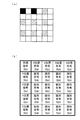
図6(a)に、ビットパターンの配置の一例を示す。
ビットパターンとは、情報埋め込みの最小単位である。ここでは、図6(a)に示すように、9箇所の中から選択した2箇所にビットを配置する。図では、黒の四角が、ビットが配置された位置を示し、斜線の四角が、ビットが配置されていない位置を示している。9箇所の中から2箇所を選択する組み合わせは、36(=9C2)通りある。従って、このような配置方法により、36通り(約5.2ビット)の情報を表現することができる。
Next, the code pattern that is the basis of the code image generated in the present embodiment will be described.
FIG. 6 is a diagram for explaining a code pattern.
First, the bit pattern constituting the code pattern will be described.
FIG. 6A shows an example of bit pattern arrangement.
A bit pattern is the minimum unit of information embedding. Here, as shown in FIG. 6A, bits are arranged at two locations selected from nine locations. In the figure, black squares indicate positions where bits are arranged, and hatched squares indicate positions where bits are not arranged. There are 36 (= 9 C 2 ) combinations for selecting 2 locations out of 9 locations. Therefore, 36 kinds (about 5.2 bits) of information can be expressed by such an arrangement method.
ところで、図6(a)に示した最小の四角は、600dpiにおける2ドット×2ドットの大きさを有している。600dpiにおける1ドットの大きさは0.0423mmなので、この最小の四角の一辺は、84.6μm(=0.0423mm×2)である。コードパターンを構成するドットは、大きくなればなるほど目に付きやすくなるため、できるだけ小さいほうが好ましい。ところが、あまり小さくすると、プリンタで印刷できなくなってしまう。そこで、ドットの大きさとして、50μmより大きく100μmより小さい上記の値を採用している。これにより、プリンタで印刷可能な最適な大きさのドットを形成することができる。つまり、84.6μm×84.6μmが、プリンタで安定的に形成可能な最小の大きさなのである。
尚、ドットをこのような大きさにすることで、1つのビットパターンの一辺は、約0.5mm(=0.0423mm×2×6)となる。
By the way, the minimum square shown in FIG. 6A has a size of 2 dots × 2 dots at 600 dpi. Since the size of one dot at 600 dpi is 0.0423 mm, one side of this minimum square is 84.6 μm (= 0.0423 mm × 2). The larger the dots that make up the code pattern, the more likely it is to be noticeable. However, if it is too small, printing with a printer becomes impossible. Therefore, the above value is adopted as the dot size, which is larger than 50 μm and smaller than 100 μm. Thereby, it is possible to form dots of an optimum size that can be printed by the printer. That is, 84.6 μm × 84.6 μm is the minimum size that can be stably formed by the printer.
In addition, by setting the dot to such a size, one side of one bit pattern becomes about 0.5 mm (= 0.0423 mm × 2 × 6).
また、このようなビットパターンから構成されるコードパターンについて説明する。
図6(b)に、コードパターンの配置の一例を示す。
ここで、図6(b)に示した最小の四角が、図6(a)に示したビットパターンに相当する。尚、図6(a)では、1つのビットパターンで36通りの情報を表現できるものとして説明したが、このコードパターンにおいて、1つのビットパターンは、同期符号を除き、32通り(5ビット)の情報を表現するものとする。
A code pattern composed of such bit patterns will be described.
FIG. 6B shows an example of the arrangement of code patterns.
Here, the minimum square shown in FIG. 6B corresponds to the bit pattern shown in FIG. In FIG. 6 (a), it has been described that 36 kinds of information can be expressed by one bit pattern. However, in this code pattern, one bit pattern has 32 kinds (5 bits) except for a synchronous code. It shall represent information.
そして、識別情報を符号化した識別符号は、16(=4×4)個のビットパターンを使用して埋め込まれる。また、X方向の位置情報を符号化したX位置符号と、Y方向の位置情報を符号化したY位置符号とは、それぞれ、4個のビットパターンを使用して埋め込まれる。更に、左上角部に、コードパターンの位置と回転を検出するための同期符号が、1つのビットパターンを使用して埋め込まれる。
尚、1つのコードパターンの大きさは、ビットパターンの5個分の幅に等しいため、約2.5mmとなる。本実施の形態では、このように生成したコードパターンを画像化したコード画像を、用紙全面に配置する。
The identification code obtained by encoding the identification information is embedded using 16 (= 4 × 4) bit patterns. Also, the X position code obtained by encoding the position information in the X direction and the Y position code obtained by encoding the position information in the Y direction are each embedded using four bit patterns. Further, a synchronization code for detecting the position and rotation of the code pattern is embedded in the upper left corner using one bit pattern.
Note that the size of one code pattern is approximately 2.5 mm because it is equal to the width of five bit patterns. In the present embodiment, a code image obtained by imaging the code pattern generated in this way is arranged on the entire sheet surface.
次いで、識別情報及び位置情報を符号化し、符号化された情報からコード画像を生成する処理について説明する。尚、この処理は、コード画像生成部22(図2参照)がステップ203(図3参照)で実行する。
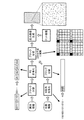
図7は、このような符号化及び画像生成の処理について説明するための図である。
まず、識別情報の符号化について説明する。
識別情報の符号化には、ブロック符号化方式のRS(リードソロモン)符号が使用される。図6で説明した通り、本実施の形態では、5ビットの情報を表現できるビットパターンを用いて情報を埋め込む。従って、情報の誤りも5ビット単位で発生するため、ブロック符号化方式で符号化効率が良いRS符号を使用している。但し、符号化方式はRS符号に限定するものでなく、その他の符号化方式、例えば、BCH符号等を使用することもできる。
Next, processing for encoding identification information and position information and generating a code image from the encoded information will be described. This process is executed by the code image generation unit 22 (see FIG. 2) in step 203 (see FIG. 3).
FIG. 7 is a diagram for explaining such encoding and image generation processing.
First, encoding of identification information will be described.
For encoding the identification information, an RS (Reed Solomon) code of a block encoding method is used. As described with reference to FIG. 6, in this embodiment, information is embedded using a bit pattern that can represent 5-bit information. Accordingly, since an information error also occurs in units of 5 bits, an RS code having good coding efficiency is used in the block coding method. However, the encoding method is not limited to the RS code, and other encoding methods such as a BCH code can also be used.
上述したように、本実施の形態では、5ビットの情報量を持つビットパターンを用いて情報を埋め込む。従って、RS符号のブロック長を5ビットとする必要がある。そのため、識別情報を5ビットずつに区切り、ブロック化する。図7では、識別情報「0011101101001…」から、第1のブロック「00111」と、第2のブロック「01101」とが切り出されている。
そして、ブロック化された識別情報に対し、RS符号化処理を行う。図7では、「blk1」、「blk2」、「blk3」、「blk4」、…というようにブロック化した後、RS符号化が行われる。
As described above, in the present embodiment, information is embedded using a bit pattern having an information amount of 5 bits. Therefore, the block length of the RS code needs to be 5 bits. For this reason, the identification information is divided into blocks of 5 bits. In FIG. 7, the first block “00111” and the second block “01101” are cut out from the identification information “0011101101001...”.
Then, RS coding processing is performed on the identification information that has been blocked. In FIG. 7, after the blocks such as “blk1”, “blk2”, “blk3”, “blk4”,..., RS encoding is performed.
ところで、本実施の形態において、識別情報は、16(=4×4)個のブロックに分けられる。そこで、RS符号における符号ブロック数を16とすることができる。また、情報ブロック数は、誤りの発生状況に応じて設計することができる。例えば、情報ブロック数を8とすれば、RS(16,8)符号となる。この符号は、符号化された情報に4ブロック(=(16−8)÷2)の誤りが発生しても、それを補正することができる。また、誤りの位置を特定できれば、訂正能力を更に向上することができる。尚、この場合、情報ブロックに格納される情報量は、40ビット(=5ビット×8ブロック)である。従って、約1兆種類の識別情報が表現可能である。 By the way, in this embodiment, the identification information is divided into 16 (= 4 × 4) blocks. Therefore, the number of code blocks in the RS code can be 16. Further, the number of information blocks can be designed according to an error occurrence state. For example, if the number of information blocks is 8, RS (16, 8) code is obtained. This code can correct even if an error of 4 blocks (= (16−8) / 2) occurs in the encoded information. Moreover, if the position of the error can be specified, the correction capability can be further improved. In this case, the amount of information stored in the information block is 40 bits (= 5 bits × 8 blocks). Therefore, about 1 trillion kinds of identification information can be expressed.
次に、位置情報の符号化について説明する。
位置情報の符号化には、擬似乱数系列の一種であるM系列符号が使用される。ここで、M系列とは、K段の線形シフトレジスタで発生できる最大周期の系列であり、2K−1の系列長をもつ。このM系列から取り出した任意の連続したKビットは、同じM系列中の他の位置に現れない性質を持つ。そこで、この性質を利用することにより、位置情報を符号化することができる。
Next, encoding of position information will be described.
For encoding the position information, an M-sequence code, which is a kind of pseudo-random sequence, is used. Here, the M sequence is a sequence of the maximum period that can be generated by a K-stage linear shift register, and has a sequence length of 2 K −1. Arbitrary consecutive K bits extracted from the M sequence have a property that they do not appear at other positions in the same M sequence. Therefore, the position information can be encoded by using this property.
ところで、本実施の形態では、符号化すべき位置情報の長さから、必要なM系列の次数を求め、M系列を生成している。しかしながら、符号化する位置情報の長さが予め分かっている場合は、M系列を毎回生成する必要はない。即ち、固定のM系列を予め生成しておき、それをメモリ等に格納しておけばよい。
例えば、系列長8191のM系列(K=13)を使用したとする。
この場合、位置情報も5ビット単位で埋め込むため、系列長8191のM系列から5ビットずつ取り出してブロック化する。図7では、M系列「11010011011010…」が、5ビットずつブロック化されている。
By the way, in the present embodiment, a necessary M-sequence order is obtained from the length of position information to be encoded, and an M-sequence is generated. However, if the length of the position information to be encoded is known in advance, it is not necessary to generate the M sequence each time. That is, a fixed M sequence may be generated in advance and stored in a memory or the like.
For example, it is assumed that an M sequence (K = 13) having a sequence length of 8191 is used.
In this case, since the position information is also embedded in units of 5 bits, 5 bits are extracted from the M series having a sequence length of 8191 and blocked. In FIG. 7, the M sequence “11010011011010...” Is divided into blocks of 5 bits.
このように、本実施の形態では、位置情報と識別情報とで、異なる符号化方式を用いている。これは、識別情報の検出能力を、位置情報の検出能力よりも高くなるように設定する必要があるからである。つまり、位置情報は、紙面の位置を取得するための情報なので、ノイズ等によって復号できない部分があっても、その部分が欠損するだけで他の部分には影響しない。これに対し、識別情報は、復号に失敗すると、筆記情報を反映する対象を検出できなくなるからである。更に、このような構成とすることによって、位置情報と識別情報を復号する際の画像読取範囲を最小化できる。即ち、位置情報にRS符号等の境界を有する符号化方式を使用すると、それを復号する際には境界間の符号を読み取る必要があるため、画像を読み取る範囲は図6(b)に示した領域の2倍の領域とする必要がある。しかし、M系列を使用することで、図6(b)に示した領域と同じ大きさの領域を読み取ればよい構成にできる。これは、M系列の性質上、M系列の任意の部分系列から位置情報を復号できるからである。即ち、識別情報と位置情報を復号する際には、図6(b)に示した大きさの領域を読み取る必要があるが、その読み取る位置は、図6(b)に示した境界と一致させる必要はない。位置情報は、M系列の任意位置の部分系列から復号できる。識別情報は、同じ情報が用紙全面に配置されるため、図6(b)に図示した境界から読取位置がずれても、読み取られた情報の断片を再配置することで元の情報を復元することができる。 Thus, in the present embodiment, different encoding methods are used for position information and identification information. This is because it is necessary to set the detection capability of identification information to be higher than the detection capability of position information. That is, since the position information is information for acquiring the position of the paper surface, even if there is a part that cannot be decoded due to noise or the like, the part is lost and does not affect the other part. On the other hand, if the identification information fails to be decoded, it is impossible to detect a target reflecting the writing information. Further, with such a configuration, it is possible to minimize the image reading range when decoding the position information and the identification information. That is, if an encoding method having a boundary such as an RS code is used for position information, it is necessary to read the code between the boundaries when decoding it, so the image reading range is shown in FIG. The area needs to be twice as large as the area. However, by using the M series, it is possible to have a configuration in which an area having the same size as the area shown in FIG. This is because the position information can be decoded from an arbitrary partial sequence of the M sequence due to the nature of the M sequence. That is, when decoding the identification information and the position information, it is necessary to read the area having the size shown in FIG. 6B, but the read position matches the boundary shown in FIG. 6B. There is no need. The position information can be decoded from a partial series at an arbitrary position of the M series. Since the same information is arranged on the entire surface of the sheet, the original information is restored by rearranging the pieces of read information even if the reading position is shifted from the boundary shown in FIG. 6B. be able to.
以上のように、識別情報がブロック分割された後、RS符号により符号化され、また、位置情報がM系列により符号化された後、ブロック分割されると、図示するように、ブロックが合成される。即ち、これらのブロックは、図示するようなフォーマットで2次元平面に展開される。図7に示したフォーマットは、図6(b)に示したフォーマットに対応している。即ち、黒の四角が同期符号を意味している。また、横方向に配置された「1」、「2」、「3」、「4」、…がX位置符号を、縦方向に配置された「1」、「2」、「3」、「4」、…がY位置符号を、それぞれ意味している。位置符号は、媒体の位置が異なれば異なる情報が配置されるので、座標位置に対応する数字で示しているのである。一方、グレーの四角が識別符号を意味している。識別符号は、媒体の位置が異なっても同じ情報が配置されるので、全て同じマークで示しているのである。 As described above, after the identification information is divided into blocks, it is encoded with an RS code, and when the position information is encoded with an M sequence and then divided into blocks, a block is synthesized as shown in the figure. The That is, these blocks are developed on a two-dimensional plane in the format shown in the figure. The format shown in FIG. 7 corresponds to the format shown in FIG. That is, a black square means a synchronization code. Further, “1”, “2”, “3”, “4”,... Arranged in the horizontal direction represent X position codes, and “1”, “2”, “3”, “ 4 ”,... Mean Y position codes. The position code is indicated by a number corresponding to the coordinate position because different information is arranged if the position of the medium is different. On the other hand, a gray square means an identification code. Since the same information is arranged even if the position of the medium is different, the identification codes are all indicated by the same mark.
ところで、図からも分かる通り、2つの同期符号の間には、4個のビットパターンがある。従って、20(=5×4)ビットのM系列の部分系列を配置することができる。20ビットの部分系列から13ビットの部分系列を取り出せば、その13ビットが全体(8191)の中のどの部分の部分系列なのかを特定することができる。このように、20ビットのうち13ビットを位置の特定に使用した場合、取り出した13ビットの誤りの検出又は訂正を、残りの7ビットを使用して行うことができる。即ち、M系列を生成した時と同じ生成多項式を使用して、20ビットの整合性を確認することで、誤りの検出と訂正が可能となるのである。
その後、各ブロックにおけるビットパターンが、ドット画像を参照することにより画像化される。そして、図7の最右に示すようなドットで情報を表す出力画像が生成される。
By the way, as can be seen from the figure, there are four bit patterns between two synchronization codes. Therefore, 20 (= 5 × 4) -bit M-sequence partial sequences can be arranged. If a 13-bit partial sequence is extracted from the 20-bit partial sequence, it is possible to specify which partial sequence in the whole (8191) the 13 bits are. As described above, when 13 bits out of 20 bits are used for specifying the position, it is possible to detect or correct the extracted 13-bit error using the remaining 7 bits. That is, it is possible to detect and correct an error by confirming the 20-bit consistency by using the same generator polynomial as when the M sequence was generated.
Thereafter, the bit pattern in each block is imaged by referring to the dot image. Then, an output image representing information with dots as shown on the rightmost side of FIG. 7 is generated.
次いで、本実施の形態において筆記データを電子文書に反映させる際の動作について説明する。但し、以下の説明において、筆記データは、電子文書に直接付加されるものとする。
まず、印刷文書50に対する筆記を読み取るのに用いられる電子ペン60について説明する。
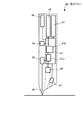
図8は、電子ペン60の機構を示した図である。
図示するように、電子ペン60は、ペン全体の動作を制御する制御回路61を備える。また、制御回路61は、入力画像から検出したコード画像を処理する画像処理部61aと、そこでの処理結果から識別情報及び位置情報を抽出するデータ処理部61bとを含む。
そして、制御回路61には、電子ペン60による筆記動作をペンチップ69に加わる圧力によって検出する圧力センサ62が接続されている。また、媒体上に赤外光を照射する赤外LED63と、画像を入力する赤外CMOS64も接続されている。更に、識別情報及び位置情報を記憶するための情報メモリ65と、外部装置と通信するための通信回路66と、ペンを駆動するためのバッテリ67と、ペンの識別情報(ペンID)を記憶するペンIDメモリ68も接続されている。
Next, an operation when reflecting handwritten data in an electronic document in the present embodiment will be described. However, in the following description, handwritten data is assumed to be added directly to the electronic document.
First, the
FIG. 8 is a diagram illustrating the mechanism of the
As illustrated, the
The
ここで、この電子ペン60の動作の概略を説明する。
電子ペン60による筆記が行われると、ペンチップ69に接続された圧力センサ62が、筆記動作を検出する。これにより、赤外LED63が点灯し、赤外CMOS64がCMOSセンサによって媒体上の画像を撮像する。
尚、赤外LED63は、消費電力を抑制するために、CMOSセンサのシャッタタイミングに同期させてパルス点灯する。
また、赤外CMOS64は、撮像した画像を同時に転送できるグローバルシャッタ方式のCMOSセンサを使用する。そして、赤外領域に感度があるCMOSセンサを使用する。また、外乱の影響を低減するために、CMOSセンサ全面に可視光カットフィルタを配置している。CMOSセンサは、70fps〜100fps(frame per second)程度の周期で、画像を撮像する。尚、撮像素子はCMOSセンサに限定するものではなく、CCD等、他の撮像素子を使用してもよい。
Here, an outline of the operation of the
When writing with the
The
The
このように撮像した画像が制御回路61に入力されると、制御回路61は、撮像した画像からコード画像を取得する。そして、それを復号し、コード画像に埋め込まれている識別情報及び位置情報を取得する。
以下、このときの制御回路61の動作について説明する。
図9は、制御回路61の動作を示したフローチャートである。
まず、画像処理部61aは、画像を入力する(ステップ601)。そして、画像に含まれるノイズを除去するための処理を行う(ステップ602)。ここで、ノイズとしては、CMOS感度のばらつきや電子回路により発生するノイズ等がある。ノイズを除去するために如何なる処理を行うかは、電子ペン60の撮像系の特性に応じて決定すべきである。例えば、ぼかし処理やアンシャープマスキング等の先鋭化処理を適用することができる。
When the captured image is input to the
Hereinafter, the operation of the
FIG. 9 is a flowchart showing the operation of the
First, the
次に、画像処理部61aは、画像からドットパターン(ドット画像の位置)を検出する(ステップ603)。例えば、2値化処理によりドットパターン部と背景部とを切り分け、2値化された個々の画像位置からドットパターンを検出することができる。2値化画像にノイズ成分が多数含まれる場合は、例えば、2値化画像の面積や形状によりドットパターンの判定を行うフィルタ処理を組み合わせる必要がある。
また、画像処理部61aは、検出したドットパターンを2次元配列上のデジタルデータに変換する(ステップ604)。例えば、2次元配列上で、ドットがある位置を「1」、ドットがない位置を「0」というように変換する。そして、この2次元配列上のデジタルデータは、画像処理部61aからデータ処理部61bへと受け渡される。
Next, the
In addition, the
次いで、データ処理部61bは、受け渡されたデジタルデータから、図6(a)に示した2つのドットの組み合わせからなるビットパターンを検出する(ステップ605)。例えば、ビットパターンに対応するブロックの境界位置を2次元配列上で動かし、ブロック内に含まれるドットの数が2つになるような境界位置を検出することにより、ビットパターンを検出することができる。
このようにしてビットパターンが検出されると、データ処理部61bは、ビットパターンの種類を参照することにより、同期符号を検出する(ステップ606)。そして、同期符号からの位置関係に基づいて、識別符号及び位置符号を検出する(ステップ607)。
その後、データ処理部61bは、識別符号を復号して識別情報を取得し、位置符号を復号して位置情報を取得する(ステップ608)。識別符号については、RS復号処理を施すことで識別情報を得る。一方、位置符号については、読み出した部分系列の位置を、画像生成時に使用したM系列と比較することで、位置情報を得る。
Next, the
When the bit pattern is detected in this way, the
Thereafter, the
その後、電子ペン60は、このように取得した識別情報(媒体ID)及び位置情報(座標)を端末装置10に送信する。これにより、端末装置10は、媒体ID及び座標を文書サーバ20に送信し、文書サーバ20の動作が開始する。
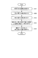
図10は、このときの文書サーバ20の動作を示したフローチャートである。
文書サーバ20では、まず、受信部20aが、媒体ID及び座標を受信する(ステップ221)。そして、これらの情報を文書特定部27に受け渡す。すると、文書特定部27は、管理情報記憶部26に記憶された管理情報を参照し、媒体IDに基づいて第2文書IDを取得する(ステップ222)。即ち、筆記がなされた媒体に対応する第2の電子文書を特定する。そして、文書特定部27は、この第2文書IDと座標とを文書取得部28に渡す。これにより、文書取得部28は、この第2文書IDで特定される第2の電子文書を文書記憶部24から読み出す(ステップ223)。そして、文書取得部28は、この読み出した第2の電子文書と座標とを筆記付加部29に渡す。
Thereafter, the
FIG. 10 is a flowchart showing the operation of the
In the
これにより、筆記付加部29は、第2の電子文書に対して、座標によって構成される筆記データを付加し、文書記憶部24に書き戻す(ステップ224)。
そして、筆記付加部29は、この筆記データが付加された第2の電子文書を送信部20bに渡し、送信部20bがこれを例えば端末装置10に送信する(ステップ225)。
尚、筆記データを電子文書に反映するタイミングとしては、種々のものが考えられる。例えば、電子ペン60が用紙を離れた時、電子ペン60による筆記が別のページに移った時、電子ペン60による筆記が最後になされてから一定時間が経過した時等である。
As a result, the
Then, the
Various timings for reflecting the writing data in the electronic document are conceivable. For example, when the
次に、図10のフローチャートに示した処理を具体例によって説明する。
ここでは、説明を簡単にするために,A4用紙の短手方向の幅を210、長手方向の幅を296とする。この状態で、図4に示した媒体「P1002」における点(222,105)がポイントされたものとする。
その場合、図10のフローチャートに従って処理すると,次のようになる。
まず、ステップ221で、受信部20aが、媒体ID「P1002」及び座標(222,105)を受信する。
Next, the process shown in the flowchart of FIG. 10 will be described using a specific example.
Here, in order to simplify the description, it is assumed that the width of the A4 sheet in the short direction is 210 and the width in the long direction is 296. In this state, it is assumed that the point (222, 105) in the medium “P1002” shown in FIG.
In that case, processing according to the flowchart of FIG. 10 is as follows.
First, in step 221, the receiving
次に、ステップ222で、文書特定部27が、筆記データを反映させる対象として第2の電子文書「C1002」を特定し、ステップ223で、文書取得部28が、これを読み出す。
そして、ステップ224で、筆記付加部29が、第2の電子文書「C1002」における点(222,105)の位置に筆記データを付加し、ステップ225で、送信部20bが、筆記データが付加された第2の電子文書「C1002」を例えば端末装置10に送信する。
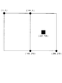
以上の処理により、第2の電子文書は、図11に示すような状態になる。ここでは、黒い四角形が筆記データを付加した箇所を示している。
Next, in step 222, the
In step 224, the
With the above processing, the second electronic document is in a state as shown in FIG. Here, a black square indicates a portion to which writing data is added.
最後に、本実施の形態における文書サーバ20のハードウェア構成について説明しておく。
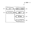
図12は、文書サーバ20のハードウェア構成を示した図である。
図示するように、文書サーバ20は、演算手段であるCPU(Central Processing Unit)101と、記憶手段であるメインメモリ102及び磁気ディスク装置(HDD:Hard Disk Drive)103とを備える。ここで、CPU101は、OS(Operating System)やアプリケーション等の各種ソフトウェアを実行し、上述した各機能を実現する。また、メインメモリ102は、各種ソフトウェアやその実行に用いるデータ等を記憶する記憶領域であり、磁気ディスク装置103は、各種ソフトウェアに対する入力データや各種ソフトウェアからの出力データ等を記憶する記憶領域である。
更に、文書サーバ20は、外部との通信を行うための通信I/F104と、ビデオメモリやディスプレイ等からなる表示機構105と、キーボードやマウス等の入力デバイス106とを備える。
Finally, the hardware configuration of the
FIG. 12 is a diagram illustrating a hardware configuration of the
As shown in the figure, the
Furthermore, the
以上により、本実施の形態の説明を終了する。
尚、本実施の形態では、印刷対象の第1の電子文書から、筆記データを反映させるための第2の電子文書を、印刷の際に生成するという構成を採用した。これに対し、第2の電子文書を印刷の際には生成せずに、筆記がなされた際に生成するという構成も考えられる。
しかしながら、本実施の形態では、次のような理由により、前者の構成を採用し、後者の構成は採用しなかった。
This is the end of the description of the present embodiment.
In the present embodiment, a configuration is adopted in which a second electronic document for reflecting written data is generated from the first electronic document to be printed at the time of printing. On the other hand, a configuration in which the second electronic document is not generated at the time of printing but is generated at the time of writing is also conceivable.
However, in the present embodiment, the former configuration is employed for the following reason, and the latter configuration is not employed.
即ち、第1の電子文書をそのレイアウトを変更して印刷すると、印刷文書50上の位置を電子文書上の位置に変換するために、レイアウトに関する設定情報を参照する必要がある。しかしながら、印刷時における設定情報は多岐に渡るため、設定情報を一旦保存し、それを用いて印刷文書50上の位置を電子文書上の位置に変換する、といった処理は、非常に煩雑なものとなってしまう。その結果、ユーザが印刷文書50に書き込んでからその書き込んだ内容がPC上のディスプレイに表示されるまでのタイムラグが大きくなってしまうからである。例えば、2アップ指定で印刷された用紙上で、電子文書の1ページ目に対応する領域と2ページ目に対応する領域とに交互に記入していくような場合には、ページの切り替え処理が何度も発生してしまい、特に処理に時間を要する。
更に、ペンの分解能を高めて、より精細な手書き入力を実施しようとすると、限られたハードウェア資源では、変換に時間がかかってしまう。従って、読み取ったデータを大量に保存しておく必要があるということも理由の1つである。
That is, when the first electronic document is printed with its layout changed, it is necessary to refer to the setting information regarding the layout in order to convert the position on the
Furthermore, if the resolution of the pen is increased and finer handwriting input is to be performed, conversion takes time with limited hardware resources. Therefore, one of the reasons is that it is necessary to store a large amount of read data.
但し、このような筆記時の処理速度の向上という目的からすれば、第1の電子文書から第2の電子文書を生成するタイミングは、第1の電子文書を印刷する際である必要はない。第2の電子文書は、ユーザによる筆記がなされた際に筆記データを反映できるように予め作成されていればよい。或いは、媒体に対してユーザにより筆記がなされるまでの所定の時点で第2の電子文書を作成しておけばよい。尚、通常、印刷文書50の出力後、どの時期に筆記がなされるかを、システムは知り得ない。従って、その印刷文書50に対して筆記がなされる前であること、例えば、これから筆記を開始することを示す信号をシステムに送信し、その信号を受信した際に第2の電子文書を生成するようにしてもよい。
However, for the purpose of improving the processing speed at the time of writing, the timing for generating the second electronic document from the first electronic document does not need to be when the first electronic document is printed. The second electronic document only needs to be created in advance so that the written data can be reflected when written by the user. Alternatively, the second electronic document may be created at a predetermined time until the user writes on the medium. Normally, the system cannot know when the writing is made after the
また、本実施の形態では、第1の電子文書を印刷した際と同じレイアウトで第2の電子文書を生成するようにした。しかしながら、全く同じレイアウトである必要はない。第1の電子文書を印刷した際のレイアウトと第2の電子文書のレイアウトに若干の違いがあったとしても、ユーザが媒体に筆記した際に、その違いに起因して複雑な変換処理が必要とならなければよい。例えば、拡大縮小程度の変換処理が必要になる構成であってもよい。 Further, in the present embodiment, the second electronic document is generated with the same layout as when the first electronic document is printed. However, it is not necessary to have the exact same layout. Even if there is a slight difference between the layout when the first electronic document is printed and the layout of the second electronic document, complicated conversion processing is required due to the difference when the user writes on the medium. If not, it ’s good. For example, the configuration may require a conversion process that is about the enlargement / reduction.
更に、本実施の形態では、媒体IDをコード画像に含めて媒体に印刷し、媒体IDと第2文書IDとの対応関係を管理情報にて管理するようにすることで、媒体IDから第2の電子文書を特定できるようにした。しかしながら、第2文書IDを直接コード画像に含めるようにしてもよい。この場合は、管理情報を参照することなく、コード画像から取得した第2文書IDに基づいて第2の電子文書に直接アクセスする構成となる。 Furthermore, in the present embodiment, the medium ID is included in the code image, printed on the medium, and the correspondence between the medium ID and the second document ID is managed by the management information, so that the second from the medium ID. It became possible to identify the electronic document. However, the second document ID may be directly included in the code image. In this case, the second electronic document is directly accessed based on the second document ID acquired from the code image without referring to the management information.
更にまた、本実施の形態では、第2の電子文書に筆記データを直接付加することを前提として説明してきた。しかしながら、第2の電子文書の属性情報(リンク情報等)と筆記データとをデータベース上で関係付けておくような構成としてもよい。或いは、第2の電子文書の属性情報と筆記データとをファイルとして一体に保持するような構成としてもよい。即ち、筆記データと第2の電子文書とを関連付けておき、必要に応じて第2の電子文書と筆記データとを重畳して表示できるような手法であれば、如何なる手法でも用いることができる。 Furthermore, the present embodiment has been described on the assumption that handwritten data is directly added to the second electronic document. However, the configuration may be such that the attribute information (link information or the like) of the second electronic document is associated with the handwritten data on the database. Or it is good also as a structure which hold | maintains integrally the attribute information and writing data of a 2nd electronic document as a file. That is, any technique can be used as long as it is a technique in which the writing data and the second electronic document are associated with each other and the second electronic document and the writing data can be superimposed and displayed as necessary.
ところで、上記説明では、文書画像やコード画像の生成、第1の電子文書からの第2の電子文書の生成、媒体IDと第2文書IDとを対応付けた管理情報の記憶を全て文書サーバ20にて行ったが、必ずしもかかる構成には限らない。
例えば、文書サーバ20から画像形成装置40へ電子文書のデータ、識別情報、位置情報等をページ記述言語(PDL;Page Description Language)として送信し、画像形成装置40にて文書画像及びコード画像を生成してもよい。また、識別情報サーバ30は要求された識別情報を払い出すだけでなく、識別情報と電子文書とを対応付けた管理情報を保持するようにしてもよい。
By the way, in the above description, all of the generation of the document image and the code image, the generation of the second electronic document from the first electronic document, and the storage of the management information in which the medium ID and the second document ID are associated with each other are performed. However, the present invention is not necessarily limited to this configuration.
For example, electronic document data, identification information, position information, and the like are transmitted from the
更に、第1の電子文書から第2の電子文書を生成する処理も、印刷を指示したアプリケーションやプリンタドライバにて行うことができる。つまり、この場合は、端末装置10が第2の電子文書を生成する機能を有することになる。或いは、画像形成装置40が第2の電子文書を生成する機能を有する構成を採用してもよい。
Furthermore, the process of generating the second electronic document from the first electronic document can also be performed by an application or printer driver that instructs printing. That is, in this case, the
10…端末装置、20…文書サーバ、30…識別情報サーバ、40…画像形成装置、50…印刷文書、60…電子ペン、90…ネットワーク
DESCRIPTION OF
Claims (13)
前記第1の電子文書に基づいて、当該第1の電子文書が印刷された前記媒体に対する筆記を電子化した筆記データを反映させるための第2の電子文書を、当該筆記がなされた際に当該筆記データを反映できるように予め生成する生成手段と
を備えたことを特徴とする文書管理装置。 Processing means for performing processing for printing the first electronic document on a medium;
Based on the first electronic document, the second electronic document for reflecting the written data obtained by digitizing the writing on the medium on which the first electronic document has been printed is reflected when the writing is made. A document management apparatus comprising: a generation unit that generates in advance so that handwritten data can be reflected.
前記筆記データの取得に応じて、前記第2の電子文書を取得する取得手段と、
前記取得手段により取得された前記第2の電子文書と関連付けて前記筆記データを記憶する記憶手段と
を備えたことを特徴とする文書管理装置。 Based on the first electronic document, when the second electronic document for reflecting the written data obtained by digitizing the writing on the medium on which the first electronic document is printed, the written data when the writing is made Generation means for generating in advance so that can be reflected,
An acquisition means for acquiring the second electronic document in response to acquisition of the writing data;
A document management apparatus comprising: storage means for storing the writing data in association with the second electronic document acquired by the acquisition means.
前記第2の電子文書を前記媒体の識別情報により特定するための管理情報を保持する保持手段とを更に備え、
前記取得手段は、前記管理情報を参照し、前記媒体に付加された当該媒体の識別情報により特定された前記第2の電子文書を取得することを特徴とする請求項6記載の文書管理装置。 Processing means for performing processing for adding identification information of the medium to the medium;
Holding means for holding management information for specifying the second electronic document by identification information of the medium;
The document management apparatus according to claim 6, wherein the acquisition unit acquires the second electronic document specified by identification information of the medium added to the medium with reference to the management information.
前記取得手段は、前記媒体に付加された情報により特定された前記第2の電子文書を取得することを特徴とする請求項6記載の文書管理装置。 Processing means for performing processing for adding information for specifying the second electronic document to the medium;
The document management apparatus according to claim 6, wherein the acquisition unit acquires the second electronic document specified by information added to the medium.
媒体への印刷が指示された第1の電子文書を取得する機能と、
前記第1の電子文書が印刷された前記媒体に対してユーザにより筆記がなされるまでの所定の時点で、当該第1の電子文書に基づいて、当該媒体に対する筆記を電子化した筆記データを反映させるための第2の電子文書を生成する機能と
を実現させるためのプログラム。 On the computer,
A function of acquiring a first electronic document instructed to be printed on a medium;
Based on the first electronic document, the writing data obtained by digitizing the writing on the medium is reflected at a predetermined time point until the user performs writing on the medium on which the first electronic document is printed. A program for realizing a function of generating a second electronic document for causing
取得した前記第2の電子文書と関連付けて前記筆記データを記憶する機能と
を前記コンピュータに更に実現させる請求項9記載のプログラム。 A function of acquiring the second electronic document in response to acquisition of the writing data;
The program according to claim 9, further causing the computer to realize a function of storing the writing data in association with the acquired second electronic document.
前記第2の電子文書を取得する機能では、前記管理情報を参照し、前記媒体の識別情報により特定された当該第2の電子文書を取得することを特徴とする請求項12記載のプログラム。 Allowing the computer to further realize a function of generating management information for specifying the second electronic document by identification information of the medium;
13. The program according to claim 12, wherein the function of acquiring the second electronic document refers to the management information and acquires the second electronic document specified by the identification information of the medium.
Priority Applications (1)
| Application Number | Priority Date | Filing Date | Title |
|---|---|---|---|
| JP2006181152A JP2008009833A (en) | 2006-06-30 | 2006-06-30 | Document management device and program |
Applications Claiming Priority (1)
| Application Number | Priority Date | Filing Date | Title |
|---|---|---|---|
| JP2006181152A JP2008009833A (en) | 2006-06-30 | 2006-06-30 | Document management device and program |
Publications (1)
| Publication Number | Publication Date |
|---|---|
| JP2008009833A true JP2008009833A (en) | 2008-01-17 |
Family
ID=39067961
Family Applications (1)
| Application Number | Title | Priority Date | Filing Date |
|---|---|---|---|
| JP2006181152A Pending JP2008009833A (en) | 2006-06-30 | 2006-06-30 | Document management device and program |
Country Status (1)
| Country | Link |
|---|---|
| JP (1) | JP2008009833A (en) |
Cited By (4)
| Publication number | Priority date | Publication date | Assignee | Title |
|---|---|---|---|---|
| JP2008046988A (en) * | 2006-08-18 | 2008-02-28 | Fuji Xerox Co Ltd | Document management apparatus, identification information generation device, and program |
| JP2009176250A (en) * | 2008-01-28 | 2009-08-06 | Fuji Xerox Co Ltd | Image processor and program |
| JP2010212866A (en) * | 2009-03-09 | 2010-09-24 | Fuji Xerox Co Ltd | Writing information processing apparatus and program |
| US9076057B2 (en) | 2012-12-20 | 2015-07-07 | Fuji Xerox Co., Ltd. | Handwritten-information processing apparatus, handwritten-information processing method, and non-transitory computer-readable medium |
Citations (4)
| Publication number | Priority date | Publication date | Assignee | Title |
|---|---|---|---|---|
| JPH03152661A (en) * | 1989-11-08 | 1991-06-28 | Fuji Xerox Co Ltd | Word processing system |
| JP2003346078A (en) * | 2002-05-30 | 2003-12-05 | Ricoh Co Ltd | Two-dimensional code reading device, image input device, two-dimensional code reading method, image input method, program thereof, and recording medium storing the program |
| JP2004030592A (en) * | 2002-04-11 | 2004-01-29 | Ricoh Co Ltd | Paper identification information management system, paper identification information management server, and client device |
| JP2006146878A (en) * | 2004-11-17 | 2006-06-08 | Toshiba Corp | Electronic document management program, electronic document management apparatus |
-
2006
- 2006-06-30 JP JP2006181152A patent/JP2008009833A/en active Pending
Patent Citations (4)
| Publication number | Priority date | Publication date | Assignee | Title |
|---|---|---|---|---|
| JPH03152661A (en) * | 1989-11-08 | 1991-06-28 | Fuji Xerox Co Ltd | Word processing system |
| JP2004030592A (en) * | 2002-04-11 | 2004-01-29 | Ricoh Co Ltd | Paper identification information management system, paper identification information management server, and client device |
| JP2003346078A (en) * | 2002-05-30 | 2003-12-05 | Ricoh Co Ltd | Two-dimensional code reading device, image input device, two-dimensional code reading method, image input method, program thereof, and recording medium storing the program |
| JP2006146878A (en) * | 2004-11-17 | 2006-06-08 | Toshiba Corp | Electronic document management program, electronic document management apparatus |
Cited By (4)
| Publication number | Priority date | Publication date | Assignee | Title |
|---|---|---|---|---|
| JP2008046988A (en) * | 2006-08-18 | 2008-02-28 | Fuji Xerox Co Ltd | Document management apparatus, identification information generation device, and program |
| JP2009176250A (en) * | 2008-01-28 | 2009-08-06 | Fuji Xerox Co Ltd | Image processor and program |
| JP2010212866A (en) * | 2009-03-09 | 2010-09-24 | Fuji Xerox Co Ltd | Writing information processing apparatus and program |
| US9076057B2 (en) | 2012-12-20 | 2015-07-07 | Fuji Xerox Co., Ltd. | Handwritten-information processing apparatus, handwritten-information processing method, and non-transitory computer-readable medium |
Similar Documents
| Publication | Publication Date | Title |
|---|---|---|
| US20080074691A1 (en) | Print information management apparatus, print information management method, image forming apparatus, print information management system and program | |
| JP5028843B2 (en) | WRITING INFORMATION PROCESSING DEVICE, WRITING INFORMATION PROCESSING METHOD, AND PROGRAM | |
| JP5444946B2 (en) | WRITING INFORMATION PROCESSING DEVICE, WRITING INFORMATION PROCESSING SYSTEM, AND PROGRAM | |
| JP4107346B1 (en) | Reading apparatus, writing information processing system, and program | |
| JP4635945B2 (en) | WRITING INFORMATION PROCESSING DEVICE, WRITING INFORMATION PROCESSING METHOD, AND PROGRAM | |
| JP2008009833A (en) | Document management device and program | |
| JP4670740B2 (en) | Image generating apparatus, image processing system, and program | |
| JP5316104B2 (en) | WRITING INFORMATION PROCESSING DEVICE AND PROGRAM | |
| JP4844354B2 (en) | Document management apparatus and program | |
| JP2009181514A (en) | Handwriting information creation device, program, and handwriting information management system | |
| JP2008048285A (en) | Document managing device, writing processing apparatus, and program | |
| JP5206538B2 (en) | WRITING INFORMATION PROCESSING DEVICE, WRITING INFORMATION PROCESSING SYSTEM, AND PROGRAM | |
| JP2009181243A (en) | Handwriting information processor and program | |
| JP5098267B2 (en) | WRITING INFORMATION PROCESSING DEVICE, WRITING INFORMATION PROCESSING METHOD, AND PROGRAM | |
| JP2008071247A (en) | Print information management and program | |
| JP2008046988A (en) | Document management apparatus, identification information generation device, and program | |
| JP2008021120A (en) | Writing information processing system, writing information processing method, and program | |
| JP2009170979A (en) | Document management system, document management apparatus and program | |
| JP2008140228A (en) | Document management device and program | |
| JP5109377B2 (en) | Written information processing apparatus and program | |
| JP2010225002A (en) | Information collation support system and program | |
| JP2009181521A (en) | Handwriting information creation device, program, and handwriting information management system | |
| JP2008077218A (en) | Writing information processing system, pen device and program | |
| JP2009282700A (en) | Information processor, information processing system, and program | |
| JP2009181504A (en) | Electronic writing tool and program |
Legal Events
| Date | Code | Title | Description |
|---|---|---|---|
| A621 | Written request for application examination |
Free format text: JAPANESE INTERMEDIATE CODE: A621 Effective date: 20090210 |
|
| A977 | Report on retrieval |
Free format text: JAPANESE INTERMEDIATE CODE: A971007 Effective date: 20110616 |
|
| A131 | Notification of reasons for refusal |
Free format text: JAPANESE INTERMEDIATE CODE: A131 Effective date: 20110621 |
|
| A521 | Written amendment |
Free format text: JAPANESE INTERMEDIATE CODE: A523 Effective date: 20110816 |
|
| A02 | Decision of refusal |
Free format text: JAPANESE INTERMEDIATE CODE: A02 Effective date: 20120221 |