JP2008002004A - Shoulder strap attachment, and ladies' garment with shoulder strap and cup - Google Patents

Shoulder strap attachment, and ladies' garment with shoulder strap and cup Download PDF

Info

Publication number
JP2008002004A
JP2008002004A JP2006171368A JP2006171368A JP2008002004A JP 2008002004 A JP2008002004 A JP 2008002004A JP 2006171368 A JP2006171368 A JP 2006171368A JP 2006171368 A JP2006171368 A JP 2006171368A JP 2008002004 A JP2008002004 A JP 2008002004A
Authority
JP
Japan
Prior art keywords
shoulder strap
attachment
fastener
fixture
attached
Prior art date
Legal status (The legal status is an assumption and is not a legal conclusion. Google has not performed a legal analysis and makes no representation as to the accuracy of the status listed.)
Granted
Application number
JP2006171368A
Other languages
Japanese (ja)
Other versions
JP4841327B2 (en
Inventor
Kiyotaka Itaya
清孝 板谷
Current Assignee (The listed assignees may be inaccurate. Google has not performed a legal analysis and makes no representation or warranty as to the accuracy of the list.)
Morito Co Ltd
Original Assignee
Morito Co Ltd
Priority date (The priority date is an assumption and is not a legal conclusion. Google has not performed a legal analysis and makes no representation as to the accuracy of the date listed.)
Filing date
Publication date
Application filed by Morito Co Ltd filed Critical Morito Co Ltd
Priority to JP2006171368A priority Critical patent/JP4841327B2/en
Publication of JP2008002004A publication Critical patent/JP2008002004A/en
Application granted granted Critical
Publication of JP4841327B2 publication Critical patent/JP4841327B2/en
Expired - Fee Related legal-status Critical Current
Anticipated expiration legal-status Critical

Links

Images

Abstract

<P>PROBLEM TO BE SOLVED: To provide a shoulder strap attachment facilitating attachment/detachment of a shoulder strap of an under garment such as a brassiere in a hot season such as summer or in wearing outer wear such as an evening dress, and prevented from improperly sliding out. <P>SOLUTION: The shoulder strap attachment is designed so as to be attached or detached to or from the main body of a cup-attached ladies' garment, and comprises an attachment tool having a ring part having a prescribed thickness and attached to the end part of the shoulder strap, a shoulder strap attaching hole, an opening part and a holding strand, and a fastening tool having an almost S-shaped surface and provided with an arm part formed so as to be superimposed on the ring part of the attachment tool. The shoulder strap attachment is attached through engaging a protruding part or a through hole formed at the center part of the ring part at the side of the holding strand of one of the end surfaces of the attachment tool to a through hole or a protruding part formed at the center part of the fastening tool so as to cover the opening part of the attachment tool with the almost S-shaped other end part of the fastening tool. <P>COPYRIGHT: (C)2008,JPO&INPIT

Description

本発明は、ブラジャー、ブラスリット、ボディースーツ、キャミソール等の肩ストラップ用取付具、肩ストラップ及びカップ付き女性用衣類に関するものである。   The present invention relates to a shoulder strap fitting such as a brassiere, a bra slit, a body suit, and a camisole, a shoulder strap, and a female garment with a cup.

従来から、肩ストラップを衣類本体に脱着可能にした衣類はブラジャー等に適用されている。この肩ストラップを衣類本体に脱着可能にした衣類は、例えば、夏期等の暑い時期に肩を出したり、イブニングドレス等で肩が露出するアウターウェアを着用する場合に、ブラジャー等の下着類の肩ストラップを取り外して着用することが可能となるとともに、肩ストラップレスブラジャー等を別途購入しなくてもよい、という利点があるので、近年普及している。   2. Description of the Related Art Conventionally, a garment in which a shoulder strap is detachable from a garment body is applied to a brassiere or the like. For example, clothing that allows the shoulder strap to be attached to or detached from the clothing body should be used for shoulders of underwear such as bras when the shoulders are exposed in hot weather such as summer or when wearing outerwear that exposes the shoulders in evening dresses. It has become popular in recent years because it has the advantage that it can be worn with the strap removed and there is no need to purchase a shoulder strapless bra or the like separately.

従来より、ブラジャー等に適用されている肩ストラップに用いられる肩ストラップ用取付具は図18に示すリング部、肩ストラップ取付用穴、開口部、及び係止用ストランドを有しており、係止用ストランドの先端は鉤状に曲がっている係止部を有した形状が開示されている。(例えば、特許文献1参照)。   Conventionally, a shoulder strap attachment used for a shoulder strap applied to a brassiere or the like has a ring portion, a shoulder strap attachment hole, an opening, and a locking strand shown in FIG. The shape which has the latching | locking part which bent the front-end | tip of the strand for hooks is disclosed. (For example, refer to Patent Document 1).

また、外形が略左右対称とされ、肩ストラップの端部を係留する肩ストラップ係留部と、前記外形の対称軸に略垂直な所定方向に沿った幅が前記肩ストラップ係留部との境界部よりも広くなるよう構成された布材係留部とを備えた肩ストラップ用取付具と、カップ付き女性用衣類の所定位置に縫着され、前記肩ストラップ用取付具の布材係留部を挿入するための挿入口が形成され、前記挿入口に前記布材係留部が挿入されることで、前記布材係留部が前記布材により係留されるよう構成された布材とから成り、肩ストラップをカップ付き女性用衣類の本体に脱着する際、脱着をスムーズに行うことができる肩ストラップ構造も開示されている。(例えば、特許文献2参照)。
実登3404111号公報 特開2002−348704号公報
Further, the outer shape is substantially symmetrical, and the shoulder strap anchoring portion for anchoring the end portion of the shoulder strap, and the width along a predetermined direction substantially perpendicular to the symmetry axis of the outer shape from the boundary portion with the shoulder strap anchoring portion. A shoulder strap attachment having a fabric anchoring portion configured to be wider and a female anchoring portion with a cup sewn at a predetermined position for inserting the shoulder strap attachment of the shoulder strap attachment And the cloth material mooring portion is inserted into the insertion port so that the cloth material mooring portion is moored by the cloth material. Also disclosed is a shoulder strap structure that can be smoothly attached to and detached from the main body of the attached female garment. (For example, refer to Patent Document 2).
Noto 3404111 publication JP 2002-348704 A

従来、図18に示した肩ストラップ用取付具では、夏期等の暑い時期や、イブニングドレス等のアウターウェアを着用する場合において、ブラジャー等の下着類の肩ストラップを取り外す際、その脱着が容易ではなかった。   Conventionally, with the shoulder strap attachment shown in FIG. 18, when removing the shoulder strap of underwear such as a brassiere when wearing a hot season such as summer or wearing outerwear such as an evening dress, it is not easy to remove it. There wasn't.

特許文献1に係る発明によれば、ブラジャーのカップ部に設けられた取付具用筒状部の取付穴を大きくすると、取付具用筒状部への脱着は容易になるが、肩ストラップ取付状態でブラジャーを着用している場合に、前記取付穴から、肩ストラップ用取付具の係止用ストランドが抜け易くなって着用中に肩ストラップが簡単に外れてしまうおそれがある。   According to the invention according to Patent Document 1, when the attachment hole of the tubular portion for the fixture provided in the cup portion of the brassiere is enlarged, the attachment to the tubular portion for the attachment is facilitated, but the shoulder strap is attached. When the brassiere is worn, there is a possibility that the shoulder strap can be easily detached from the attachment hole because the retaining strand of the attachment device for the shoulder strap is easily removed from the attachment hole.

また、肩ストラップ用取付具の開口部をあまり広く開けてしまうと、肩ストラップ取付状態でブラジャーを着用している場合に、前記取付穴から、肩ストラップ用取付具の係止用ストランドが抜け易くなり、肩ストラップが外れてしまうおそれがある。   Also, if the opening of the shoulder strap attachment is opened too wide, the shoulder strap attachment strand can be easily pulled out of the attachment hole when the brassiere is worn with the shoulder strap attached. The shoulder strap may come off.

特許文献2に係る発明によれば、肩ストラップをカップ付き女性用衣類の本体に脱着する際、脱着をスムーズに行うことができる肩ストラップ構造を有しているが、肩ストラップ用取付具を取り付ける布材がカップ付き女性用衣類の所定位置に縫着されているという構造を有している為、構造上、個人で従来より使用しているお気に入りの肩ストラップ等を取り付けることはできないおそれがある。   According to the invention according to Patent Document 2, the shoulder strap has a shoulder strap structure that can be smoothly attached and detached when the shoulder strap is attached to and detached from the main body of the female clothing with a cup. Since the fabric is sewn in place on the women's clothing with a cup, it may not be possible to attach a favorite shoulder strap, etc., that has been used by individuals since its construction. .

また、肩ストラップをカップ付き女性用衣類の本体に脱着する際、脱着をスムーズに行いたい場合には肩ストラップのみではなく、この構造を有するブラジャーを別途購入しなければならないおそれがある。   In addition, when attaching / detaching the shoulder strap to / from the main body of the women's clothing with a cup, there is a possibility that not only the shoulder strap but also a brassiere having this structure must be purchased separately if it is desired to make the attachment / detachment smoothly.

そこで、本発明はこのような問題点を解決するものであって、夏期等の暑い時期や、イブニングドレス等のアウターウェアを着用する場合において、ブラジャー等の下着類の肩ストラップの脱着を容易に行うことができ、不用意に外れることがない肩ストラップ用取付具を提供することを課題とする。   Therefore, the present invention solves such problems, and it is easy to attach and detach shoulder straps for underwear such as brassieres when wearing hot clothes such as summer and outerwear such as evening dresses. It is an object of the present invention to provide a shoulder strap attachment that can be performed and does not come off carelessly.

前記問題点を解決するために、本発明の請求項1に記載の発明の肩ストラップ用取付具は、カップ付き女性用衣類の本体に脱着可能とする肩ストラップ用取付具において、所定の厚みで、肩ストラップ端部に取り付けられるリング部、肩ストラップ取付用穴、開口部、及び係止用ストランドを有し、係止用ストランドの先端が鉤状に曲がっている係止部を有した取付具と、屈曲性を保持したバネ部材の留め具からなり、取付具の係止用ストランドの係止部を有するリング部の一端側に係止ストランドに対して交会方向に設けられた貫通穴に嵌合させて、留め具の曲折部が開口部内の係止部の内側と当接し、留め具が取り付け具の開口部を閉鎖するようにして、取り付けたことを特徴とするものである。   In order to solve the above-mentioned problems, the shoulder strap attachment according to claim 1 of the present invention is a shoulder strap attachment that can be attached to and detached from the body of a female clothing with a cup, and has a predetermined thickness. A fitting having a ring part attached to the end of the shoulder strap, a hole for attaching the shoulder strap, an opening, and a locking strand, and a locking part in which the tip of the locking strand is bent in a hook shape And a fastener of a spring member that retains flexibility, and is fitted into a through hole provided in an intersecting direction with respect to the locking strand on one end side of the ring portion having the locking portion of the locking strand of the fixture The bent portion of the fastener is brought into contact with the inside of the locking portion in the opening, and the fastener is attached so as to close the opening of the attachment.

また、本発明の請求項2に記載の発明の肩ストラップ用取付具は、請求項1記載の肩ストラップ用取付具において、屈曲性を保持したバネ部材の留め具が、両端を内側に曲げた線材で、一端部を他端部より長くした形状からなり、取付具の係止用ストランドの係止部を有するリング部の一端側に係止ストランドに対して垂直方向に設けられた貫通穴に嵌合させて、留め具の曲折部が開口部内の係止部の内側と当接し、留め具が取り付け具の開口部を閉鎖するようにして、取り付けたことを特徴とするものである。   Further, the shoulder strap attachment device according to claim 2 of the present invention is the shoulder strap attachment device according to claim 1, wherein the spring member holding the bend is bent inward at both ends. A through hole provided in a direction perpendicular to the locking strand on the one end side of the ring portion having a locking portion of the locking strand of the fixture. The bent portion of the fastener is brought into contact with the inside of the engaging portion in the opening, and the fastener is attached so as to close the opening of the attachment.

また、本発明の請求項3に記載の発明の肩ストラップ用取付具は、カップ付き女性用衣類の本体に脱着可能とする肩ストラップ用取付具において、所定の厚みで、肩ストラップ端部に取り付けられるリング部、肩ストラップ取付用穴、開口部、及び係止用ストランドを有した取付具と、取付具のリング部と重合するように設けられたアーム部を有する略S字状の面を有する留め具からなり、取付具の一端面の係止用ストランド側のリング部の中央部に設けられた凸部若しくは貫通穴を、留め具の中央部に設けられた貫通穴若しくは凸部に嵌合させて、取付具の開口部を留め具の略S字状の他端部により覆設するようにして、取り付けたことを特徴とするものである。   The shoulder strap attachment according to claim 3 of the present invention is a shoulder strap attachment that can be attached to and detached from the body of a female clothing with a cup, and is attached to the end of the shoulder strap with a predetermined thickness. And a mounting portion having a ring portion, a shoulder strap mounting hole, an opening portion, and a locking strand, and a substantially S-shaped surface having an arm portion provided so as to overlap with the ring portion of the mounting portion. It consists of a fastener, and the convex part or through hole provided in the center part of the ring part on the locking strand side of one end face of the fixture is fitted into the through hole or convex part provided in the central part of the fastener Thus, the attachment portion is attached so that the opening portion of the attachment portion is covered with the other end portion of the substantially S-shape of the attachment portion.

また、本発明の請求項4に記載の発明の肩ストラップ用取付具は、請求項3記載の肩ストラップ用取付具において、取付具のリング部と重合するように設けられたアーム部を有する略S字状の面を有する留め具が、取付具のリング部と重合するように設けられたアーム部を有する略S字状の面と、同形状である面とが夫々対応するよう、折曲平面部を介して折曲され形成され、取付具の一端面の係止用ストランド側のリング部の中央部に設けられた凸部若しくは貫通穴を、留め具の一端面の中央部に設けられた貫通穴若しくは凸部に嵌合させて、取付具の開口部を留め具の折曲平面部により覆設するようにして、取り付けたことを特徴とするものである。   According to a fourth aspect of the present invention, there is provided a shoulder strap attachment according to the third aspect, wherein the shoulder strap attachment has an arm portion provided so as to overlap with a ring portion of the attachment. The fastener having the S-shaped surface is bent so that the substantially S-shaped surface having the arm portion provided so as to overlap with the ring portion of the fixture and the surface having the same shape correspond to each other. A convex part or a through-hole formed in the center part of the ring part on the locking strand side of the one end face of the fixture is provided in the center part of the one end face of the fastener. The fitting is fitted to the through hole or the convex portion, and the opening of the fixture is covered with the bent flat portion of the fastener.

また、本発明の請求項5に記載の発明は、カップ付き女性用衣類の本体に脱着可能とする肩ストラップ用取付具を端部に有する肩ストラップにおいて、端部に請求項1又は請求項2に記載の肩ストラップ用取付具を具備したことを特徴とするものである。   In addition, the invention according to claim 5 of the present invention is a shoulder strap having a shoulder strap attachment at the end, which can be attached to and detached from the main body of the female clothing with a cup. It is characterized by comprising the shoulder strap attachment described in 1.

また、本発明の請求項6に記載の発明は、カップ付き女性用衣類の本体に脱着可能とする肩ストラップ用取付具を端部に有する肩ストラップにおいて、端部に請求項3又は請求項4に記載の肩ストラップ用取付具を具備したことを特徴とするものである。   Further, the invention according to claim 6 of the present invention is a shoulder strap having an attachment for a shoulder strap that can be attached to and detached from the body of a female clothing with a cup at the end. It is characterized by comprising the shoulder strap attachment described in 1.

また、本発明の請求項7に記載の発明は、肩ストラップを衣類本体に脱着可能としたカップ付き女性用衣類において、請求項5に記載の肩ストラップを具備したことを特徴とするものである。   The invention according to claim 7 of the present invention is a women's garment with a cup in which the shoulder strap can be attached to and detached from the garment body, characterized in that the shoulder strap according to claim 5 is provided. .

また、本発明の請求項8に記載の発明は、肩ストラップを衣類本体に脱着可能としたカップ付き女性用衣類において、請求項6に記載の肩ストラップを具備したことを特徴とするものである。
(作用)
The invention according to claim 8 of the present invention is a women's clothing with a cup in which the shoulder strap can be attached to and detached from the garment body, and is characterized by comprising the shoulder strap according to claim 6. .
(Function)

請求項1記載の肩ストラップ用取付具に係る発明では、本発明の肩ストラップ用取付具を肩ストラップの端部に用いた肩ストラップを、カップ付き女性用衣類本体に脱着可能にした衣類、例えばブラジャー等の下着類において、本発明の肩ストラップ用取付具に設けられた留め具を一定角度回動させることによって、肩ストラップの脱着を容易に行うことができる。   In the invention relating to the shoulder strap attachment according to claim 1, a garment in which the shoulder strap using the shoulder strap attachment of the present invention at the end of the shoulder strap is detachable from a female clothing body with a cup, for example, In underwear such as a brassiere, the shoulder strap can be easily attached and detached by rotating the fastener provided on the shoulder strap attachment of the present invention by a certain angle.

請求項2記載の肩ストラップ用取付具に係る発明では、本発明の肩ストラップ用取付具を肩ストラップの端部に用いた肩ストラップを、カップ付き女性用衣類本体に脱着可能にした衣類、例えばブラジャー等の下着類において、本発明の肩ストラップ用取付具に設けられた留め具を一定角度回動させることによって、肩ストラップの脱着を容易に行うことができる。   In the invention relating to the shoulder strap attachment according to claim 2, a garment in which the shoulder strap using the shoulder strap attachment of the present invention at the end of the shoulder strap is detachable from a female clothing body with a cup, for example, In underwear such as a brassiere, the shoulder strap can be easily attached and detached by rotating the fastener provided on the shoulder strap attachment of the present invention by a certain angle.

請求項3記載の肩ストラップ用取付具に係る発明では、本発明の肩ストラップ用取付具を肩ストラップの端部に用いた肩ストラップを、カップ付き女性用衣類本体に脱着可能にした衣類、例えばブラジャー等の下着類において、本発明の肩ストラップ用取付具に設けられた留め具を一定角度回動させることによって、肩ストラップの脱着を容易に行うことができる。   In the invention relating to the shoulder strap attachment according to claim 3, a garment in which the shoulder strap using the shoulder strap attachment of the present invention at the end of the shoulder strap is detachable from a female clothing body with a cup, for example, In underwear such as a brassiere, the shoulder strap can be easily attached and detached by rotating the fastener provided on the shoulder strap attachment of the present invention by a certain angle.

請求項4記載の肩ストラップ用取付具に係る発明では、本発明の肩ストラップ用取付具を肩ストラップの端部に用いた肩ストラップを、カップ付き女性用衣類本体に脱着可能にした衣類、例えばブラジャー等の下着類において、本発明の肩ストラップ用取付具に設けられた留め具を一定角度回動させることによって、肩ストラップの脱着を容易に行うことができる。   In the invention relating to the shoulder strap attachment according to claim 4, a garment in which the shoulder strap using the shoulder strap attachment of the present invention at the end of the shoulder strap is detachable from a female clothing body with a cup, for example, In underwear such as a brassiere, the shoulder strap can be easily attached and detached by rotating the fastener provided on the shoulder strap attachment of the present invention by a certain angle.

請求項5記載の肩ストラップに係る発明では、本発明の肩ストラップを用い、カップ付き女性用衣類本体に脱着可能にした衣類、例えばブラジャー等の下着類において、本発明の肩ストラップの端部に取り付けられた肩ストラップ用取付具に設けられた留め具を一定角度回動させることによって、本発明の肩ストラップの脱着を容易に行うことができる。   In the invention relating to the shoulder strap according to claim 5, in an undergarment such as a brassiere such as a garment which is removable from the female clothing body with a cup using the shoulder strap of the present invention, an end of the shoulder strap of the present invention is provided. The shoulder strap of the present invention can be easily attached and detached by rotating the fastener provided on the attached shoulder strap attachment by a certain angle.

請求項6記載の肩ストラップに係る発明では、本発明の肩ストラップを用い、カップ付き女性用衣類本体に脱着可能にした衣類、例えばブラジャー等の下着類において、本発明の肩ストラップの端部に取り付けられた肩ストラップ用取付具に設けられた留め具を一定角度回動させることによって、本発明の肩ストラップの脱着を容易に行うことができる。   In the invention relating to the shoulder strap according to claim 6, in an undergarment such as a brassiere, such as a garment made detachable from the female clothing body with a cup, using the shoulder strap of the present invention, The shoulder strap of the present invention can be easily attached and detached by rotating the fastener provided on the attached shoulder strap attachment by a certain angle.

請求項7記載のカップ付き女性用衣類に係る発明では、例えばブラジャー等の下着類において、本発明のカップ付き女性用衣類の肩ストラップの端部に取り付けられた肩ストラップ用取付具に設けられた留め具を一定角度回動させることによって、肩ストラップの脱着を容易に行うことができる。   In the invention relating to the female garment with a cup according to claim 7, for example, in an underwear such as a brassiere, the female garment with a cup according to the present invention is provided on the shoulder strap attachment attached to the end of the shoulder strap. The shoulder strap can be easily attached and detached by rotating the fastener by a certain angle.

請求項8記載のカップ付き女性用衣類に係る発明では、例えばブラジャー等の下着類において、本発明のカップ付き女性用衣類の肩ストラップの端部に取り付けられた肩ストラップ用取付具に設けられた留め具を一定角度回動させることによって、肩ストラップの脱着を容易に行うことができる。   In the invention relating to the female garment with a cup according to claim 8, for example, in underwear such as a brassiere, it is provided on a shoulder strap attachment attached to an end of the shoulder strap of the female garment with a cup according to the present invention. The shoulder strap can be easily attached and detached by rotating the fastener by a certain angle.

請求項1の発明によれば、本発明の肩ストラップ用取付具を肩ストラップの端部に用いた肩ストラップを、カップ付き女性用衣類本体に取り付けた後において、本発明の肩ストラップ用取付具に設けられた留め具の曲折部は、再び取付具の係止部と当接する為、取付具の開口部は留め具によって閉鎖され、カップ付き女性用衣類本体に設けられた取付具用筒状部は留め具により抜けが防止されて、本発明の肩ストラップ用取付具は、カップ付き女性用衣類本体に設けられた取付具用筒状部に取り付けられた状態が維持され、肩ストラップはカップ付き女性用衣類本体より不用意に外れることはない。   According to the invention of claim 1, after the shoulder strap using the shoulder strap attachment of the present invention at the end of the shoulder strap is attached to the female clothing body with a cup, the shoulder strap attachment of the present invention Since the bent part of the fastener provided in the abutment again comes into contact with the locking part of the fixture, the opening of the fixture is closed by the fastener, and the fitting tubular shape provided on the female clothing body with a cup The shoulder strap attachment of the present invention is kept attached to the attachment tubular portion provided on the female clothing body with a cup, and the shoulder strap is a cup. It will not accidentally come off the women's clothing.

請求項2の発明によれば、本発明の肩ストラップ用取付具を肩ストラップの端部に用いた肩ストラップを、カップ付き女性用衣類本体に取り付けた後において、本発明の肩ストラップ用取付具に設けられた留め具の曲折部は、再び取付具の係止部と当接する為、取付具の開口部は留め具によって閉鎖され、カップ付き女性用衣類本体に設けられた取付具用筒状部は留め具により抜けが防止されて、本発明の肩ストラップ用取付具は、カップ付き女性用衣類本体に設けられた取付具用筒状部に取り付けられた状態が維持され、肩ストラップはカップ付き女性用衣類本体より不用意に外れることはない。   According to the invention of claim 2, after the shoulder strap using the shoulder strap attachment of the present invention at the end of the shoulder strap is attached to the female clothing body with a cup, the shoulder strap attachment of the present invention Since the bent part of the fastener provided in the abutment again comes into contact with the locking part of the fixture, the opening of the fixture is closed by the fastener, and the fitting tubular shape provided on the female clothing body with a cup The shoulder strap attachment of the present invention is kept attached to the attachment tubular portion provided on the female clothing body with a cup, and the shoulder strap is a cup. It will not accidentally come off the women's clothing.

請求項3の発明によれば、本発明の肩ストラップ用取付具を肩ストラップの端部に用いた肩ストラップを、カップ付き女性用衣類本体に取り付けた後において、本発明の肩ストラップ用取付具に設けられた留め具のアーム部は、再び取付具のリング部と重合し、留め具の凸部も取付具の凹部と嵌合する為、取付具の開口部は留め具の略S字状の他端部によって覆設される。また、留め具のアーム部は、常に肩ストラップにより引き上げられており、留め具は回動することはない為、カップ付き女性用衣類本体に設けられた取付具用筒状部は留め具の略S字状の他端部により抜けが防止されて、本発明の肩ストラップ用取付具は、カップ付き女性用衣類本体に設けられた取付具用筒状部に取り付けられた状態が維持され、肩ストラップはカップ付き女性用衣類本体より不用意に外れることはない。   According to the invention of claim 3, after the shoulder strap using the shoulder strap attachment of the present invention at the end of the shoulder strap is attached to the female clothing body with a cup, the shoulder strap attachment of the present invention The arm part of the fastener provided on the top again overlaps with the ring portion of the fixture, and the convex portion of the fastener also fits into the concave portion of the fixture, so the opening of the fixture is substantially S-shaped in the fastener Is covered by the other end. Moreover, since the arm part of the fastener is always pulled up by the shoulder strap and the fastener does not rotate, the tubular part for the attachment provided on the female clothing body with the cup is an abbreviation of the fastener. The shoulder strap attachment of the present invention is maintained attached to the attachment tubular portion provided in the female clothing body with a cup, and is prevented from coming off by the other end of the S shape. The strap will not be inadvertently removed from the female clothing body with a cup.

請求項4の発明によれば、本発明の肩ストラップ用取付具を肩ストラップの端部に用いた肩ストラップを、カップ付き女性用衣類本体に取り付けた後において、本発明の肩ストラップ用取付具に設けられた留め具のアーム部は、再び取付具のリング部と重合し、留め具の凸部も取付具の凹部と嵌合する為、取付具の開口部は留め具の折曲平面部によって覆設される。また、留め具のアーム部は、常に肩ストラップにより引き上げられており、留め具は回動することはない為、カップ付き女性用衣類本体に設けられた取付具用筒状部は留め具の係止面部により抜けが防止されて、本発明の肩ストラップ用取付具は、カップ付き女性用衣類本体に設けられた取付具用筒状部に取り付けられた状態が維持され、肩ストラップはカップ付き女性用衣類本体より不用意に外れることはない。   According to the invention of claim 4, after the shoulder strap using the shoulder strap attachment of the present invention at the end of the shoulder strap is attached to the female clothing body with a cup, the shoulder strap attachment of the present invention The arm part of the fastener provided on the top again overlaps with the ring part of the fixture, and the convex portion of the fastener also fits into the concave portion of the fixture, so the opening of the fixture is the bent plane part of the fastener Is overlaid by. In addition, since the arm part of the fastener is always pulled up by the shoulder strap and the fastener does not rotate, the tubular part for the attachment provided on the female clothing body with the cup is engaged with the fastener. The shoulder strap is prevented from coming off by the stop surface portion, and the shoulder strap fixture of the present invention is maintained attached to the tubular portion for the fixture provided on the female clothing body with the cup, and the shoulder strap is the female with the cup. It will not accidentally come off the clothing body.

請求項5の発明によれば、本発明の肩ストラップをカップ付き女性用衣類本体に取り付けた後において、本発明の肩ストラップの端部に取り付けられた肩ストラップ用取付具に設けられた留め具の曲折部は、再び取付具の係止部と当接する為、取付具の開口部は留め具によって閉鎖され、カップ付き女性用衣類本体に設けられた取付具用筒状部は留め具により抜けが防止されて、肩ストラップ用取付具は、カップ付き女性用衣類本体に設けられた取付具用筒状部に取り付けられた状態が維持され、本発明の肩ストラップはカップ付き女性用衣類本体より不用意に外れることはない。   According to invention of Claim 5, after attaching the shoulder strap of this invention to the female clothing main body with a cup, the fastener provided in the fixture for shoulder straps attached to the edge part of the shoulder strap of this invention Since the bent portion of the fitting again comes into contact with the locking portion of the fixture, the opening of the fixture is closed by the fastener, and the tubular portion for the fixture provided on the female clothing body with the cup is removed by the fastener. The shoulder strap attachment device is maintained attached to the attachment tubular portion provided on the female clothing body with a cup, and the shoulder strap of the present invention is more suitable than the female clothing body with a cup. It will not come off carelessly.

請求項6の発明によれば、本発明の肩ストラップをカップ付き女性用衣類本体に取り付けた後において、本発明の肩ストラップの端部に取り付けられた肩ストラップ用取付具に設けられた留め具のアーム部は、再び取付具のリング部と重合し、留め具の凸部も取付具の凹部と嵌合する為、取付具の開口部は留め具の略S字状の他端部、又は留め具の折曲平面部によって覆設される。また、留め具のアーム部は、常に肩ストラップにより引き上げられており、留め具は回動することはない為、カップ付き女性用衣類本体に設けられた取付具用筒状部は留め具の略S字状の他端部、又は留め具の係止面部により抜けが防止されて、肩ストラップ用取付具は、カップ付き女性用衣類本体に設けられた取付具用筒状部に取り付けられた状態が維持され、本発明の肩ストラップはカップ付き女性用衣類本体より不用意に外れることはない。   According to invention of Claim 6, after attaching the shoulder strap of this invention to the clothing main body for women with a cup, the fastener provided in the fixture for shoulder straps attached to the edge part of the shoulder strap of this invention Since the arm portion of the bracket overlaps with the ring portion of the fixture again, and the convex portion of the fastener also fits into the concave portion of the fixture, the opening of the fixture has a substantially S-shaped other end portion of the fastener, or Covered by the bent plane portion of the fastener. Moreover, since the arm part of the fastener is always pulled up by the shoulder strap and the fastener does not rotate, the tubular part for the attachment provided on the female clothing body with the cup is an abbreviation of the fastener. The S-shaped other end or the locking surface portion of the fastener is prevented from coming off, and the shoulder strap attachment is attached to the attachment tubular portion provided on the female clothing body with a cup. The shoulder strap of the present invention is not inadvertently detached from the female clothing body with a cup.

請求項7の発明によれば、肩ストラップの端部に取り付けられた肩ストラップ用取付具に設けられた留め具の曲折部は、再び取付具の係止部と当接する為、取付具の開口部は留め具によって閉鎖され、本発明のカップ付き女性用衣類本体に設けられた取付具用筒状部は留め具により抜けが防止されて、肩ストラップ用取付具は、本発明のカップ付き女性用衣類本体に設けられた取付具用筒状部に取り付けられた状態が維持され、肩ストラップは本発明のカップ付き女性用衣類本体より不用意に外れることはない。   According to the seventh aspect of the present invention, the bent portion of the fastener provided in the shoulder strap attachment attached to the end of the shoulder strap again comes into contact with the engaging portion of the attachment, so that the opening of the attachment The closure is closed by a fastener, and the tubular portion for the attachment provided on the female clothing body with a cup according to the present invention is prevented from coming off by the fastener, and the attachment for the shoulder strap is the female with a cup according to the present invention. The state of being attached to the tubular portion for attachment provided on the clothing main body is maintained, and the shoulder strap is not inadvertently detached from the female clothing main body with a cup of the present invention.

請求項8の発明によれば、肩ストラップの端部に取り付けられた肩ストラップ用取付具に設けられた留め具のアーム部は、再び取付具のリング部と重合し、留め具の凸部も取付具の凹部と嵌合する為、取付具の開口部は留め具の略S字状の他端部、又は留め具の折曲平面部によって覆設される。また、留め具のアーム部は、常に肩ストラップにより引き上げられており、留め具は回動することはない為、本発明のカップ付き女性用衣類本体に設けられた取付具用筒状部は留め具の略S字状の他端部、又は留め具の係止面部により抜けが防止されて、肩ストラップ用取付具は、本発明のカップ付き女性用衣類本体に設けられた取付具用筒状部に取り付けられた状態が維持され、肩ストラップは本発明のカップ付き女性用衣類本体より不用意に外れることはない。   According to invention of Claim 8, the arm part of the fastener provided in the shoulder strap attachment attached to the end part of the shoulder strap is overlapped with the ring part of the attachment again, and the convex part of the fastener is also formed. In order to fit into the concave portion of the fixture, the opening of the fixture is covered by the substantially S-shaped other end portion of the fastener or the bent flat portion of the fastener. Further, since the arm portion of the fastener is always pulled up by the shoulder strap and the fastener does not rotate, the tubular portion for the attachment provided on the female clothing body with a cup of the present invention is fastened. The shoulder strap attachment is provided with the cup-shaped female garment body of the present invention, and the shoulder strap attachment is prevented by the substantially S-shaped other end of the device or the locking surface portion of the fastener. The shoulder strap is not inadvertently detached from the female clothing body with a cup of the present invention.

以下、本発明の実施の形態における肩ストラップ用取付具を図面に基づいて説明する。   Hereinafter, a shoulder strap attachment according to an embodiment of the present invention will be described with reference to the drawings.

本発明の実施例1における肩ストラップ用取付具について図1乃至図7に基づいて説明する。図1(a)に示すように、取付具1は金属製で所定の厚みを有しており、リング部1a並びに係止用ストランド1cから構成されており、前記係止用ストランド1cの先端には鉤状に曲がっている係止部1dを有している。また、前記リング部1aには肩ストラップを通すための変形楕円状の肩ストラップ取付用穴1bが設けられており、前記係止部1dを有する側の一端部には前記係止ストランド1cと垂直方向に対して、留め具2を取り付ける為の2箇所の貫通した同径の留め具用穴1f及び1gが設けられている。また、前記リング部1aと前記係止部1dの間には、図6に示すブラジャー7の取付具用筒状部7bを挿入させるための開口部1eが設けられている。さらに、前記係止用ストランド1cの開口部側の係止面部1hは、図1(a)に示すようにその中央部の形状を上に凸にすることもできるし、直線部とすることもできる。   A shoulder strap attachment according to Embodiment 1 of the present invention will be described with reference to FIGS. As shown in FIG. 1A, the fixture 1 is made of metal and has a predetermined thickness, and is composed of a ring portion 1a and a locking strand 1c, and is attached to the tip of the locking strand 1c. Has a locking portion 1d bent in a hook shape. Further, the ring portion 1a is provided with a deformed elliptical shoulder strap mounting hole 1b for passing a shoulder strap, and one end portion on the side having the locking portion 1d is perpendicular to the locking strand 1c. Two holes 1f and 1g having the same diameter and penetrating therethrough are provided for attaching the fastener 2 to the direction. Further, an opening 1e for inserting the fitting tubular portion 7b of the brassiere 7 shown in FIG. 6 is provided between the ring portion 1a and the locking portion 1d. Further, the locking surface portion 1h on the opening side of the locking strand 1c can have a convex shape at the center as shown in FIG. it can.

留め具2は、図1(b)に示すように、両端を内側に曲げた略U字状の金属製の弾性線材で、一端部を他端部より長くした形状としている。前記金属製の弾性線材は、屈曲自在の線材、板材、樹脂材の何れかからなるバネ部材である。このとき、線材の外径は前記留め具用穴1f及び1gに嵌入されるよう前記留め具用穴径よりも僅かに小さくなっている。また、前記留め具2の曲折部2cは前記取付具1の厚みよりも僅かに大きく設けられている。   As shown in FIG. 1 (b), the fastener 2 is a substantially U-shaped metal elastic wire whose both ends are bent inward, and has one end that is longer than the other end. The metal elastic wire is a spring member made of any of a bendable wire, a plate, and a resin. At this time, the outer diameter of the wire is slightly smaller than the diameter of the fastener hole so as to be fitted into the fastener holes 1f and 1g. Further, the bent portion 2 c of the fastener 2 is provided slightly larger than the thickness of the fixture 1.

図3(a)に示すように、前記留め具2は、留め具端部2aを前記取付具1の一端面から前記留め具用穴1fに通し、留め具端部2bを前記取付具1の他端面から前記留め具用穴1gに通して取り付けられ、肩ストラップ用取付具3が構成されている。このとき、前記留め具2は、少なくとも前記曲折部2cが前記開口部1e内の前記係止部1dの内側と当接するよう形成されている。よって、前記留め具2は、前記曲折部2cが前記リング部1aの前記係止ストランド1c側の外形に当接するまで、前記留め具用穴1f及び1gを中心に時計回りに回動することができる。   As shown in FIG. 3 (a), the fastener 2 passes the fastener end 2 a from one end surface of the fixture 1 through the fastener hole 1 f, and the fastener end 2 b of the fixture 1. A shoulder strap attachment 3 is configured by being attached from the other end through the fastener hole 1g. At this time, the fastener 2 is formed such that at least the bent portion 2c comes into contact with the inside of the locking portion 1d in the opening 1e. Therefore, the fastener 2 can rotate clockwise around the fastener holes 1f and 1g until the bent portion 2c comes into contact with the outer shape of the ring portion 1a on the side of the locking strand 1c. it can.

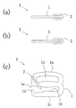
ここで、前記肩ストラップ用取付具3を肩ストラップに取り付け、衣類本体に脱着可能とした衣類として、ブラジャーを例にとり図6乃至図7に基づいて説明する。図6は、肩ストラップをブラジャー本体に脱着可能とした一例の肩ストラップ用取付具を有するブラジャーの裏側から見た部分説明図を示す。   Here, a bra is taken as an example of a garment that is attached to the shoulder strap and attachable to and detachable from the garment body, and will be described with reference to FIGS. FIG. 6 is a partial explanatory view seen from the back side of a brassiere having an example shoulder strap attachment that allows the shoulder strap to be attached to and detached from the brassiere body.

肩ストラップ8の端部は、前記肩ストラップ用取付具3の前記リング部1aの前記肩ストラップ取付用穴1bを通って反転されて、肩ストラップ縫製部8aで縫製されて前記肩ストラップ用取付具3に取り付けられている。   The end portion of the shoulder strap 8 is inverted through the shoulder strap attachment hole 1b of the ring portion 1a of the shoulder strap attachment 3, and is sewn at the shoulder strap sewing portion 8a to be sewed to the shoulder strap attachment. 3 is attached.

一方、布地からなる取付具用筒状部7bは、ブラジャー7のカップ部7aの裏側の上側端部に筒状の取付穴7dが形成できるように布地を丸めて、縫製部7cでカップ部7aの裏側に縫着されている。   On the other hand, the tubular portion 7b for a fixture made of fabric is rolled up so that a tubular mounting hole 7d can be formed at the upper end on the back side of the cup portion 7a of the brassiere 7, and the cup portion 7a is formed by the sewing portion 7c. It is sewn on the back side.

前記肩ストラップ8を前記ブラジャー7本体に取り付ける場合には、図7(a)に示すように、前記留め具2を一定角度回動させながら、図(b)に示すように、前記取付具用筒状部7bの前記取付穴7dに、前記肩ストラップ用取付具3の前記係止用ストランド1cを特定の一方向から差し込んで、前記係止用ストランド1cの前記係止部1dが前記取付穴7dの反対側に突き出るようにして取り付ける。このとき、前記係止ストランド1cは、前記取付具用筒状部7bよりも長く形成されているほうが好ましい。前記留め具2は、前記取付具1の2箇所の前記留め具用穴1f、1gに取り付けられている為、弾性を有しており一定角度回動されても、再び図(b)の矢印方向に反時計回り方向に回動し、図(c)に示すように、前記留め具2の前記曲折部2cは、再び前記係止部1dと当接する為、前記開口部1eは前記留め具2によって閉鎖され、前記取付具用筒状部7bは前記留め具2により抜けが防止されて、前記肩ストラップ用取付具3は前記取付具用筒状部7bに取り付けられた状態が維持され、前記肩ストラップ8は前記ブラジャー7本体より外れることはない。   When the shoulder strap 8 is attached to the body of the brassiere 7 as shown in FIG. 7A, the fastener 2 is rotated by a certain angle, and as shown in FIG. The locking strand 1c of the shoulder strap fixture 3 is inserted into the mounting hole 7d of the cylindrical portion 7b from a specific direction, and the locking portion 1d of the locking strand 1c is inserted into the mounting hole. Install so as to protrude to the opposite side of 7d. At this time, it is preferable that the locking strand 1c is formed longer than the tubular portion 7b for fixture. Since the fastener 2 is attached to the fastener holes 1f and 1g at the two locations of the fixture 1, the fastener 2 has elasticity and even when rotated by a certain angle, the arrow in FIG. As shown in FIG. 2C, the bent portion 2c of the fastener 2 comes into contact with the locking portion 1d again, so that the opening 1e is the fastener. 2, the fitting tubular portion 7 b is prevented from coming off by the fastener 2, and the shoulder strap fitting 3 is maintained attached to the fitting tubular portion 7 b, The shoulder strap 8 does not come off from the brassiere 7 body.

また、前記肩ストラップ8を前記ブラジャー7本体から外す場合には、前記留め具2を一定角度回動させながら、前記肩ストラップ用取付具3の前記係止用ストランド1cを前記取付具用筒状部7bの前記取付け穴7dから、差し込んだ方向と反対側に引き抜けばよい。   Further, when the shoulder strap 8 is removed from the brassiere 7 main body, the locking strand 1c of the shoulder strap attachment 3 is turned into the tubular shape for the attachment while the fastener 2 is rotated by a certain angle. What is necessary is just to pull out from the said attachment hole 7d of the part 7b to the opposite side to the insertion direction.

本実施例によれば、夏期等の暑い時期や、イブニングドレス等のアウターウェアを着用する場合において、ブラジャー等の下着類の前記肩ストラップ8の前記肩ストラップ用取付具3に設けられた前記留め具2を一定角度回動させることによって、脱着を容易に行うことができる。また、取付後においては、前記留め具2の前記曲折部2cは、再び前記係止部1dと当接する為、前記開口部1eは前記留め具2によって閉鎖され、前記取付具用筒状部7bは前記留め具2により抜けが防止されて、前記肩ストラップ用取付具3は前記取付具用筒状部7bに取り付けられた状態が維持され、前記肩ストラップ8は前記ブラジャー7本体より不用意に外れることはない。   According to the present embodiment, the fastener provided on the shoulder strap attachment 3 of the shoulder strap 8 of the underwear such as a brassiere when wearing hot clothes such as summer or outerwear such as an evening dress. Desorption can be easily performed by rotating the tool 2 by a certain angle. Further, after the attachment, the bent portion 2c of the fastener 2 comes into contact with the locking portion 1d again, so that the opening portion 1e is closed by the fastener 2, and the tubular portion 7b for the attachment tool. Is prevented from coming off by the fastener 2, the shoulder strap attachment 3 is maintained attached to the attachment tubular portion 7b, and the shoulder strap 8 is more careless than the brassiere 7 body. It will not come off.

次に、本発明の実施例2における肩ストラップ用取付具について、図8乃至図16に基づいて説明する。この実施例2おける発明は、実施例1と略同様の効果を有するが肩ストラップ用取付具構造において相違する。   Next, a shoulder strap attachment according to Embodiment 2 of the present invention will be described with reference to FIGS. The invention according to the second embodiment has substantially the same effect as that of the first embodiment, but is different in a shoulder strap attachment structure.

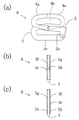
本発明の実施例2における肩ストラップ用取付具について図8乃至図16に基づいて説明する。図8(a)に示すように、取付具4は金属製で所定の厚みを有しており、リング部4a並びに係止用ストランド4cから構成されている。このとき、前記取付具1のように前記係止用ストランド4cの先端に図示されていない鉤状に曲がっている係止部を設けることもできる。また、前記リング部4aには肩ストラップを通すための変形楕円状の肩ストラップ取付用穴4bが設けられており、前記係止用ストランド4c側の前記リング部4aの中央部には、図8(a)に示す前記取付具4の紙面の裏面から表面へ向けて突設させ形成された環状凸部4e、一方前記裏面には環状凹部4fが設けられている。このとき、図9(a)に示すように、両端面に前記環状凸部4eを設けることもできるし、図10(a)に示すように、貫通穴4hとすることもできる。
また、前記リング部4aと前記係止ストランド4cの間には、図15に示すブラジャー7の前記取付具用筒状部7bを挿入させるための開口部4dが設けられている。さらに、前記係止用ストランド4cの開口部側の端部に、前記取付具4の両端面より所定の深さを有した同形状の環状凹部4gが設けられている。
A shoulder strap attachment according to Embodiment 2 of the present invention will be described with reference to FIGS. As shown in FIG. 8A, the fixture 4 is made of metal and has a predetermined thickness, and includes a ring portion 4a and a locking strand 4c. At this time, like the fixture 1, a locking portion that is bent in a hook shape (not shown) can be provided at the tip of the locking strand 4 c. Further, the ring portion 4a is provided with a deformed elliptical shoulder strap attachment hole 4b for allowing a shoulder strap to pass therethrough, and a central portion of the ring portion 4a on the side of the locking strand 4c is shown in FIG. An annular convex portion 4e formed by projecting from the rear surface to the front surface of the paper surface of the fixture 4 shown in (a), while an annular concave portion 4f is provided on the rear surface. At this time, as shown in FIG. 9A, the annular protrusions 4e can be provided on both end faces, or as shown in FIG. 10A, the through holes 4h can be formed.
Further, an opening 4d for inserting the fitting tubular portion 7b of the brassiere 7 shown in FIG. 15 is provided between the ring portion 4a and the locking strand 4c. Furthermore, an annular recess 4g having the same shape having a predetermined depth from both end faces of the fixture 4 is provided at the end of the locking strand 4c on the opening side.

留め具5は、金属製で図8(b)に示すように前記取付具4の前記環状凸部4eを中心として、前記リング部4aの左上側とほぼ同形状であるアーム部5aを有した略S字状の面5fと、同形状である面5gとが夫々対応するよう折曲平面部5hを介して折曲され、形成されている。このとき、前記面5fと前記面5gにおける両者の間隔は前記取付具4の厚みよりも僅かに広く設けられている。また、前記面5fの中央部には貫通穴5cが設けられ、前記面5gの前記貫通穴5cに対応する箇所には、外側端面から内側端面へ向けて突設させ形成された環状凸部5dが設けられている。
また、前記貫通穴5cは前記環状凸部4eよりも僅かに大きく、前記環状凸部5dは前記環状凹部4fよりも僅かに小さくなるよう形成されている。このとき、図9(b)に示すように、前記面5gにも面5fの前記貫通穴5cと対応するよう、前記貫通穴5cを設けることもできるし、図10(b)に示すように、前記面5fにも面5gの前記環状凸部5dと対応するよう、前記環状凸部5dを設けることもできる。また、図10(a)に示す前記貫通穴4hは前記環状凸部5dよりも僅かに大きくなるよう形成されている。
さらに、前記面5fと前記面5gの折曲平面部5h側の端部には、前記面5fと前記面5gの両端面より所定の深さ、外側から内側へ向けて突設させ形成された環状凸部5e及び係止面部5bとして直線部が設けられている。このとき、留め具5は、面5fのみとすることもできるし、面5fと同形状でない面(図示しない)とから形成することもできる。
The fastener 5 is made of metal and has an arm portion 5a having substantially the same shape as the upper left side of the ring portion 4a around the annular convex portion 4e of the fixture 4 as shown in FIG. 8 (b). The substantially S-shaped surface 5f and the surface 5g having the same shape are bent and formed via the bent flat surface portion 5h. At this time, the space between the surface 5f and the surface 5g is slightly wider than the thickness of the fixture 4. Further, a through hole 5c is provided at the center of the surface 5f, and an annular convex portion 5d formed to project from the outer end surface toward the inner end surface at a position corresponding to the through hole 5c of the surface 5g. Is provided.
The through hole 5c is slightly larger than the annular convex portion 4e, and the annular convex portion 5d is formed to be slightly smaller than the annular concave portion 4f. At this time, as shown in FIG. 9B, the surface 5g can also be provided with the through hole 5c so as to correspond to the through hole 5c of the surface 5f, or as shown in FIG. 10B. The annular convex portion 5d may be provided on the surface 5f so as to correspond to the annular convex portion 5d of the surface 5g. Further, the through hole 4h shown in FIG. 10A is formed to be slightly larger than the annular convex portion 5d.
Further, the end portions of the surface 5f and the surface 5g on the bent plane portion 5h side are formed to project from the both end surfaces of the surface 5f and the surface 5g to a predetermined depth from the outside to the inside. Linear portions are provided as the annular convex portion 5e and the locking surface portion 5b. At this time, the fastener 5 can be only the surface 5f, or can be formed from a surface (not shown) that is not the same shape as the surface 5f.

図11(a)に示すように、前記取付具4の前記環状凸部4eが前記留め具5の前記貫通穴5cに嵌合され、前記留め具5の前記環状凸部5dが前記取付具4の前記環状凹部4fに嵌合されて、前記留め具5は前記取付具4に取り付けられ、肩ストラップ用取付具6が構成されている。(仕様例1)また、図9の前記取付具4と前記留め具5が取付けられる場合には、前記取付具4の前記環状凸部4eが前記留め具5の前記貫通穴5cに嵌合して取付けられ(仕様例2)、図10の前記取付具4と前記留め具5が取付けられる場合には、前記取付具4の前記貫通穴4hに前記留め具5の前記環状凸部5dが嵌合して取付けられる。(仕様例3)また同時に、前記環状凸部5eも前記環状凹部4gに嵌合するよう構成されている。
また、請求項3乃至4記載の「凸部若しくは貫通穴」とは、夫々前記取付具4の前記環状凸部4e若しくは前記取付具4の前記貫通穴4hを示唆し、「貫通穴若しくは凸部」とは、夫々前記留め具5の前記貫通穴5c若しくは前記留め具5の前記環状凸部5dを示唆するものである。
このとき、図11において、前記留め具5の前記アーム部5aは、前記取付具4の前記リング部4aと重合するように形成されている。また、前記留め具5の前記折曲平面部5hは、前記取付具4の前記開口部4dを覆設するように形成されている。前記留め具5が面5fのみ及び面5fと同形状でない面(図示しない)とから形成されている場合は、前記取付具4の前記開口部4dは、略S字状の他端部により覆設される。また、前記面5fと前記面5gにおける両者の間隔は前記取付具4の厚みよりも僅かに広く設けられている為、図13(a)に示すように前記折曲平面部5hの端部が前記取付具4の前記リング部4aの外形に当接するまで、前記留め具5は前記取付具4の前記環状凸部4eと前記留め具5の前記環状凸部5dを中心に反時計回りに回動することができる。また、前記環状凸部5eを環状凹部とし、前記環状凹部4gを環状凸部と置換することもできる。
As shown in FIG. 11A, the annular convex portion 4 e of the fixture 4 is fitted into the through hole 5 c of the fastener 5, and the annular convex portion 5 d of the fastener 5 is fitted to the fixture 4. The fastener 5 is attached to the fixture 4 so as to constitute a shoulder strap fixture 6. (Specification Example 1) When the fixture 4 and the fastener 5 of FIG. 9 are attached, the annular convex portion 4e of the fixture 4 is fitted in the through hole 5c of the fastener 5. 10 (specification example 2), when the fixture 4 and the fastener 5 of FIG. 10 are attached, the annular protrusion 5d of the fastener 5 is fitted into the through hole 4h of the fixture 4. Can be installed together. (Specification Example 3) At the same time, the annular convex portion 5e is also configured to fit into the annular concave portion 4g.
Further, the “convex portion or through hole” according to claims 3 to 4 indicates the annular convex portion 4e of the fixture 4 or the through hole 4h of the fixture 4, respectively. "Indicates the through-hole 5c of the fastener 5 or the annular convex portion 5d of the fastener 5, respectively.
At this time, in FIG. 11, the arm portion 5 a of the fastener 5 is formed so as to overlap with the ring portion 4 a of the fixture 4. Further, the bent plane portion 5 h of the fastener 5 is formed so as to cover the opening 4 d of the fixture 4. When the fastener 5 is formed of only the surface 5f and a surface (not shown) that is not the same shape as the surface 5f, the opening 4d of the fixture 4 is covered with the other end portion of a substantially S shape. Established. Moreover, since the space | interval of both in the said surface 5f and the said surface 5g is provided slightly wider than the thickness of the said fixture 4, as shown to Fig.13 (a), the edge part of the said bending plane part 5h is shown. The fastener 5 rotates counterclockwise around the annular convex portion 4e of the fixture 4 and the annular convex portion 5d of the fastener 5 until it contacts the outer shape of the ring portion 4a of the fixture 4. Can move. Moreover, the said annular convex part 5e can be made into an annular recessed part, and the said annular recessed part 4g can also be substituted with an annular convex part.

ここで、前記肩ストラップ用取付具を肩ストラップに取り付け、衣類本体に脱着可能とした衣類として、ブラジャーを例にとり図15乃至図16に基づいて説明する。図15は、肩ストラップをブラジャー本体に脱着可能とした一例の仕様例1の肩ストラップ用取付具を有するブラジャーの裏側から見た部分図を示す。本説明は、図8に示す前記取付具4と前記留め具5を取付けた図11乃至図14仕様の肩ストラップ取付具6に関するものであるが、図9に示す仕様例2の前記取付具4と前記留め具5若しくは図10に示す仕様例3の前記取付具4と前記留め具5を取付けた肩ストラップ取付具6(図示しない仕様例2及び3)であっても、同様の効果を有するものである。   Here, a bra is taken as an example of a garment that is attached to the shoulder strap and detachable from the garment body, and will be described with reference to FIGS. FIG. 15 is a partial view seen from the back side of a brassiere having a shoulder strap attachment according to Specification Example 1 in which the shoulder strap can be attached to and detached from the brassiere body. This description relates to the shoulder strap attachment 6 of the specifications of FIGS. 11 to 14 to which the attachment 4 and the fastener 5 shown in FIG. 8 are attached, but the attachment 4 of the specification example 2 shown in FIG. 10 and the above-described fastener 5 of the specification example 3 shown in FIG. 10 and the shoulder strap attachment 6 to which the fastener 5 is attached (specification examples 2 and 3 not shown) have the same effect. Is.

肩ストラップ8の端部は、前記肩ストラップ用取付具6の前記リング部4aの前記肩ストラップ取付用穴4bを通って反転されて、肩ストラップ縫製部8aで縫製されて前記肩ストラップ用取付具6に取り付けられている。   The end portion of the shoulder strap 8 is inverted through the shoulder strap attachment hole 4b of the ring portion 4a of the shoulder strap attachment 6 and is sewn by the shoulder strap sewing portion 8a to be sewed by the shoulder strap attachment device. 6 is attached.

一方、布地からなる取付具用筒状部7bは、ブラジャー7のカップ部7aの裏側の上側端部に筒状の取付穴7dが形成できるように布地を丸めて、縫製部7cでカップ部7aの裏側に縫着されている。   On the other hand, the tubular portion 7b for a fixture made of fabric is rolled up so that a tubular mounting hole 7d can be formed at the upper end on the back side of the cup portion 7a of the brassiere 7, and the cup portion 7a is formed by the sewing portion 7c. It is sewn on the back side.

前記肩ストラップ8を前記ブラジャー7本体に取り付ける場合には、図16(a)に示すように、前記取付具4の前記環状凸部4eと前記留め具5の前記環状凸部5dを中心に前記留め具5を一定角度回動させた後、図16(b)に示すように、前記取付具用筒状部7bの前記取付け穴7dに、前記肩ストラップ用取付具6の前記係止用ストランド4cを特定の一方向から差し込んで、前記係止用ストランド4cの端部が前記取付穴7dの反対側に突き出るようにして取り付ける。このとき、前記係止ストランド4cは、前記取付具用筒状部7bよりも長く形成されているほうが好ましい。後に、図16(b)の矢印のように前記肩ストラップ8を引き上げると、前記肩ストラップ8と共に前記留め具5の前記アーム部5aも引き上げられ、図16(c)に示すように、前記留め具5の前記アーム部5aは、再び前記取付具4の前記リング部4aと重合し、前記留め具5の前記環状凸部5eも前記取付具4の前記環状凹部4gと嵌合する為、前記開口部4dは前記留め具5の略S字状の他端部、又は前記折曲平面部5hによって覆設される。
また、前記留め具5の前記アーム部5aは、常に前記肩ストラップ8により引き上げられており、前記留め具5は回動することはない為、前記取付具用筒状部7bは前記留め具5の略S字状の他端部、又は前記係止面部5bにより抜けが防止されて、前記肩ストラップ用取付具6は前記取付具用筒状部7bに取り付けられた状態が維持され、前記肩ストラップ8は前記ブラジャー7本体より外れることはない。
When the shoulder strap 8 is attached to the brassiere 7 body, the annular protrusion 4e of the attachment 4 and the annular protrusion 5d of the fastener 5 are centered as shown in FIG. After the fastener 5 is rotated by a certain angle, as shown in FIG. 16B, the locking strand of the shoulder strap attachment 6 is inserted into the attachment hole 7d of the attachment tubular portion 7b. 4c is inserted from one specific direction, and attached so that the end of the locking strand 4c protrudes to the opposite side of the mounting hole 7d. At this time, the locking strand 4c is preferably formed longer than the tubular portion 7b for fixture. Later, when the shoulder strap 8 is pulled up as shown by the arrow in FIG. 16 (b), the arm portion 5a of the fastener 5 is also lifted together with the shoulder strap 8, and as shown in FIG. The arm portion 5a of the fixture 5 is again overlapped with the ring portion 4a of the fixture 4, and the annular convex portion 5e of the fastener 5 is also fitted with the annular concave portion 4g of the fixture 4. The opening 4d is covered by the substantially S-shaped other end of the fastener 5 or the bent flat surface 5h.
Further, the arm portion 5a of the fastener 5 is always pulled up by the shoulder strap 8, and the fastener 5 does not rotate. The other end of the substantially S-shape or the locking surface portion 5b prevents the shoulder strap attachment device 6 from being attached to the attachment tubular portion 7b. The strap 8 does not come off from the brassiere 7 body.

また、前記肩ストラップ8を前記ブラジャー7本体から外す場合には、前記留め具5を一定角度回動させた後、前記肩ストラップ用取付具6の前記係止用ストランド4cを前記取付具用筒状部7bの前記取付け穴7dから、差し込んだ方向と反対側に引き抜けばよい。   When the shoulder strap 8 is removed from the brassiere 7 body, the fastener 5 is rotated by a certain angle, and then the locking strand 4c of the shoulder strap attachment 6 is connected to the attachment cylinder. What is necessary is just to pull out from the said attachment hole 7d of the shape part 7b on the opposite side to the insertion direction.

本実施例によれば、夏期等の暑い時期や、イブニングドレス等のアウターウェアを着用する場合において、ブラジャー等の下着類の前記肩ストラップ8の前記肩ストラップ用取付具6に設けられた前記留め具5を前記取付具4の前記環状凸部4eと前記留め具5の前記環状凸部5dを中心に一定角度回動させることによって、脱着を容易に行うことができる。また、取付後において前記留め具5の前記アーム部5aは、再び前記取付具4の前記リング部4aと重合し、前記留め具5の前記環状凸部5eも前記取付具4の前記環状凹部4gと嵌合する為、前記開口部4dは前記留め具5の略S字状の他端部、又は前記折曲平面部5hによって覆設される。また、前記留め具5の前記アーム部5aは、常に前記肩ストラップ8により引き上げられており、前記留め具5は回動することはない為、前記取付具用筒状部7bは前記留め具5の略S字状の他端部、又は前記係止部5bにより抜けが防止されて、前記肩ストラップ用取付具6は前記取付具用筒状部7bに取り付けられた状態が維持され、前記肩ストラップ8は前記ブラジャー7本体より不用意に外れることはない。   According to the present embodiment, the fastener provided on the shoulder strap attachment 6 of the shoulder strap 8 of underwear such as a brassiere when wearing hot clothes such as summer or outerwear such as an evening dress. Detachment can be easily performed by rotating the tool 5 by a fixed angle around the annular convex part 4e of the fixture 4 and the annular convex part 5d of the fastener 5. Further, after the attachment, the arm portion 5 a of the fastener 5 overlaps with the ring portion 4 a of the fixture 4 again, and the annular protrusion 5 e of the fastener 5 is also the annular recess 4 g of the attachment 4. The opening 4d is covered with the other end portion of the substantially S-shape of the fastener 5 or the bent plane portion 5h. Further, the arm portion 5a of the fastener 5 is always pulled up by the shoulder strap 8, and the fastener 5 does not rotate. The other end of the substantially S-shape or the locking portion 5b prevents the shoulder strap attachment device 6 from being attached to the attachment tubular portion 7b. The strap 8 is not inadvertently detached from the brassiere 7 body.

また、本発明は、上記実施例には限られず、各種のカップ付き女性用衣類、例えば、ブラスリット、ボディースーツ、キャミソール等においても採用することができ、図17に示すように鞄等のショルダーベルトの連結環としても採用することができる。これにより、ナス環による構成部品の点数よりも部品点数を削減することができ、生産コストも削減することができる。   In addition, the present invention is not limited to the above-described embodiments, and can be applied to various types of women's clothing with cups, such as bra slits, body suits, camisoles, etc., as shown in FIG. It can also be employed as a belt connection ring. Thereby, the number of parts can be reduced rather than the number of component parts by the eggplant ring, and the production cost can also be reduced.

また、前記取付具1と前記留め具2より構成される前記肩ストラップ用取付具3及び前記取付具4と前記留め具5より構成される前記肩ストラップ用取付具6の材質は、金属製に限らず樹脂製とすることもできる。   Further, the shoulder strap fixture 3 constituted by the fixture 1 and the fastener 2 and the shoulder strap fixture 6 constituted by the fixture 4 and the fastener 5 are made of metal. Not limited to resin.

本発明の実施例1における肩ストラップ用取付具の(a)取付具正面図及びA―Aによる垂直断面図、(b)留め具正面図及び右側面図である。It is the (a) fixture front view and vertical sectional view by AA of the shoulder strap fixture in Example 1 of this invention, (b) The fastener front view and the right view. 本発明の実施例1における肩ストラップ用取付具の(a)正面図、(b)右側面図、及び(c)左側面図である。It is the (a) front view, (b) right side view, and (c) left side view of the shoulder strap fixture in Embodiment 1 of the present invention. 本発明の実施例1における肩ストラップ用取付具の(a)平面図、(b)底面図、及び(c)背面図である。It is (a) top view, (b) bottom view, and (c) back view of the shoulder strap fixture in Embodiment 1 of the present invention. 本発明の実施例1における肩ストラップ用取付具の留め具を一定角度回動させたときの(a)正面図、(b)右側面図、及び(c)左側面図である。It is (a) front view, (b) right side view, and (c) left side view when the fastener of the shoulder strap attachment in Embodiment 1 of the present invention is rotated by a certain angle. 本発明の実施例1における肩ストラップ用取付具の留め具を一定角度回動させたときの(a)平面図、(b)底面図、及び(c)背面図である。It is (a) top view, (b) bottom view, and (c) back view when the fastener of the shoulder strap fixture in Example 1 of the present invention is rotated by a certain angle. 本発明の実施例1における肩ストラップ用取付具を有した肩ストラップをブラジャーに取り付ける際、裏側から見た部分説明図である。It is the partial explanatory view seen from the back side, when attaching the shoulder strap which has the attachment tool for shoulder straps in Example 1 of this invention to a brassiere. 本発明の実施例1における肩ストラップ用取付具を有した肩ストラップをブラジャーに取り付ける際、裏側から見た部分拡大図の(a)留め具回動時、(b)肩ストラップ用取付具装着図、及び(c)肩ストラップ用取付具装着完了図である。When attaching the shoulder strap having the shoulder strap attachment in the first embodiment of the present invention to the brassiere, (a) when the fastener is rotated, (b) the shoulder strap attachment attached view, as seen from the back side. (C) Shoulder strap attachment complete. 本発明の実施例2における仕様例1の肩ストラップ用取付具の(a)取付具正面図及び右側面図、(b)留め具正面図、右側面図及び底面図である。It is the (a) fixture front view and right side view of the fixture for shoulder straps of the specification example 1 in Example 2 of this invention, (b) The fastener front view, right side view, and bottom view. 本発明の実施例2における仕様例2の肩ストラップ用取付具の(a)取付具正面図及び右側面図、(b)留め具正面図、右側面図及び底面図である。It is the (a) fixture front view and right side view of the fixture for shoulder straps of the specification example 2 in Example 2 of this invention, (b) The fastener front view, right side view, and bottom view. 本発明の実施例2における仕様例3の肩ストラップ用取付具の(a)取付具正面図及び右側面図、(b)留め具正面図、右側面図及び底面図である。It is the (a) fixture front view and right side view of the fixture for shoulder straps of the specification example 3 in Example 2 of this invention, (b) The fastener front view, right side view, and bottom view. 本発明の実施例2における仕様例1の肩ストラップ用取付具の(a)正面図、(b)右側面図、及び(c)左側面図である。It is the (a) front view, the (b) right side view, and the (c) left side view of the shoulder strap attachment of the specification example 1 in the second embodiment of the present invention. 本発明の実施例2における仕様例1の肩ストラップ用取付具の(a)平面図、(b)底面図、及び(c)背面図である。It is the (a) top view, (b) bottom view, and (c) back view of the shoulder strap attachment of the specification example 1 in Example 2 of the present invention. 本発明の実施例2における仕様例1の肩ストラップ用取付具の留め具を一定角度回動させたときの(a)正面図、(b)右側面図、及び(c)左側面図である。It is the (a) front view, (b) right side view, and (c) left side view when the fastener of the shoulder strap attachment of the specification example 1 in the second embodiment of the present invention is rotated by a certain angle. . 本発明の実施例2における仕様例1の肩ストラップ用取付具の留め具を一定角度回動させたときの(a)平面図、(b)底面図、及び(c)背面図である。It is the (a) top view, (b) bottom view, and (c) back view when the fastener of the shoulder strap attachment of the specification example 1 in Example 2 of the present invention is rotated by a certain angle. 本発明の実施例2における仕様例1の肩ストラップ用取付具を有した肩ストラップをブラジャーに取り付ける際、裏側から見た部分図である。It is the fragmentary view seen from the back side, when attaching the shoulder strap which has the attachment tool for shoulder straps of the example 1 of specification in Example 2 of this invention to a brassiere. 本発明の実施例2における仕様例1の肩ストラップ用取付具を有した肩ストラップをブラジャーに取り付ける際、裏側から見た部分拡大図の(a)留め具回動時、(b)肩ストラップ用取付具装着図、及び(c)肩ストラップ用取付具装着完了図である。When attaching the shoulder strap having the shoulder strap attachment of the specification example 1 of the second embodiment of the present invention to the brassiere, (a) when the fastener is rotated, (b) for the shoulder strap, as viewed from the back side. FIG. 3 is a mounting diagram of a mounting tool, and (c) a mounting diagram of a mounting tool for a shoulder strap. 鞄等の連結環に(a)本発明の実施例1における肩ストラップ用取付具を用いたときの参考正面図、及び(b)本発明の実施例2における仕様例1の肩ストラップ用取付具を用いたときの参考正面図である。(A) A reference front view when using the shoulder strap attachment according to the first embodiment of the present invention for a connecting ring such as a bag, and (b) the shoulder strap attachment according to the first specification according to the second embodiment of the present invention. It is a reference front view when using. 従来の肩ストラップ用取付具の正面図である。It is a front view of the conventional fixture for shoulder straps.

符号の説明Explanation of symbols

1 取付具
1a リング部
1b 肩ストラップ取付用穴
1c 係止用ストランド
1d 係止部
1e 開口部
1f、1g 留め具用穴
1h 係止面部
2 留め具
2a、2b 留め具端部
2c 曲折部
3 肩ストラップ用取付具
4 取付具
4a リング部
4b 肩ストラップ取付用穴
4c 係止用ストランド
4d 開口部
4e 環状凸部
4f、4g 環状凹部
4h 貫通穴
5a アーム部
5b 係止面部
5c 貫通穴
5d、5e 環状凸部
5f、5g 面
5h 折曲平面部
6 肩ストラップ用取付具
7 ブラジャー
7a カップ部
7b 取付具用筒状部
7c 縫製部
7d 取付穴
8 肩ストラップ
8a 肩ストラップ縫製部
9 ショルダーベルト
9a ショルダーベルト縫製部
10 取付金具
11 バッグ部ストラップ
11a バッグ部ストラップ縫製部
DESCRIPTION OF SYMBOLS 1 Attachment 1a Ring part 1b Shoulder strap attachment hole 1c Locking strand 1d Locking part 1e Opening part 1f, 1g Fastening hole 1h Locking surface part 2 Fastening element 2a, 2b Fastening edge part 2c Bending part 3 Shoulder Strap attachment 4 Attachment 4a Ring portion 4b Shoulder strap attachment hole 4c Locking strand 4d Opening portion 4e Annular protrusion 4f, 4g Annular recess 4h Through hole 5a Arm portion 5b Locking surface portion 5c Through hole 5d, 5e Annular Projection 5f, 5g Surface 5h Bending plane 6 Shoulder strap attachment 7 Bra 7a Cup 7b Attachment cylindrical 7c Sewing part 7d Attachment hole 8 Shoulder strap 8a Shoulder strap sewing part 9 Shoulder belt 9a Shoulder belt sewing Part 10 Mounting bracket 11 Bag part strap 11a Bag part strap sewing part

Claims (8)

カップ付き女性用衣類の本体に脱着可能とする肩ストラップ用取付具において、
所定の厚みで、肩ストラップ端部に取り付けられるリング部、肩ストラップ取付用穴、開口部、及び係止用ストランドを有し、係止用ストランドの先端が鉤状に曲がっている係止部を有した取付具と、
屈曲性を保持したバネ部材の留め具からなり、
取付具の係止用ストランドの係止部を有するリング部の一端側に係止ストランドに対して交会方向に設けられた貫通穴に嵌合させて、
留め具の曲折部が開口部内の係止部の内側と当接し、
留め具が取り付け具の開口部を閉鎖するようにして、取り付けたことを特徴とする肩ストラップ用取付具。
In the shoulder strap attachment that can be attached to and detached from the body of women's clothing with a cup,
A locking portion having a ring portion attached to the shoulder strap end portion, a shoulder strap mounting hole, an opening portion, and a locking strand with a predetermined thickness, and the leading end of the locking strand bent in a hook shape. A fixture having
It consists of a spring member fastener that retains flexibility,
Fit one end side of the ring portion having the locking portion of the locking strand of the fixture to a through hole provided in the direction of intersection with the locking strand,
The bent portion of the fastener comes into contact with the inside of the locking portion in the opening,
A shoulder strap attachment device, wherein the fastener is attached so as to close an opening of the attachment device.
屈曲性を保持したバネ部材の留め具が、
両端を内側に曲げた線材で、一端部を他端部より長くした形状からなり、
取付具の係止用ストランドの係止部を有するリング部の一端側に係止ストランドに対して垂直方向に設けられた貫通穴に嵌合させて、
留め具の曲折部が開口部内の係止部の内側と当接し、
留め具が取り付け具の開口部を閉鎖するようにして、取り付けたことを特徴とする請求項1記載の肩ストラップ用取付具。
The spring member retains flexibility,
It consists of a wire with both ends bent inward and one end is longer than the other end.
Fit one end side of the ring portion having the locking portion of the locking strand of the fixture to a through hole provided in a direction perpendicular to the locking strand,
The bent portion of the fastener comes into contact with the inside of the locking portion in the opening,
The shoulder strap attachment device according to claim 1, wherein the attachment device is attached so as to close an opening of the attachment device.
カップ付き女性用衣類の本体に脱着可能とする肩ストラップ用取付具において、
所定の厚みで、肩ストラップ端部に取り付けられるリング部、肩ストラップ取付用穴、開口部、及び係止用ストランドを有した取付具と、
取付具のリング部と重合するように設けられたアーム部を有する略S字状の面を有する留め具からなり、
取付具の一端面の係止用ストランド側のリング部の中央部に設けられた凸部若しくは貫通穴を、
留め具の中央部に設けられた貫通穴若しくは凸部に嵌合させて、
取付具の開口部を留め具の略S字状の他端部により覆設するようにして、取り付けたことを特徴とする肩ストラップ用取付具。
In the shoulder strap attachment that can be attached to and detached from the body of women's clothing with a cup,
A fixture having a ring portion, a shoulder strap mounting hole, an opening, and a locking strand attached to the shoulder strap end portion with a predetermined thickness;
A fastener having a substantially S-shaped surface with an arm portion provided to overlap with the ring portion of the fixture;
A convex part or a through hole provided in the center part of the ring part on the locking strand side of one end face of the fixture,
Fit into the through hole or convex part provided in the central part of the fastener,
A shoulder strap attachment device, wherein the attachment portion is attached so that the opening of the attachment device is covered with the other end portion of the substantially S-shape of the fastener.
取付具のリング部と重合するように設けられたアーム部を有する略S字状の面を有する留め具が、
取付具のリング部と重合するように設けられたアーム部を有する略S字状の面と、同形状である面とが夫々対応するよう、折曲平面部を介して折曲され形成され、
取付具の一端面の係止用ストランド側のリング部の中央部に設けられた凸部若しくは貫通穴を、
留め具の一端面の中央部に設けられた貫通穴若しくは凸部に嵌合させて、
取付具の開口部を留め具の折曲平面部により覆設するようにして、取り付けたことを特徴とする請求項3記載の肩ストラップ用取付具。
A fastener having a generally S-shaped surface with an arm portion provided to overlap with the ring portion of the fixture,
The substantially S-shaped surface having an arm portion provided so as to overlap with the ring portion of the fixture, and the surface having the same shape correspond to each other and are formed by being bent through a bent plane portion,
A convex part or a through hole provided in the center part of the ring part on the locking strand side of one end face of the fixture,
Fit into the through-hole or convex part provided in the central part of one end face of the fastener,
The shoulder strap attachment device according to claim 3, wherein the attachment portion is attached so that the opening portion of the attachment device is covered with the bent flat portion of the fastener.
カップ付き女性用衣類の本体に脱着可能とする肩ストラップ用取付具を端部に有する肩ストラップにおいて、
端部に請求項1又は請求項2に記載の肩ストラップ用取付具を具備したことを特徴とする肩ストラップ。
A shoulder strap having a shoulder strap attachment at its end that is detachable from the body of a female clothing with a cup,
A shoulder strap comprising the shoulder strap attachment according to claim 1 or 2 at an end.
カップ付き女性用衣類の本体に脱着可能とする肩ストラップ用取付具を端部に有する肩ストラップにおいて、
端部に請求項3又は請求項4に記載の肩ストラップ用取付具を具備したことを特徴とする肩ストラップ。
A shoulder strap having a shoulder strap attachment at its end that is detachable from the body of a female clothing with a cup,
A shoulder strap comprising the shoulder strap fitting according to claim 3 or 4 at an end.
肩ストラップを衣類本体に脱着可能としたカップ付き女性用衣類において、
請求項5に記載の肩ストラップを具備したことを特徴とするカップ付き女性用衣類。
In women's clothing with cups that can detach the shoulder strap to the clothing body,
A women's garment with a cup, comprising the shoulder strap according to claim 5.
肩ストラップを衣類本体に脱着可能としたカップ付き女性用衣類において、
請求項6に記載の肩ストラップを具備したことを特徴とするカップ付き女性用衣類。
In women's clothing with cups that can detach the shoulder strap to the clothing body,
A female garment with a cup, comprising the shoulder strap according to claim 6.
JP2006171368A 2006-06-21 2006-06-21 Shoulder strap fittings, women's clothing with shoulder straps and cups Expired - Fee Related JP4841327B2 (en)

Priority Applications (1)

Application Number Priority Date Filing Date Title
JP2006171368A JP4841327B2 (en) 2006-06-21 2006-06-21 Shoulder strap fittings, women's clothing with shoulder straps and cups

Applications Claiming Priority (1)

Application Number Priority Date Filing Date Title
JP2006171368A JP4841327B2 (en) 2006-06-21 2006-06-21 Shoulder strap fittings, women's clothing with shoulder straps and cups

Publications (2)

Publication Number Publication Date
JP2008002004A true JP2008002004A (en) 2008-01-10
JP4841327B2 JP4841327B2 (en) 2011-12-21

Family

ID=39006620

Family Applications (1)

Application Number Title Priority Date Filing Date
JP2006171368A Expired - Fee Related JP4841327B2 (en) 2006-06-21 2006-06-21 Shoulder strap fittings, women's clothing with shoulder straps and cups

Country Status (1)

Country Link
JP (1) JP4841327B2 (en)

Cited By (10)

* Cited by examiner, † Cited by third party
Publication number Priority date Publication date Assignee Title
KR100793234B1 (en) * 2007-03-14 2008-01-10 주식회사 지피알 Apparatus for extracting sludge from waste tire
KR100798622B1 (en) * 2007-09-19 2008-01-28 김양수 Electric current unit for removing static electricity
KR100801059B1 (en) * 2006-08-02 2008-02-04 삼성전자주식회사 Driver circuit of semiconductor memory device for decreasing leakage current
KR100808771B1 (en) * 2006-12-18 2008-02-29 덴소풍성전자(주) The word-panel of the gauge which implements the cubic effect
KR100849308B1 (en) * 2001-12-07 2008-07-29 삼성전자주식회사 Rotation angle supporting device for mobile phone camera lens housing
KR100851666B1 (en) * 2006-09-13 2008-08-13 주식회사 케이티 Message Posting System For Establishing Priority Order Of Search Result And Search Advertisement System And Method Thereof
KR100863179B1 (en) * 2007-12-12 2008-10-13 현대자동차주식회사 Shelf for bus
KR100863618B1 (en) * 2007-04-19 2008-10-15 바이오스펙트럼 주식회사 Compositions for improving skin conditions comprising protocatechuic acid
US8270834B2 (en) 2007-06-13 2012-09-18 West Jr Lamar E Frequency modulated burst mode optical system
WO2022234348A1 (en) * 2021-05-04 2022-11-10 林志荣 Undergarment buckle assembly

Citations (3)

* Cited by examiner, † Cited by third party
Publication number Priority date Publication date Assignee Title
JPS5658213A (en) * 1979-10-05 1981-05-21 Allied Chem Iron core for electromagnetic induction device
JPS6270121A (en) * 1985-09-20 1987-03-31 Matsushita Electric Ind Co Ltd Sheet feeder
JPH0360990U (en) * 1989-10-16 1991-06-14

Patent Citations (3)

* Cited by examiner, † Cited by third party
Publication number Priority date Publication date Assignee Title
JPS5658213A (en) * 1979-10-05 1981-05-21 Allied Chem Iron core for electromagnetic induction device
JPS6270121A (en) * 1985-09-20 1987-03-31 Matsushita Electric Ind Co Ltd Sheet feeder
JPH0360990U (en) * 1989-10-16 1991-06-14

Cited By (10)

* Cited by examiner, † Cited by third party
Publication number Priority date Publication date Assignee Title
KR100849308B1 (en) * 2001-12-07 2008-07-29 삼성전자주식회사 Rotation angle supporting device for mobile phone camera lens housing
KR100801059B1 (en) * 2006-08-02 2008-02-04 삼성전자주식회사 Driver circuit of semiconductor memory device for decreasing leakage current
KR100851666B1 (en) * 2006-09-13 2008-08-13 주식회사 케이티 Message Posting System For Establishing Priority Order Of Search Result And Search Advertisement System And Method Thereof
KR100808771B1 (en) * 2006-12-18 2008-02-29 덴소풍성전자(주) The word-panel of the gauge which implements the cubic effect
KR100793234B1 (en) * 2007-03-14 2008-01-10 주식회사 지피알 Apparatus for extracting sludge from waste tire
KR100863618B1 (en) * 2007-04-19 2008-10-15 바이오스펙트럼 주식회사 Compositions for improving skin conditions comprising protocatechuic acid
US8270834B2 (en) 2007-06-13 2012-09-18 West Jr Lamar E Frequency modulated burst mode optical system
KR100798622B1 (en) * 2007-09-19 2008-01-28 김양수 Electric current unit for removing static electricity
KR100863179B1 (en) * 2007-12-12 2008-10-13 현대자동차주식회사 Shelf for bus
WO2022234348A1 (en) * 2021-05-04 2022-11-10 林志荣 Undergarment buckle assembly

Also Published As

Publication number Publication date
JP4841327B2 (en) 2011-12-21

Similar Documents

Publication Publication Date Title
JP4841327B2 (en) Shoulder strap fittings, women&#39;s clothing with shoulder straps and cups
US20110055994A1 (en) Woman&#39;s garment with side closure devices
JP3111240U (en) tie
JP2008156783A (en) Front pad cloth with locking device, and ladies&#39; garment with front pad cloth
JP4658164B2 (en) Cup parts for clothing with cups
JP6197210B1 (en) Towel clip
EP2785073A1 (en) Bluetooth listening device with decorative function
JP3113686U (en) Necklace fixture
JP3124921U (en) Belt bracket
JP4291702B2 (en) Clothing with cup
JP3143608U (en) Women&#39;s clothing
JP3108407U (en) Sticky bra cover
JP3092009U (en) Brassiere and brassier
JP2007135853A (en) Strap connector, breast pad and brassiere using the same
CN213215530U (en) Silica gel movement adjustment shoulder belt
JP3153429U (en) Clothes strap
JP3129630U (en) Jewelry
JP3056129U (en) shirt
JP3060990U (en) Brassiere
JP2008274497A (en) Attaching tool for shoulder strap, shoulder strap, and women&#39;s garment with cup
KR100465018B1 (en) shoulder strings and length adjustment device thereof
KR200274785Y1 (en) cup attachable brassiere
JPH0324570Y2 (en)
WO2012098678A1 (en) Fastener
JPH08100307A (en) Underwear

Legal Events

Date Code Title Description
A621 Written request for application examination

Free format text: JAPANESE INTERMEDIATE CODE: A621

Effective date: 20090127

A977 Report on retrieval

Free format text: JAPANESE INTERMEDIATE CODE: A971007

Effective date: 20101111

A131 Notification of reasons for refusal

Free format text: JAPANESE INTERMEDIATE CODE: A131

Effective date: 20101130

A521 Written amendment

Free format text: JAPANESE INTERMEDIATE CODE: A523

Effective date: 20101222

A131 Notification of reasons for refusal

Free format text: JAPANESE INTERMEDIATE CODE: A131

Effective date: 20110614

A521 Written amendment

Free format text: JAPANESE INTERMEDIATE CODE: A523

Effective date: 20110624

TRDD Decision of grant or rejection written
A01 Written decision to grant a patent or to grant a registration (utility model)

Free format text: JAPANESE INTERMEDIATE CODE: A01

Effective date: 20110920

A01 Written decision to grant a patent or to grant a registration (utility model)

Free format text: JAPANESE INTERMEDIATE CODE: A01

A61 First payment of annual fees (during grant procedure)

Free format text: JAPANESE INTERMEDIATE CODE: A61

Effective date: 20111004

R150 Certificate of patent or registration of utility model

Free format text: JAPANESE INTERMEDIATE CODE: R150

FPAY Renewal fee payment (event date is renewal date of database)

Free format text: PAYMENT UNTIL: 20141014

Year of fee payment: 3

R250 Receipt of annual fees

Free format text: JAPANESE INTERMEDIATE CODE: R250

R250 Receipt of annual fees

Free format text: JAPANESE INTERMEDIATE CODE: R250

R250 Receipt of annual fees

Free format text: JAPANESE INTERMEDIATE CODE: R250

LAPS Cancellation because of no payment of annual fees