JP2007536143A - Seat assembly and method with movable seat and backrest - Google Patents
Seat assembly and method with movable seat and backrest Download PDFInfo
- Publication number
- JP2007536143A JP2007536143A JP2007511063A JP2007511063A JP2007536143A JP 2007536143 A JP2007536143 A JP 2007536143A JP 2007511063 A JP2007511063 A JP 2007511063A JP 2007511063 A JP2007511063 A JP 2007511063A JP 2007536143 A JP2007536143 A JP 2007536143A
- Authority
- JP
- Japan
- Prior art keywords
- seat
- backrest
- assembly
- frame
- seat assembly
- Prior art date
- Legal status (The legal status is an assumption and is not a legal conclusion. Google has not performed a legal analysis and makes no representation as to the accuracy of the status listed.)
- Pending
Links
Images


Classifications
-
- B—PERFORMING OPERATIONS; TRANSPORTING
- B60—VEHICLES IN GENERAL
- B60N—SEATS SPECIALLY ADAPTED FOR VEHICLES; VEHICLE PASSENGER ACCOMMODATION NOT OTHERWISE PROVIDED FOR
- B60N2/00—Seats specially adapted for vehicles; Arrangement or mounting of seats in vehicles
- B60N2/02—Seats specially adapted for vehicles; Arrangement or mounting of seats in vehicles the seat or part thereof being movable, e.g. adjustable
- B60N2/04—Seats specially adapted for vehicles; Arrangement or mounting of seats in vehicles the seat or part thereof being movable, e.g. adjustable the whole seat being movable
- B60N2/06—Seats specially adapted for vehicles; Arrangement or mounting of seats in vehicles the seat or part thereof being movable, e.g. adjustable the whole seat being movable slidable
- B60N2/07—Slide construction
- B60N2/0735—Position and orientation of the slide as a whole
- B60N2/0745—Position and orientation of the slide as a whole the slide path being curved
-
- B—PERFORMING OPERATIONS; TRANSPORTING
- B60—VEHICLES IN GENERAL
- B60N—SEATS SPECIALLY ADAPTED FOR VEHICLES; VEHICLE PASSENGER ACCOMMODATION NOT OTHERWISE PROVIDED FOR
- B60N2/00—Seats specially adapted for vehicles; Arrangement or mounting of seats in vehicles
- B60N2/24—Seats specially adapted for vehicles; Arrangement or mounting of seats in vehicles for particular purposes or particular vehicles
- B60N2/42—Seats specially adapted for vehicles; Arrangement or mounting of seats in vehicles for particular purposes or particular vehicles the seat constructed to protect the occupant from the effect of abnormal g-forces, e.g. crash or safety seats
- B60N2/427—Seats or parts thereof displaced during a crash
- B60N2/42727—Seats or parts thereof displaced during a crash involving substantially rigid displacement
- B60N2/42736—Seats or parts thereof displaced during a crash involving substantially rigid displacement of the whole seat
-
- B—PERFORMING OPERATIONS; TRANSPORTING
- B60—VEHICLES IN GENERAL
- B60N—SEATS SPECIALLY ADAPTED FOR VEHICLES; VEHICLE PASSENGER ACCOMMODATION NOT OTHERWISE PROVIDED FOR
- B60N2/00—Seats specially adapted for vehicles; Arrangement or mounting of seats in vehicles
- B60N2/24—Seats specially adapted for vehicles; Arrangement or mounting of seats in vehicles for particular purposes or particular vehicles
- B60N2/42—Seats specially adapted for vehicles; Arrangement or mounting of seats in vehicles for particular purposes or particular vehicles the seat constructed to protect the occupant from the effect of abnormal g-forces, e.g. crash or safety seats
- B60N2/427—Seats or parts thereof displaced during a crash
- B60N2/42727—Seats or parts thereof displaced during a crash involving substantially rigid displacement
- B60N2/42754—Seats or parts thereof displaced during a crash involving substantially rigid displacement of the cushion
- B60N2/42763—Seats or parts thereof displaced during a crash involving substantially rigid displacement of the cushion with anti-submarining systems
Abstract
【解決手段】乗り物用のシート組立体(21)であって、シート(22)と、上に凹である弓形の経路に沿って動けるようにシート(22)を取り付けるシート取付組立体(20)と、バックレスト部材(23)を備えたバックレスト組立体(25)であって、その下部部分(18)はシート(22)と共に弓形に動くように結合され、上部部分(99)は垂直に延びる方向に動けるように取り付けられた上記バックレスト組立体と、を具備している。バックレスト組立体(25)はさらに、リクライニング機構(32,33)を具備している。また、シート組立体を提供する方法も開示され、かかる方法は、上に凹である弓形の経路に沿って動けるようにシート(22)を取り付ける段階と、シートの近くにバックレスト(25)を取り付ける段階と、バックレスト下部部分(18)をシート(22)と共に動けるように結合する段階と、バックレストの上部部分(99)を垂直に延びて動けるように取り付ける段階と、を具備する。
【選択図】図1A seat assembly (21) for a vehicle, the seat mounting assembly (20) for mounting the seat (22) and the seat (22) for movement along an arcuate path that is concave upwards. A backrest assembly (25) with a backrest member (23), the lower part (18) of which is joined together with the seat (22) to move in an arcuate manner and the upper part (99) is vertically And the backrest assembly mounted so as to be movable in the extending direction. The backrest assembly (25) further includes a reclining mechanism (32, 33). A method of providing a seat assembly is also disclosed, the method comprising attaching a seat (22) for movement along an arcuate path that is concave upward, and a backrest (25) near the seat. Attaching the backrest lower portion (18) for movement with the seat (22) and attaching the backrest upper portion (99) for vertical movement.
[Selection] Figure 1
Description
本発明は、概略的には、自動車、航空機、及び船舶のためのシート組立体、および、静止したシート組立体に関し、より詳しくは、可動なシートと可動なバックレストを備えてなるシート組立体及びその提供方法に関する。 The present invention generally relates to seat assemblies for automobiles, aircraft, and ships, and stationary seat assemblies, and more particularly, a seat assembly comprising a movable seat and a movable backrest. And a method for providing the same.
様々なタイプの乗り物に採用されるシート組立体の安全性を改良するために、また、乗り物及び静止した用途に使用されるシートの安楽性を改善するために、かなりの努力が向けられて来た。そうした努力のうち、代表的なものとして、本出願人による、米国特許第4,650,249号明細書、第5,244明細書,252号明細書、第5,460,427号明細書、第5,558,399号明細書、及び第5,735,574号明細書がある。こうした従来技術によるシート組立体にあっては、乗り物が急減速する際の、体の姿勢と、筋肉及び骨格に生じる力とを制御すべく、シートの運動をデザインすることによって、シートの安全性と安楽性とを改善しようとして来た。他の多数の特許も、同一の一般的な目標を求めたものである。 Considerable efforts have been directed to improving the safety of seat assemblies employed in various types of vehicles and to improve the comfort of seats used in vehicles and stationary applications. It was. Among such efforts, representative examples of the present applicants are US Pat. Nos. 4,650,249, 5,244,252, 5,460,427, There are 5,558,399 specification and 5,735,574 specification. In such prior art seat assemblies, seat safety is designed by controlling the body posture and the forces generated in the muscles and skeleton when the vehicle suddenly decelerates. And trying to improve comfort and comfort. Many other patents seek the same general goal.
例えば、本出願人による米国特許第4,650,249号明細書が開示しているシート組立体においては、回転中心がユーザの重心の近くにあるような、凹状の弓形経路に沿って動くようにシートが取り付けられる。米国特許第5,244,252号明細書及び第5,460,427号明細書においては、可動なシートが腰部支持部材から遠ざかるように動くことで、下部腰部領域に隙間を創り出し、腰部の背骨が反転するのを促進している。本出願人による米国特許第5,735,574号においては、シートと共に動くようにリンク結合されてなる腰部支持部材を追加した。しかしながら、この特許におけるバックレストは固定されており、腰部支持部材はバックレストフレームの内部において昇降し、バックレストフレームは、腰部の上縁とバックレストフレームとの間において、バックレストの下部部分を隔てている。米国特許第5,558,399号明細書及び第5,735,574号明細書において、これらの特許の図3に示した実施形態では、シートは弓形下向きに運動するが、これは安全性の観点からは好ましくない。 For example, in the seat assembly disclosed in commonly assigned US Pat. No. 4,650,249, it moves along a concave arcuate path such that the center of rotation is near the user's center of gravity. A seat is attached to the. In US Pat. Nos. 5,244,252 and 5,460,427, the movable seat moves away from the waist support member to create a gap in the lower waist region and Is helping to reverse. In US Pat. No. 5,735,574 by Applicant, a waist support member is added that is linked to move with the seat. However, the backrest in this patent is fixed, the lumbar support member moves up and down inside the backrest frame, and the backrest frame has a lower portion of the backrest between the upper edge of the lumbar region and the backrest frame. It is separated. In U.S. Pat. Nos. 5,558,399 and 5,735,574, in the embodiment shown in FIG. 3 of these patents, the seat moves arcuately downward, which is a safety feature. It is not preferable from the viewpoint.
本出願人による上述した特許に加えて、Habedank による米国特許第6,030,043号明細書と、Whitmann による米国特許第5,961,073号明細書とは、可動なスロットを具備した、自動車で使用するのに適したシート組立体を開示している。すなわち、Habedank の特許が開示しているシートは、調節可能なピボット位置にて、シートがシートのベースに対してピボットする。バックレストは独立して傾斜可能になっていて、シートに結合されており、電気モータで駆動されてシートが前後に動くと、バックレストは自動的に傾斜する。このデザインは、特に自動車の後列シートに使用するのに適している。 In addition to the above-mentioned patents by the applicant, US Pat. No. 6,030,043 by Habedank and US Pat. No. 5,961,073 by Whitmann describe an automobile with a movable slot. Discloses a seat assembly suitable for use in That is, the seat disclosed in the Habedank patent pivots the seat relative to the base of the seat in an adjustable pivot position. The backrest is tiltable independently and is coupled to the seat, and the backrest automatically tilts when the seat moves back and forth driven by an electric motor. This design is particularly suitable for use in the rear row seats of automobiles.
Whitmannによる米国特許第5,961,073号明細書が開示している航空機用のシート組立体においては、底部シートクッションが軌道内のローラーによってガイドされていて、慣性荷重を受けると前後に移動する。これは、クラッシュ時における頭部の可動域を制限するために、腰部ベルトと組み合わせられる。 In the aircraft seat assembly disclosed in Whitmann U.S. Pat. No. 5,961,073, the bottom seat cushion is guided by rollers in the track and moves back and forth when subjected to an inertial load. . This is combined with the waist belt to limit the range of motion of the head during a crash.
本発明によるシート組立体及び方法は、回転中心がシート上の人物の重心の近くにあるような、上に凹である弓形経路に沿って動けるシートを含む。このタイプによるシートの取り付けは、広く知られていて、本出願人による先行特許にも開示されている。しかしながら、本発明においては、バックレストは、下端においてはシートの動きに依存した運動をするようにリンクないし結合され、上端においては前記バックレストを支持している直立摺動面を介して結合される。このリンク結合は、自己調整効果を生み出し、重力加速度の方向と、乗り物の縦方向の加速度とに対し、自動的かつ同期的に平衡点を探して、体の姿勢変化に応答して、シート組立体を再配置する。極端な事例として、乗り物が前部又は後部に衝突を受けた場合には、負傷を減らすために、制限された安全運動を提供する。 The seat assembly and method according to the present invention includes a seat that can move along an arcuate path that is concave upward such that the center of rotation is near the center of gravity of the person on the seat. This type of seat attachment is widely known and disclosed in prior patents by the present applicant. However, in the present invention, the backrest is linked or coupled at the lower end so as to move depending on the movement of the seat, and is coupled at the upper end via an upright sliding surface supporting the backrest. The This link connection creates a self-adjusting effect, finds an equilibrium point automatically and synchronously with respect to the direction of gravitational acceleration and the longitudinal acceleration of the vehicle, and responds to changes in body posture, Rearrange the solid. As an extreme case, if the vehicle is subjected to a front or rear collision, it provides limited safety exercise to reduce injury.
また、バックレストフレームはリクライニングするように形成され、バックレストの摺動運動は、選択的にリクライニングさせることができる。さらに、本発明によるシート組立体は、ヘッドレスト、ベルト、エアバッグ、下部脚部クッション、及び膝長枕など、その他の拘束手段と関連させて動作できる。さらに、本発明によるシート組立体は、体格の異なるユーザの様々に異なる姿勢に対して調整及び制御することができ、そうした姿勢には、例えば、運転のための直立した又はわずかに傾いた姿勢、制御部や補助機器へと手を伸ばした前傾姿勢、乗り物の低いキャビンに求められる、半ばリクライニングした姿勢、および、航空機などにおいて睡眠時に使用される、極度にリクライニングした姿勢が含まれる。 Further, the backrest frame is formed to recline, and the sliding movement of the backrest can be selectively reclined. Further, the seat assembly according to the present invention can operate in conjunction with other restraining means such as headrests, belts, airbags, lower leg cushions, and knee length pillows. Furthermore, the seat assembly according to the present invention can be adjusted and controlled for different postures of users of different physiques, for example, upright or slightly tilted postures for driving, These include forward tilted postures reaching out to the control unit and auxiliary equipment, semi-reclined postures required for low-cabin cabins, and extremely reclined postures used during sleep in aircraft and the like.
従って、本発明の目的は、乗り物の用途又は静止したシートの用途の、安全性と安楽性を高められる、シート組立体及び方法を提供することである。
本発明の別の目的は、前後の衝突におけるリバウンドの加速度や、斜めのオフセット衝突が負傷を起こす力となるような、乗り物の用途において、安全性を高められる、シート組立体及び方法を提供することである。
本発明のさらに別の目的は、広範囲の座姿勢において安楽性を高められる、シート組立体及び方法を提供することである。
本発明の他の目的は、改善された安全性及び安楽性を備え、経済的に構築でき、耐久性を備え、広範囲の用途に採用できるような、シート組立体を提供することである。
本発明によるシート組立体及び方法は、他の目的、特徴、及び利点を有するが、それらは、添付図面及び発明を実施するための最良の形態の記述によって明らかにされる。
Accordingly, it is an object of the present invention to provide a seat assembly and method that can increase safety and comfort in vehicle or stationary seat applications.
Another object of the present invention is to provide a seat assembly and method that can increase safety in vehicle applications where rebound acceleration in front and back collisions and oblique offset collisions can cause injury. That is.
Yet another object of the present invention is to provide a seat assembly and method that can enhance comfort in a wide range of sitting positions.
Another object of the present invention is to provide a seat assembly that has improved safety and comfort, can be economically constructed, is durable, and can be employed in a wide range of applications.
The seat assembly and method according to the present invention have other objects, features and advantages, which will become apparent from the accompanying drawings and description of the best mode for carrying out the invention.
本発明によるシート組立体は、簡略に言えば、シートと、シートを略水平な向きに取り付けるシート取付組立体であって、上に凹である弓形経路に沿ってシートが動けるようにして、弓形のシート経路における曲率半径の中心は、シート上に座る人物の重心の近くに配置されているような、上記シート取付組立体と、シート取付組立体の近くに略垂直に延設されるバックレストフレームを具備してなるバックレスト組立体であって、バックレスト部材は、垂直に延びる方向に動くようにバックレストフレームに取り付けられた上部バックレスト部分と、シートに対して可動に結合された下部バックレスト部分とを有しているバックレスト組立体と、を備えている。バックレストを垂直に動かすために、横方向に間隔を隔てた案内チャネルを設けて、摺動面を形成し、これにバックレスト部材を結合させて、ガイドされた動きを得る。さらに、バックレストフレームは好ましくは、リクライニング機構を具備し、任意的事項としては、別個の又は第2のバックレスト部材を、最初に指名したバックレスト部材に取り付けられて具備し、バックレストフレームに対して、最初に指名したバックレスト部材の上部部分は、垂直に延びるように動く。また、垂直に調整可能なヘッドレストが設けられ、ヘッドレストは、最初に指名したバックレスト部材の上端の運動と共に動く。 Briefly, a seat assembly according to the present invention is a seat mounting assembly for mounting a seat and a seat in a substantially horizontal orientation, such that the seat can move along an arcuate path that is concave upward. The center of curvature of the seat path of the seat is such that the center of curvature of the person sitting on the seat is located near the center of gravity of the person, and the backrest extending substantially vertically near the seat mounting assembly. A backrest assembly comprising a frame, wherein the backrest member includes an upper backrest portion attached to the backrest frame so as to move in a vertically extending direction, and a lower portion movably coupled to the seat A backrest assembly having a backrest portion. In order to move the backrest vertically, laterally spaced guide channels are provided to form a sliding surface to which the backrest member is coupled to obtain a guided movement. Furthermore, the backrest frame preferably comprises a reclining mechanism, optionally comprising a separate or second backrest member attached to the first nominated backrest member, In contrast, the upper portion of the first nominated backrest member moves to extend vertically. A vertically adjustable headrest is also provided that moves with the movement of the upper end of the first nominated backrest member.
シート組立体を提供するための本発明による方法は、簡略に言えば、略水平な向きにおいて、上に凹である弓形の経路に沿って動けるように、シートを取り付ける段階と、シートに座ったユーザの背中を支えるべく、略垂直な向きにおいて、シートの近くにバックレストを取り付ける段階と、シートの動きと共にバックレストの下部部分が動くように、バックレストの下部部分をシートに結合させる段階と、バックレストの下部部分の動きに応答して、垂直に延びる動きをするように、バックレストの上部部分を取り付ける段階と、を備えている。 The method according to the present invention for providing a seat assembly, in a simplified manner, attaches a seat so that it can move along an arcuate path that is concave upward in a generally horizontal orientation, and sits on the seat. Attaching the backrest near the seat in a substantially vertical orientation to support the user's back, and coupling the lower portion of the backrest to the seat so that the lower portion of the backrest moves with the movement of the seat; Attaching the upper portion of the backrest to move vertically extending in response to the movement of the lower portion of the backrest.
さらに、乗り物に取り付けられたときには、前記運動を用いて、正面衝突、後部追突、又は斜めオフセット衝突において、ユーザに加わる負傷荷重を減少させる。また、本発明による乗り物は、安全ベルトによる拘束、上半身のエアバッグ、膝長枕、下部脚部エアバッグ、下部脚部長枕クッション、及びヘッドレストのうちの少なくともひとつが貢献して、衝突荷重を分配するように計算されている。 Further, when attached to a vehicle, the motion is used to reduce the injury load applied to the user in a frontal collision, rear rear collision, or oblique offset collision. In addition, the vehicle according to the present invention distributes the collision load by at least one of the restraint by the safety belt, the upper body airbag, the knee pillow, the lower leg airbag, the lower leg cushion, and the headrest. Has been calculated to be.
次に、添付図面を参照すると、本発明の好ましい実施形態が例示的に詳細に示されている。本発明について、その好ましい実施形態に関連して説明するが、それらの例は添付図面に示されている。本発明について、その好ましい実施形態に関連して説明するが、それらは、本発明をそれらの実施形態に限定する意図ではないことを理解されたい。逆に、本発明は、特許請求の範囲に定められた発明の精神及び範囲に含まれる、応用例、変形例、及び均等物を包含することが意図される。 Reference will now be made in detail to the preferred embodiments of the present invention, examples of which are illustrated in the accompanying drawings. The present invention will be described with reference to preferred embodiments thereof, examples of which are illustrated in the accompanying drawings. While the invention will be described in conjunction with the preferred embodiments, it will be understood that they are not intended to limit the invention to those embodiments. On the contrary, the invention is intended to cover applications, modifications, and equivalents, which may be included within the spirit and scope of the invention as defined by the claims.
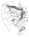
次に、図1を参照すると、本発明によるシート組立体は全体を符号21にて示しており、シート22はシート取付組立体20によって取り付けられていて、シートは、略水平に向いているが、上に凹である弓形のシート経路に沿って動くことができ、弓形のシート経路の少なくともひとつの中心は、シート22上に座る人物の重心の近くに配置されている。図1及び図2に示した矢印35は、上に凹である弓形経路に従ったシートの運動を示していて、図1及び図2に示した中心線60は、重心CGつまりシート上に座る人物(図2)の重心の近くに配置されるべき、経路35の曲率中心を示している。経路35に沿った動きをシート22に与えるための取付組立体20の構造は、それ自体新規ではなく、そうした運動については上に述べた本出願人の米国特許に開示されているので、それらの特許権をここで参照によって引用する。図2に示すように、下部脚部長枕クッション57は、エアバッグの形態を採り得るもので、乗り物が衝突したときに荷重を支えるように貢献し、拘束ベルトの固定点74はシート取付組立体に固定され、固定の位置は、実質的に、体の重心の下方かつ後方に位置していて、使用中の衝突時において腰部ベルトの傾斜方向を変化させる。固定点74は、ベルトが床に固定される場合には、腰部ベルトを経由させるローラーループの形態を採り得る。
Referring now to FIG. 1, the seat assembly according to the present invention is indicated generally at 21 and the
可動なシート22は、有利には、図4に最も良く示されているように、上に凹であるシートパン24を備えて形成される。可動なシートパン24は、静止した取付組立体ないしシェル26に、受け入れられ、入れ子にされる。シートパン24の前部には、上方へ傾いた沈み込み防止拘束部材49を設けるのが有利である。平坦な拘束部材49の前端は、有利には、シートパン24の上方へ延びた唇部を具備し、シートパンフレームの残余の部分と組み合わされて、バケット形のシート支持構造を提供し、これを覆うように、図1に模式的に示したクッション48が延設される。拘束部材49は、図2に力のベクトル14を示すように、正面衝突した場合に、シート上の人物が、前方へ滑ったり、沈み込んだりすることに抵抗する。従って、拘束面49は、シートの運動35と関連して、沈み込みに抵抗するように働く。
The
シートパン24における側壁24aの底部には、一対の曲線状の案内軌道28(図1、図4、及び図5)が設けられ、スライダ27(図5に最良に示される)と協働する。変形例としては、スライダに代えて、ローラー要素(図示せず)を用いても良い。スライダ27は、低摩擦素材から作られており、ボルト27a又はその他の固定具によって、床面取付部材42(図2及び図4)に取り付けられ、この部材は、乗り物の床面45に結合された、シートの前後位置決め軌道40に支持又は固定されている。軌道28は、シートパン24と一体的に形成され、または、図9Aに示すように、案内軌道ないしチャネル140に別個に取り付けられる。
A pair of curvilinear guide tracks 28 (FIGS. 1, 4 and 5) are provided at the bottom of the
従って、シートパン24によって支えられた弓形の軌道28は、乗り物の床面に対して固定された、静止スライダないしガイド部材27に対して、パン24を弓形に運動させることが理解されよう。部品を逆にして、スライダ(又はローラー)をシートパンによって支持し、弓形の軌道を、シート取付組立体20における調整軌道40又は取付部材42に支持させることも可能であることを理解されたい。
Thus, it will be appreciated that the
シートを拘束している横梁34(図4)は、シート22がスライダ27から離れることを防ぐと共に、シートの動きをチャネルの弓形経路に制限する。横梁34は、両端部に取り付けられたパッド103を有し、これらのパッドはスライダ27とは反対側において、弓形の軌道28に対して摺動係合し、シートの動きを許容しつつ、パッドとスライダとの間にシートパン24を支持する。横梁34は、圧縮バネ100で下方へ付勢されつつ、カム102のカム面118(図5に最良に示される)によって所定位置に保持される。カム102はロッド104に固定され、ロッドにはハンドル46がしっかりと取り付けられている。図4において、ボルト101はバネ100を保持していて、ボルトの下端はブラケット111に螺入され、ブラケットは、図5に示すように、固定具又は溶接によって、支持手段26に固定されている。
The transverse beam 34 (FIG. 4) restraining the sheet prevents the
ユーザが、弓形の動きに対して、所望の位置に選択的にシート22をロックできるために、シートロック組立体が設けられる。シートロック組立体は、ハンドル46を具備していて、ハンドルを図5における破線で示した位置へ捻ると、カムの下側の面119が上を向くように、カム102が位置決めされる。これによって、横梁34に対してクリアランスが設けられ、バネ100は摩擦パッド103を押し下げて、パッド103に対して弓形のチャネル28を減速させ又は停止させる。矢印116は、バネ100によってチャネルないし軌道28に働く、パッド103のバネ付勢力を示している。パッド103が作られている材料の摩擦係数は、通常の運転時にあってはシートの運動を制御できるだけ充分に大きく、既知のしきい値を越える衝突の衝撃を受けたときには(例えば1〜5gを越える加速度による力)、シートの展開を許容できるだけ充分に小さい。
A seat lock assembly is provided to allow the user to selectively lock the
本発明によるシート組立体は、有利には、図5に最良に示されるように、シートの大腿部長さ及び腰部深さを調節する調節組立体を具備している。ノブ51などの回転可能な調節装置を用いて、ブッシング117を介してパン24の両側に取り付けられた軸106を回転させる。軸106は、スロット107を有し、このスロットは、腰部調節部材ないし調節棒109に設けられた歯108に係合すべく形成されており、腰部調節部材はブラケット110を介してパン24に摺動可能に取り付けられると共に、パン24の上面に摺動可能に設けられたガイドピン110a(図4)によって取り付けられている。棒109は、バックレストのリンク50への結合を提供し、リンクは、ピボット組立体47を中心としてピボットし、もって、バックレストを調節可能にシートに結合する。このように、ノブ51を回転させると、ピボット47及びバックレスト25の下部部分ないし腰部部分は、矢印115に示すように、前後に移動する。この動きによって、シートの前縁から、バックレストフレームにおける腰部領域の下部部分までの距離が調節される。そして、シートパンの長さを制御することによって、腰部支持の深さも制御される。人物の骨盤が前後に押されると、骨盤の上部は、腰部の曲線を増やすように回転する。
The seat assembly according to the present invention advantageously comprises an adjustment assembly for adjusting the thigh length and waist depth of the seat, as best shown in FIG. A rotatable adjustment device such as a
また、シート組立体21は、バックレスト組立体25を具備し、バックレスト組立体は、バックレストフレーム32に取り付けられている。バックレストフレーム32は、シート22の近くにおいて略垂直な向きに延びていて、本発明においては、第1の又は下側のバックレスト部材35は、フレーム組立体32に対して、再び図1に模式的に示されている。
The
図1及び図2に示した実施形態においては、第1のないし下側のバックレスト部材36と、第2のないし上側のバックレスト部材39との、2つのバックレスト部材が存在しているが、図6及び図7に示した実施形態においては、単一のバックレスト部材36だけが使用される。いずれの実施形態にあっても、バックレスト部材の最上部には、ヘッドレスト部材41が取り付けられる。図1及び図2において、ヘッドレスト41は、フレーム部材40によって支持されており、フレーム部材は、上部バックレストフレーム38に取り付けられて、垂直に調節できるが、そのやり方は当業界において周知である。図1及び図2に示した実施形態においては、輪郭部分を示した側部長枕37は、リクライニングフレーム32にかぶせて取り付けられる。
In the embodiment shown in FIGS. 1 and 2, there are two backrest members, the first or
本発明による改良されたシート組立体においては、バックレスト25はリンク50を介してシートパン24に結合されて、シートパンと共に動く。これを達成するにはいくつかのやり方があるけれども、図1及び図2においては、バックレストフレーム部材23の下部部分18がリンク50を有し、ピボット結合部47においてピボットさせている。リンク50の下端は、前述の如く、棒109、歯108、軸106、及びブッシング117によって、シートパン24に取り付けられている。矢印35にて示すように、シート22が弓形経路に沿って前後に動くと、バックレストフレーム23の下部部分18は、シートの前後の動きに追従する。変形例としては、リンク50はシートパン22に固定又は溶接しても良い。
In the improved seat assembly according to the present invention, the
フレーム23における上部バックレスト部分99は、ピボット部材30によって、摺動部材31に結合されている。スライダ31は、バックレストがリクライニングしていないときには、バックレストリクライニングフレーム32によってチャネル29にしっかり支持されており、矢印35にて示すようにシート22が弓形の前後方向に動くと、下部バックレストフレーム23における上部部分99は、矢印98にて示すように、垂直に延びる方向にガイドされる。図示の通り、ピボット30は、フレーム23の最上部部分99に設けられているけれども、ピボット30を下部部分に移動させても(または、フレーム23が上方へ延びるならばより高く移動させても)、本発明の精神及び教示から逸脱するわけではないことを理解されたい。
The
本発明による可動なバックレスト取付組立体は、正面衝突における安全性を高めるが、特に有利には、人物の頭部が後方に加速されるときの安全性を高める。例えば、乗り物が後部に追突を受けたとき、または、正面衝突に際しては、シート上の人物は後方へのリバウンドを受ける。バックレストの下端をシートと共に動くように取り付け、上端をバックレストフレームによって略垂直な変位に維持した効果は、図2に最良に示される。実線にて示した人物10は、普通に運転しているときのシート組立体21に座った姿勢である。矢印14にて示すように、正面衝突に際しては、人物は、前方へ変位して破線にて示した姿勢10aになって、このとき、上半身と頭部はエアバッグ51のクッションを受け、また、上半身はシートベルト53によって拘束される。シート22は、図2の破線にて示した前方へと移動し、また、下部バックレストクッション36は、同じく図2の破線にて示した前方の位置へと移動する。
The movable backrest mounting assembly according to the invention increases safety in a frontal collision, but particularly advantageously increases safety when the person's head is accelerated backwards. For example, when a vehicle receives a rear-end collision or when a frontal collision occurs, the person on the seat receives a rebound backward. The effect of attaching the lower end of the backrest so as to move with the seat and maintaining the upper end in a substantially vertical displacement by the backrest frame is best shown in FIG. The
力のベクトル15で示したように、後部から追突を受けた場合には、人物は、符号10bの一点鎖線にて示した姿勢へと後退し、このとき、ヘッドレスト41は一点鎖線41にて示した、垂直に高く変位した位置へと動いて頭部により良く係合し、バックレスト25はユーザの背中を支えるべく、最も後方の位置へと移動する。
As indicated by the
従って、正面衝突の状況においては、バックレスト部材36をその下端においてシートと共に動くように結合しておくことで、シートは、沈み込みに抵抗すべく上方位置へと揺動することができ、バックレストは、人物の前方運動の大部分を減速させるようにユーザの背中に追従する。人物の重心を中心としてシート22の前方部分が上昇することで、人物の質量が急減速するとき、人物に加わる応力を最小限にでき、バックレストは、この極めて望ましいシートの弓形運動を妨げることがない。さらに、シート22が前方位置にあるとき、傾いた、沈み込み防止のシートパン部材40とクッション48とが、減速時に、人物をカップに入れるように保持する。
Therefore, in the situation of a frontal collision, by connecting the
後方から追突を受けた状況においては、シートと下部バックレスト部分とは、人物の重心を中心とした動きに逆らって、人物の質量の加速を最小限とし、バックレストを真っ直ぐに伸ばして、ヘッドレスト組立体41を矢印88に沿って上方へ上昇させ、後方へ動く頭部をクッション41によって支持する。バックレストフレーム23の下部部分18とクッション36とはシートと共に移動して、軸線60を中心とするシートの弓形運動に干渉したり、これを阻害することはない。
In situations where a rear-end collision has occurred, the seat and the lower backrest are designed to move the headrest straight, minimizing the acceleration of the mass of the person against the movement centered on the center of gravity of the person. The
乗り物に固定されたシートに座る人物は、背中の支えが減って背骨の腰部曲線は沈降し、リラックスして、たわみ曲線に滑り込む傾向がある。本発明によるシート組立体においては、シートの位置に対するバックレストの位置が、この欠点を修正する。シートのクッションが前方へ移動すると、腰部を支持する領域は、人物の背中の下部に近づいて、シートとバックレストとの間の角度が鋭角になると、背中下部の支えを著しく増加させる。 A person sitting on a seat secured to a vehicle tends to have less back support, the back curve of the spine sinks, relaxes, and slides into the deflection curve. In the seat assembly according to the invention, the position of the backrest relative to the position of the seat corrects this drawback. When the seat cushion moves forward, the region supporting the lumbar region approaches the lower part of the back of the person, and when the angle between the seat and the backrest becomes an acute angle, the support of the lower back is remarkably increased.
シートが、自発的に、または、後部追突を受けて、後方へ回動すると、バックレスト及びヘッドレストが肩部及び頭部に近づいて、サポートを改善する。 When the seat spontaneously or receives a rear rear impact and pivots backward, the backrest and headrest approach the shoulder and head to improve support.
図示の実施形態においては、案内チャネル19は直線状であるけれども、バックレストフレーム23の上端99の運動は、前方に向けてわずかに凹である、弓形の運動にガイドしても良いことを理解されたい。
In the illustrated embodiment, the guide channel 19 is straight, but it is understood that the movement of the
安全性に関して、動的なシートが適切に機能するための重要な観点は、シートの回転中心の位置である。シートの運動中心60は、最も好ましくは、座った人物の重心CGに対して、34mm上方に位置する。多数の衝突試験によって、衝突中の負傷荷重が低減されることが確認された。本発明によるシートは、負傷荷重の低減に著しく貢献し、連邦の標準試験によれば、約30%の低減が得られる(30mphのベルト装着及び非装着のFMVSS208、40mphのベルト装着のオフセット衝突、及び35mphのベルト装着のUS−NCAP)。本発明のシート組立体によって、正面衝突及び後部追突に対して高められた動力学によれば、肢体の負傷を減少させ、いくつかの場合には死亡の見込みを減少させる。
With regard to safety, an important aspect for a dynamic seat to function properly is the position of the center of rotation of the seat. The
本発明における他の重要な特徴は、図7に示したバックレストの動きと、シート/バックレストの減速機能76が一緒になって、または、図8に示した89が正面衝突及び後部追突に対するショックアブソーバ手段を提供することである。 Another important feature of the present invention is that the backrest movement shown in FIG. 7 and the seat / backrest deceleration function 76 are combined, or 89 shown in FIG. It is to provide a shock absorber means.
本発明によるシート組立体は、好ましくは、リクライニング組立体33をさらに具備する。図3は、リクライニング組立体33を示しており、完全にリクライニングした限界では、図1及び図2の位置から後方へ35度傾斜している。リクライニング機構33は、図12及び図6に最良に示されており、上方かつ後方へ延びた、シート組立体取付シェル26のアームと、後部リクライニングフレーム32及び81との間に結合され、これらには、図6に示したバックレストチャネル29又は78が固定されて取り付けられて、可動なバックレストフレーム23及び82から分離され隔てられている。リクライニングのためにリクライニングフレーム32を選択的にロック及び解放する機構は、多数の標準的な形態のうち任意のひとつの形態を採ることができ、図2に示した向きから、図3又は図6に示した向きへと、バックレストフレーム32を後方へ向けて選択的に傾けられる。
The seat assembly according to the present invention preferably further comprises a
図示の通り、部材33aは、弓形に配列された歯33bを有する。このラックないしギア部材33aは、リクライニングフレームによってしっかり支持されている。ハンドル33dを有するピボットアーム33cは、静止したシート取付シェル26に取り付けられる。アーム33cの端部には、ピン33eなどの、少なくともひとつのインターロック部材が支持されて、歯33bに相互係合している。アーム33cは、ピボット33fを中心として上方に回動し、歯33bからピン33eを解放させて、リクライニングフレーム32がピボット33gを中心として取付部材26に対して動けるようにする。リンク33h(図6)は、アーム33iに結合され、横断軸33jにキー付けされ、アーム33cの動きを反対側の組立体に伝達し、シートの反対側にあるラックないしギア33aからピンを解放させる。
As shown, the member 33a has teeth 33b arranged in an arcuate shape. The rack or gear member 33a is firmly supported by the reclining frame. A
図3は、リクライニング位置において、シート組立体21に座った人物について、好ましいリクライニング角度を幾何学的に示しているが、別の角度を採用しても良いことを理解されたい。シート22を上方へリクライニングさせた状態においては、図3に示すように、垂直に対して66度傾斜し、バックレスト25は垂直に対して60度後傾し、上半身と腿との間の角度は126度になって、中立的な姿勢とみなされ、筋肉−骨格系は休息中の平衡状態になる(NSA−NBP)。睡眠姿勢は、航空機のシートなどにおける輸送用途を意図している。図3によれば、シートクッション48は完全な前方位置にあり、バックレスト25及びクッション36は完全にリクライニングしていて、リクライニング姿勢のユーザの背中に、腰部支持を提供している。
Although FIG. 3 geometrically illustrates a preferred reclining angle for a person sitting on the
図3に示したリクライニング状態は、水平に保持されて固定されたシートに比べて、はるかに効果的にユーザの体重をシート及びシートの背もたれに分配させる。リクライニングする背もたれを備え、水平に固定されたシートに座る場合には、ユーザの体重は臀部に集中し、腿がシートから持ち上がって、サポートが失なわれる。ユーザの臀部をクッションに沈み込ませない限り、ユーザはシートの前方へ滑る傾向がある。腰部の曲率もサポートを失なってしまい、不都合である。 The reclining state shown in FIG. 3 distributes the user's weight to the seat and the back of the seat much more effectively than a seat that is held horizontally and fixed. When sitting on a seat that has a reclining backrest and is fixed horizontally, the user's weight is concentrated on the buttocks and the thigh lifts from the seat, losing support. As long as the user's buttocks are not sunk into the cushion, the user tends to slide forward of the seat. The curvature of the waist is also inconvenient because it loses support.
本発明によるシート組立体においては、シートの前縁は腿の下側にて上昇するので、ユーザの体重は、クッション48の領域にわたって、より均一に支持される。バックレストのクッション36は、シートに追従して、腰部領域に望ましい前方への推進力を維持する。
In the seat assembly according to the present invention, the front edge of the seat rises below the thigh, so that the user's weight is supported more evenly over the area of the cushion 48. The
さらに、極めて重要なこととして、シート組立体21は、シートのバックレストクッション組立体をシートの後部から単にリクライニングさせるのに比べて、空間の利用効率を高めることがある。従って、バックレストがピボット点33gを中心としてリクライニングするときのシートの運動中には、シート48は、バックレスト組立体が動くのと同様に、前方へ移動する。また、例えば航空機の用途においては、ヘッドレストが下げられるので、バックレストは、在来のリクライニングシートと同じ程には、後列のシートの空間に侵入しない。
More importantly, the
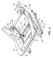
図6及び図7に示した変形例による実施形態のシート組立体においては、単一のバックレスト部材ないしクッション36が用いられており、このバックレスト部材はユーザの肩部にまで延びている。従って、図1及び図2に示した上部バックレスト部材ないしクッション39は、事実上、下部バックレスト部材ないしクッション36と結合される。改変されたバックレストフレーム82も提供される。フレーム82は、シート22と共に動くように、一対のピボット47及び結合リンク50によってリンクされ又は結合され、前述の如く、これらはシートパン24に固定されている。フレーム82は、矢印97に示すように、フレーム82の中央に対していくらか上方にある符号96の箇所にてフレーム82に溶接された、一対の軸30によって、垂直に延びて動くように取り付けられている。軸96は、ローラー又はスライダ組立体79を支持していて、この組立体は、案内チャネル78を昇降する。これにより、可動なバックレストフレーム82は、傾動可能なリクライニングフレーム81から分離される。
In the seat assembly according to the embodiment shown in FIGS. 6 and 7, a single backrest member or cushion 36 is used, and this backrest member extends to the shoulder of the user. Accordingly, the upper backrest member or cushion 39 shown in FIGS. 1 and 2 is effectively combined with the lower backrest member or
チャネル78は、分離した背後のリクライニングフレーム81における上端に近接して固定されている。横梁55は、フレーム81の下端に設けられ、リクライニング機構33は横梁55に固定されている。この組立体は、チャネル78によって形成されたスライド面の位置を、静止したシート組立体支持構造26に対して固定させる。従って、任意に選択されたリクライニングフレームの角度において、バックレストフレーム82は、シート22及びその下端と共に前後に動くことができ、その上端にて矢印80に沿って上下にスライドないしロールする。
The
図6及び図7に示したバックレストは、可動なバックレストフレーム82に固定された、側部長枕を受けるようにデザインされている。図面の簡略化のために図示していないが、リクライニングフレーム81の背面中間部を隠すために、背面カバーが提供される。図6及び図7に示した実施形態においては、バックレストフレーム82には、ヘッドレスト支持部材40が固定され、図7に最良に示されるように、ヘッドレストクッション41はバックレストクッション36と共に移動する。
The backrest shown in FIGS. 6 and 7 is designed to receive a side pillow that is secured to a
また、図6には、シート組立体21のための高さ調節機構が開示されている。電気モータ120を用いて、ロッド121を延ばして、リンク122を回動させる。リンク122は回転軸43に固定されており、回転軸は、高さ調節リンク44を回転させるように結合されている。ピボット組立体45は、シート組立体支持構造26に、リンク44を取り付ける。ロッド121を伸縮させることによって、リンク44は、矢印123の方向に回動する。支持構造アーム26は、矢印124の方向に前後に動かされ、前方の横梁42において、傾斜面上に支持されるが、そのためには、在来のやり方によりボルトとこれに嵌合する前後のスロット孔を用いて(図示せず)、スライド手段26を42に固定する。このように、シート組立体21は、上下に調節することができる。
FIG. 6 discloses a height adjusting mechanism for the
シート22の弓形の運動の範囲は、前方方向には35度で、後方方向には20度である。これらの限界は、シートの用途に応じた必要性を満たすように変更しても良い。
The range of arcuate motion of the
多くの自動車において代表的に見られるように、また、図5、図6、及び図7に示すように、肩部ベルト53などの拘束具が設けられる。ベルト53の上端83は、ローラー組立体95を乗り越えて取り付けられ、標準的なリトラクタ及び/又は荷重リミッタ127によって、可動なバックレストフレーム82の上端に結合されている。ベルト53における腰部部分53aは、シート21の窓側においてユーザの股関節の真下に位置する固定部74によって、シート取付構造26に固定される。ベルト部分53aの反対側の端部は、標準的なバックル120を備え、シート21の反対側に対称的に固定される。固定点74には、プリテンショナ、リトラクタ、及び荷重リミッタ127が据え付けられ、バックレストフレーム組立体の支持構造26に、または、床構造に、または自動車に設けられたピラーに固定される。
As typically seen in many automobiles, and as shown in FIGS. 5, 6, and 7, a restraint such as a
さらに、ベルトの固定部が床45上に配置されるときには、腰部ベルト53aはローラー及びピンを用いて再経由され、固定部74の位置に固定された、好ましくは股関節の真下に配置された連続的なループ固定点を提供し、こうして、衝突時には、ベルトは身体をシートに向けて引き下ろす。より代表的には、衝突時にユーザを引き戻すために、固定点74は、固定されたシート組立体におけるシートの後方に位置するだろう。より代表的には、衝突時にユーザを引き戻すために、固定点74は、固定されたシート組立体におけるシートの後方に位置するだろう。しかしながら、弓形に可動なシートを有する本発明においては、シートがその弓形の経路に沿って動くとき、固定部74はユーザがシートに対して保持されることを保証する。後方に配置された腰部ベルト53aの固定点は、シートの弓形の運動に抵抗するだろうが、これを達成するには、シートの弓形運動を許容するような引き伸ばせるベルト素材を用いる。
Further, when the belt fixing part is arranged on the
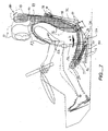
図7には、普通の運転状態における、10度の範囲の自己調節運動が示されている。自発的な姿勢の変化によって脚を伸ばすと、シート組立体には回転が生じる。軸線60を中心とする、かかる回転によって、バックレスト36の高さと角度位置とが変化して、ヘッドレスト41はおよそ50mm上昇する。シート22が後方へ回転すると、バックレストとヘッドレストとは、矢印80に示す如く、頭部を支持するように、曲線的に上昇する。この位置においては、シート上の人物は、自分の頭部をヘッドレストに容易に休ませると共に、視線を路上に向けたまま、快適なバランスに達することができる。このように、脚部や臀部、又は上半身の自発的な運動によって、ただシートの角度を変えるだけで、支持クッション組立体の全体を、直立した姿勢といくらかリクライニングした姿勢との間において調節することができる。
FIG. 7 shows a self-regulating movement in the range of 10 degrees under normal driving conditions. When the legs are extended due to spontaneous posture changes, the seat assembly rotates. Such rotation about the
安定した体の平衡を維持するという目標を満たすことは、バックレスト36が重さによって下方に動くのを防ぐことを伴う。動的な平衡状態を維持することは、図7の符号76及び図8の符号89にて示した運動制御装置によって援助される。運動制御装置76は、シート上のユーザの上半身の重量に加わる重力の引っ張りに逆らって、シート22を付勢してシートをバランスさせるような力を適用する。そうした付勢を得るために圧縮バネ76を用い、圧縮バネは、シートパン24の前縁と床取付組立体42とにおいて、又はシート支持ないし取付シェル26において、取付装置77によって結合される。
Meeting the goal of maintaining a stable body balance involves preventing the
図示していないが、付勢力調節組立体は、例えば、バネ76を徐々に圧縮することによってバネ力を調節するような、カムを備えても良い。カムを異なる位置に設定することで、異なる体格の人物について、平衡点を調節することができる。シート22を後方へ付勢することによって、ユーザが猫背になったり、臀部が前方に滑り出たりする傾向に耐えられる。
Although not shown, the biasing force adjustment assembly may include a cam that adjusts the spring force by gradually compressing the spring 76, for example. By setting the cams at different positions, the equilibrium point can be adjusted for persons with different physiques. By urging the
運動制御装置76は、ショックアブソーバ(図示せず)の形態を採ることができ、シートの減速が既知の力を越えたとき(例えば、2〜5kN以上)、ショックアブソーバに対して臀部が弾性的に変位する。 The motion control device 76 can take the form of a shock absorber (not shown), and when the seat deceleration exceeds a known force (for example, 2-5 kN or more), the buttocks are elastic with respect to the shock absorber. It is displaced to.
また、制御装置76は、圧力シリンダ内にあるピストンの形態を採ることもでき、乗り物のコンピュータ又はその他の拘束具展開装置によって点火タイミングが制御される、爆発装置を備えても良い。従って、電気ソレノイドは、衝突時に、爆発装置を動作ないし点火させて、シートの回転と複合されたバックレストの運動を、ブーストしないし加速させる。 The controller 76 may also take the form of a piston in a pressure cylinder and may include an explosive device whose ignition timing is controlled by a vehicle computer or other restraint deployment device. Thus, the electric solenoid activates or ignites the explosive device in the event of a collision, not boosting or accelerating the backrest movement combined with the rotation of the seat.
変形例としては、運動制御装置76は、普通の運転時には、安楽を得るために、運転者によって制御され、手動スイッチや車載コンピュータによってシートの傾動運動が制御される。 As a modified example, the movement control device 76 is controlled by the driver to obtain comfort during normal driving, and the tilting movement of the seat is controlled by a manual switch or a vehicle-mounted computer.
図8に示した、本発明によるシート組立体は、バンやトラックなどの車両に搭載されており、前列のシート位置は、背の高い、床取付サスペンション手段87を有している。サスペンション組立体87は、路上の隆起や穴をクッションすべく、重量級の車両に使用しても良い。図8に示した後列のシート位置においては、本発明によるシート組立体は、車両の床面45に支持され取り付けられた、脚部86を有するデッキ84に搭載されている。
車両が隆起を乗り越えるとき、車室は上方にジャンプして、シート組立体21の全体を上方へ移動させる。従って、運転者は、実線で示した位置10から、破線で示した位置10aへと移動する。
The seat assembly according to the present invention shown in FIG. 8 is mounted on a vehicle such as a van or a truck, and the seat position in the front row has a floor-mounted suspension means 87 which is tall. The
When the vehicle goes over the bump, the passenger compartment jumps upward and moves the
バックレスト部材36の下端は、矢印90に示す如く、弓形の経路に沿って動き、シートは弓形経路に沿って後方へ動き、クッション36の上端は、矢印88に示す如く、上方へと動く。この運動の間、運転者の身体は、運転者の足を床上又はアクセルペダルの上に載せた状態のままに維持される。
The lower end of the
バックレスト付勢圧縮バネ89は、動的なシートのバランス力と、追加的なサスペンション機能を提供し、シート取付構造26に取り付けられた、シートリクライニングフレームの横部材55と、軸30と略同じレベルにある、バックレストフレーム82との間に提供される。バネ89は、下向きの体動に対して組立体21のバランスをとる。
The backrest biasing
従って、総合的な体の軌道は、2つの構造によって影響される。第1は、矢印101に示すように変位するサスペンション87であり、第2は、矢印88、90、及び91にて示した本発明のシート組立体による運動である。このように、シート組立体21は、姿勢の変化に際して、及び/又は、垂直又は水平な激しい加速度の発生に際して、体のサポートを調節する。
Thus, the overall body trajectory is affected by two structures. The first is the
図示していないが、ノブの回転やモータ手段を使用して、シートの運動を引き起こすために、ローラー要素をその軸線を中心として選択的に回転させ、それにより、シートの軌道28を新たな位置に回転させても良い。
Although not shown, the rotation of the knob or motor means is used to selectively rotate the roller element about its axis to cause movement of the sheet, thereby causing the
図8に示したシート組立体は、図1乃至図5に示したものと実質的に同一に構成されている。サスペンション87と床面取付84,86とに加え、スライダに代えて、ローラー27が、案内軌道28上におけるシート22の弓形運動をガイドしている。さらに、シート36は、図1、図6、及び図7に示すように構成された、リクライニングフレーム81又は32を備えた単一の部材であり、図8の後列シートは、車両の後壁ないしパネル102に取り付けられている。
The seat assembly shown in FIG. 8 is configured substantially the same as that shown in FIGS. In addition to the
次に、図9A乃至図9Cを参照すると、図示の実施形態においては、弓形の案内軌道140が別個の部材として形成されており、それらは、固定具、溶接、又はその他の手段によって、シートパン24の側壁24aの底部付近にてシートパンに固定されている。支持案内軌道140には、弓形部材141が取り付けられ、弓形部材は取付部材42に固定されている。弓形のシート軌道140は、図9B及び図9Cに最良に示されるように、複数のボールベアリング又はローラーベアリング142によって、弓形部材141に支持されている。
Referring now to FIGS. 9A-9C, in the illustrated embodiment, an
案内軌道装置に加えて、図9A乃至図9Cは、解放可能なシートのロック又は止め具130を示していて、2gといった前方への急減速などの慣性しきい値を越えない限り、弓形支持体141上の固定された位置に軌道140を保持する。
In addition to the guide track device, FIGS. 9A-9C show a releasable seat lock or stop 130, as long as the inertia threshold, such as forward deceleration, such as 2g, is not exceeded. The
図9B及び図9Cの拡大断面図に示すように、慣性ロック/解放組立体130は、垂直に往復動するピン132を備えて形成され、ピンは、ブッシングないしスリーブ134の内側に取り付けられており、尖った端部ないしテーパの付いた端部128を形成され、この端部は、複数の孔ないし嵌合ポケット139のうち選択されたひとつに嵌入するような寸法になっている。図9Bにおいて、ピン132が引っ込んだときの位置は、実線で示されてハッチングが施されていて、テーパの付いた端部128が孔139に嵌入した位置は破線にて示している。実線で示した位置と破線で示した位置との間におけるピン132の動きは、ハンドル131によって手動式に行われる。
As shown in the enlarged cross-sectional views of FIGS. 9B and 9C, the inertia lock /
図9Cの矢印145にて示すように、ハンドル131を用いて、ブッシング136の内側にある軸137を回転させる。ピン132は、ピン132の切欠103に嵌入するような二股状の端部を有してなる指部部材146によって、押し上げられ又は押し下げられる。ハンドル131を回転させると、軸137が回転して、指部146が傾斜する。指部146は、軸137を貫通するボア孔に取り付けられて、固定ネジ146aによって所定位置に保持される。指部146の外側端部には、円筒形のカップ135が形成されている。円筒形のカップ135の内部には、バネ荷重式のボール144が設けられて、ハウジング138の側部に当接している。このように、ピン132がポケット139に係合すると、バネ143が指部146を上方へ付勢して、従って、軌道140のポケット139にピン132が嵌入する。図示してはいないが、曲線状の軌道28を使用することができる。止め具ピンは、上方へ付勢されたまま残されて、横梁42上の支持部材141にシート22をロックするが、シート組立体支持構造26は図面を明瞭にするために不図示とした。
As shown by the
図9Cのベクトル矢印104に示すように、前後いずれかの方向に軌道140とシート22が加速されると、シート22は解放されて弓形運動が生じる。従って、正面衝突や後部追突に際しては、孔ないしポケット139を形成している軌道140がピン132の傾斜面128を前方又は後方に押して、ピン132は、図9Bに実線にて示した位置又は図9Cに破線にて示した位置へと押し込まれる。ボール144が、指部146の傾動範囲における中心線を越えると、バネ143は指部を下げるように、ないし、ピンを引っ込める位置へ向けて付勢するようになる。
As indicated by the
シートの動きを手動で解放するためには、ハンドル131を反時計まわり方向に回すことで、指部146を図9Cにおける反時計まわり方向に傾動させ、ピン132を下方位置へと変位させる。円筒形のカップ135は矢印145に沿って上向きにおよそ30度回動し、ピン132を下方へ付勢し、充分なクリアランスをもって、軌道140の開口部139から端部128を変位させ、軌道とシートとに弓形の運動を許容する。
In order to manually release the movement of the seat, the
図10A及び図10Cは、3つの他の実施形態による、可動なバックレストフレームと、本発明のシート組立体における、別個のリクライニングフレームとを示した斜視図である。 10A and 10C are perspective views illustrating a movable backrest frame and a separate reclining frame in the seat assembly of the present invention, according to three other embodiments.
図10Aは、一体型の可動なバックレストフレーム150であって、模式的に示された比較的静止した側部長枕56の間において、本発明に従って移動する。長枕56は、リクライニングフレーム32に固定されている。このように、側部長枕56と、バックレストの背面カバー、又はシートベルト(図面を簡略化するため不図示)は、バックレストフレーム150の運動中に、リクライニング機構33にしっかりと取り付けられて維持される。
FIG. 10A is an integral
図10Bは、2つの部品を有するシート組立体であって、下部バックレストフレーム部分151と、これに取り付けられる上部バックレストフレーム部分152とを備えてなる、全幅のバックレストフレーム組立体である。ピボットピン30は、下部バックレストフレーム151をスライダ部材31に結合している。結合プレート153には、上部バックレストフレーム部分152が固定され、このフレーム部分はスライダ31と共に動くように、スライダに取り付けられている。従って、フレーム部分152は、嵌合する案内チャネル78に沿って昇降する。チャネル78は、別個のリクライニングフレーム部材81に構造的に固定され、ピボット組立体47は、図1乃至図5に関連して述べたように、シートに結合されている。バックレストフレーム151。
FIG. 10B is a full width backrest frame assembly having a two-part seat assembly comprising a lower backrest frame portion 151 and an upper
図10Cに示したバックレスト組立体は、リクライニングフレーム部材81を備えていて、その底部付近には横梁55が設けられている。リクライニング機構33は案内チャネル78を支持しており、図1乃至図5に関連させて説明したのと同様に、この案内チャネルはシート取付組立体(図示せず)に構造的に固定される。結合プレート153は、上部バックレストフレーム部分152をリクライニングフレーム81に結合する。ピボット47は、(リンク50などの)リンクによって、シートパンに結合されており、フレーム151はシートに追従して弓形経路を前後に移動する。バックレストフレーム151の上端は、ピボット30によって、ローラー79に結合されており、摺動チャネル78にガイドされて垂直に動く。
The backrest assembly shown in FIG. 10C includes a
可動な腰部支持フレーム部材151の上端には、ピン154によって、管状部材155が結合されており、管状部材は、ブッシング156を通って延びて、上部バックレストフレーム部分152に固定されている。フレームの付近152の上端へのブッシング156による結合は、好ましくは、フレキシブルになっていて、弓形のシートの運動に起因する、部材155のあらゆる整列誤差を許容する。ヘッドレスト41は、管状部材155の内部に入子式にされたフレーム部材40によって支持されていて、ヘッドレストの高さを調節可能にしている。このように、上部バックレストフレーム部分152は、リクライニングフレーム部材81に固定されたまま維持され、腰部フレーム部材151は、下端においてはシートパンの弓形の運動に、上端においては往復運動に、追従するように形成されている。
A
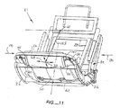
図11は、本発明の他の実施形態によるシート組立体21であって、シートに横方向の動きを実現するために、シート取付組立体によってシートを球形に支持している。乗り物は、もちろん、横方向及び/又はオフセット衝突を受け、それは、乗り物の乗客に急激な加速度を生じさせる。従って、乗り物には、複雑で複合的な力のベクトルが加わり、ベクトルは必ずしも、上述した本発明の実施形態による、前後のシート運動に整列されているわけではない。図11に示したシート組立体は、正面衝突及び後部追突と同じく、横斜め及びオフセットした衝突(軸線方向に整列していない真正面でない衝突。)における衝撃及び振動を少なくとも部分的に適合ないし低減するような、シートの動きを可能にするやり方にて構築されている。
FIG. 11 shows a
図11に示した実施形態においては、球形の表面を有する案内軌道161がシートパン24に設けられ、これに合致する球形の支持表面162がシート取付構造26に設けられる。図11に示した実施形態においては、支持表面162は、構造的な堅固さのために、中間面160によって結合されている。表面160は、球形の表面として示しているが、球形である支持面同士の間は、円筒形や、弓形、又は不連続な補強構造160を採用することも出来、というのは、表面160は直接には支持軌道161やシートパン24を支えることがないためである。軌道161は、支持表面162に合致して摺動接触し、軌道161と表面162とは好ましくは実質的に同一の曲率半径165を有すると共に、回転軸線の中心60は、シートに座る人物の体重の中心近くに配置されている。従って、シート24は、矢印35に示す如く、前後方向に可動に支持されると共に、矢印163に示す如く横方向に可動に支持され、前後方向と横方向とを組み合わせた様々な方向に可動になっている。
In the embodiment shown in FIG. 11, a
本発明における他の実施形態の場合と同様に、可動なバックレストフレーム23は、その下端をシートパンと共に動くようにシートパン24に結合される一方、上端99は、シートの運動に応じて垂直に往復動すべく、符号30にて、別個のリクライニングフレーム32に結合される。シートパン24は球形の経路に沿って動くので、リンク50は、単なるピボット結合具47よりも、むしろ球体の結合具によって、バックレストフレーム23に結合させることが好ましい。符号47の箇所における球体の結合具は、ベクトル170のような横方向の衝撃力ベクトルの下で球形のシート運動を充分に妨げるのに充分なやり方で、バックレストフレーム23がねじれる傾向を低減する。いくらかの弾性的なフレームのねじれを受けても、シートの性能に著しく影響することはなく、両側にあるピボット30の高さのいくらかの違いは前記フレームのねじれによって適合され再現する。
As with the other embodiments of the present invention, the
図11の実施形態が意図している利点は、負傷を起こす力を減少させ、NHTSA によって提案されているようなオフセット正面衝突、及び/又は、側面衝突において、安全性を改善することである。さらに、オフロード車両やトラクターなどの産業用設備に適用される場合には、図11に示したシート組立体21は、一定したピッチング及びローリングによる健康危険を低減させる、横方向のサスペンションとして作用する。
The intended benefits of the embodiment of FIG. 11 are to reduce the forces causing injury and to improve safety in offset frontal and / or side collisions as proposed by NHTSA. Furthermore, when applied to industrial equipment such as off-road vehicles and tractors, the
本発明による可動なバックレストフレーム組立体は、シート取付構造に採用することができ、概略の連続した半径は、ユーザの重心の近くにある曲率中心のまわりにある。従って、図12A及び図12Bに示した2つの代替的なシート取付構造は、本発明による可動なバックレスト組立体を備えている。 The movable backrest frame assembly according to the present invention can be employed in a seat mounting structure, where the approximate continuous radius is around the center of curvature near the user's center of gravity. Accordingly, the two alternative seat mounting structures shown in FIGS. 12A and 12B include a movable backrest assembly according to the present invention.
図12Aにおいて、シート22の弓形の前後運動35は、一対のピボットアームないしリンクの使用によって得られている。対をなす前方のアームないしリンク175と、対をなす後方のリンク176とが設けられて、軸組立体177及び178を中心としてピボットする。軸ないしピボット177は、床取付レール40に、または、組立体取付手段26に取り付けられ、一方、上側の軸ないしピボット178はシートパン24に取り付けられている。リンク175及び176は、経路179を中心として前方へ、また、経路180を中心として後方へ、回動する。このように、たとえリンクの運動経路が軸177を中心とした下向きの弓形経路であるとしても、シート22は、上向きに傾いた経路35に沿って動き、かかる経路は、シート22に座った人物の重心の近くに配置された回転軸線60を有する。従って、シート22の上面は、回転軸線60を中心とする弓形に沿って動く。他の実施形態に関して前述したように、バックレスト部材36は、リンク50とピボット組立体47を介して、シートパン24に結合される。
In FIG. 12A, the arcuate back-and-forth
図12Bにおいて、シート組立体取付構造26には、案内スロット184及び185が設けられ、スロットは、矢印188及び190に示すような移動経路に沿って動けるように、ロール又はスライド要素186及び189を許容すべく形成されている。シートパン24は、三角形部材200によって前部ロール要素189に取り付けられ、不図示の軸取付ブッシングによって後部ロール要素186に直接取り付けられている。シートパンの後部は、ガイド184に沿って下向きに移動し、一方、シートの前部は、ガイド185に沿って主として前向き上方へ移動する。このように、シート22の表面は、軸線60を中心とする、実質的に弓形に沿って移動する。
In FIG. 12B, the seat
再言すれば、バックレストクッション36の運動は、リンク50とピボット47のために、下端においてシートの運動に追従する。バックレストクッション36の上端は、矢印98にて示すように、符号30の箇所からスライダ31へとピボットする。このように、本発明におけるシートとバックレストとの組み合わされた運動は、変形例によるシートパンの運動機構によっても実現することができる。
In other words, the movement of the
Claims (72)
(a)シートと、
(b)シートを略水平な向きに取り付けるシート取付組立体であって、上に凹である弓形のシート経路に沿ってシートが動けるようにして、弓形のシート経路における曲率半径のひとつの中心は、シート上に座る人物の重心の近くに配置されているような、上記シート取付組立体と、
(c)シート取付組立体の近くに略垂直に延設されるバックレスト部材を具備してなるバックレスト組立体であって、バックレスト部材は、垂直に延びる方向に動くようにバックレスト組立体に取り付けられた上部バックレスト部分と、シートに対して可動に結合された下部バックレスト部分とを有しているバックレスト組立体と、
を備えていることを特徴とするシート組立体。 A seat assembly, the seat assembly comprising:
(A) a sheet;
(B) a seat mounting assembly for mounting the seat in a generally horizontal orientation, such that the seat can move along an arcuate seat path that is concave upward, and one center of curvature radius in the arcuate seat path is A seat mounting assembly as described above, disposed near the center of gravity of a person sitting on the seat;
(C) A backrest assembly comprising a backrest member extending substantially vertically near the seat mounting assembly, wherein the backrest member moves in a vertically extending direction. A backrest assembly having an upper backrest portion attached to the seat and a lower backrest portion movably coupled to the seat;
A seat assembly comprising:
バックレストフレームにおける上部フレーム部分は、垂直に延びる動きをガイドするようにバックレスト組立体に結合され、
バックレストフレームにおける下部フレーム部分は、シートに対して可動に結合されている請求項1に記載のシート組立体。 The backrest member comprises a backrest frame,
The upper frame portion of the backrest frame is coupled to the backrest assembly to guide the vertically extending movement,
The seat assembly according to claim 1, wherein a lower frame portion of the backrest frame is movably coupled to the seat.
バックレストフレームは、スライダ部材にピボット式に結合され、
バックレスト組立体は、一対の案内チャネルを具備し、
スライダ部材は案内チャネルに摺動可能に取り付けられている請求項2に記載のシート組立体。 In the seat assembly,
The backrest frame is pivotally coupled to the slider member,
The backrest assembly comprises a pair of guide channels,
The seat assembly according to claim 2, wherein the slider member is slidably attached to the guide channel.
回転可能な調節装置は、ブッシングによってシートに取り付けられた回転可能な軸であって、少なくともひとつの形成されたスロットを有し、複数の歯のひとつの歯を受け入れ、手で握れるノブを有している請求項20に記載のシート組立体。 The waist adjustment member is a rod-shaped member formed with a plurality of teeth,
The rotatable adjustment device is a rotatable shaft attached to the seat by a bushing, has at least one formed slot, has a knob that accepts one tooth of a plurality of teeth and can be gripped by hand The seat assembly according to claim 20.
シートの一部分と係合する向きに、パッドをシート取付組立体に対して付勢すべく形成されたバネ付勢部材と、
シート取付組立体に取り付けられたカムであって、バネ付勢部材に抗して、シートとの係合からパッドを遠ざけるように形成された上記カムと、
シート組立体のユーザによって選択的に操作されるべく形成及び結合されたカムのアクチュータと、
を備えている請求項23に記載のシート組立体。 The friction member is provided by a pad;
A spring biasing member configured to bias the pad against the seat mounting assembly in a direction to engage a portion of the seat;
A cam attached to the seat mounting assembly, wherein the cam is configured to move the pad away from engagement with the seat against a spring biasing member;
A cam actuator formed and coupled to be selectively operated by a user of the seat assembly;
24. A seat assembly according to claim 23.
慣性ロック組立体は、前記開口部に挿入される可動なピン寸法と、ピン受け入れ構造部に選択的にピンを出し入れする組立体と、を備えていることを特徴とする請求項40に記載のシート組立体。 The seat has at least one arcuate track having pin receiving structures in the front-rear direction spaced apart;
41. The inertia lock assembly of claim 40, comprising a dimension of a movable pin inserted into the opening and an assembly for selectively inserting and removing the pin into and from the pin receiving structure. Seat assembly.
シート組立体に働く慣性が所定のレベルを越えたとき、ピンをピン受け入れ構造部から自動的に外すように、ピンとピン受け入れ構造部とが協働して形成されている請求項41に記載のシート組立体。 The pin is resiliently biased to engage the pin receiving structure;
42. The pin and pin receiving structure are cooperatively formed to automatically remove the pin from the pin receiving structure when the inertia acting on the seat assembly exceeds a predetermined level. Seat assembly.
(a)シートと、
(b)シートを略水平な向きに取り付けるシート取付組立体であって、上に凹である弓形のシート経路に沿ってシートが動けるようにして、弓形のシート経路における曲率半径の中心は、シート上に座る人物の重心の近くに配置されているような、上記シート取付組立体と、
(c)略垂直に延設されたバックレストを具備してなるバックレスト組立体であって、バックレストは、シートに可動に結合された下部腰部部分と、バックレスト組立体における残余の部分に可動にガイドされて結合された上部腰部部分とを有する下部バックレスト部材と、下部バックレスト部材の上方に取り付けられた上部バックレスト部材であって、バックレスト組立体における残余の部分に可動に取り付けられ、下部バックレストと共に動くように下部バックレストに結合された、上部バックレスト部材とを備えているような、上記バックレスト組立体と、
を備えていることを特徴とするシート組立体。 A seat assembly, the seat assembly comprising:
(A) a sheet;
(B) a seat mounting assembly for mounting the seat in a substantially horizontal orientation so that the seat can move along an arcuate seat path that is concave upward; the center of curvature radius in the arcuate seat path is the seat The seat mounting assembly as described above, located near the center of gravity of the person sitting on top,
(C) A backrest assembly comprising a backrest extending substantially vertically, wherein the backrest is connected to a lower waist portion movably coupled to the seat and a remaining portion of the backrest assembly. A lower backrest member having an upper waist portion that is movably guided and joined, and an upper backrest member that is mounted above the lower backrest member and is movably attached to the remaining portion of the backrest assembly Said backrest assembly, comprising an upper backrest member coupled to said lower backrest for movement with said lower backrest;
A seat assembly comprising:
バックレストフレームの背面には摺動可動部材が取り付けられている請求項50に記載のシート組立体。 The guide channel is arranged on the inner side of both sides of the lower backrest member,
51. The seat assembly according to claim 50, wherein a sliding movable member is attached to the back surface of the backrest frame.
上部バックレスト部材は、リクライニングフレームに固定され、
ヘッドレストは、下部バックレスト部材と共に動くように下部バックレスト部材に結合されている請求項44に記載のシート組立体。 The lower backrest member is pivotally coupled to the seat and pivotally coupled to the backrest assembly to displace vertically when the seat moves in an arcuate manner,
The upper backrest member is fixed to the reclining frame,
45. The seat assembly of claim 44, wherein the headrest is coupled to the lower backrest member for movement with the lower backrest member.
(a)シートと、
(b)シートを略水平な向きに取り付けるシート取付組立体であって、シートが、前後方向と横方向と2つの方向の間の斜めの方向とに動けるような、上記シート取付組立体と、
を備えていることを特徴とするシート組立体。 A seat assembly, the seat assembly comprising:
(A) a sheet;
(B) a seat mounting assembly for mounting the seat in a substantially horizontal orientation, wherein the seat is movable in a front-rear direction, a lateral direction, and an oblique direction between the two directions;
A seat assembly comprising:
略水平な向きにおいて、上に凹である弓形の経路に沿って動けるように、シートを取り付ける段階と、
シートに座ったユーザの背中を支えるべく、略垂直な向きにおいて、シートの近くにバックレストを取り付ける段階と、
シートの動きと共にバックレストの下部部分が動くように、バックレストの下部部分をシートに結合させる段階と、
バックレストの下部部分の動きに応答して、垂直に延びる動きをするように、バックレストの上部部分を取り付ける段階と、
を備えていることを特徴とする方法。 A method for providing a seat assembly, the method comprising:
Attaching the seat so that it can move along an arcuate path that is concave upward in a generally horizontal orientation;
Attaching a backrest near the seat in a substantially vertical orientation to support the back of the user sitting on the seat;
Joining the lower part of the backrest to the seat so that the lower part of the backrest moves with the movement of the seat;
Attaching the upper portion of the backrest to move vertically extending in response to the movement of the lower portion of the backrest;
A method characterized by comprising:
最初に指名したバックレスト部材と共に垂直に動けるように、第2のバックレストを結合する段階と、
を備えている請求項66に記載の方法。 Attach a second backrest above the first nominated backrest so that it can move in a vertically extending direction, the first nominated backrest is formed to support the user's waist region, Two backrests are formed to support the upper part of the user's back;
Coupling a second backrest to move vertically with the first nominated backrest member;
68. The method of claim 66, comprising:
乗り物に搭載された前記動きは、正面衝突、後部追突、又は斜めのオフセット衝突のうちのひとつにおいて、ユーザが受ける負傷荷重を減少させるために使用される、
ことを特徴とする請求項66に記載の方法。 In said method,
The movement mounted on the vehicle is used to reduce the injury load experienced by the user in one of a frontal collision, a rear-end collision, or an oblique offset collision.
68. The method of claim 66.
Applications Claiming Priority (2)
| Application Number | Priority Date | Filing Date | Title |
|---|---|---|---|
| US10/836,964 US7780230B2 (en) | 2004-04-30 | 2004-04-30 | Seat assembly with movable seat and backrest and method |
| PCT/US2005/015057 WO2005108158A2 (en) | 2004-04-30 | 2005-05-02 | Seat assembly with movable seat and backrest and method |
Publications (2)
| Publication Number | Publication Date |
|---|---|
| JP2007536143A true JP2007536143A (en) | 2007-12-13 |
| JP2007536143A5 JP2007536143A5 (en) | 2008-06-26 |
Family
ID=35186333
Family Applications (1)
| Application Number | Title | Priority Date | Filing Date |
|---|---|---|---|
| JP2007511063A Pending JP2007536143A (en) | 2004-04-30 | 2005-05-02 | Seat assembly and method with movable seat and backrest |
Country Status (3)
| Country | Link |
|---|---|
| US (1) | US7780230B2 (en) |
| JP (1) | JP2007536143A (en) |
| WO (1) | WO2005108158A2 (en) |
Cited By (1)
| Publication number | Priority date | Publication date | Assignee | Title |
|---|---|---|---|---|
| KR102153216B1 (en) * | 2019-03-13 | 2020-09-07 | 현대자동차주식회사 | Multi-position seat for vehicle |
Families Citing this family (74)
| Publication number | Priority date | Publication date | Assignee | Title |
|---|---|---|---|---|
| US9248762B2 (en) * | 2001-04-02 | 2016-02-02 | Arjuna Indraeswaran Rajasingham | Vehicle occupant support |
| US7090293B2 (en) * | 2004-05-26 | 2006-08-15 | Lear Corporation | Automotive seat assembly with improved side impact rigidity |
| US7708313B2 (en) | 2005-09-01 | 2010-05-04 | International Automotive Components Group North America, Inc. | Plastic basket countermeasure for door side impact |
| JP4290701B2 (en) * | 2006-01-13 | 2009-07-08 | テイ・エス テック株式会社 | Vehicle seat |
| US8240758B2 (en) * | 2006-03-27 | 2012-08-14 | Nissan North America, Inc. | Deformable seat pan for a tiltable vehicle seat |
| JP4731422B2 (en) * | 2006-08-01 | 2011-07-27 | 三洋電機株式会社 | Chair type massage machine |
| JP4731439B2 (en) * | 2006-09-29 | 2011-07-27 | 三洋電機株式会社 | Chair type massage machine |
| US8616641B2 (en) | 2006-10-04 | 2013-12-31 | Access Enterprise, Llc | Therapeutic back support and stabilization |
| US10842280B2 (en) | 2006-10-04 | 2020-11-24 | Access Enterprise, Llc | Therapeutic back support and stabilization |
| US8662586B2 (en) * | 2006-10-10 | 2014-03-04 | Hector Serber | Dynamically balanced seat assembly having independently and arcuately movable backrest and method |
| US20080088166A1 (en) * | 2006-10-16 | 2008-04-17 | Gardiner Richard J | Aircraft seat |
| WO2008060144A1 (en) * | 2006-11-14 | 2008-05-22 | Chard Safety B.V. | A deceleration responsive vehicle seat |
| US7527334B2 (en) * | 2007-06-18 | 2009-05-05 | Ford Global Technologies, Llc | Automotive seat reclining system |
| US7677640B2 (en) * | 2008-05-23 | 2010-03-16 | Nissan Technical Center North America, Inc. | Panel assembly for a vehicle |
| BRPI0913467B1 (en) * | 2008-09-03 | 2019-09-10 | Thorley Ind Llc | baby care appliance and method for controlling a baby care appliance |
| US20100066142A1 (en) * | 2008-09-12 | 2010-03-18 | Ussc Group, Llc | Seat assembly with cushion tilt |
| JP5395457B2 (en) * | 2009-02-25 | 2014-01-22 | テイ・エス テック株式会社 | Vehicle seat |
| DE102009043113A1 (en) * | 2009-09-25 | 2011-03-31 | Daimler Ag | A method of protecting a vehicle occupant in a vehicle seat of a vehicle |
| US8474912B2 (en) * | 2009-10-14 | 2013-07-02 | L & P Property Management Company | Seating arrangement with seat and back rest that adjust together to recline |
| DE102009050903B4 (en) * | 2009-10-27 | 2014-02-13 | Siemens Aktiengesellschaft | vehicle seat |
| DE102010010613A1 (en) * | 2010-03-08 | 2011-09-08 | Volkswagen Ag | Vehicle with a safety belt system |
| US20110258771A1 (en) * | 2010-04-26 | 2011-10-27 | Nuprodx, Inc. | Seat tilt mechanism for chairs used by people with disabilities |
| WO2011156536A2 (en) * | 2010-06-10 | 2011-12-15 | Office Master | Chair with seat depth adjustment and back support |
| US8556346B2 (en) * | 2010-11-01 | 2013-10-15 | Ford Global Technologies, Llc | Vehicle seat with rotating angle adjustment |
| CN103402813B (en) * | 2010-12-17 | 2017-11-21 | 约翰逊控制技术公司 | Second row seat |
| US8336658B2 (en) | 2010-12-22 | 2012-12-25 | Tesla Motors, Inc. | Augmented vehicle seat mount |
| CN102218992B (en) * | 2011-06-14 | 2012-09-05 | 上海延锋江森座椅有限公司 | Stepless regulating structure of seat |
| JP5859265B2 (en) * | 2011-10-05 | 2016-02-10 | 日本発條株式会社 | Vehicle seat |
| US8783771B2 (en) * | 2011-11-21 | 2014-07-22 | Be Aerospace, Inc. | Extendable seat pan assembly with comfort spring |
| US20130220208A1 (en) * | 2012-02-28 | 2013-08-29 | Réjean Boyer | Seat for a watercraft |
| US9168848B2 (en) * | 2013-03-15 | 2015-10-27 | Ford Global Technologies, Llc | Vehicle seating assembly |
| SG11201508202WA (en) * | 2013-04-05 | 2015-11-27 | Singapore Tech Aerospace Ltd | Seat structure for a passenger seat and passenger seat |
| EP2805850B1 (en) * | 2013-05-22 | 2016-02-17 | Tachi-S Co., Ltd. | Vehicle seat |
| CN103303171B (en) * | 2013-06-03 | 2015-06-17 | 吉林大学 | Car seat anti-submarining protection system based on movable seat basin |
| US9527413B1 (en) | 2013-11-12 | 2016-12-27 | The United States Of America As Represented By The Secretary Of The Army | Reclining seat to mitigate the effects of mine blast load on spine and lower leg injuries |
| JP6192221B2 (en) * | 2013-11-18 | 2017-09-06 | 株式会社タチエス | Sheet |
| US9308842B2 (en) * | 2014-02-24 | 2016-04-12 | Ford Global Technologies, Llc | Pyrotechnic fastener seat arrangement for unbelted occupant protection |
| US9193281B2 (en) | 2014-04-17 | 2015-11-24 | Fca Us Llc | Reclining vehicle seat system |
| EP3154818A2 (en) * | 2014-06-10 | 2017-04-19 | Zodiac Seats US LLC | Monocoque and semi-monocoque passenger seats with ergonomic design |
| US9744881B2 (en) * | 2014-08-25 | 2017-08-29 | Ami Industries, Inc. | System and apparatus for decoupling an electro-mechanical actuator from a portion of a linkage |
| DK2997823T3 (en) | 2014-09-19 | 2018-03-19 | Instr Utils De Laboratori Geniul Sl | Method to improve sperm quality in mammals |
| US9821688B2 (en) * | 2014-10-02 | 2017-11-21 | Ford Global Technologies, Llc | Rear seat cushion with H-point articulation |
| US9327624B1 (en) * | 2015-03-10 | 2016-05-03 | King Abdul—Aziz City for Science and Technology | Safety device for vehicle seats |
| US10143308B2 (en) | 2015-07-23 | 2018-12-04 | Herman Miller, Inc. | Seating device |
| KR101762263B1 (en) * | 2015-12-04 | 2017-08-07 | 현대자동차주식회사 | System for controlling a front seat being connected with a head rest and its methods therefor |
| US10232744B2 (en) * | 2016-01-12 | 2019-03-19 | Rockwell Collins, Inc. | Independent translating roller seat |
| US10933787B2 (en) | 2016-08-19 | 2021-03-02 | Adient Luxembourg Holding S.Á R.L. | Head restraint follower |
| JP6718785B2 (en) * | 2016-10-04 | 2020-07-08 | 株式会社タチエス | Vehicle seat |
| US10442327B2 (en) * | 2016-12-23 | 2019-10-15 | Ford Global Technologies, Llc | Seat bottom tension member |
| JP6865591B2 (en) * | 2017-01-18 | 2021-04-28 | 日本発條株式会社 | Vehicle seat |
| WO2018144455A1 (en) * | 2017-01-31 | 2018-08-09 | Next Health, Llc | Systems and methods for powered wheelchair personal transfer |
| CN108451222B (en) * | 2017-02-22 | 2021-08-13 | L & P 产权管理公司 | Integrated lumbar support and head tilt assembly |
| US10376063B2 (en) | 2017-02-22 | 2019-08-13 | L&P Property Management Company | Integrated lumbar and head tilt assembly |
| US10694897B2 (en) * | 2017-03-22 | 2020-06-30 | Andrew J Hart Enterprises Limited | Bath transfer chair |
| CN107161042B (en) * | 2017-06-29 | 2023-06-30 | 长春富维安道拓汽车饰件系统有限公司 | Detachable automobile seat |
| US10583755B2 (en) | 2017-08-02 | 2020-03-10 | Faurecia Automotive Seating, Llc | Recliner for a vehicle seat |
| US10384566B2 (en) * | 2017-08-25 | 2019-08-20 | Ford Global Technologies, Llc | Vehicle seat assembly |
| US10343558B2 (en) * | 2017-10-19 | 2019-07-09 | Nio Usa, Inc. | Fixed structure seat |
| US10513204B2 (en) | 2017-11-13 | 2019-12-24 | Ford Global Technologies, Llc | Seating assembly pivot bracket |
| US10442326B2 (en) | 2017-11-13 | 2019-10-15 | Ford Global Technologies, Llc | Seating assembly with suspension |
| CZ308161B6 (en) * | 2017-11-13 | 2020-01-29 | Karel Sikora | Tilting front vehicle seats restraint system |
| EP3489078B1 (en) * | 2017-11-22 | 2020-08-19 | Adient Engineering and IP GmbH | A vehicle seat |
| US11021255B2 (en) * | 2018-01-30 | 2021-06-01 | Rockwell Collins, Inc. | Work-and-dine aircraft seat with tilt and shift articulation |
| US10611283B2 (en) * | 2018-09-12 | 2020-04-07 | Rockwell Collins, Inc. | Multi-stage seatback extension system |
| GB2579543A (en) * | 2018-11-30 | 2020-07-01 | Jaguar Land Rover Ltd | Seat assembly for a vehicle |
| US10953780B2 (en) * | 2019-01-29 | 2021-03-23 | B/E Aerospace, Inc. | Deployable infill assembly and passenger seat construction |
| US11596232B2 (en) | 2019-04-16 | 2023-03-07 | MillerKnoll, Inc. | Chair for active engagement of user |
| US10821863B1 (en) * | 2019-06-24 | 2020-11-03 | Ford Global Technologies, Llc | Retention member for vehicle seating assembly |
| WO2021021162A1 (en) | 2019-07-31 | 2021-02-04 | Safran Seats Usa Llc | Cradling passenger seat assembly |
| CN111728408B (en) * | 2020-06-09 | 2023-05-02 | 杭州新涵美家居用品有限公司 | Self-adaptive backrest seat |
| KR102448459B1 (en) * | 2020-07-22 | 2022-09-29 | 현대자동차주식회사 | Vehicle seat assembly |
| CN112691022B (en) * | 2020-12-08 | 2023-10-10 | 奥佳华智能健康科技集团股份有限公司 | Chair frame and sauna cabin |
| US11376995B1 (en) | 2021-01-29 | 2022-07-05 | Ford Global Technologies, Llc | Vehicle seating assembly |
| CN113602504B (en) * | 2021-09-23 | 2023-10-27 | 北京安达维尔航空设备有限公司 | Novel multi-functional lightweight anti-crash seat |
Citations (1)
| Publication number | Priority date | Publication date | Assignee | Title |
|---|---|---|---|---|
| JP2002052966A (en) * | 2000-08-10 | 2002-02-19 | Osamu Kato | Structure for relaxing impact of seat at sudden stop of vehicle |
Family Cites Families (16)
| Publication number | Priority date | Publication date | Assignee | Title |
|---|---|---|---|---|
| BE537159A (en) | 1951-06-06 | |||
| US3357736A (en) | 1966-05-17 | 1967-12-12 | John J Mccarthy | Vehicle seat |
| US4650249A (en) | 1984-12-31 | 1987-03-17 | Hector Serber | Ergonomic seating assembly system with front chest support component, pelvic tilt seat component and related attachments |
| US5022707A (en) | 1988-01-07 | 1991-06-11 | Life Force Associates, L.P. | Vehicle safety device |
| JPH0289947U (en) * | 1988-12-28 | 1990-07-17 | ||
| US5244252A (en) | 1990-10-29 | 1993-09-14 | Hector Serber | Seat assembly and method |
| US5558399A (en) | 1994-09-13 | 1996-09-24 | Serber; Hector | Seat and lumbar motion chair, assembly and method |
| US5961073A (en) | 1995-01-11 | 1999-10-05 | The Boeing Company | Reduced head pad seat |
| NL1004551C2 (en) * | 1996-11-18 | 1998-05-19 | Rpi Advanced Technology Group | Chair. |
| US6334648B1 (en) * | 1997-03-21 | 2002-01-01 | Girsberger Holding Ag | Vehicle seat |
| US6106065A (en) * | 1997-10-24 | 2000-08-22 | Reliance Medical Products, Inc. | Examination chair with lifting and tilting mechanism |
| US6030043A (en) | 1997-12-18 | 2000-02-29 | Bertrand Faure Sitztechnik Gmbh & Co. Kg | Motor vehicle seat, in particular back seat |
| DE10011829C2 (en) * | 1999-03-15 | 2002-08-08 | Nhk Spring Co Ltd | Actuator for a vehicle occupant restraint system |
| IT1306152B1 (en) * | 1999-06-02 | 2001-05-30 | Aviointeriors Spa | ARMCHAIR WITH PERFECTED CRADLE MOVEMENT, IN PARTICULAR AIRCRAFT. |
| US6682141B2 (en) | 2001-09-14 | 2004-01-27 | The Boeing Company | Seat assembly having a seat repositioning device and an associated method |
| JP4069688B2 (en) * | 2002-06-11 | 2008-04-02 | トヨタ紡織株式会社 | Seat vertical device |
-
2004
- 2004-04-30 US US10/836,964 patent/US7780230B2/en not_active Expired - Lifetime
-
2005
- 2005-05-02 JP JP2007511063A patent/JP2007536143A/en active Pending
- 2005-05-02 WO PCT/US2005/015057 patent/WO2005108158A2/en active Application Filing
Patent Citations (1)
| Publication number | Priority date | Publication date | Assignee | Title |
|---|---|---|---|---|
| JP2002052966A (en) * | 2000-08-10 | 2002-02-19 | Osamu Kato | Structure for relaxing impact of seat at sudden stop of vehicle |
Cited By (1)
| Publication number | Priority date | Publication date | Assignee | Title |
|---|---|---|---|---|
| KR102153216B1 (en) * | 2019-03-13 | 2020-09-07 | 현대자동차주식회사 | Multi-position seat for vehicle |
Also Published As
| Publication number | Publication date |
|---|---|
| WO2005108158A3 (en) | 2009-04-16 |
| WO2005108158A2 (en) | 2005-11-17 |
| US20050242634A1 (en) | 2005-11-03 |
| US7780230B2 (en) | 2010-08-24 |
Similar Documents
| Publication | Publication Date | Title |
|---|---|---|
| JP2007536143A (en) | Seat assembly and method with movable seat and backrest | |
| US9399415B2 (en) | Seat assembly with movable seat and backrest and method | |
| CN108528284B (en) | Seat back lifting mechanism for a recumbent motor vehicle seat assembly | |
| US5460427A (en) | Seat assembly and method | |
| US6312050B1 (en) | Chair structure | |
| CN108528293B (en) | Mechanism for a recumbent motor vehicle seat assembly | |
| KR20160087854A (en) | Adjustable seat | |
| US10166887B2 (en) | Seatback lift mechanism for a supine motor vehicle seating assembly | |
| US6742838B1 (en) | Multifunction vehicle seat | |
| US8297698B2 (en) | Mechatronic vehicle safety seat | |
| EP0564470B1 (en) | Seat assembly and method | |
| US10744911B2 (en) | Seating assembly with suspension | |
| US20060103211A1 (en) | Seat assembly with inner seat back movable with a seat cushion | |
| JP2021049887A (en) | On-vehicle seat device | |
| EP1612093B1 (en) | Vehicle seat arrangement | |
| US10513204B2 (en) | Seating assembly pivot bracket | |
| EP1612090A1 (en) | Vehicle seat arrangement | |
| EP1612094B1 (en) | Vehicle seat arrangement | |
| JP3419704B2 (en) | Vehicle seat | |
| JP2021160556A (en) | Seat device | |
| KR19980034344U (en) | Car seat | |
| KR19980074403A (en) | Headrests for Car Seats |
Legal Events
| Date | Code | Title | Description |
|---|---|---|---|
| A521 | Written amendment |
Free format text: JAPANESE INTERMEDIATE CODE: A523 Effective date: 20080502 |
|
| A621 | Written request for application examination |
Free format text: JAPANESE INTERMEDIATE CODE: A621 Effective date: 20080502 |
|
| A977 | Report on retrieval |
Free format text: JAPANESE INTERMEDIATE CODE: A971007 Effective date: 20100930 |
|
| A131 | Notification of reasons for refusal |
Free format text: JAPANESE INTERMEDIATE CODE: A131 Effective date: 20101012 |
|
| A601 | Written request for extension of time |
Free format text: JAPANESE INTERMEDIATE CODE: A601 Effective date: 20110112 |
|
| A602 | Written permission of extension of time |
Free format text: JAPANESE INTERMEDIATE CODE: A602 Effective date: 20110119 |
|
| A02 | Decision of refusal |
Free format text: JAPANESE INTERMEDIATE CODE: A02 Effective date: 20110704 |