JP2007530196A - Fire extinguishing method, fire extinguishing device, and fire extinguishing means - Google Patents
Fire extinguishing method, fire extinguishing device, and fire extinguishing means Download PDFInfo
- Publication number
- JP2007530196A JP2007530196A JP2007505569A JP2007505569A JP2007530196A JP 2007530196 A JP2007530196 A JP 2007530196A JP 2007505569 A JP2007505569 A JP 2007505569A JP 2007505569 A JP2007505569 A JP 2007505569A JP 2007530196 A JP2007530196 A JP 2007530196A
- Authority
- JP
- Japan
- Prior art keywords
- fire extinguishing
- fire
- hose
- pipe
- medium
- Prior art date
- Legal status (The legal status is an assumption and is not a legal conclusion. Google has not performed a legal analysis and makes no representation as to the accuracy of the status listed.)
- Withdrawn
Links
Images


Classifications
-
- A—HUMAN NECESSITIES
- A62—LIFE-SAVING; FIRE-FIGHTING
- A62C—FIRE-FIGHTING
- A62C3/00—Fire prevention, containment or extinguishing specially adapted for particular objects or places
- A62C3/16—Fire prevention, containment or extinguishing specially adapted for particular objects or places in electrical installations, e.g. cableways
-
- A—HUMAN NECESSITIES
- A62—LIFE-SAVING; FIRE-FIGHTING
- A62C—FIRE-FIGHTING
- A62C35/00—Permanently-installed equipment
- A62C35/02—Permanently-installed equipment with containers for delivering the extinguishing substance
- A62C35/10—Containers destroyed or opened by flames or heat
Landscapes
- Health & Medical Sciences (AREA)
- Public Health (AREA)
- Business, Economics & Management (AREA)
- Emergency Management (AREA)
- Fire-Extinguishing By Fire Departments, And Fire-Extinguishing Equipment And Control Thereof (AREA)
- Buildings Adapted To Withstand Abnormal External Influences (AREA)
- Fire Alarms (AREA)
Abstract
壁部材及び壁部材によって画定される空間(W)を備える、消火媒体を搬送する管又はホース部材から形成される消火手段。壁部材は、少なくとも2つの層(2、3)から形成され、その一方は、温度上昇の結果として溶融、燃焼、又は他の形で弱化する温度上昇に敏感な材料でできているため、空間(W)内で加圧される消火媒体が壁部材を通ってその外側に出ることができる。 Fire extinguishing means formed from a pipe or hose member carrying a fire extinguishing medium, comprising a wall member and a space (W) defined by the wall member. The wall member is formed of at least two layers (2, 3), one of which is made of a material that is sensitive to temperature rise that melts, burns, or otherwise weakens as a result of the temperature rise. The fire extinguishing medium pressurized in (W) can exit to the outside through the wall member.
Description
[発明の背景]
本発明の主題は、消火媒体源に接続される少なくとも1つのホース手段が保護対象物に配置される、請求項1のプリアンブルに記載の消火方法である。
[Background of the invention]
The subject of the present invention is a fire extinguishing method according to the preamble of
本発明の主題はまた、消火媒体源、及び消火媒体を少なくとも1つのノズルに搬送する手段を備える、請求項13のプリアンブルに記載の消火装置である。
The subject of the present invention is also a fire extinguishing apparatus according to the preamble of
本発明のさらなる主題は、壁部材及び壁部材により画定される空間を備える、消火媒体を搬送する細長いホース部材から成る、請求項20のプリアンブルに記載の消火手段である。
A further subject of the present invention is a fire extinguishing means according to the preamble of
アクセスし難い、又はその寸法のために従来のスプリンクラ装置で保護し難い空間又は対象物における火災、特にぼや(小規模火災)を消すことは、問題が多いことが分かっている。最も問題があるのは、消火媒体スプレーが火元を直接狙えないような場合である。このような対象物は通常、例えば、火災領域が通常は複数のケーブルラックのうちの1つにある可能性がある、ケーブルトンネル等の細長いか又は他の形の密閉空間である。保護し難い他の対象物は、例えば、建物の天井空間又は低い屋根裏空間である。 It has proven to be problematic to extinguish fires, especially fog (small scale fires) in spaces or objects that are difficult to access or because of their dimensions are difficult to protect with conventional sprinkler devices. The most problematic is when the fire extinguishing media spray cannot directly target the fire source. Such objects are typically elongate or other forms of enclosed space, such as cable tunnels, where, for example, the fire area may typically be in one of a plurality of cable racks. Other objects that are difficult to protect are, for example, building ceiling spaces or low attic spaces.
本発明の目的は、既知の従来技術の欠点を回避する完全に新規の解決手段を得ることである。本発明の目的は、消火媒体を実際の火災領域に導き、消火媒体をアクセスし難い対象物にも導く解決手段を得ることである。本発明の目的はまた、消火媒体を火災領域に直接導く固定式消火システムを得ることである。 The object of the present invention is to obtain a completely new solution which avoids the disadvantages of the known prior art. The object of the present invention is to obtain a solution that leads the extinguishing medium to the actual fire area and leads the extinguishing medium to objects that are difficult to access. It is also an object of the present invention to obtain a fixed fire extinguishing system that directs the fire extinguishing medium directly to the fire area.
本発明は、保護対象物に配置される消火媒体を搬送するための配管系の少なくとも一部の構成が、火災の影響によってその壁に開口が形成されてその開口から消火媒体が実際の火災領域又はその付近にもたらされるという概念に基づくものである。 In the present invention, at least a part of the configuration of a piping system for transporting a fire extinguishing medium arranged on an object to be protected has an opening formed in the wall due to the influence of a fire, and the fire extinguishing medium is actually fired from the opening. Or based on the concept of being brought about.
本発明による方法の主な特徴は、火災の影響によって少なくとも1つの開口が管又はホース手段の壁部材に形成され、当該壁部材は少なくとも2つの層から成り、上記開口から消火媒体が管又はホース手段によって火災領域又はその付近にもたらされることである。 The main feature of the method according to the invention is that at least one opening is formed in the wall member of the tube or hose means by the influence of a fire, the wall member consisting of at least two layers, from which the fire extinguishing medium is connected to the tube or hose To be brought to or near the fire area by means.
さらに、本発明による方法は、請求項2〜12に記載のものを特徴とする。 Furthermore, the method according to the invention is characterized by what is stated in claims 2-12.
本発明による装置は、当該装置が消火媒体源に接続される少なくとも1つの管又はホース手段を備え、当該ホース手段の壁部材が、高熱の影響によって燃焼及び/又は軟化及び溶融する材料から少なくとも部分的に形成されていることにより、少なくとも管又はホース手段が火災領域の付近にある場合に、消火媒体を噴霧するための少なくとも1つの開口が、管又はホース手段の上記壁部材に形成されることを特徴としている。 The device according to the invention comprises at least one tube or hose means connected to a fire extinguishing medium source, the wall member of the hose means being at least partly from a material that burns and / or softens and melts under the influence of high heat. So that at least one opening for spraying a fire extinguishing medium is formed in the wall member of the pipe or hose means when at least the pipe or hose means is in the vicinity of the fire area. It is characterized by.
さらに、本発明による装置は、請求項13〜19に記載のものを特徴とする。 Furthermore, the device according to the invention is characterized by what is stated in claims 13-19.
本発明による消火手段の特徴は、壁部材が少なくとも2つの層から形成され、その一方は温度上昇に敏感な材料で構成されており、当該材料が温度上昇の結果として溶融、燃焼、又は他の形で弱化することにより、空間内における加圧された消火媒体が壁を通ってその外側に出ることができることである。 A feature of the fire extinguishing means according to the invention is that the wall member is formed of at least two layers, one of which is composed of a material that is sensitive to a temperature rise, the material being melted, burned, or other as a result of the temperature rise. By weakening in form, the pressurized fire extinguishing medium in the space can pass through the wall and out to the outside.
さらに、本発明による手段は、請求項21〜29に記載のものを特徴とする。 Furthermore, the means according to the invention is characterized by what is stated in claims 21-29.
本発明による解決手段は、多くの重要な利点を有する。本発明による消火手段は、消火媒体を実際の火災領域に送りこんで噴霧する非常に好ましい方法を可能にする。管又はホース部材の表面において溶融層及び/又は燃焼層を利用することによって、噴霧開口の非常に敏感且つ迅速な形成が達成される。この表面層の下で補強層を利用することによって、火災状況において、加圧された媒体が、形成された開口のところの補強層を膨らませ、この膨らみがホース部材表面に形成された開口を拡大させながらその形成も加速させる。金属等の高温に強い補強層、特に鋼製補強層を利用することによって、壁に形成された開口における消火媒体スプレー拡散構造が得られる。有利な一実施形態によれば、本発明による管又はホース手段は、スプリンクラシステムの一部として利用され、噴霧ヘッドに向けられる消火媒体の流路の少なくとも一部が、本発明による管又はホース手段から形成される。この場合、消火用の噴霧ヘッド自体が別の空間にある場合でも、本発明による消火手段をそれらの空間に向けることによって、従来消火し難い対象物又は費用効果的に保護し難い対象物を保護することが可能である。本発明による解決手段で保護されるこのような空間は、例えば、天井空間、屋根裏空間、ケーブルトンネル、及び電気デバイス用の他の空間であり得る。可撓性の管又はホース部材を利用することによって、本装置の設置作業を容易且つ費用効果的に行うことができる。 The solution according to the invention has many important advantages. The fire extinguishing means according to the present invention enables a highly preferred method of delivering a fire extinguishing medium to the actual fire area and spraying it. By utilizing a molten layer and / or a combustion layer at the surface of the tube or hose member, a very sensitive and rapid formation of the spray opening is achieved. By using a reinforcement layer under this surface layer, in a fire situation, the pressurized medium inflates the reinforcement layer at the formed opening, and this expansion enlarges the opening formed on the hose member surface The formation is also accelerated. By using a reinforcing layer resistant to high temperatures such as metal, particularly a steel reinforcing layer, a fire extinguishing medium spray diffusion structure in the opening formed in the wall can be obtained. According to an advantageous embodiment, the pipe or hose means according to the invention is used as part of a sprinkler system, wherein at least part of the flow path of the extinguishing medium directed to the spray head is a pipe or hose means according to the invention. Formed from. In this case, even if the fire-extinguishing spraying head itself is in another space, the fire extinguishing means according to the present invention is directed to those spaces, thereby protecting the object that has been difficult to extinguish conventionally or difficult to protect effectively. Is possible. Such spaces protected with the solution according to the invention can be, for example, ceiling spaces, attic spaces, cable tunnels and other spaces for electrical devices. By using a flexible tube or hose member, the installation of the apparatus can be done easily and cost-effectively.
以下で、添付図面を参照して例を用いて本発明を詳細に説明する。 Hereinafter, the present invention will be described in detail by way of example with reference to the accompanying drawings.
[発明の詳細な説明]
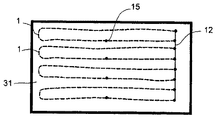
図1及び図2は、本発明による消火システムで利用される消火手段の簡略図を示す。この消火手段は、壁部材及び該壁部材によって画定される空間Wを備える、消火媒体を搬送する細長い管又はホース部材から形成される。壁部材は、少なくとも2つの層2、3から形成され、これらの少なくとも一方は、温度上昇の結果として溶融、燃焼、又は他の形で弱化する温度上昇に敏感な材料でできているため、空間W内で加圧される消火媒体が壁部材を通ってその外側に出ることができる。
Detailed Description of the Invention
1 and 2 show a simplified diagram of fire extinguishing means utilized in a fire extinguishing system according to the present invention. This fire extinguishing means is formed from an elongate tube or hose member carrying a fire extinguishing medium comprising a wall member and a space W defined by the wall member. The wall member is formed of at least two
管又はホース部材の壁層2、3の少なくとも一方は、開口4を含む耐火材料でできている。通常、壁層2、3の少なくとも一方は、布、有利にはスチールクロス等のワイヤクロスでできている。
At least one of the
層2、3の少なくとも一方は、開口4、薄肉部、又は同等物を含む。通常、補強層には容易に開口ができる。図2Aの実施形態では、補強層は、繊条要素(スレッド)4、5間に開口4が開いた編状体(ブレーディング)でできている。図2Bの実施形態では、補強層は、開口4を含む被覆である。当然ながら、補強層は、他の何らかの態様で構成することもできる。火災の場合には、ホース手段の表面層又は他の感熱部分の火災領域付近が火の影響によって燃焼又は溶融し、消火媒体を開口4を通して火災領域又はその付近に噴霧することができる。開口のサイズは、消火媒体が圧力によってホース手段に搬送されると微細なスプレーとして1つ又は複数の開口から噴霧されるように形成されることが有利である。
At least one of the
図示した実施形態では、外側の壁の第1の層3は感温材料でできており、少なくともこれに続くその下の層2は耐火性のより高い補強材料でできている。
In the illustrated embodiment, the
壁を外側から内側に考察すると、補強層2の下には感温性のより高い材料がある。これによって、ホース部材の内面が滑らかになり、流れ抵抗が小さくなる。
Considering the wall from the outside to the inside, under the reinforcing
消火手段で利用される消火媒体は通常、液体、ガス、又は液体とガスとの混合物である。 The fire extinguishing medium utilized in the fire extinguishing means is usually a liquid, a gas, or a mixture of liquid and gas.
本発明の有利な一実施形態によれば、それ自体が既知の耐高圧油圧ホースが管又はホース手段として利用されることが有利である。驚くべきことに、これは、本発明による消火手段で必要とされる適した特徴を有することが判明した。 According to an advantageous embodiment of the invention, it is advantageous that a high pressure resistant hydraulic hose known per se is used as the pipe or hose means. Surprisingly, it has been found that this has the appropriate characteristics required by the fire extinguishing means according to the invention.
図5の実施形態では、消火手段22が、管、ホース、及び/又はケーブル手段20に組み込まれている。これは、複数のケーブル又は管路21A、21B、21C、21D、21Eを備え得る。この場合、消火ラインの個別設置を行わなくてもよくなる。これは、特に、例えば数十キロメートルの長さであり得る長いケーブルを保護しようとする場合に大きな意義がある。管、ホース、又はケーブル手段は、種々の電気ケーブル又は電気通信ケーブル、媒体を移送する管路、又は火災の場合に消火手段が接続される保護対象となる同等物を含み得る。図5の実施形態は、管、ホース、又はケーブル手段の一部として消火媒体ライン22を接続する1つの方法にすぎない。消火媒体ライン22は、図1及び図2の実施形態で示されるものと同等の補強層を有する。
In the embodiment of FIG. 5, the fire extinguishing means 22 is incorporated into the tube, hose and / or cable means 20. This may comprise a plurality of cables or
本発明は、消火媒体源に接続される少なくとも1つの管又はホース手段1が保護対象物に配置される、消火方法にも関する。火災の影響によって、少なくとも1つの開口4がホース手段の壁に形成され、この壁は、少なくとも2つの層2、3から形成され、上記開口から消火媒体が管又はホース手段1によって火災領域及び/又はその付近にもたらされる。
The invention also relates to a fire extinguishing method in which at least one tube or hose means 1 connected to a fire extinguishing medium source is arranged on the object to be protected. Due to the influence of a fire, at least one opening 4 is formed in the wall of the hose means, which wall is formed from at least two
管又はホース手段1の壁2、3が有利には火災の熱による影響を受けることで、少なくとも1つの開口4が管又はホース手段の壁に形成され、この開口から消火媒体が噴き出すことができる。火災によって生じる熱影響は通常、少なくとも火災領域の付近にある部分を燃焼及び/又は溶融させるため、開口が形成されて、この開口から消火媒体が火災領域又はその付近に噴き出すことができる。
The
本方法の一実施形態によれば、少なくとも1つの層2が、長手方向及び横方向に複数の開口4を有する補強材料を含み、少なくとも1つの他の層3が、熱の影響によって燃焼及び/又は軟化及び溶融する耐消火媒体性材料を含み、壁部材の層2、3の少なくとも一方が影響を受けることで、少なくとも1つの開口4が壁部材に形成され、また圧力作用が消火媒体に与えられる結果として、消火媒体がホース手段の壁部材に形成された開口4から送り出される。
According to an embodiment of the method, at least one
本方法の一実施形態によれば、管又はホース手段1の消火媒体は待機(スタンバイ)圧力に維持され、消火媒体の流れはホース手段と消火媒体源との間で監視され、流れが設定値に達すると、より多くの消火媒体が消火配管系に搬送されることとなる。 According to one embodiment of the method, the extinguishing medium of the pipe or hose means 1 is maintained at a standby pressure, the flow of the extinguishing medium is monitored between the hose means and the extinguishing medium source and the flow is set to a set value. When this value is reached, more fire extinguishing medium will be transported to the fire extinguishing piping system.
さらに、消火媒体、有利には消火媒体ミストは、少なくとも1つの噴霧ヘッド15で噴霧され得る。
Furthermore, a fire extinguishing medium, preferably a fire extinguishing medium mist, can be sprayed with at least one spraying
消火媒体を供給する際には、有利には1,500,000〜30,000,000Pa(15〜300バール)の高圧を利用することができる。 When supplying the fire-extinguishing medium, it is advantageous to use a high pressure of 1,500,000 to 30,000,000 Pa (15 to 300 bar).
本発明の一実施形態による方法では、管又はホース部材が、消火媒体源16及び少なくとも1つの主管路12を有する消火システムの一部として利用され、主管路12に直接、又は分岐管13、14を介して少なくとも1つのホース手段1、1A、1B、1C、1D、1E、1Fが接続されるため、火災状況において、少なくとも1つの開口がホース部材に形成され、この開口から消火媒体が火災領域及び/又はその付近に噴霧され、必要であれば、消火媒体は、主管路12及び/又は分岐管13、14及び/又は管又はホース部材1、1A、1B、1C、1D、1E、1Fに配置される少なくとも1つの噴霧ヘッド15によって噴霧される。
In a method according to an embodiment of the present invention, a pipe or hose member is utilized as part of a fire extinguishing system having a fire extinguishing
本発明の一実施形態によれば、噴霧ヘッド15によって保護される空間とは異なる空間に管又はホース手段1、1A、1B、1C、1D、1E、1Fを向けることによって、その空間が当該管又はホース手段によって保護される。このような空間は、例えば、天井空間、屋根裏空間、又は噴霧ヘッドを用いることが不可能な他の空間であり得る。
According to one embodiment of the present invention, by directing the tube or hose means 1, 1A, 1B, 1C, 1D, 1E, 1F to a space different from the space protected by the
通常、管又はホース手段1、1A、1B、1C、1D、1E、1Fは、特にケーブルラック11を用いて、ケーブル、管、又は同等物等の火がつきやすい物体の付近に向けられる。
Typically, the tube or hose means 1, 1A, 1B, 1C, 1D, 1E, 1F are directed near a fireable object such as a cable, tube, or the like, particularly using the
さらに、管又はホース手段は、単独で、又は他の消火手段とともに、他の物体を保護するのに利用することもできる。このような他の保護対象物に適用できるものは、例えば、油又は化学物質タンク及びそれらの構造物、例えば、カバー構造体又はタンクの充填度に従って移動する同等物である。 Further, the tube or hose means can be used to protect other objects alone or in conjunction with other fire extinguishing means. Applicable to such other objects to be protected are, for example, oil or chemical tanks and their structures, such as cover structures or equivalents that move according to the filling level of the tank.
ホース手段22は、ケーブル20、管路、又はそれらの組み合わせに組み込まれて利用される(図5)。
The hose means 22 is used by being incorporated in the
液体、ガス、又は液体とガスとの混合物が、消火媒体として利用される。通常、水をそのまま消火媒体として、又は各要件及び用途に応じて異なる添加剤を加えるようにして利用することができる。したがってこの場合、特に消火媒体として、水性膜泡又は消火泡を利用することができる。さらに、特に状況に応じて、耐霜性を高める添加剤を利用してもよい。必要であれば、消火媒体としてガスを利用することもできる。ガスとして、窒素又は二酸化炭素等のそれ自体が既知の消火ガスを利用することができる。二酸化炭素等のガスは、ホース手段内で液体形態で加圧された状態で存在していてもよい。 Liquid, gas, or a mixture of liquid and gas is used as the fire extinguishing medium. Usually, water can be used as it is as a fire extinguishing medium or by adding different additives depending on each requirement and application. Therefore, in this case, an aqueous film foam or a fire-extinguishing foam can be used particularly as a fire-extinguishing medium. Furthermore, an additive that enhances frost resistance may be used depending on the situation. If necessary, gas can be used as a fire extinguishing medium. As the gas, a fire extinguishing gas known per se such as nitrogen or carbon dioxide can be used. A gas such as carbon dioxide may be present in a pressurized state in liquid form within the hose means.
一実施形態では、消火媒体はホース手段内を循環し、ホース手段1は冷却回路又はその一部として機能する。これは、例えば、加熱が問題となる大型ケーブルに関して非常に有利な実施形態である。 In one embodiment, the fire extinguishing medium circulates in the hose means, and the hose means 1 functions as a cooling circuit or part thereof. This is a very advantageous embodiment, for example for large cables where heating is a problem.
図3及び図4は、特にケーブルトンネル10に関して、本発明による装置の一実施形態を示す。ホース手段1A、1B、1C、1D、1E、1Fは、当然ながら、適当な消火媒体源に接続されている場合にのみにもケーブルトンネル10を保護するように利用することができる。図4は、消火媒体源16を概略的に示す。ポンプ装置17は、消火媒体源16及びホース手段1A...1Fに直接、又は図に示すように主ライン12及び分岐ライン13、14を介して接続される。ポンプ装置の代わりに、又はポンプ装置に加えて、少なくとも火災状況において圧力を用いて消火媒体をホース部材に搬送する圧力タンク等、別の適当な圧力源を利用してもよい。
3 and 4 show an embodiment of the device according to the invention, in particular with respect to the
したがって、本発明による消火装置の実施形態は、消火媒体源、及び消火媒体を少なくとも1つのノズル15に搬送する手段を備える。さらに、本装置は、消火媒体源に接続される少なくとも1つのホース手段1、1A、1B、1C、1D、1E、1Fを備え、当該ホース手段の壁部材2、3は、高熱の影響によって燃焼及び/又は軟化及び溶融する材料から少なくとも部分的に形成されるため、少なくとも管又はホース手段が火災領域の付近にある場合に消火媒体を噴霧する少なくとも1つの開口4が、管又はホース手段の壁に形成される。
Accordingly, an embodiment of the fire extinguishing apparatus according to the present invention comprises a fire extinguishing medium source and means for conveying the extinguishing medium to at least one
図3及び図4の装置は、主ライン12及びそれに接続される分岐ライン13、14を備え、ホース手段は分岐ライン13、14に接続される。種々のホース手段が分岐ライン間に配置されて、それ自体が既知の接続手段によってそれらに接続され、消火媒体は分岐ラインとホース手段との間でやり取りされる。
The apparatus of FIGS. 3 and 4 comprises a
本装置は、トンネル10等の細長い空間、特にケーブルトンネルに配置され、ホース手段1A、1B、1C、1D、1E、1Fは、トンネル内を通るライン、管、又は他の同等の保護対象物の付近に配置される。
The device is arranged in an elongated space, such as a
本装置のホース部材1A、1B、1C、1D、1E、1Fは、ケーブルラック11、天井空間、低床空間、又は同等の比較的狭い密閉空間に配置される。
The
本装置は、消火媒体の流れを監視する手段18を備える。通常は火災状況において、ホース部材1に孔が形成されると、消火媒体が孔から噴き出し始めて流れ検出器18から信号が送信され、この信号に基づいて配管系に搬送される消火媒体の量が増大される。したがって、これは、ポンプ手段17の始動又は圧力源と配管系との間の弁部材(図示せず)の開放の結果であり得る。
The apparatus comprises means 18 for monitoring the flow of the fire extinguishing medium. Normally, when a hole is formed in the
本装置は、スプリンクラ手段15等の噴霧手段も備える。図3及び図4では、空間10の上側部分に、有利には主ライン12に、噴霧ヘッド15、特に、火災の影響によって噴霧ヘッドの作動を行うアンプル又は他のトリガ手段が設けられたスプリンクラヘッドが配置される。したがって、火災の場合、流れ検出器によって得られる信号に基づいて管又はホース部材に開口が形成されるため、システムが作動され得る。噴霧ヘッド15は、火災の結果として噴霧ヘッドのアンプルが破壊されていなくても、必要であれば消火媒体を噴霧できるようなタイプのものであってもよい。
The apparatus also includes spraying means such as sprinkler means 15. 3 and 4, the sprinkler head is provided in the upper part of the
本発明による手段及び装置の別の有利な応用目的は、例えば屋根裏火災からの建物の保護である。図6及び図7は、本装置の概略実施形態を示す。通常、建物の屋根は、天井31と屋根32との間に低い空間を有し、この空間内には小屋組等の屋根の支持構造体(図示せず)がある。従来から、このような空間を従来の噴霧ヘッドで保護することは困難であり費用がかかっていた。この実施形態は、本発明による管又はホース手段1が、内部空間を保護するとともに噴霧ヘッド15につながる消火媒体流路の一部として利用されるという概念に基づく。この場合、本発明による管又はホース手段は、該当する空間を循環するように配置される。他方、管又はホース手段のみが保護対象物に、例えばその空間の床及び/又は天井に一定の間隔で配置されてもよい。この実施形態の有利な構成によれば、噴霧ヘッドにつながり建物の内部空間の保護に利用される消火媒体ラインは、本発明によれば、天井と屋根との間の空間に向けられているホース手段から成る。この場合、屋根裏空間は別個の噴霧ヘッドなしで保護されるようになることが有利である。したがって、天井空間又は同等物を保護することができる。
Another advantageous application purpose of the means and devices according to the invention is, for example, the protection of buildings from attic fires. 6 and 7 show a schematic embodiment of the device. Usually, the roof of a building has a low space between the
消火媒体として、水及び/又は消火を強化する添加剤を含んだ水等の水性消火媒体、及び/又は水性消火媒体とガスとの混合物、又はガスが利用される。 As the fire extinguishing medium, water and / or an aqueous fire extinguishing medium such as water containing an additive that enhances fire extinguishing, and / or a mixture of an aqueous fire extinguishing medium and a gas, or a gas is used.
本発明は上述の実施形態に限定されず、添付の特許請求の範囲内で変更可能であることが、当業者には自明である。本明細書において、組み合わせて示された複数の特徴は、独立した特徴とすることもできる。 It will be apparent to those skilled in the art that the present invention is not limited to the above-described embodiments and can be modified within the scope of the appended claims. In this specification, a plurality of features shown in combination may be independent features.
Claims (29)
Applications Claiming Priority (2)
| Application Number | Priority Date | Filing Date | Title |
|---|---|---|---|
| FI20040484A FI116886B (en) | 2004-04-02 | 2004-04-02 | Methods and equipment for fire fighting and equipment |
| PCT/FI2005/000171 WO2005094945A1 (en) | 2004-04-02 | 2005-04-01 | Fire-extinguishing method, apparatus and means |
Publications (1)
| Publication Number | Publication Date |
|---|---|
| JP2007530196A true JP2007530196A (en) | 2007-11-01 |
Family
ID=32104141
Family Applications (1)
| Application Number | Title | Priority Date | Filing Date |
|---|---|---|---|
| JP2007505569A Withdrawn JP2007530196A (en) | 2004-04-02 | 2005-04-01 | Fire extinguishing method, fire extinguishing device, and fire extinguishing means |
Country Status (9)
| Country | Link |
|---|---|
| US (1) | US20070205006A1 (en) |
| EP (1) | EP1729857A4 (en) |
| JP (1) | JP2007530196A (en) |
| AU (1) | AU2005227644A1 (en) |
| CA (1) | CA2559751A1 (en) |
| FI (1) | FI116886B (en) |
| MY (1) | MY140140A (en) |
| TW (1) | TW200600146A (en) |
| WO (1) | WO2005094945A1 (en) |
Cited By (1)
| Publication number | Priority date | Publication date | Assignee | Title |
|---|---|---|---|---|
| JP2009001984A (en) * | 2007-06-19 | 2009-01-08 | Inax Corp | Electric equipment |
Families Citing this family (5)
| Publication number | Priority date | Publication date | Assignee | Title |
|---|---|---|---|---|
| CN102657922B (en) * | 2012-05-23 | 2014-11-12 | 首钢京唐钢铁联合有限责任公司 | Nitrogen automatic fire fighting system for sealed cable tunnel |
| US20140202720A1 (en) * | 2013-01-22 | 2014-07-24 | GelTech Solutions, Inc. | Method and Device for Suppressing Electrical Fires in Underground Conduit |
| WO2014184791A1 (en) * | 2013-05-13 | 2014-11-20 | Israel Aerospace Industries Ltd. | A robotic supply system |
| MX2017002424A (en) * | 2014-08-28 | 2017-07-07 | Firetrace Usa Llc | Methods and apparatus for fire suppressant panel. |
| EP3259766B1 (en) * | 2015-02-20 | 2021-10-20 | Royston, Clifton | Ignition suppression circuiting technology |
Family Cites Families (14)
| Publication number | Priority date | Publication date | Assignee | Title |
|---|---|---|---|---|
| US2382120A (en) * | 1942-11-25 | 1945-08-14 | Okonite Callender Cable Co Inc | Electric cable system |
| US2585039A (en) * | 1949-02-11 | 1952-02-12 | George G Evans | Local automatic fire extinguishing system |
| US3138936A (en) * | 1962-08-31 | 1964-06-30 | Carrier Corp | Fusible protector for a refrigeration system |
| US3682250A (en) * | 1971-02-11 | 1972-08-08 | Lewis Eng Co | Enclosed and confined area automatic fire extinguisher hose and apparatus |
| US3858618A (en) * | 1973-01-10 | 1975-01-07 | Factory Mutual Res Corp | Piping for fire protection systems |
| FR2297643A1 (en) * | 1975-01-15 | 1976-08-13 | Zachariasen Nicolai | Fire fighting sprinkler system - has fire fighting material fed to plastic tubes in apertured metal tubes |
| GB2128084A (en) * | 1982-10-02 | 1984-04-26 | Alec Moses Messulam | Fire extinguisher |
| GB8926849D0 (en) * | 1989-11-28 | 1990-01-17 | Melton David L | Fire extinguisher |
| JPH0647106A (en) * | 1992-07-29 | 1994-02-22 | Yuichi Murayama | Fire-extinguishing water distributing pipe |
| AU713007B2 (en) * | 1996-05-22 | 1999-11-18 | Siemens Aktiengesellschaft | Means for fighting fire in at least one cable or line run |
| JPH10151218A (en) * | 1996-11-13 | 1998-06-09 | Rii Chen-Kun | Method for fire extinguishing |
| SE510679C2 (en) * | 1997-08-29 | 1999-06-14 | Trelleborg Viking Asa | Pipe or hose that can withstand high heat flux density and use of the pipe or hose |
| GB2349084B (en) * | 1999-03-27 | 2002-09-18 | David Laurence Melton | A temperature detector |
| US6161624A (en) * | 1999-11-29 | 2000-12-19 | The United States Of America As Represented By The Secretary Of The Air Force | Linear fire extinguisher |
-
2004
- 2004-04-02 FI FI20040484A patent/FI116886B/en active IP Right Grant
-
2005
- 2005-03-29 TW TW094109823A patent/TW200600146A/en unknown
- 2005-04-01 EP EP05717289A patent/EP1729857A4/en not_active Withdrawn
- 2005-04-01 JP JP2007505569A patent/JP2007530196A/en not_active Withdrawn
- 2005-04-01 CA CA002559751A patent/CA2559751A1/en not_active Abandoned
- 2005-04-01 MY MYPI20051480A patent/MY140140A/en unknown
- 2005-04-01 AU AU2005227644A patent/AU2005227644A1/en not_active Abandoned
- 2005-04-01 US US10/592,653 patent/US20070205006A1/en not_active Abandoned
- 2005-04-01 WO PCT/FI2005/000171 patent/WO2005094945A1/en not_active Application Discontinuation
Cited By (1)
| Publication number | Priority date | Publication date | Assignee | Title |
|---|---|---|---|---|
| JP2009001984A (en) * | 2007-06-19 | 2009-01-08 | Inax Corp | Electric equipment |
Also Published As
| Publication number | Publication date |
|---|---|
| FI116886B (en) | 2006-03-31 |
| CA2559751A1 (en) | 2005-10-13 |
| AU2005227644A1 (en) | 2005-10-13 |
| MY140140A (en) | 2009-11-30 |
| US20070205006A1 (en) | 2007-09-06 |
| EP1729857A1 (en) | 2006-12-13 |
| TW200600146A (en) | 2006-01-01 |
| WO2005094945A1 (en) | 2005-10-13 |
| EP1729857A4 (en) | 2009-04-08 |
| FI20040484A0 (en) | 2004-04-02 |
| FI20040484A (en) | 2005-10-03 |
Similar Documents
| Publication | Publication Date | Title |
|---|---|---|
| JP2007530196A (en) | Fire extinguishing method, fire extinguishing device, and fire extinguishing means | |
| RU2317834C2 (en) | Fire-extinguishing method and device | |
| JP4554617B2 (en) | Equipment for preventing and extinguishing fire | |
| JP2002035147A (en) | Refuge facility for tunnel | |
| SE509895C2 (en) | Method and equipment in emergency services | |
| JP3626207B2 (en) | Fire extinguisher | |
| AU778513B2 (en) | Fire-fighting system for car tunnels | |
| JP2023096172A (en) | Sheet developing device in disaster prevention facility | |
| JP4776410B2 (en) | Fire extinguishing system | |
| JP2005536320A (en) | Fire extinguishing devices and fire guidance systems designed especially for tunnels and similar structures | |
| US20230009507A1 (en) | A system and method for controlling fire in a building | |
| JP2648829B2 (en) | Fire extinguishing method for cable in canal and foam fire extinguisher | |
| CN201088798Y (en) | Pressure-storage suspension type multiple-layer solid injection extinguishing device | |
| JP2001157721A (en) | Fire extinguishing equipment | |
| KR100622693B1 (en) | Water spray nozzle for water based fire compartment wall | |
| JP2007006932A (en) | Fire-extinguishing equipment | |
| JP2007319513A (en) | Fire-fighting equipment consisting of alternately disposed closed type sprinkler head | |
| JPH10118214A (en) | Device and method for fire extinguishing and smoke elimination using water-mist | |
| JP3286370B2 (en) | Exhaust duct fire extinguishing system for drying oven | |
| JP2009505759A (en) | Stationary fire extinguishing system with cleaning equipment | |
| JP4827572B2 (en) | High expansion foam fire extinguishing equipment | |
| RU2685866C1 (en) | Method of fire protection and system for its implementation | |
| KR200321478Y1 (en) | Water spray nozzle for water based fire compartment wall | |
| RU2205674C2 (en) | Fire suppressing apparatus | |
| JP2004160161A (en) | Fire-fighting facility |
Legal Events
| Date | Code | Title | Description |
|---|---|---|---|
| A621 | Written request for application examination |
Free format text: JAPANESE INTERMEDIATE CODE: A621 Effective date: 20080313 |
|
| A761 | Written withdrawal of application |
Free format text: JAPANESE INTERMEDIATE CODE: A761 Effective date: 20090925 |
|
| A521 | Written amendment |
Free format text: JAPANESE INTERMEDIATE CODE: A821 Effective date: 20090925 |