JP2007529978A - Method for manufacturing a winding support for an electric machine - Google Patents
Method for manufacturing a winding support for an electric machine Download PDFInfo
- Publication number
- JP2007529978A JP2007529978A JP2007503317A JP2007503317A JP2007529978A JP 2007529978 A JP2007529978 A JP 2007529978A JP 2007503317 A JP2007503317 A JP 2007503317A JP 2007503317 A JP2007503317 A JP 2007503317A JP 2007529978 A JP2007529978 A JP 2007529978A
- Authority
- JP
- Japan
- Prior art keywords
- pole teeth
- winding
- slot
- magnetic pole
- tooth
- Prior art date
- Legal status (The legal status is an assumption and is not a legal conclusion. Google has not performed a legal analysis and makes no representation as to the accuracy of the status listed.)
- Withdrawn
Links
Images


Classifications
-
- H—ELECTRICITY
- H02—GENERATION; CONVERSION OR DISTRIBUTION OF ELECTRIC POWER
- H02K—DYNAMO-ELECTRIC MACHINES
- H02K15/00—Methods or apparatus specially adapted for manufacturing, assembling, maintaining or repairing of dynamo-electric machines
- H02K15/08—Forming windings by laying conductors into or around core parts
- H02K15/095—Forming windings by laying conductors into or around core parts by laying conductors around salient poles
-
- H—ELECTRICITY
- H02—GENERATION; CONVERSION OR DISTRIBUTION OF ELECTRIC POWER
- H02K—DYNAMO-ELECTRIC MACHINES
- H02K15/00—Methods or apparatus specially adapted for manufacturing, assembling, maintaining or repairing of dynamo-electric machines
- H02K15/08—Forming windings by laying conductors into or around core parts
- H02K15/09—Forming windings by laying conductors into or around core parts by laying conductors into slotted rotors
-
- H—ELECTRICITY
- H02—GENERATION; CONVERSION OR DISTRIBUTION OF ELECTRIC POWER
- H02K—DYNAMO-ELECTRIC MACHINES
- H02K1/00—Details of the magnetic circuit
- H02K1/06—Details of the magnetic circuit characterised by the shape, form or construction
- H02K1/22—Rotating parts of the magnetic circuit
- H02K1/24—Rotor cores with salient poles ; Variable reluctance rotors
-
- H—ELECTRICITY
- H02—GENERATION; CONVERSION OR DISTRIBUTION OF ELECTRIC POWER
- H02K—DYNAMO-ELECTRIC MACHINES
- H02K1/00—Details of the magnetic circuit
- H02K1/06—Details of the magnetic circuit characterised by the shape, form or construction
- H02K1/22—Rotating parts of the magnetic circuit
- H02K1/26—Rotor cores with slots for windings
-
- H—ELECTRICITY
- H02—GENERATION; CONVERSION OR DISTRIBUTION OF ELECTRIC POWER
- H02K—DYNAMO-ELECTRIC MACHINES
- H02K3/00—Details of windings
- H02K3/46—Fastening of windings on the stator or rotor structure
- H02K3/48—Fastening of windings on the stator or rotor structure in slots
- H02K3/487—Slot-closing devices
- H02K3/493—Slot-closing devices magnetic
-
- H—ELECTRICITY
- H02—GENERATION; CONVERSION OR DISTRIBUTION OF ELECTRIC POWER
- H02K—DYNAMO-ELECTRIC MACHINES
- H02K3/00—Details of windings
- H02K3/46—Fastening of windings on the stator or rotor structure
- H02K3/52—Fastening salient pole windings or connections thereto
- H02K3/527—Fastening salient pole windings or connections thereto applicable to rotors only
-
- Y—GENERAL TAGGING OF NEW TECHNOLOGICAL DEVELOPMENTS; GENERAL TAGGING OF CROSS-SECTIONAL TECHNOLOGIES SPANNING OVER SEVERAL SECTIONS OF THE IPC; TECHNICAL SUBJECTS COVERED BY FORMER USPC CROSS-REFERENCE ART COLLECTIONS [XRACs] AND DIGESTS
- Y10—TECHNICAL SUBJECTS COVERED BY FORMER USPC
- Y10T—TECHNICAL SUBJECTS COVERED BY FORMER US CLASSIFICATION
- Y10T29/00—Metal working
- Y10T29/49—Method of mechanical manufacture
- Y10T29/49002—Electrical device making
- Y10T29/49009—Dynamoelectric machine
-
- Y—GENERAL TAGGING OF NEW TECHNOLOGICAL DEVELOPMENTS; GENERAL TAGGING OF CROSS-SECTIONAL TECHNOLOGIES SPANNING OVER SEVERAL SECTIONS OF THE IPC; TECHNICAL SUBJECTS COVERED BY FORMER USPC CROSS-REFERENCE ART COLLECTIONS [XRACs] AND DIGESTS
- Y10—TECHNICAL SUBJECTS COVERED BY FORMER USPC
- Y10T—TECHNICAL SUBJECTS COVERED BY FORMER US CLASSIFICATION
- Y10T29/00—Metal working
- Y10T29/49—Method of mechanical manufacture
- Y10T29/49002—Electrical device making
- Y10T29/4902—Electromagnet, transformer or inductor
- Y10T29/49073—Electromagnet, transformer or inductor by assembling coil and core
Abstract
電気機械(10)のための、複数の磁極歯(20)を有する巻線支持体(14)を製造するための方法が提案される。隣り合う磁極歯(201,208)は、その間に少なくとも1つのスロット(211)を制限していて、このスロット(211)内にそれぞれ少なくとも1つの巻線(18)が装着される。これらの磁極歯(201,208)は装着前に互いに電気機械(10)内に組み込むための組込み位置を占めている。1つのスロット(211)を制限するこれらの磁極歯(201,208)のうちの少なくとも1つの磁極歯は、少なくとも1つのスロット(211)を巻線(18)で装着する前に力作用(36)によって装着位置に曲げられ、その結果、磁極歯(20)が制限している少なくとも1つのスロット(211)の横断面は拡大される。次いで、巻線(181)がスロット(211)内に挿入される。これに続いて、隣り合う磁極歯(201,208)の少なくとも1つの磁極歯が、装着位置から組込み位置に移される。これによって、高い銅占積率ひいては機械(10)の高い出力を得ることができる。 A method for manufacturing a winding support (14) having a plurality of pole teeth (20) for an electric machine (10) is proposed. Adjacent magnetic pole teeth (201, 208) limit at least one slot (211) therebetween, and at least one winding (18) is mounted in each slot (211). These magnetic pole teeth (201, 208) occupy an assembling position for assembling each other into the electric machine (10) before mounting. At least one of these pole teeth (201, 208) that restricts one slot (211) is force applied (36) before mounting at least one slot (211) with winding (18). ), So that the cross section of the at least one slot (211) restricted by the pole teeth (20) is enlarged. The winding (181) is then inserted into the slot (211). Following this, at least one pole tooth of the adjacent pole teeth (201, 208) is moved from the mounting position to the assembly position. This makes it possible to obtain a high copper space factor and thus a high output of the machine (10).
Description
背景技術
本発明は、請求項1の上位概念部に記載の、電気機械のための巻線支持体を製造するための方法から出発する。このような形式の巻線支持体は複数の磁極歯を有している。隣り合う磁極歯はその間に少なくとも1つのスロットを有していて、このスロット内に少なくとも1つの巻線がそれぞれ挿入される。これらの磁極歯は、巻線をスロット内に挿入する前に既に、電気機械に組み込むための後の組込み位置を互いに占めている。巻線はこの組込み位置において挿入される。これによって、巻線支持体もしくは電気機械は、最大でどの程度の銅占積率を有することができるかも既に規定されている。銅占積率はモータ出力の指数でもある。
The invention starts from a method for manufacturing a winding support for an electric machine according to the superordinate concept of claim 1. This type of winding support has a plurality of magnetic pole teeth. Adjacent pole teeth have at least one slot between them, and at least one winding is inserted into each slot. These magnetic pole teeth already occupy each other in a later installation position for installation in an electric machine before inserting the winding into the slot. The winding is inserted in this assembled position. This already defines how much copper space factor or electrical machine can have a maximum copper space factor. Copper space factor is also an index of motor output.
発明の利点
請求項1の特徴部に記載した構成を有する、電気機械のための巻線支持体を製造するための本発明による方法が有する利点は、比較可能な構造サイズの巻線支持体に比べて、高い銅占積率によって高い出力を得ることができるということである。このために、電気機械のための、複数の磁極歯を有する巻線支持体を製造するための方法では、隣り合う磁極歯が、その間に少なくとも1つのスロットを制限していて、このスロットにはそれぞれ少なくとも1つの巻線が装着(挿入)され、この場合、複数の磁極歯は電気機械内に組み込むための組込み位置をそれぞれ有していて、1つのスロットを制限するこれらの磁極歯のうちの少なくとも1つの磁極歯は、巻線の装着前に力作用によって装着位置に曲げられ、その結果、磁極歯が制限している少なくとも1つのスロットの横断面は拡大され、次いで、スロットは巻線を装着され、その後、隣り合う磁極歯の少なくとも1つが、装着位置から組込み位置に移される。
Advantages of the invention The advantages of the method according to the invention for producing a winding support for an electric machine with the configuration as defined in the features of claim 1 are in a winding support of comparable structure size. In comparison, a high output can be obtained with a high copper space factor. To this end, in a method for manufacturing a winding support having a plurality of pole teeth for an electrical machine, adjacent pole teeth limit at least one slot therebetween, At least one winding is mounted (inserted) each, and in this case, the plurality of pole teeth each have an assembly position for incorporation into the electric machine, and the one of these pole teeth that limit one slot At least one pole tooth is bent into the mounting position by force action before mounting of the winding, so that the cross-section of at least one slot restricted by the pole teeth is enlarged, and the slot then turns the winding After mounting, at least one of the adjacent magnetic pole teeth is moved from the mounting position to the installation position.
有利には、力作用は直接に磁極歯に作用する。これによって、作業の精確な干渉が可能になる。 Advantageously, the force action acts directly on the pole teeth. This allows precise interference of work.
全ての磁極歯は順次に装着位置に曲げられ、巻線がそれぞれ挿入された後に、組込み位置に移されると有利である。なぜならば、これによって全てのスロットは高い銅占積率を有するからである。 It is advantageous if all the pole teeth are bent sequentially into the mounting position and moved to the assembly position after each winding has been inserted. This is because all slots have a high copper space factor.
本発明の有利な構成では、曲げられる少なくとも1つの磁極歯が、弾性的な領域において曲げられ、巻線の挿入後に力作用が取り除かれることで、弾性的な領域の固有弾性によって組込み位置に戻る。これによって、方法は比較的に簡単に実施可能である。なぜならば、磁極歯の寸法規定通りの調整のための手間が必要にならないからである。 In an advantageous configuration of the invention, the at least one pole tooth to be bent is bent in the elastic region and the force action is removed after the winding is inserted, so that it returns to the built-in position by the inherent elasticity of the elastic region. . This makes the method relatively easy to implement. This is because no labor is required for adjustment according to the stipulated size of the magnetic pole teeth.
本発明の別の有利な構成では、曲げ開かれる少なくとも1つの磁極歯が、塑性的な領域において曲げられ、巻線の挿入後に力作用を反転させることで、塑性変形によって組込み位置に戻される。これによって、さらに高い銅占積率を得ることができる。 In another advantageous configuration of the invention, the at least one pole tooth to be bent open is bent in the plastic region and returned to the integrated position by plastic deformation by reversing the force action after insertion of the winding. As a result, a higher copper space factor can be obtained.
互いに直接に隣り合う磁極歯の間の間隔が拡大されることで、これらの磁極歯が曲げ開かれると有利である。なぜならば、これによって対称的な力作用が可能になり、とりわけ、スロットの高い巻線挿入量が可能になる。 It is advantageous if the pole teeth are bent open by increasing the spacing between the pole teeth directly adjacent to each other. This allows a symmetrical force action, in particular a high slot insertion amount of the slot.
磁極歯の間の間隔が拡大されることにより、間に1つの別の磁極歯を配置している複数の磁極歯が曲げ開かれると、隣り合う2つのスロットに同時に巻線を備え付けることができるか、またはこれらのスロットの間に設けられている磁極歯に単一歯巻線を取り付けることができる。 When the gap between the magnetic pole teeth is expanded and a plurality of magnetic pole teeth with one other magnetic pole tooth arranged between them is bent open, it is possible to equip two adjacent slots with windings simultaneously. Alternatively, single tooth windings can be attached to the pole teeth provided between these slots.
巻線の最良の挿入は、それぞれペアになって、少なくとも挿入しようとする巻線を受容する2つのスロットの磁極歯を曲げ開き、次いで、この巻線が挿入され、これに続いて時計回りまたは反時計回りで、それぞれ直接的にまたは間接的に対を成して少なくとも1つの巻線を受容する次のスロットの磁極歯が曲げ開かれることで達成され、このことは巻線支持体に巻線が完全に備え付けられるまで繰り返される。 The best insertion of windings is each paired to bend open at least two slot pole teeth that receive the winding to be inserted, and then this winding is inserted, followed by clockwise or Counter-clockwise, this is achieved by bending open the pole teeth of the next slot, each directly or indirectly paired to receive at least one winding, which is wound on the winding support. Repeat until the line is fully installed.
磁極歯がそれぞれ1つの歯ネック部と1つの歯ヘッド部とを有していると、この方法は特に有利に使用可能である。この場合、歯ヘッド部は歯ネック部に対して直交する方向に突出する区分を有していて、この区分は巻線を受容するためのアンダカットされたスロットのアンダカットを制限し、かつスロットスリットを形成する。この場合、巻線を挿入するために、実質的に少なくともスロットスリットの幅が拡大される。アンダカットによって、巻線の特に多くの巻条を挿入することができる。 This method can be used particularly advantageously if the pole teeth each have one tooth neck and one tooth head. In this case, the tooth head has a section projecting in a direction perpendicular to the tooth neck, which section limits the undercut of the undercut slot for receiving the winding and the slot A slit is formed. In this case, in order to insert the winding, at least the width of the slot slit is substantially enlarged. By undercutting, particularly many windings of the winding can be inserted.
このような形式の方法によって製造された巻線支持体は、特に高い銅占積率を有している。 Winding supports produced by this type of method have a particularly high copper space factor.
このような形式の巻線支持体に、2つの磁極歯の間に設けられているスロット底部から磁極歯への移行部が少なくとも角張って(実質的に丸みを付けずに)形成されていると、磁極歯の低い抵抗係数が得られる。これによって、曲げるために必要な力は軽減される。磁極歯がそれぞれ1つの歯ネック部と1つの歯ヘッド部とを有している巻線支持体においては、歯ヘッド部が歯ネック部に対して直交する方向に突出している、アンダカットされたスロットのアンダカットを形成している区分を有しており、この場合、磁極歯からアンダカットへの移行部は角張って形成されていて、この効果はさらに強化される。さらに、この手段が有する利点は、スロット横断面の不変の拡大によって、巻線のために大きな容量が形成されることである。 In such a type of winding support, the transition from the slot bottom portion to the magnetic pole teeth provided between the two magnetic pole teeth is formed at least squarely (substantially without being rounded). A low resistance coefficient of the magnetic pole teeth can be obtained. This reduces the force required to bend. In the winding support in which the magnetic pole teeth each have one tooth neck part and one tooth head part, the tooth head part protrudes in a direction perpendicular to the tooth neck part, and is undercut It has a section forming an undercut of the slot, in which case the transition from the pole teeth to the undercut is formed angularly, further enhancing this effect. Furthermore, an advantage of this measure is that a large capacitance is formed for the winding due to the constant expansion of the slot cross section.
有利な構成では、このような形式の巻線支持体が、インナロータ型のアーマチュアまたはアウタロータ型のステータであって、この巻線支持体では磁極歯が半径方向外側に向けられている。なぜならば、磁極歯は簡単に曲げ開くことができるからである。 In an advantageous configuration, this type of winding support is an inner rotor type armature or outer rotor type stator, in which the pole teeth are directed radially outward. This is because the magnetic pole teeth can be easily bent open.
このような形式の巻線支持体を有する電気機械は、比較可能な構造サイズの電気機械と比べて、高い銅占積率の基づき、高い出力を有している。 An electric machine having a winding support of this type has a higher output based on a higher copper space factor than an electric machine of comparable structure size.
方法を実施するために、少なくとも1つの磁極歯を曲げるために少なくとも1つの器具を有している装置によって、この方法は簡単に実施され得る。 In order to carry out the method, this method can easily be carried out by a device having at least one instrument for bending at least one pole tooth.
装置が2つの隣り合う磁極歯を曲げるために少なくとも1つの器具を有していると、装置のさらなる改良が得られる。したがって、スロットは大きく曲げ開らかれ得る。 A further improvement of the device is obtained if the device has at least one instrument for bending two adjacent pole teeth. Therefore, the slot can be greatly bent open.
装置が、1つの巻線が挿入される2つのスロットの2つの磁極歯を曲げるために少なくとも1つの器具を有していると、この装置のさらに別の改良が得られる。これによって特に、ペアで1つの巻線を受容するスロットは簡単に曲げ開かれ得る。 A further improvement of the device is obtained if the device has at least one instrument for bending the two pole teeth of the two slots into which one winding is inserted. In particular, this makes it possible to simply bend and open slots that receive one winding in pairs.
別の利点および有利な構成が、請求項2以下および実施例の説明から明らかになる。 Further advantages and advantageous configurations will become apparent from the claims 2 and below and from the description of the examples.
図面
実施例が図示されていて、以下に詳しく説明されている。
Drawings Exemplary embodiments are illustrated and described in detail below.
図1は、電気機械の横断面図であり、
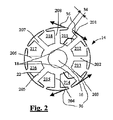
図2は、図1のアーマチュアを示す図であり、
図3は、象徴的に図示された巻線を備えた図1のアーマチュアを示す図であり、
図4は、方法を実施するための極めて簡略的に示した装置におけるアーマチュアを示す図である。
FIG. 1 is a cross-sectional view of an electric machine,
FIG. 2 is a diagram showing the armature of FIG.
FIG. 3 is a diagram showing the armature of FIG. 1 with the symbolically illustrated windings;
FIG. 4 shows an armature in a very simplified apparatus for carrying out the method.
実施例の説明
図1には、回転式の電気機械10が簡略的に横断面図で示されている。電気機械10は電動モータであってよく、この電動モータは自動車において、たとえばシートアジャスタ、ウィンドリフタおよびワイパ駆動装置等に使用される。しかし、この電気機械10は発電機であってもよい。
DESCRIPTION OF THE EMBODIMENTS In FIG. 1, a rotary
ケーシング12内にはアーマチュア14が配置されていて、このアーマチュア14はシャフト16に配置されている。したがって、シャフト16を有しているかまたは有していないアーマチュア14は、電気機械10のための巻線保持体である。アーマチュア14は、金属薄板またはいわゆるSMC(Soft Magnetic Composite)材料(軟磁性複合材料)から成る薄片積層体として形成されている。金属薄板から成る薄片積層体の場合、個別金属薄板(符号14に相当)の厚さは0,5mmであり、このことは1/10ミリメートル範囲内の差異を含んでいてよい。
An
アーマチュア14は複数の巻線18を有している。図面を見やすくするために、図1では1つの巻線18だけが概略的に示されている。アーマチュア14の円形の区分19から、複数の磁極歯20が半径方向外側に向かって突出していて、これらの磁極歯20は、巻線18を受容するためのスロット21を制限しもしくは形成している。本実施例では、個別に8個の磁極歯201,202,203,204,205,206,207,208が設けられている。これらの磁極歯20に対応するようにして、8個のスロット211,212,213,214,215,216,217,218がある。もちろん、別の個数も可能である。これらの磁極歯20はそれぞれ、区分19から出発している1つの歯ネック部22と、この歯ネック部22に接続している1つの歯ヘッド部24とを有している。歯ネック部22の間の、区分19の外周面にスロット21のスロット底部25がそれぞれ形成されている。
The
スロット底部25から歯ネック部22もしくは磁極歯20への移行部は、ほぼ角張って形成されている。つまり、移行部は通常のように丸みをつけられていない。理想的には、移行部は完全に角張っている。しかし、1mm以下の移行部曲率半径はまだ許容され、この場合、0,5mm以下の移行部曲率半径が有利である。移行部は確かに角張っていると有利である。しかし、アーマチュア14の個別金属薄板(同じく符号14)の厚さよりも小さい曲率半径は、撓みに際し良好な効果をもたらす。厚さは典型的には、たとえば約0,5mmであるが、10分の2,3ミリメートルの増減があってもよい。
The transition from the
スロット211は、スロット214とペアになって1つの共通の巻線18を受容する。同様のことをスロット212はスロット215と、スロット213はスロット216と、スロット214はスロット217と、スロット215はスロット218と、スロット216はスロット211と、スロット217はスロット212と、最後にスロット218はスロット213とそれぞれペアになって行う。このことは図3に詳細に示されている。
歯ネック部22はアーマチュア14の周面に、有利には均等に配分されていて、かつ真っ直ぐに突出している。つまり歯ネック部22は湾曲して延びているものではない。しかし、歯ネック部22が湾曲して延びる実施例も考えられる。さらに、歯ネック部22は、ほぼ均一の幅を有している。しかし択一的に、この幅は変化してもよく、つまり、内側から外側に向かって狭幅になってもよく、広幅になってもよい。
The
各歯ヘッド部24は、歯ネック部22に対して直交する方向に突出していて、かつ互いに逆の方向に向かう複数の区分28を有している。これらの区分28はアンダカット30を形成し、これによって、このアンダカット30が、アンダカットされたスロット21を制限している。さらに、区分28は、幅34を有するスロットスリット32を制限している。
Each
歯ネック部22からアンダカット30への移行部は、ほぼ角張って形成されていて、つまり、移行部は通常のように丸みを付けられていない。理想的には、移行部は完全に角張っている。しかし、1mm以下の移行部曲率半径は許容され、この場合、0,5mm以下の移行部曲率半径が有利である。移行部は確かに角張っていると有利である。しかし、アーマチュア14の個別金属薄板(同じく符号14)の厚さよりも小さい曲率半径は、撓みに際し良好な効果をもたらす。厚さは典型的には、たとえば約0,5mmであるが、しかし、10分の2,3ミリメートルの増減があってよい。
The transition from the
電動モータ10のためのアーマチュア14を製造するための方法は、図2に基づき詳細に説明される。
The method for manufacturing the
まず、金属薄板打抜き積層体の製造後には、アーマチュア14の磁極歯20は、まだ、図1にも示された組込み位置にある。この組込み位置で、アーマチュア14は電動モータ10内に嵌め込まれ得る。
First, after manufacture of the sheet metal stamped laminate, the
しかしながら、巻線18の装着の前に、直接に隣り合う磁極歯208と磁極歯201および磁極歯203と磁極歯204とが拡開される。これにより、磁極歯208と磁極歯201および磁極歯203と磁極歯204とによって制限されているスロット211およびスロット214は拡大される。スロット211およびスロット214の横断面の拡大は、たとえば、磁極歯20の周面に設けられた切欠きに係合する工具によって行われ、これによって矢印36で示された力作用が生ぜしめられる。このことは図4においてさらに詳細に説明される。この場合、磁極歯20が占める位置は、以下、装着位置と呼称される。今や巻線18は、巻成によってまたは予め形成されたエアコイルを挿入することによって設けられる。この場合、エアコイルの挿入は、スロット21がアンダカットされておらず、磁極歯20が歯ヘッド部24を有していない場合に有利である。この方法は図示の磁極歯20にも有利に用いられるものであって、これらの磁極歯20はそれぞれ、歯ネック部22に対して直交する方向に突出している、スロットスリット32を形成する区分28を備えた1つの歯ネック部22と1つの歯ヘッド部24とを有している。この場合、巻線18を挿入するために、少なくともスロットスリット32の幅は拡大される。
However, the
スロット21の横断面が拡大されているので、巻線18の多くの数の巻条を設けすることができる。巻線18が挿入された後に力作用は再び取り除かれる。これにより、磁極歯201と磁極歯208および磁極歯204と磁極歯205とは再び互いに接近する。巻線18の巻条の間にある間隙によって、銅線の絶縁層が破壊されることなく、巻線18をさらにわずかに圧縮することができる。
Since the cross section of the slot 21 is enlarged, a large number of windings of the winding 18 can be provided. After the winding 18 is inserted, the force action is removed again. As a result, the
第1のペアの磁極歯208と磁極歯201および磁極歯203と磁極歯204との後に、アーマチュア14は、360度をスロット21の数で割った角度だけ、つまり45度だけ回動させられ−時計回りでも反時計回りでもいいが、図2では反時計回り−、磁極歯201と磁極歯202および磁極歯204と磁極歯205とが装着位置に移される。これらの磁極歯20の間にあるスロット212およびスロット215には、巻線18が備え付けられ、スロット212およびスロット215は再び組込み位置に移される。磁極歯201と磁極歯202および磁極歯204と磁極歯205とに続いて、磁極歯202と磁極歯203および磁極歯205と磁極歯206とが拡開され、これらの磁極歯の間に設けられているスロット213およびスロット216には、巻線18が備え付けられ、同様に組込み位置に再び移される。続いて、さらに同じ作業が、磁極歯203と磁極歯204および磁極歯207と磁極歯208とに対して行われる。つまり、全ての磁極歯20は順次に装着位置へ曲げられ、かつそれぞれに巻線18が挿入された後に組込み位置に移される。このようにして巻線18の挿入はさらに4回、各スロット21の左右の面が巻成されるまで続けられる。したがって、最終的にアーマチュア14全体に巻線18が備え付けられる。装着の順序に関しては、ここではさらに図3に記載した実施例も参照されたい。
After the first pair of
1つの巻線18を受容するそれぞれ2つのスロット21間の磁極歯20が曲げ開かれ、次いで巻線18が挿入され、これに続き、時計回りまたは反時計回りの方向で、ペアを成して1つの巻線18を受容する次のスロット21間の磁極歯20が曲げ開かれ、このことはアーマチュア14に巻線18が完全に備え付けられるまで繰り返される。
The
磁極歯20は、力作用が取り除かれた後に再び組込み位置に戻る。この理由は、曲げられる磁極歯20はそれぞれ弾性のある領域において曲げられ、かつ巻線18の挿入後に力作用36が取り除かれることによって、磁極歯20の固有弾性に基づき組込み位置に戻る、もしくは磁極歯20の固有弾性により組込み位置に戻されるからである。
The
択一的に、曲げ開かれる磁極歯20は弾性的な領域ではなく塑性的な領域において曲げられ−または弾性的な領域と塑性変形的な領域とにおいて−、巻線18の挿入後に力作用36が反転することで、塑性変形により組込み位置に戻されるということも可能である。磁極歯20は弾性的な領域における曲げ開きよりも、塑性的な領域における曲げ開きによって大きく拡開されるので、スロット21の横断面もより大きくなり、これによって巻線18の多くの数の巻条を配置することができる。
Alternatively, the
直接に隣り合う磁極歯を互いに曲げ開くことの他に、少なくとも1つの別の磁極歯20を間に置いて位置している磁極歯20を互いに曲げ開くこともでき、これらの磁極歯間の間隔を拡大することも可能である。たとえば、磁極歯201および磁極歯203は曲げ開かれ、この場合、差し当たって磁極歯202は曲げられない。同時に、磁極歯205および磁極歯207を曲げることもでき、この場合、同様に磁極歯206は差し当たり曲げられない。この関係において、これらの磁極歯は間接的に隣り合っていると見なされる。この場合、1つの巻線18がスロット211およびスロット214内に挿入され、同時に別の1つの巻線18がスロット218およびスロット215内に挿入される。これに次いで、アーマチュア14は時計回りまたは反時計回りに、360度をスロット21の数で割った角度、つまり45度だけ回動送りされる。だだし、アーマチュア14は二重の巻成により、さらに3回だけ回動される。
In addition to bending the adjacent magnetic pole teeth directly to each other, the
重要なことは、1つのスロット21を制限している複数の磁極歯20の少なくとも1つの磁極歯20が、スロット21に巻線18を装着する前に力作用によって装着位置に曲げられることであり、磁極歯によって制限している少なくとも1つのスロット21の横断面は拡大され、次いで巻線18はスロット21内に挿入され、これに引き続き、隣り合う複数の磁極歯20の少なくとも1つの磁極歯20が、装着位置から組込み位置に移される。
What is important is that at least one
図3に基づき、既に先行技術から周知の、スロット21内の巻線18の完成した配置は改めて明らかになる。
Based on FIG. 3, the completed arrangement of the
磁極歯201と磁極歯203との周囲およびスロット211ならびにスロット214内に巻線181があり、
磁極歯202と磁極歯204との周囲およびスロット212ならびにスロット215内に巻線182があり、
磁極歯203と磁極歯205との周囲およびスロット213ならびにスロット216内に巻線183があり、
磁極歯204と磁極歯206との周囲およびスロット214ならびにスロット217内に巻線184があり、
磁極歯205と磁極歯207との周囲およびスロット215ならびにスロット218内に巻線185があり、
磁極歯206と磁極歯208との周囲およびスロット216ならびにスロット211内に巻線186があり、
磁極歯207と磁極歯201との周囲およびスロット217ならびにスロット212内に巻線187があり、
磁極歯208と磁極歯202との周囲およびスロット218ならびにスロット213内に巻線188がある。
There are
There are
There are windings 183 around the
There is a winding 184 around the
There are
There are
There are
There are
ここでは、巻線18は、181,182,183,184,185,186,187,188の順序で順次に装着される。この場合、1つのスロット21を制限する2つの磁極歯20は曲げ開かれる。この場合の利点は、スロット21を大きく曲げ開き、これによって、高い占積率を可能にできることにある。
Here, the
択一的に、巻線181と巻線185、巻線182と巻線186、巻線183と巻線187および巻線184と巻線188とは平行に巻くことができる。この場合、有利には、2つの巻線18を一緒に装着することができ、このことは工程時間を短縮する。
Alternatively, the winding 181 and winding 185, the winding 182 and winding 186, the winding 183 and winding 187, and the winding 184 and winding 188 can be wound in parallel. In this case, advantageously, the two
もちろん、記載の順序は例示しただけであり、遵守する必要はない。多くの変化実施例が知られている。 Of course, the order of description is merely exemplary and need not be observed. Many variations are known.
図4には、磁極歯201,208と磁極歯203,204とが、記載の方法を実施するための、象徴的にかつ部分断面図もしくは部分的に図示されただけの装置42の2つのトング38,40で、どのように曲げ開かれるかが示されている。装置42は、少なくとも1つの磁極歯20を曲げるために少なくとも1つの器具38,40を有していることが望まれる。なぜならば、たとえば、磁極歯201だけを曲げることも可能であるからである。しかし、有利には、装置42は、スロット211の2つの隣り合う磁極歯201と磁極歯208とを曲げるために、トング38またはトング40の一部分、たとえばフックの形をした、少なくとも1つの器具を有している。しかし、既に示したように、装置42は少なくとも1つの器具38,40を有していて、この器具38,40は、ペアで1つの巻線18が挿入される2つのスロット211およびスロット214の2つの磁極歯201と磁極歯208および磁極歯203と磁極歯204とを曲げるようになっていると有利である。トング38,40は磁極歯201と磁極歯207および磁極歯203と磁極歯205とを曲げ開くこともでき、この場合、磁極歯204と磁極歯208とは直立したままであり、その結果、スロット211とスロット214およびにスロット218とスロット215とにそれぞれ1つの巻線18が挿入され得る。もちろん、前記のように、別のスロット21は次いで順々に巻成される。アーマチュア14の固定は、たとえばシャフト16によって行われる。
In FIG. 4, the
本発明は、アーマチュア14の形をした巻線支持体に限定されるものではない。図面から直接に判るように、アーマチュアではなくアウタロータ型モータまたは発電機のステータであってもよい。さらに、磁極歯は図示したように半径方向外側に向いている必要はない。たとえば、磁極歯は大きな円形の区分19から内側に向いていてよく、このことは、たとえば発電機または電子整流子式の電動モータのステータの場合である。
The invention is not limited to a winding support in the form of an
Claims (17)
Applications Claiming Priority (2)
| Application Number | Priority Date | Filing Date | Title |
|---|---|---|---|
| DE102004012925A DE102004012925A1 (en) | 2004-03-17 | 2004-03-17 | Method for producing a winding support for an electrical machine |
| PCT/EP2005/050296 WO2005091473A1 (en) | 2004-03-17 | 2005-01-24 | Method for producing a winding carrier for an electric machine |
Publications (1)
| Publication Number | Publication Date |
|---|---|
| JP2007529978A true JP2007529978A (en) | 2007-10-25 |
Family
ID=34960306
Family Applications (1)
| Application Number | Title | Priority Date | Filing Date |
|---|---|---|---|
| JP2007503317A Withdrawn JP2007529978A (en) | 2004-03-17 | 2005-01-24 | Method for manufacturing a winding support for an electric machine |
Country Status (7)
| Country | Link |
|---|---|
| US (1) | US20070180685A1 (en) |
| EP (1) | EP1735897A1 (en) |
| JP (1) | JP2007529978A (en) |
| CN (1) | CN1934769A (en) |
| BR (1) | BRPI0508026A (en) |
| DE (1) | DE102004012925A1 (en) |
| WO (1) | WO2005091473A1 (en) |
Cited By (1)
| Publication number | Priority date | Publication date | Assignee | Title |
|---|---|---|---|---|
| JP2011514136A (en) * | 2008-03-12 | 2011-04-28 | ローベルト ボツシユ ゲゼルシヤフト ミツト ベシユレンクテル ハフツング | Electric machine with rotor and method of operating electric machine |
Families Citing this family (3)
| Publication number | Priority date | Publication date | Assignee | Title |
|---|---|---|---|---|
| DE102008001127A1 (en) * | 2008-04-11 | 2009-10-15 | Robert Bosch Gmbh | Stator winding and method for its production |
| CN203078469U (en) * | 2012-01-20 | 2013-07-24 | 德昌电机(深圳)有限公司 | Safety belt tongue plate actuator |
| CN203078472U (en) * | 2012-01-20 | 2013-07-24 | 德昌电机(深圳)有限公司 | Safety belt fastener component |
Family Cites Families (4)
| Publication number | Priority date | Publication date | Assignee | Title |
|---|---|---|---|---|
| US1756672A (en) * | 1922-10-12 | 1930-04-29 | Allis Louis Co | Dynamo-electric machine |
| US4267719A (en) * | 1977-09-19 | 1981-05-19 | Industra Products, Inc. | Apparatus for assembling dynamoelectric machine stators |
| JPS6087639A (en) * | 1983-10-19 | 1985-05-17 | Nippon Denso Co Ltd | Ac generator for vehicle |
| US6851175B2 (en) * | 2001-09-12 | 2005-02-08 | Delphi Technologies, Inc. | Wound stator core and method of making |
-
2004
- 2004-03-17 DE DE102004012925A patent/DE102004012925A1/en not_active Withdrawn
-
2005
- 2005-01-24 CN CNA2005800084256A patent/CN1934769A/en active Pending
- 2005-01-24 JP JP2007503317A patent/JP2007529978A/en not_active Withdrawn
- 2005-01-24 US US10/592,942 patent/US20070180685A1/en not_active Abandoned
- 2005-01-24 WO PCT/EP2005/050296 patent/WO2005091473A1/en active Application Filing
- 2005-01-24 BR BRPI0508026 patent/BRPI0508026A/pt not_active IP Right Cessation
- 2005-01-24 EP EP05707836A patent/EP1735897A1/en not_active Ceased
Cited By (1)
| Publication number | Priority date | Publication date | Assignee | Title |
|---|---|---|---|---|
| JP2011514136A (en) * | 2008-03-12 | 2011-04-28 | ローベルト ボツシユ ゲゼルシヤフト ミツト ベシユレンクテル ハフツング | Electric machine with rotor and method of operating electric machine |
Also Published As
| Publication number | Publication date |
|---|---|
| CN1934769A (en) | 2007-03-21 |
| WO2005091473A1 (en) | 2005-09-29 |
| DE102004012925A1 (en) | 2005-10-06 |
| EP1735897A1 (en) | 2006-12-27 |
| US20070180685A1 (en) | 2007-08-09 |
| BRPI0508026A (en) | 2007-07-03 |
Similar Documents
| Publication | Publication Date | Title |
|---|---|---|
| KR101044175B1 (en) | A method for manufacturing a motor stator and a motor stator | |
| JP5537964B2 (en) | Rotating electric machine | |
| US7701107B2 (en) | Motor including a teeth section and a yoke section which are formed of mutually independent configuration members | |
| US6919665B2 (en) | Stator core, an electric motor in which it is utilized, and method of manufacturing a stator core | |
| JP4506895B2 (en) | Manufacturing method of wave winding stator coil | |
| JP6614067B2 (en) | Rotating electric machine stator | |
| US20060279160A1 (en) | Rotary electric machine with a stator core made of magnetic steel sheets and the stator core thereof | |
| US11424659B2 (en) | Electric machine with reduced housing resonance | |
| JP4297929B2 (en) | Motor and motor manufacturing method | |
| EP1330863A2 (en) | Permanent magnet electric machine having reduced cogging torque | |
| JP2007529978A (en) | Method for manufacturing a winding support for an electric machine | |
| US7343662B2 (en) | Manufacturing method of stator coil composed of conductor segments | |
| WO2012169059A1 (en) | Stator of rotating electric machine, manufacturing method of stator of rotating electric machine, and rotating electric machine | |
| KR101154994B1 (en) | Stator core | |
| EP1467470B1 (en) | Rotor of rotary electric machine and method of manufacturing the rotor | |
| JP2003070201A (en) | Stator of rotating electric machine and method of manufacturing the same | |
| JP5129613B2 (en) | Electric motor | |
| ZA200204561B (en) | Armature for an electric machine and method for producing the same. | |
| KR101025150B1 (en) | Electric machine with a multi-level winding | |
| JPH10225027A (en) | Helical stator core and its manufacture | |
| JP6694360B2 (en) | Stator manufacturing method | |
| JP3738907B2 (en) | Armature | |
| JP2004040887A (en) | Stator of rotary electric machine | |
| JP6084040B2 (en) | Stator manufacturing method | |
| JP7359598B2 (en) | Coil, stator, motor, and stator manufacturing method |
Legal Events
| Date | Code | Title | Description |
|---|---|---|---|
| A761 | Written withdrawal of application |
Free format text: JAPANESE INTERMEDIATE CODE: A761 Effective date: 20080708 |