JP2007526735A - Method for monitoring the adjustment behavior of a component driven by a driving device - Google Patents
Method for monitoring the adjustment behavior of a component driven by a driving device Download PDFInfo
- Publication number
- JP2007526735A JP2007526735A JP2007501108A JP2007501108A JP2007526735A JP 2007526735 A JP2007526735 A JP 2007526735A JP 2007501108 A JP2007501108 A JP 2007501108A JP 2007501108 A JP2007501108 A JP 2007501108A JP 2007526735 A JP2007526735 A JP 2007526735A
- Authority
- JP
- Japan
- Prior art keywords
- output
- input
- neural network
- value
- drive motor
- Prior art date
- Legal status (The legal status is an assumption and is not a legal conclusion. Google has not performed a legal analysis and makes no representation as to the accuracy of the status listed.)
- Pending
Links
Images


Classifications
-
- H—ELECTRICITY
- H02—GENERATION; CONVERSION OR DISTRIBUTION OF ELECTRIC POWER
- H02H—EMERGENCY PROTECTIVE CIRCUIT ARRANGEMENTS
- H02H7/00—Emergency protective circuit arrangements specially adapted for specific types of electric machines or apparatus or for sectionalised protection of cable or line systems, and effecting automatic switching in the event of an undesired change from normal working conditions
- H02H7/08—Emergency protective circuit arrangements specially adapted for specific types of electric machines or apparatus or for sectionalised protection of cable or line systems, and effecting automatic switching in the event of an undesired change from normal working conditions for dynamo-electric motors
- H02H7/085—Emergency protective circuit arrangements specially adapted for specific types of electric machines or apparatus or for sectionalised protection of cable or line systems, and effecting automatic switching in the event of an undesired change from normal working conditions for dynamo-electric motors against excessive load
- H02H7/0851—Emergency protective circuit arrangements specially adapted for specific types of electric machines or apparatus or for sectionalised protection of cable or line systems, and effecting automatic switching in the event of an undesired change from normal working conditions for dynamo-electric motors against excessive load for motors actuating a movable member between two end positions, e.g. detecting an end position or obstruction by overload signal
-
- H—ELECTRICITY
- H02—GENERATION; CONVERSION OR DISTRIBUTION OF ELECTRIC POWER
- H02H—EMERGENCY PROTECTIVE CIRCUIT ARRANGEMENTS
- H02H1/00—Details of emergency protective circuit arrangements
- H02H1/0092—Details of emergency protective circuit arrangements concerning the data processing means, e.g. expert systems, neural networks
Abstract
Description
本発明は、駆動デバイスによって駆動され、かつ直進もしくは回転式で調整可能なコンポーネントの調整動作を監視するための方法に関し、より詳細に述べれば、駆動デバイスがコンポーネントを調整する力またはコンポーネントの調整動程内にある物体を挟み込む力を決定するための方法に関する。 The present invention relates to a method for monitoring the adjustment operation of a component driven by a drive device and adjustable in a straight or rotary manner, and more particularly, the force by which the drive device adjusts the component or the adjustment movement of the component. The present invention relates to a method for determining a force for pinching an object within a range.
ドイツ国特許公開公報第19840164号(DE 198 40 164 A1)は、2位置の間において直進式で動かすことのできるコンポーネントを調整するための方法を開示しており、直進式で動かすことのできるコンポーネントに対する直進式で動かすことのできるコンポーネントを調整する駆動デバイスの部品である駆動モータの周期長からの瞬時力の効果が駆動モータの回転速度内の変化から計算される力の変化値から計算されるが、それにおいては、合計の力の変化値および駆動デバイスを含む全調整デバイスの数学的モデルによって作り出される平衡システムによって重み付けされた力の変化値が決定され、この力の変化値は、駆動モータの振る舞いに排他的に依存する。直進式で動かすことのできるコンポーネントに対する瞬時力の効果は、駆動モータのスイッチ−オフまたは逆転のための判定基準として使用され、上側スレッショルド値を超える回転速度内の変化については、回転速度内の変化に関する値に代えてこの上側スレッショルド値が、それぞれの値のための力の変化値の計算において使用される。 German Patent Publication No. 198401164 (DE 198 40 164 A1) discloses a method for adjusting a component that can be moved straight between two positions, the component that can be moved straight The effect of instantaneous force from the cycle length of the drive motor, which is a part of the drive device that adjusts the component that can be moved in a straight line, is calculated from the change value of the force calculated from the change in the rotation speed of the drive motor In that, a total force change value and a force change value weighted by a balance system created by a mathematical model of the total adjustment device including the drive device is determined, which force change value is determined by the drive motor Depends exclusively on the behavior of. The effect of instantaneous force on components that can be moved in a straight line is used as a criterion for switching off or reversing the drive motor, and for changes in rotational speed above the upper threshold value, changes in rotational speed This upper threshold value is used in the calculation of the force change value for each value instead of the value for.
検知されるべき物理変量の数および物理変量のサンプリングの頻度を制限するために、駆動モータの回転の周期長が、マグネット・ホイールおよび2つのホール・センサによって検知される。経験的に、もしくは測定手段により検知された周期長の外挿によって検知される種々のパラメータとともに検知された周期長を基礎として挟み込み防止判定基準の微細分解能監視に照準が当てられている。 In order to limit the number of physical variables to be detected and the frequency of sampling of the physical variables, the rotational length of the drive motor is detected by a magnet wheel and two Hall sensors. Emphasis is placed on the fine resolution monitoring of the anti-pinch criterion based on the period length detected empirically or together with various parameters detected by extrapolation of the period length detected by the measuring means.
この目的から直進式で動かすことのできるコンポーネントに対する瞬時力の効果を決定するために、周期ベースでのみ利用可能な周期長の測定値が外挿され、外挿公式が駆動デバイスの全システムを修正する間に、ばね弾性率、全システムの減衰ならびに摩擦値によって決定されるパラメータが使用される。その結果として、振動から生じる周期時間プロファイルのスペクトル成分が、挟み込みの場合に生じる成分より弱く評価される。このようにして周期長について決定された評価値から、その後、モータ速度に対するモータ電圧および可動乗り物コンポーネントの位置の影響を除去するためにモータ電圧フィルタおよび変位プロファイル・フィルタを使用し、ある時間の回転速度内の変化が先行する時間に関して評価される。 To determine the effect of instantaneous forces on components that can be moved straight for this purpose, the measurement of the period length, which is only available on a period basis, is extrapolated and the extrapolation formula modifies the entire system of drive devices In the meantime, parameters determined by the spring modulus, the overall system damping and the friction value are used. As a result, the spectral component of the periodic time profile resulting from vibration is evaluated weaker than the component occurring in the case of pinching. From the evaluation value thus determined for the cycle length, the motor voltage filter and displacement profile filter are then used to remove the influence of the motor voltage and the position of the movable vehicle component on the motor speed, The change in velocity is evaluated with respect to the preceding time.
モータ速度モデル上、特に電圧内に変化があるときの駆動モータの動的振る舞いにおいて、モータ電圧および直進態様で動かすことのできるコンポーネントの位置が消去される。さらに、評価された回転速度内の変化と、固定された時間的に一定の下側限界を比較することによって補正が実行される。評価された回転速度内の変化がこの下側限界を超えると、それらに、駆動モータのモータ特性曲線の急峻さを表す比例定数が乗じられる。 On the motor speed model, especially in the dynamic behavior of the drive motor when there is a change in voltage, the motor voltage and the position of components that can be moved in a straight-forward manner are eliminated. Furthermore, the correction is performed by comparing the change in the estimated rotational speed with a fixed temporally constant lower limit. When changes in the estimated rotational speed exceed this lower limit, they are multiplied by a proportionality constant that represents the steepness of the motor characteristic curve of the drive motor.
ドイツ国特許公報第4020351号(DE 40 20 351 C2)は、自動車の窓ガラスをコントロールするための方法を開示しており、それにおいては、挟み込み防止デバイスの過度に早い応答を防止することが意図された挟み込み防止判断基準を導くために補正方法が適用される。この目的から、第1のセンサ・デバイスがコントロール・エレクトロニクスに、窓ガラスおよび窓ガラスを動かす駆動デバイスの起点に関してそれらに関連付けされた、オンボード電気システムの電圧、窓昇降機の速度、駆動トルク、窓ガラスの重量等とする信号を供給し、第2のセンサ・エレメントがコントロール・エレクトロニクスに、窓ガラスおよび窓ガラスを動かす駆動デバイスの起点に関してそれらに関連付けされていない、より詳細には乗り物の車体に作用する加速力を供給する。挟み込み防止デバイスが誤ってスイッチ−オフまたは逆転されることを防止するために、第2のセンサ・エレメントの信号が基本レベルとして使用され、第1のセンサ・デバイスの信号が、安全判断基準に関して評価される。 German Patent Publication No. 4020351 (DE 40 20 351 C2) discloses a method for controlling the window glass of an automobile, in which it is intended to prevent an excessively fast response of an anti-pinch device. A correction method is applied in order to derive the determined anti-pinch criterion. For this purpose, the first sensor device is associated with the control electronics with respect to the window glass and the drive device that moves the window glass with respect to them, the voltage of the on-board electrical system, the speed of the window elevator, the drive torque, the window Providing a signal, such as the weight of the glass, and the second sensor element is not associated with the control electronics, with respect to the window glass and the driving device that moves the window glass, more particularly to the vehicle body of the vehicle Supply the acting acceleration force. To prevent the anti-pinch device from being accidentally switched off or reversed, the signal of the second sensor element is used as a base level and the signal of the first sensor device is evaluated with respect to safety criteria. Is done.
この周知の方法においては、周期長内の増加による乗り物ボディの相対検出が使用され、言い換えると連続する時間間隔における力の変化が互いに比較され、その結果として、直進態様で動かすことのできるコンポーネントの増速と、直進態様で動かすことのできるコンポーネント調整動程内における物体の挟み込みをかろうじて区別することができる。 In this known method, the relative detection of the vehicle body by an increase in the cycle length is used, in other words the changes in force in successive time intervals are compared with each other and as a result of components that can be moved in a straight line manner. It is possible to barely distinguish between the acceleration and the object pinching within the component adjustment stroke that can be moved in a straight running manner.
自動車のオンボード電気システム内に電圧のジャンプが存在するとき、および悪路部分を走行するとき、この周知の方法は干渉変量の過補償を惹起し、それが許容可能な挟み込みの力を超えるような非常に高い力を伴う高いオフセットを導く。この周知の方法の別の欠点は、直進態様で動かすことのできるコンポーネントに作用する力が、周期長内に増加があるときにのみ検出可能であり、かつ周期長内に減少があるときには高い力を導くことであり、言い換えると、たとえば直進態様で動かすことのできるコンポーネントの移動の容易性に起因して周期長が減少するときに高い力を導くことである。 When there is a voltage jump in the car's on-board electrical system, and when traveling on bad roads, this known method causes overcompensation of the interference variable so that it exceeds the allowable pinching force. Leads to high offset with very high force. Another disadvantage of this known method is that the force acting on the component that can be moved in a straight-running manner can only be detected when there is an increase in the cycle length and is high when there is a decrease in the cycle length. In other words, to induce a high force when the cycle length decreases due to, for example, ease of movement of components that can be moved in a straight-ahead manner.
この周知の方法においては、直進態様で動かすことのできるコンポーネントの調整動程のプロファイル内における経時ならびに摩損に起因する変化がパラメータの変更によって補償されており、これはコントロール・アルゴリズムならびに対応する複雑なコントロール方法の再調整を必然的に伴う。 In this known method, changes due to time and wear in the profile of the adjustment stroke of a component that can be moved in a straight-running manner are compensated by parameter changes, which is a control algorithm and corresponding complex A re-adjustment of the control method is necessarily involved.
最後にこの周知の方法は、直進態様で動かすことのできるコンポーネントのスイッチ−オフおよび逆転について決め手となる特定数の異なるパラメータの選択に依存しており、比較的多数のパラメータが存在するときには、それがセンサ・システムならびにコントロール装置の対応する複雑性を必然的に伴う。 Finally, this known method relies on the selection of a specific number of different parameters that are decisive for the switch-off and reversal of components that can be moved in a straight-forward manner, when there are a relatively large number of parameters, Entails the corresponding complexity of sensor systems as well as control devices.
ドイツ国特許公報第101 96 629号(DE 101 96 629 T1)は、従動閉成システム用のセンサ・システム内におけるニューラル・ネットワークの使用および要件に従って従動閉成システムの閉成を防止するための方法を開示しており、当該方法においては、センサ・システムが近接センサを用いて挟み込みが生じる前に物体を検出する。しかしながら、上記の周知の方法に生じる問題は駆動デバイスの信号の検出に関連しており、それが、互いに影響し合う変量のために評価ならびに誤り訂正を特に困難にしている。
本発明の目的は、駆動デバイスによって駆動され、直進または回転式で調整可能なコンポーネントの調整動作を監視するための方法を示すことであり、当該方法は、調整、挟み込み、もしくは逆転の力に対する種々の影響変量を考慮に入れ、それらの影響変量における変化に対して自動的に適合可能であり、かつ挟み込み防止手段に影響する影響変量の考慮という点について高度の融通性を有する。 It is an object of the present invention to show a method for monitoring the adjustment movement of a component that is driven by a drive device and can be adjusted in a straight or rotary manner, which method can be used for various adjustment, pinching or reversing forces. Can be automatically adapted to changes in those influence variables, and has a high degree of flexibility in terms of consideration of influence variables that affect the anti-pinch means.
この目的は、本発明に従い、請求項1によって達成される。
This object is achieved according to the invention by
本発明に従った解決策は、駆動デバイスによって駆動され、直進もしくは回転式で調整可能なコンポーネントの調整動作を決定すること、特に調整、挟み込みもしくは逆転の力を設定可能な感度を用いて決定することによって監視するための方法を提案し、当該方法は、調整、挟み込みもしくは逆転の力に影響する種々の影響変量を考慮に入れ、影響変量内の変化に自動的に適合することが可能であり、挟み込み防止手段に影響する影響変量を考慮に入れるという点に関して高度の融通性を有する。 The solution according to the invention determines the adjusting action of a component that is driven by a drive device and can be adjusted in a straight or rotary manner, in particular using a sensitivity that can set the force of adjustment, pinching or reversing. Can be automatically adapted to changes within the influence variable, taking into account various influence variables that affect the force of adjustment, pinching or reversal. It has a high degree of flexibility in that it takes into account influence variables that influence the pinching prevention means.
特に本発明に従った解決策は、以下を確保する:
− 力を決定する感度を低いばね定数において設定できること;
− 供給電圧における変化が力に大きな変動を導かないこと、特に電圧におけるジャンプが調整動作の逆転もしくは過補償を導かないこと;
− たとえば8〜17Vの大きな電圧範囲が確保されること;
− 加速の間の乗り物ボディの倍振動が適時に検出されること;
− 可調コンポーネントの調整動程内における変化が継続的に検知されること;
− 挟み込み防止手段のスイッチ・オフ力が連続的に設定できること;
− 信号が任意の所望の態様で検知できること;および、
− カスタマ固有の需要に対する簡単な適応が可能なこと。
In particular, the solution according to the invention ensures the following:
The sensitivity to determine the force can be set at a low spring constant;
-Changes in supply voltage do not lead to large fluctuations in force, in particular jumps in voltage do not lead to reversal or overcompensation of the regulation operation;
-Ensure a large voltage range of eg 8-17V;
-The vehicle body double vibrations during acceleration are detected in a timely manner;
-The change in the adjustable component's adjustment stroke is continuously detected;
-The switch-off force of the pinching prevention means can be set continuously;
-The signal can be detected in any desired manner; and
-Be able to easily adapt to customer-specific demands;
本発明に従った解決策は、調整、挟み込み、または逆転の力の決定においてニューラル・ネットワークの利点、特に以下の利点を使用する:
− 与えられたデータから、特にそのように行うべくプログラムすることを必要とせずに自動的に学習する能力;
− 学習段階における入力パターンが不完全か、あるいはその一部に欠陥がある場合であっても行われるストア済みパターンの検出;および、
− 学習済みの問題から学習未済の問題を推論する能力。
The solution according to the invention uses the advantages of neural networks, in particular the following advantages, in determining adjustment, pinching or reversal forces:
-The ability to automatically learn from the given data without the need to program specifically to do so;
-Detection of stored patterns, even if the input pattern in the learning phase is incomplete or part of it is defective; and
-Ability to infer unlearned issues from learned issues.
駆動デバイスの調整動作の減速度は、駆動デバイスの駆動モータの周期長および/またはモータ電流および/またはモータ電圧を変更することによって好ましく決定される。 The deceleration of the adjusting operation of the drive device is preferably determined by changing the period length of the drive motor of the drive device and / or the motor current and / or the motor voltage.
本発明に従った方法は、駆動デバイスの駆動モータのモータ電圧を考慮に入れて周期長またはモータ電流を増加するか、あるいは信号のいくつかまたは全部を論理的に結合することによって挟み込みの場合の直接的または間接的な検出を利用する。可調コンポーネントは、好ましくは多様なばね定数、たとえば4mmのロッドを用いた2N/mm、10N/mm、20N/mm、および65N/mmのばね定数において好ましく検出される挟み込みの場合に停止もしくは逆転されるが、電圧のジャンプ、可調コンポーネントのシール内への進入、あるいは天候による可調コンポーネントの調整動程における何らかのそのほかの移動の困難性をはじめ、駆動デバイスの増速は、調整動作の継続をもたらす。 The method according to the invention increases the cycle length or motor current taking into account the motor voltage of the drive motor of the drive device, or in the case of pinching by logically combining some or all of the signals. Use direct or indirect detection. The adjustable component preferably stops or reverses in the case of pinching preferably detected at various spring constants, for example spring constants of 2 N / mm, 10 N / mm, 20 N / mm and 65 N / mm using a 4 mm rod However, the drive device's speedup continues with the adjustment operation, including voltage jumps, entry of the adjustable component into the seal, or some other difficulty in adjusting the adjustable component due to the weather. Bring.
周知の方法の多くにおいて追加のセンサ、たとえば近接センサ、加速度センサ等が使用されているが、本発明に従った解決策においては、周期長および/またはモータ電流および/またはモータ電圧が評価され、したがって製造に関して追加の費用を招き、しかも挟み込みの多くの場合に反応しないか、不充分な反応しか得られない、対応するセンサとともに適切なアルゴリズムを伴うセンサ信号を評価するためのデバイスの取り付けが不要になる。 In many of the known methods, additional sensors are used, such as proximity sensors, acceleration sensors, etc., but in the solution according to the invention the cycle length and / or motor current and / or motor voltage are evaluated, Therefore, additional manufacturing costs are incurred, and in many cases of pinching, there is no need to install a device to evaluate the sensor signal with the appropriate algorithm along with the corresponding sensor, which does not respond or is insufficiently responsive become.
駆動デバイスから導くことのできる入力信号は、オプションとして並列に、すなわち同時に、あるいは直列に、たとえば多重化の方法を使用して、ニューラル・ネットワークの入力レイヤの入力ニューロンに対して出力することができる。 Input signals that can be derived from the driving device can optionally be output to the input neurons of the input layer of the neural network in parallel, ie simultaneously or in series, for example using a multiplexing method .
ニューラル・ネットワークが学習可能となるように、入力レイヤ、隠れレイヤ、および出力レイヤの入力をはじめ、少なくとも1つの隠れレイヤに対する入力レイヤの接続、複数の隠れレイヤの互いに対する接続、および出力レイヤに対する隠れレイヤの接続が異なる重みを有し、その結果として個別のレイヤ間の接続が異なる強さを有する。 Input layer, hidden layer, and output layer input, input layer connection to at least one hidden layer, multiple hidden layers connected to each other, and output layer hidden so that the neural network can learn Layer connections have different weights, and as a result, connections between individual layers have different strengths.
さらに、少なくとも1つの隠れレイヤの隠れニューロンおよび出力レイヤの少なくとも1つのニューロンは、一定のスレッショルド値もしくはバイアスを有し、それがニューロンの伝達関数の出力を一定の領域内にシフトする。これに関して、バイアスおよび重みは、適用あるいは一連の使用において変更ないしは再学習されない定数である。それらは、一連の使用の前に一度決定され、たとえば、EEPROM内にストアされる。アルゴリズム内に弱点が明らかになった場合には、新しいパラメータを設定すること、たとえば再学習によってそれを改善することができる。しかしながら適用においては、これらの重みおよびバイアスがともに残存する。 Furthermore, at least one hidden layer hidden neuron and the output layer at least one neuron have a certain threshold value or bias, which shifts the output of the neuron's transfer function into a certain region. In this regard, bias and weight are constants that are not changed or relearned in an application or series of uses. They are determined once before a series of uses and are stored, for example, in EEPROM. If a weakness becomes apparent in the algorithm, it can be improved by setting a new parameter, for example by relearning. However, in application, both these weights and biases remain.
学習段階においては、ニューラル・ネットワークの入力ニューロン、隠れニューロン、および/または出力ニューロンに重みが割り当てられ、入力ニューロンに印加される多様な入力パターンがあらかじめ定義され、関連する少なくとも1つの出力値が計算され、重みおよび/またはスレッショルド値が少なくとも1つの出力値と少なくとも1つのセットポイント出力値との間の差の関数として変更される。これに関して、重みにおける変更の程度が、少なくとも1つの出力値と少なくとも1つのセットポイント出力値との間の差の大きさに依存する。 In the learning phase, weights are assigned to input neurons, hidden neurons, and / or output neurons of the neural network, various input patterns applied to the input neurons are predefined, and at least one associated output value is calculated. And the weight and / or threshold value is changed as a function of the difference between the at least one output value and the at least one setpoint output value. In this regard, the degree of change in weight depends on the magnitude of the difference between at least one output value and at least one setpoint output value.
出力値の測定は、好ましくはクリップ−オン力測定計器を用いて異なるばね定数において、たとえば2N/mmおよび20N/mmにおいて行われ、クリップ−オン力測定計器が入力値と類似の態様で測定出力値を出力する。 The measurement of the output value is preferably made using a clip-on force measuring instrument at different spring constants, for example at 2 N / mm and 20 N / mm, where the clip-on force measuring instrument measures the output in a manner similar to the input value. Output the value.
駆動モータのモータ周期、モータ電流、および/またはモータ電圧が、駆動デバイスの駆動モータの周期長および/または電力ドレイン内における増加によって駆動デバイスのブレーキングが決定されるときに用いられる直接もしくは間接的な信号取り込みに対応する方法で、入力信号として入力ニューロンに入力される。 Direct or indirect used when driving device braking, motor current, and / or motor voltage is determined by driving device driving motor cycle length and / or increase in power drain to determine driving device braking Is input to an input neuron as an input signal by a method corresponding to a simple signal capture.
あらかじめ定義済みの基準電圧について計算され、学習段階でストアされた基準距離のポジションに関連付けされる周期を指定する適応周期が、追加の入力信号として入力ニューロンに入力される。 An adaptive period, which is calculated for a predefined reference voltage and specifies the period associated with the reference distance position stored in the learning phase, is input to the input neuron as an additional input signal.
学習段階においては、適応周期を、適用の中で使用されるより小さいニューラル・ネットワークにおいて計算することが可能であり、適応周期は、ニューラル・ネットワークが駆動モータの完全な回転ごとに、または駆動モータの4つの四半周期において新しい適応周期を計算することから平均され、当該新しい適応周期は、次の調整動作において適応周期として利用可能になる。 In the learning phase, the adaptation period can be calculated in the smaller neural network used in the application, the adaptation period is determined by the neural network for every complete rotation of the drive motor or the drive motor. The new adaptation period is averaged from calculating the new adaptation period in the four quarter periods, and this new adaptation period becomes available as the adaptation period in the next adjustment operation.
本発明の1つの好ましい実施態様においては、入力ニューロンの入力値が、調整可能なコンポーネントの適応プロファイルの値、調整可能なコンポーネントが調整されるときの適応周期の値、増速フラグ、駆動モータの電圧値のためのシフト・レジスタの出力値、周期値のためのシフト・レジスタの出力値、外部の温度、速度信号、振動フラグ、および先行する出力値からなり、ニューラル手段によって決定される力が、出力ニューロンの出力として出力される。 In one preferred embodiment of the present invention, the input value of the input neuron is the value of the adaptive profile of the adjustable component, the value of the adaptive period when the adjustable component is adjusted, the acceleration flag, the drive motor The shift register output value for voltage value, shift register output value for period value, external temperature, speed signal, vibration flag, and preceding output value, the force determined by the neural means Is output as an output neuron output.
ニューラル・ネットワークの学習段階においては、入力パターンが入力ニューロンに印加され、少なくとも1つの出力ニューロンによって出力される力の値が、低いばね定数におけるシステムの所望感度の関数として選択および/またはあらかじめ定義される。ここでは、ニューラル・ネットワークの学習段階おいて学習される部分が、特に、各パスの後の適用の中において新規に決定された適応周期からなる。 In the learning phase of the neural network, an input pattern is applied to the input neuron and the force value output by the at least one output neuron is selected and / or predefined as a function of the desired sensitivity of the system at a low spring constant. The Here, the part learned at the learning stage of the neural network consists in particular of the newly determined adaptation period in the application after each pass.
本発明のさらに別の特徴によれば、操作上の適用の前に乗り物内において学習段階が生じ、学習段階の中で決定されるニューラル・ネットワークの重みが、操作上の適用の間に定義される。 According to yet another aspect of the invention, a learning phase occurs in the vehicle prior to operational application, and the neural network weights determined during the learning phase are defined during the operational application. The
絶対値の処理は、一方において、たとえば異なるパラメータにおける駆動システムの振る舞いならびに絶対出力値を決定するために補正曲線を必要とし、それがかなりの不正確を招くが、他方においては、多様な影響因子を充分に考慮に入れるために多数の入力ニューロンを必要とし、それもまた相当に、ニューラル・ネットワークをモデリングするために使用されるマイクロプロセッサのコンピューティング・パワーを必要とする。これら両方の欠点を回避するために、本発明の1つの展開においては、適応デバイスが使用されて基準値に対して標準化された駆動デバイスの信号を決定し、ニューラル・ネットワークの入力レイヤに対して適応値を出力する。 Absolute value processing, on the one hand, requires a correction curve to determine, for example, the behavior of the drive system at different parameters as well as the absolute output value, which leads to considerable inaccuracies, but on the other hand, various influencing factors. Requires a large number of input neurons, which also requires considerably the computing power of the microprocessor used to model the neural network. In order to avoid both of these drawbacks, in one development of the invention, an adaptive device is used to determine the drive device signal normalized to the reference value and to the input layer of the neural network. Output the adaptive value.
適応デバイスは、直進もしくは回転態様で調整可能なコンポーネントのそれぞれのポジションの関数とする追加の入力信号として適応値を入力レイヤに好ましく出力する。 The adaptation device preferably outputs an adaptation value to the input layer as an additional input signal as a function of the respective position of the component that can be adjusted in a straight or rotational manner.
適応デバイスは、随意的に駆動デバイスのモデル、ファジィ・システム、または発生学的に生成されたアルゴリズムを伴う数学モデルから構成できるが、特にニューラル適応ネットワークからも構成可能であり、その入力ニューロンには駆動デバイスの少なくとも1つの信号が印加され、その少なくとも1つの出力ニューロンは、ニューラル・ネットワークに対してポジション従属の適応値を出力する。 An adaptive device can optionally consist of a model of a driving device, a fuzzy system, or a mathematical model with a generatively generated algorithm, but can also consist of a neural adaptive network, especially for its input neurons At least one signal of the driving device is applied, and the at least one output neuron outputs a position dependent adaptation value to the neural network.
駆動モータのモータ電圧が異なるときの駆動デバイスの振る舞いを決定するために、基準電圧に対してそれぞれのモータ電圧が参照され、その場合に−−ニューラル適応ネットワークによってニューラル・ネットワークに利用可能となる−−関連トルクの周期のデータが基準電圧に対して参照され、その結果、基準電圧に対して較正された参照曲線が異なるトルクについて常に正しく計算される。これに関連して複数の周期ならびに関連モータ電圧にわたってニューラル適応ネットワークの入力データとして周期または合計が供給され、続いてニューラル適応ネットワークが、間接的にそれぞれのトルクを決定し、基準電圧についての入力値として関連する周期をニューラル・ネットワークが利用できるようにし、それが挟み込み、調整、または過剰な力を決定する。 In order to determine the behavior of the drive device when the motor voltage of the drive motor is different, the respective motor voltage is referenced to the reference voltage, in which case it is made available to the neural network by the neural adaptive network. -The relevant torque period data is referenced against the reference voltage, so that a reference curve calibrated against the reference voltage is always calculated correctly for different torques. In this connection, a period or sum is supplied as input data of the neural adaptation network over a plurality of periods as well as the associated motor voltage, and then the neural adaptation network indirectly determines the respective torque and inputs values for the reference voltage. Make the relevant period available to the neural network as it pinches, adjusts, or determines excessive force.
さらに精度を向上させるために、ニューラル・ネットワークによって駆動デバイスのそれぞれの調整力を決定するとき、周囲温度、気候データまたは温度および駆動デバイスの駆動モータの冷却作用等の追加のパラメータをニューラル・ネットワークの入力ニューロンに印加することが可能である。 To further improve accuracy, when determining the adjustment power of each of the drive devices by the neural network, additional parameters such as ambient temperature, climatic data or temperature and the cooling action of the drive motor of the drive device are added to the neural network. It can be applied to input neurons.
この点に関して挟み込みあり状態の検出のために使用されるアルゴリズムが高いばね定数における低い挟み込み力を達成するために低いばね定数において非常に敏感となっていることから、低いばね定数における低い力が、駆動モータの誤った逆転を頻繁にもたらす。 Since the algorithm used for pinching detection in this regard is very sensitive at low spring constants to achieve low pinching forces at high spring constants, low forces at low spring constants are Frequent reversal of the drive motor frequently occurs.
たとえば窓昇降システムの調整力内の変化、あるいは駆動モータ内の変化に起因する駆動モータの誤った逆転を回避するために、本発明のさらに別の特徴によれば、駆動モータが、ニューラル・ネットワークの出力値および駆動デバイスのばね定数の関数として停止または逆転される。これに関連して駆動デバイスのばね定数とニューラル・ネットワークの出力値の論理的な結合を、論理回路、アルゴリズムを伴う数学モデル、もしくはニューラル論理ネットワークによって実行することができる。 In order to avoid an erroneous reversal of the drive motor, for example due to a change in the adjustment power of the window lifting system or a change in the drive motor, according to a further feature of the invention, the drive motor is a neural network. As a function of the output value and the spring constant of the drive device. In this connection, the logical combination of the spring constant of the drive device and the output value of the neural network can be performed by a logic circuit, a mathematical model with an algorithm, or a neural logic network.
したがって、駆動モータの異なる周期における回転速度の差が使用されて、高いばね定数と低いばね定数が区別される。挟み込みあり状態の検出は、したがって調整力に対応するニューラル・ネットワークの出力値および回転速度における差から決定されるばね定数の関数として捉えられる。 Thus, the difference in rotational speed at different periods of the drive motor is used to distinguish between high and low spring constants. The detection of the pinched state is therefore taken as a function of the spring constant determined from the difference in the output value of the neural network corresponding to the adjustment force and the rotational speed.
駆動デバイスのばね定数とニューラル・ネットワークの出力値を論理的に結合するために、駆動モータの回転速度が検知され、2つの周期の間における回転速度の差が求められ、ニューラル・ネットワークの出力値と、
− ニューラル・ネットワークの出力値および回転速度における差に対する所定のスレッショルド値より小さい回転速度における差の第1のスイッチ−オフ・スレッショルド値が超えられたときに、駆動モータが停止されるか、あるいはニューラル・ネットワークの出力値が第1のスイッチ−オフ・スレッショルド値より大きい第2のスイッチ−オフ・スレッショルド値を超えた場合に限り調整動作の終わりまで逆転され、
− ニューラル・ネットワークの出力値の第1のスイッチ−オフ・スレッショルド値および回転速度における差に対する所定のスレッショルド値より大きい回転速度における差が超えられたときに、駆動モータが停止されるか、あるいは逆転され、
− 第2のスイッチ−オフ・スレッショルド値が超えられたときには回転速度における差に関係なく、駆動モータが停止されるか、あるいは逆転されるように論理的に結合される。
In order to logically combine the spring constant of the driving device and the output value of the neural network, the rotational speed of the driving motor is detected, the difference in rotational speed between the two periods is determined, and the output value of the neural network When,
A first switch of the difference in rotational speed less than a predetermined threshold value relative to the difference in output value and rotational speed of the neural network; the drive motor is stopped or the neural network is switched off when the off-threshold value is exceeded Only when the output value of the network exceeds the second switch-off threshold value greater than the first switch-off threshold value is reversed until the end of the adjustment operation,
-A first switch of the output value of the neural network-the drive motor is stopped or reversed when a difference in rotational speed greater than a predetermined threshold value relative to the difference in off-threshold value and rotational speed is exceeded And
-Second switch-logically coupled so that when the off-threshold value is exceeded, the drive motor is stopped or reversed regardless of the difference in rotational speed.
ニューラル・ネットワークの出力値の第1のスイッチ−オフ・スレッショルド値および回転速度における差に対する所定のスレッショルド値より小さい回転速度における差が超えられたときには、駆動デバイスの追加の調整動作を保証する回転速度における差が、前記回転速度における差に対する所定のスレッショルド値より大きくなる場合であっても、駆動モータの停止または逆転が阻止される。 The first switch-off threshold value of the output value of the neural network and the rotational speed guaranteeing an additional adjusting action of the drive device when a difference in rotational speed less than a predetermined threshold value relative to the difference in rotational speed is exceeded. Even when the difference in is greater than a predetermined threshold value for the difference in rotational speed, the drive motor is prevented from stopping or reversing.
ニューラル・ネットワークは、従来技術において自動車コンポーネントの調整デバイスのためのコントロール・デバイスに使用されている。 Neural networks are used in the prior art as control devices for automotive component conditioning devices.
ここで可能な自動車コンポーネントは、基本的にすべての、モータによって調整可能に設計された自動車コンポーネントである。特に自動車コンポーネントには、その調整動程が、自動車コンポーネントと当該自動車のほかのコンポーネントの間に障害物が挟まれる可能性が存在するような設計を有するものが存在する。それらは特に、窓ガラス、スライド・ドア、シートベルト予備位置調整、および自動車シートである。 Possible automotive components here are basically all automotive components designed to be adjustable by a motor. In particular, some automotive components have a design whose adjustment travels such that there is a possibility that an obstacle will be caught between the automotive component and other components of the vehicle. They are in particular window panes, sliding doors, seat belt pre-positioning and automobile seats.
周知のコントロール・デバイスは、ニューラル・ネットワークを伴う電子デバイス内の、調整デバイスのコントロールに使用するための測定変量を評価するべく設計され、構成されている。 Known control devices are designed and configured to evaluate measurement variables for use in controlling regulating devices in electronic devices with neural networks.
その種の測定変量は、自動車およびそのコンポーネントに関連して考えられるすべてのパラメータを包含する。それらは特に、自動車に作用する加速力、自動車の速度、および調整デバイスの調整速度ならびに調整力もしくはその電力ドレインである。 Such a measurement variable encompasses all parameters that are considered in relation to the vehicle and its components. They are in particular the acceleration forces acting on the vehicle, the speed of the vehicle, and the adjusting speed and adjusting force of the adjusting device or its power drain.
すでに述べたとおり、ニューラル・ネットワークの重みは、当該ネットワークが機能するための必須パラメータを構成する。2つのニューロンの間の任意の接続は、通常、数字ファクタの形式で提供される類の重みによって特徴記述される。ニューロンに生じる入力信号は、それぞれの場合において、隣接ニューロンに対する対応の接続の関連する重みによって乗じられる。ニューラル・ネットワークが滑らかに機能するために必要な複数の重みの最適結合は、いわゆる学習プロセスにおいて決定することができる。この定義済みの重みの量は、重みセットと呼ばれることもある。 As already mentioned, the weight of a neural network constitutes an essential parameter for the network to function. Any connection between two neurons is usually characterized by a class of weights provided in the form of numeric factors. The input signal occurring in the neuron is in each case multiplied by the associated weight of the corresponding connection to the neighboring neuron. The optimal combination of weights necessary for the neural network to function smoothly can be determined in a so-called learning process. This predefined amount of weight is sometimes referred to as a weight set.
重みセットの学習が終了した後は、それをニューラル・ネットワークに関連付けされたストレージ・エレメント内にストアすることができる。 After the weight set has been learned, it can be stored in a storage element associated with the neural network.
この種の学習プロセスは、自動車ならびにそのコンポーネントの、当該自動車の使用の間に生じ得る複数の状態をシミュレーションする。このようにしてニューラル・ネットワーク用に決定された重みセットが、自動車ならびにそのコンポーネントに考えられるすべての状態と均一な互換性を有し得ないことは自明である。 This type of learning process simulates several conditions of the car as well as its components that can occur during use of the car. It is self-evident that the weight set determined for the neural network in this way cannot be uniformly compatible with all possible states for the car and its components.
この理由から、自動車および/または調整デバイスの多くの状態におけるコントロール・デバイスの正しくない振る舞いを回避するために複雑な電子フィルタ回路がしばしば使用される。しかしながらこれらのフィルタ回路は、場合によっては過補償もしくは信頼できない反応を引き起こす傾向にある。 For this reason, complex electronic filter circuits are often used to avoid incorrect behavior of the control device in many states of the automobile and / or regulating device. However, these filter circuits tend to cause overcompensation or unreliable reactions in some cases.
このことは、自動車ならびにそのコンポーネントの多くの異なる状態において可能な限りの信頼性をもって機能する上記のタイプのコントロール・デバイスを、製造容易およびコスト効果を保ちつつ提供するという目的をもたらす。 This has the purpose of providing a control device of the above type that functions as reliably as possible in many different states of the vehicle and its components, while being easy to manufacture and cost effective.
この目的を達成するため、ニューラル・ネットワークに割り当てられた、そのニューラル・ネットワーク用に少なくとも2組の記憶された重みを有するストレージ・ユニットが提供される。各重みセットは、自動車の状態および/または調整デバイスの状態に割り当てられ、ニューラル・ネットワークは、それぞれの割り当て済みの重みセットを用いて、自動車の状態の関数として、および/または調整デバイスの状態の関数として動作する。 To achieve this goal, a storage unit is provided that has at least two sets of stored weights assigned to a neural network for that neural network. Each weight set is assigned to the state of the car and / or the state of the adjustment device, and the neural network uses each assigned weight set as a function of the state of the car and / or of the state of the adjustment device. Operates as a function.
ニューラル・ネットワーク用の特定の重みセットがそれぞれの状態もしくはそれぞれの状態の組み合わせに割り当てられていることから、電子フィルタを使用する必要がない。同時に、コントロール・デバイスの信頼性が増加する。 Since a specific weight set for the neural network is assigned to each state or combination of states, there is no need to use an electronic filter. At the same time, the reliability of the control device is increased.
自動車ならびにそのコンポーネントの状態の特徴、たとえばそれに割り当てられているコントロール・デバイスおよび調整デバイス等の特徴には、特に、自動車の速度、自動車の移動方向と異なる、たとえば悪路部分の特徴である加速力、オンボード電気システムの電圧の変動、調整デバイスに割り当てられているモータの増速、カバーされる距離または時間にわたる電力ドレイン内の特有の変化を通じて説明される調整デバイスの動きの非容易性、および自動車ドアが勢いよく閉じられることが含まれる。 Features of the state of the vehicle and its components, such as the control devices and adjustment devices assigned to it, in particular, the acceleration force that is different from the speed of the vehicle, the direction of movement of the vehicle, for example a characteristic of a bad road part Fluctuations in the voltage of the on-board electrical system, acceleration of the motor assigned to the regulation device, the inconvenience of movement of the regulation device explained through specific changes in the power drain over the covered distance or time, and This includes the fact that the automobile door is closed with force.
特に、オンボード電気システムの電圧レベルの変動は、調整デバイスの供給電圧における時間経過に伴う変化を導く。これは、時間的なこれらの変化が、たとえば調整デバイスの電子的および/または機械的パラメータに関して評価エレクトロニクスによって不正確に解釈されるリスクをもたらす。 In particular, fluctuations in the voltage level of the on-board electrical system lead to changes over time in the supply voltage of the regulating device. This leads to the risk that these changes in time are interpreted incorrectly by the evaluation electronics, for example with respect to the electronic and / or mechanical parameters of the adjusting device.
本発明は、コントロール・デバイスのニューラル・ネットワークのために、選択された状態もしくは状態の組み合わせについて特別に適合された割り当て済み重みセットを提供することを可能にする。これらの複数の重みセットは、電子デバイスに割り当てられたストレージ・ユニット内にストアされ、それぞれの状態もしくは状態の組み合わせが生じたとき、ニューラル・ネットワークが充分に迅速に利用することができる。 The present invention makes it possible to provide an assigned weight set specifically adapted for a selected state or combination of states for a neural network of control devices. These multiple weight sets are stored in the storage unit assigned to the electronic device and can be utilized quickly enough by the neural network when each state or combination of states occurs.
ニューラル・ネットワークは、自動車コンポーネントの調整動程内に挟み込まれている障害物について挟み込み防止手段が確保されるような態様で測定変量を評価するように好ましく構成され、設計される。言い換えると、コントロール・デバイスの電子デバイスは、自動車コンポーネントの調整動程内の障害物のための挟み込み防止システムを構成する。 The neural network is preferably constructed and designed to evaluate the measured variables in such a way that an anti-pinch means is ensured for the obstacles caught in the adjustment stroke of the vehicle component. In other words, the electronic device of the control device constitutes an anti-pinch system for obstacles in the adjustment stroke of the automotive component.
異なる重みセットのそれぞれが、自動車コンポーネントの調整動程内に挟み込まれている障害物の検出に関して異なる調整デバイスの感度を実装していると有利である。その結果として挟み込み防止システムには、動かされる自動車コンポーネントの決定済みばね定数の関数として異なる応答スレッショルドが与えられる。たとえば、悪路部分を走行する自動車の状態または自動車ドアが勢いよく閉じられた自動車の状態においては、窓昇降機として構成された調整デバイス内において使用される重みセットが、20N/mmのスレッショルド値を超えて検出されたばね定数が排除されるように構成されると有利である。これは、たとえば、20N/mmを超えるばね定数について、挟み込み防止システムの応答スレッショルドを有意に増加させることによって実装することができる。 Advantageously, each of the different weight sets implements different adjustment device sensitivities for the detection of obstacles that are trapped within the adjustment stroke of the vehicle component. As a result, the anti-pinch system is given different response thresholds as a function of the determined spring constant of the motor vehicle component being moved. For example, in the case of a car traveling on a rough road or in a car with the car door closed vigorously, the weight set used in the adjustment device configured as a window elevator has a threshold value of 20 N / mm. It is advantageous if the spring constant detected above is excluded. This can be implemented, for example, by significantly increasing the anti-pinch system response threshold for spring constants greater than 20 N / mm.
この方法によって達成される比較的高いばね定数の排除は、たとえば窓昇降機において誤って窓ガラスが停止または逆転されるケースが有意に低減される情況を導く。 The elimination of the relatively high spring constant achieved by this method leads to a situation in which, for example, in the window elevator, the case where the window glass is accidentally stopped or reversed is significantly reduced.
当然のことながら、ニューラル・ネットワークの重みセットは、20N/mmと異なるばね定数スレッショルド値がセットされるように構成することもできる。このようにすれば、地域的に異なる、満たされるべきそれぞれの法的要件に対して適応させることが可能になる。 Of course, the neural network weight set can also be configured to set a spring constant threshold value different from 20 N / mm. In this way, it is possible to adapt to different legal requirements that are to be met, which are different from each other.
電子デバイスは、重みセットの容易な置き換えまたは修正が可能となる方法で好ましく構成される。重みセットを修正する1つの方法は、いわゆる『学習』である。この場合、特定の状態の入力測定変量、たとえば典型的な悪路部分の測定変量がニューラル・ネットワークに供給される。このプロセスにおいては、所望の出力信号が現れるまで重みが変更される。 The electronic device is preferably configured in a manner that allows easy replacement or modification of the weight set. One way to modify the weight set is so-called “learning”. In this case, an input measurement variable of a specific state, for example a measurement variable of a typical rough road part, is supplied to the neural network. In this process, the weight is changed until the desired output signal appears.
コントロール・デバイスの1つの有利な実施態様は、自動車デバイスおよび/または調整デバイスの状態を決定するための少なくとも1つのインターフェースを伴った電子デバイスを包含する。これらのインターフェースは、通常、CAN(コントローラ・エリア・ネットワーク)またはLIN(ローカル・インターコネクト・ネットワーク)バス・システムのバス・ノードとして構成される。 One advantageous embodiment of the control device includes an electronic device with at least one interface for determining the status of the automotive device and / or the regulating device. These interfaces are typically configured as bus nodes in a CAN (controller area network) or LIN (local interconnect network) bus system.
本発明のこのほかの特徴ならびに利点については、図面内に図示されている例示の実施態様を使用し、以下にさらに詳しく説明する。 Other features and advantages of the present invention are described in more detail below using the exemplary embodiments illustrated in the drawings.
図1は、自動車のドア1内のモータ駆動窓昇降機2のための開ループならびに閉ループ・コントロール・システムを例示した概略図である。窓昇降機2は、可調コンポーネントとして窓ガラス22が取り付けられる昇降レール21を有する。昇降レール21は、昇降デバイス23および窓昇降機2とともに駆動デバイスを形成する駆動モータ3によって動かすことが可能であり、その結果として窓ガラス22の上昇および下降を行うことができる。駆動モータ3には、電圧源5から切り替えデバイス4を経由して給電され、それが駆動モータ3の回転速度ならびに回転方向の両方を決定する。
FIG. 1 is a schematic diagram illustrating an open loop and closed loop control system for a motor driven
開ループならびに閉ループ電子コントロール・システムとして働くマイクロプロセッサ60は、切り替えデバイス4に開ループならびに閉ループ・コントロール信号を供給し、オペレータ・コントロール・デバイス7、たとえば窓昇降機2を操作するための押しボタン・キーまたはスイッチに接続されている。マイクロプロセッサ60の1ないしは複数の学習段階を実装するために、マイクロコンピュータ8に対して一時的な接続を行うことができる。
A
窓ガラス22によって覆うことのできるドア開口が、窓ガラス22の上昇の結果として閉じられるとき、窓ガラス22の縁と自動車のドア1のドア・フレームの間に身体の部分もしくは物体が挟まれるリスクが存在することから、駆動モータによって駆動される窓昇降機内には挟み込み防止デバイスの設置が規定されており、このデバイスは、物体の挟み込みを検出し、駆動モータ3を停止させるか、あるいは逆転させ、その結果として窓昇降機2の動きを停止させるか、方向を逆転させる。
The risk of a body part or object being caught between the edge of the
挟み込み防止手段は、窓ガラス22の調整動程内にある身体の部分もしくは物体に作用する挟み込みの力が、法的に規定された限界値を超えないことを確保しなければならない。これに関連して、上側シーリング領域内において、一方では窓ガラス22が信頼性をもって閉じることが保証される必要があり、その目的から窓のシールによって提供される抵抗を克服するために増加された調整力が印加されなければならず、他方ではこの調整力が、安全理由から、4mmのロッドが検出されて挟み込み防止手段が窓昇降機2をスイッチ−オフするか、逆転する方法で必要な大きさに設定されなければならない。このことは、挟み込み防止手段の異常動作を除外するために、悪路部分等の外部的な影響に帰する加速力さえも、結果としてもたらされる乗り物の進行方向に垂直な加速度とともに信頼性をもって検出されることを意味する。
The pinching prevention means must ensure that the pinching force acting on the body part or object within the adjustment range of the
この目的のために、逆転力と呼ばれる力が、実際に窓ガラス22の直進調整だけのために必要な力に印加されるが、逆転力の大きさは制限される。2つの力の合計は、駆動デバイスによって出力される調整力に等しく、窓ガラス22の調整に使用される。したがって逆転力は、追加の対抗する力を克服するために予約された力を構成する。それが窓ガラス22の全調整動程の範囲の種々の部分において異なる境界を有することが可能であり、この境界について言えば、たとえば、ドア・シール内に窓ガラス22が入る調整動程の上側の領域では、窓シールの高い抵抗に起因してその下の調整領域内より高い値が選択され、その結果、窓ガラスがシール領域内に移動することが信頼性をもって保証される。
For this purpose, a force called reversing force is actually applied to the force necessary only for the straight adjustment of the
本発明によれば、駆動デバイスの駆動モータ3を動作させるための切り替えデバイス4の開ループならびに閉ループ・コントロールが、マイクロプロセッサ60によって具体化されるニューラル・ネットワーク6によって実行され、その構造が略図的に図2に示されている。
According to the invention, the open-loop and closed-loop control of the
図2に示されているニューラル・ネットワーク6のコンポーネントは、入力ベクトル、重み付けベクトル、および賦活関数ならびに出力関数を伴う伝達関数からなるニューロン10、11、12である。このようにニューラル・ネットワーク6は、レイヤ61、62、63、64内に配列されたニューロン10、11、12のセット、および重み付け接続14、15、16からなり、次の制限ならびに補足が適用される方向性グラフの構造を有する。
− ニューラル・ネットワークのノードは、ニューロン10、11、12によって形成される;
− ニューラル・ネットワークの辺は、接続と呼ばれる;
− 隣接するレイヤ61、62、63、64のニューロン間に重み付け接続が存在する;
− 入力レイヤ61は、入力信号を拾うために使用される;
− 1ないしは複数の隠れレイヤ62、63は、入力レイヤ61の入力ニューロン10によって出力される信号の処理を提供し、複雑な関数のモデリングを可能にする;
− 出力レイヤ64は、処理済みの入力信号から決定された結果を出力する。
The components of the
The nodes of the neural network are formed by
-The edges of the neural network are called connections;
A weighted connection exists between the neurons of
The
One or more
The
ニューラル・ネットワーク6が学習できるように、ニューロン10、11、12の個別の入力に異なる重みを与えることができなければならない。重み付けは、個別のレイヤ61、62、63、64の間における接続に異なる強さを持たせ、その結果、入力レイヤ91および出力レイヤ94が、入力信号によって入力される情報を必ずしも最大限度まで伝達せず、むしろ:
− 接続の重みが0の場合にはまったく伝達せず、したがって接続なしになる;
− 重みが負の場合には接続を禁止する;
− 重みがゼロより大きい場合には接続を開始する。
In order for the
-If the connection weight is 0, no transmission is made and therefore no connection;
-Prohibit connections if the weight is negative;
-Start the connection if the weight is greater than zero.
挟み込み状態を検知するために、駆動デバイスのブレーキングが、駆動デバイスの駆動モータの周期長および/または電力ドレインにおける増加によって決定される。駆動モータの電力ドレイン、たとえばモータ電力ドレインの最後の12の電流値がこの間接検出の間に決定される場合には、たとえば13Vとするモータ電圧に対するモータ・トルクを反映する調整電流、および最後の3つの電圧値が入力値として検知される。周期の評価の間においては、たとえば最後のいくつかの周期の値、たとえば12周期の値、たとえば13Vの標準電圧において測定される適応周期、および最後の3つの電圧値が検知される。学習段階では、このような関係において学習が、2N/mmおよび20N/mmの値を伴うクリップ−オン力測定計器を用いて行われ、適用においてニューラル・ネットワークがシフトする力の一部を出力し、挟み込みが生じているときには増加する力を出力するような入力信号と類似の態様で、この計器が、たとえば0〜160Nの測定出力値を出力する。 In order to detect pinching conditions, braking of the drive device is determined by an increase in the cycle length and / or power drain of the drive motor of the drive device. If the power drain of the drive motor, eg the last 12 current values of the motor power drain, are determined during this indirect detection, then the adjustment current reflecting the motor torque for the motor voltage, eg 13V, and the last Three voltage values are detected as input values. During the evaluation of the period, for example the last several period values, for example the 12 period values, for example the adaptive period measured at a standard voltage of 13 V, and the last three voltage values are detected. In the learning phase, learning in this relationship is performed using clip-on force measuring instruments with values of 2 N / mm and 20 N / mm, and the application outputs a portion of the force that the neural network shifts in application. In a manner similar to an input signal that outputs an increasing force when pinching occurs, this instrument outputs a measured output value of, for example, 0-160N.
図2に例示されているニューラル・ネットワーク6は、入力レイヤ61内に24個の入力ニューロン10を有し、そこには異なる重みを伴った種々の入力信号、たとえば図1に従った駆動モータ3の周期長および/または電力ドレイン、電圧値、駆動モータ3の増速を示す増速フラグをはじめ、あらかじめ定義済みの基準電圧について学習段階の中で行われ、かつストアされる基準の移動動作のそれぞれのポジジョンに関連付けされた周期を指定する適応周期等の入力信号が存在する。適応周期は、より詳細については図13〜15を参照して後述するが、適用の中で使用されるより小さいニューラル適応ネットワーク内において計算され、かつ平均され、言い換えるとニューラル・ネットワークが、駆動モータの完全な回転(4つの四半周期)のそれぞれにおいて次の窓昇降機の移動動作内の適応周期として利用できる新しい適応周期を計算する。値の範囲は、主として、発生する最小値および最大値によって決定され、同時に、可能な限り0と1の間で入力の入力パターンの位置決めが試みられる。
The
入力レイヤ61の各入力ニューロン10は、異なる正または負の重みが割り当てられた複数の接続14によって第1の隠れレイヤ6の隠れニューロン11に接続される。第1の隠れレイヤ62の隠れニューロン11は異なる正および負の重みを有し、同様に正または負の重みが割り当てられた複数の接続15によって第2の隠れレイヤ63の隠れニューロン11に接続されており、それらにもまた、異なる正または負の重みが与えられている。最終的に第2の隠れレイヤ63の隠れニューロン11は、同様に正または負の重みが割り当てられた複数の接続16を介して出力レイヤ64の出力ニューロン12に接続され、そのニューロンに、入力値から決定された出力値が現れる。
Each
図2に例示されている多段ニューラル・ネットワーク6のニューロンの入力および接続の重み付けは、学習段階の第1の経験的な事前定義の後に行われ、それにおいて新しい接続が開発され、既存の接続が削除され、接続の強さが重みの変更によって修正され、スレッショルド値ならびに伝達関数が修正され、新しいニューロンが開発され、既存のニューロンが削除される。本発明に従って使用されるニューラル・ネットワーク6においては、学習段階におけるこれらの学習の可能性、特に重みの変更による接続の強さの修正、スレッショルド値の修正、および伝達関数の修正が使用される。
The weighting of the inputs and connections of the neurons of the multi-stage
学習段階の学習されていない状態においては、最初に値がランダムにあらかじめ定義される。その後に続いて監視付き学習の原理に従って種々の入力パターンが指定され、関連する出力値が計算される。その後、計算された出力値と指定されたセットポイント出力値の間の差が決定されて、その差から学習規則によってニューラル・ネットワーク6が修正される。
In an unlearned state in the learning stage, values are initially defined in advance at random. Subsequently, various input patterns are specified according to the principle of supervised learning, and related output values are calculated. Thereafter, the difference between the calculated output value and the specified setpoint output value is determined, and the
計算による出力値とあらかじめ定義済みのセットポイント出力値の間の差が大きいほどより多くの重みが変更され、その結果、出力レイヤ64における計算による出力値の誤りまたはあらかじめ定義済みのセットポイント出力値からの偏差が、隠れレイヤ63、62、および入力レイヤ61に対して逆計算される。
The greater the difference between the calculated output value and the predefined setpoint output value, the more weight is changed, resulting in a calculated output value error in the
学習段階を終了した後、ニューラル・ネットワーク6は、学習されていない類似の入力パターンから正しい出力値を計算することが可能になる。ここでニューラル・ネットワーク6の関数内における弱点を、特定のあらかじめ定義済みの情況の更新された学習によって排除することができる。これは、調整力、挟み込み力、あるいは逆転力を決定するための周知の方法と比較すると、これまでのアルゴリズムが適用されるときのような入力信号の個別の評価が存在せず、それに代えてすべての入力が解釈されるという利点を提供する。さらにまた、図1に従った駆動モータ3の振る舞い等の非線形関係のモデリングが可能であり、以前のアルゴリズムを用いた場合には評価が不可能か、もしくは制限付きでのみ評価が可能であった信号プロファイルが正確に解釈されるか、あるいは計算され、その結果、信頼性のある挟み込み防止手段のために不可欠な瞬時力の出力値が決定される。この機能については、図3〜6に例示されている種々の信号プロファイルを参照してより詳細に述べる。
After completing the learning phase, the
図3は、窓ガラスが、その下端ポジションからその上端ポジションまで、すなわち窓ガラスが自動車のドアのドア開口を完全に覆うまで上昇する間における駆動デバイスの駆動モータの周期長のプロファイルを時間tに関してプロットした簡単な例示である。 FIG. 3 shows the profile of the drive motor's cycle length with respect to time t as the window glass rises from its lower end position to its upper end position, ie until the window glass completely covers the door opening of the automobile door. It is a simple example plotted.
増速段階Aにおいては、最初に周期長が強く低下し、最小値の後に強く上昇する。周期長の低下は、増速段階Aにおける駆動モータの加速に等しく、対応する力の増加に関連付けされる。増速段階Aの終了後は周期長が実質的に一定もしくはわずかに上昇するが、これは窓シール内の窓の案内に起因して覆われる距離とともに摩擦が増加することによる。プロセスEにおいて窓ガラスが上側の窓ガラス・シール内に入る間は、摩擦が大きく増加することから、周期長が急激に上昇し、その後、急峻に増加して上側ストップに到達するまで実質的に直線に、あるいはわずかに増加する態様で延びる。 In the acceleration stage A, the cycle length first decreases strongly and then increases strongly after the minimum value. The decrease in cycle length is equal to the acceleration of the drive motor in the acceleration phase A and is associated with a corresponding increase in force. After the acceleration phase A has ended, the cycle length is substantially constant or slightly increased due to increased friction with the distance covered due to the guidance of the window in the window seal. While the glazing enters the upper glazing seal in process E, the friction increases significantly, so that the period length increases rapidly and then increases substantially until it reaches the upper stop. It extends in a straight line or in a slightly increasing manner.
この、窓ガラスが閉じるときの周期長の特性プロファイルは、周知の挟み込み防止方法ならびに挟み込み防止デバイスを伴う増速段階Aに大きな力を生じさせる。窓ガラスによって覆われる距離に関する変化は、パラメータの変更によってのみ補償可能であり、その結果、たとえばシール内に入るとき、窓ガラスは、増加する摩擦のために静止しないか、あるいは挟み込み防止手段の応答のために逆転する。 This characteristic profile of the period length when the window glass closes generates a large force in the speed increasing step A involving the known pinching prevention method and the pinching prevention device. Changes in the distance covered by the glazing can only be compensated by changing the parameters, so that, for example, when entering the seal, the glazing does not rest due to increased friction or the response of the anti-pinch means. Reverse for.
図4aおよび4bは、挟み込みプロセスを検知するための2つの異なる方法を、時間軸tに対してプロットされた周期長のプロファイルによって示している。 FIGS. 4a and 4b show two different methods for detecting the pinching process, with periodic length profiles plotted against the time axis t.
図4aは、時間tに対してプロットされた周期長の純粋に相対的な位置合わせを、対応する力の増加に関連付けされる周期長における増加によって挟み込みが検出される場合について示している。純粋に相対的な位置合わせの場合には、窓ガラスの調整の間に時間に関する周期長の変化だけが監視され、トリガ・スレッショルドASを超えたときに窓ガラスが停止されるか、逆転されるが、いずれの絶対値も登録されないか、あるいは監視されない。 FIG. 4a shows a purely relative alignment of the cycle lengths plotted against time t, where pinching is detected by an increase in the cycle length associated with a corresponding increase in force. In the case of purely relative alignment, only the change in period length with respect to time is monitored during glazing adjustment, and the glazing is stopped or reversed when the trigger threshold AS is exceeded. However, none of the absolute values are registered or monitored.
図4bは、時間tに対してプロットされた周期長を、純粋に絶対的な位置合わせシステムについて示しており、これにおいても周期の上昇が対応する力の増加に関連付けされる。挟み込み防止手段は、あらかじめプログラム済みの基準曲線Rに対して周期長の所定の絶対値AWを超えるとトリガされる。 FIG. 4b shows the cycle length plotted against time t for a purely absolute alignment system, where the increase in cycle is also associated with a corresponding increase in force. The pinching prevention means is triggered when a predetermined absolute value AW of the cycle length is exceeded with respect to a pre-programmed reference curve R.
図5は、調整システムのばね定数が低い場合、言い換えるとばね定数FRが、たとえば2N/mmの場合について時間tに対してプロットされた周期長の略図的なプロファイルを示している。時間に対してプロットされたプロファイルは、増速段階終了後の調整動程にわたる周期長のわずかな増加に起因して力の増加が緩やかであるが、スイッチ−オフ判断基準に到達するまでに、たとえば相対検出システムが適用されたときには、このわずかな上昇のために大きな力の増加が可能になり、絶対検出システムが適用されたときには、時間的に長い周期のために大きな力の増加が可能になる。 FIG. 5 shows a schematic profile of the periodic length plotted against time t when the spring constant of the adjustment system is low, in other words when the spring constant FR is, for example, 2 N / mm. The profile plotted against time shows a slow increase in force due to a slight increase in the cycle length over the adjustment stroke after the end of the acceleration phase, but before reaching the switch-off criterion, For example, when a relative detection system is applied, this slight rise allows a large force increase, and when an absolute detection system is applied, a large force increase due to a long period of time. Become.
図6は、外部加速が、たとえば悪路部分の走行時、あるいは調整動程内における局所ベースおよび/または時間的に限られた動きの抑止からの緩和の結果として発生するときの周期長T、ポジションP、および(調整)力を時間軸tに対してプロットしたプロファイルの概略図である。窓ガラスの移動の間における加速力または摩擦力の低減または除去に支えられた効果に起因して、周期長Tが一時的に降下し、言い換えると窓ガラスが一時的に加速される。加速値域B内における調整力が、それに重畳される力を有するとき、力の急激な増加Kが生じるが、これは、周知の挟み込み防止方法においては周期内の正の変化だけが検出されることから、それよって検出されない。図6にダッシュ付きラインによって例示されている加速値域B内においては、このために周知の挟み込み防止コントローラが機能できない。 FIG. 6 shows the period length T when external acceleration occurs as a result of mitigation from local base and / or temporally limited motion suppression, for example when traveling on rough roads or within the adjustment stroke, FIG. 4 is a schematic diagram of a profile in which position P and (adjustment) force are plotted with respect to a time axis t. Due to the effect supported by the reduction or removal of the acceleration or frictional force during the movement of the glazing, the period length T temporarily drops, in other words, the glazing is temporarily accelerated. When the adjusting force in the acceleration range B has a force superimposed on it, a rapid increase K of the force occurs. This is because only a positive change in the period is detected in the known pinching prevention method. Therefore, it is not detected. For this reason, the well-known anti-pinch controller cannot function in the acceleration range B illustrated by a line with a dash in FIG.
図3〜6に示されている時間にわたってプロットされた周期長の例示を参照すると、周知の挟み込み防止方法が適用された場合に次に示す問題および欠点を生じる:
(a)低いばね定数で大きな力が発生し、全方向においては4mmのロッドでは不充分である;
(b)電圧のジャンプおよび悪路部分が存在するときに過補償を生じて非常に大きな力を伴う大きなオフセットをもたらし、その結果、たとえばオンボード電源システムに電圧の落ち込みが生じると、この落ち込みが周期長の増加に関連付けされ、オフセットによって補償され、結果として調和ならびに関連する大きな挟み込み力をもたらす;
(c)周期長の増加によってのみ力の検出が可能であり、周期長の減少があるときには(図6)大きな力が生じ得る;
(d)可調コンポーネントの調整動程のプロファイルに生じる変化、すなわち経時劣化、シールの摩損、および窓昇降機の慣らし運転等の漸進的変化に関連付けされる変化をはじめ常に同一ポジションをポイントするモータの不整がパラメータの変更によって補償されなければならない;
(e)増速段階に大きな力が生じる。
Referring to the example of the cycle length plotted over time shown in FIGS. 3-6, the following problems and disadvantages occur when the known anti-pinch method is applied:
(A) A large force is generated with a low spring constant, and a 4 mm rod is insufficient in all directions;
(B) When there is a voltage jump and a bad road portion, overcompensation results in a large offset with a very large force, resulting in a voltage drop in, for example, an on-board power system. Associated with an increase in the cycle length and compensated by the offset, resulting in harmonic and associated large pinching force;
(C) Force can only be detected by increasing the cycle length, and when there is a decrease in cycle length (FIG. 6), a large force can occur;
(D) Motors that always point to the same position, including changes associated with gradual changes such as aging, seal wear, and window lift break-in, such as changes that occur in the adjustable component adjustment travel profile. Irregularities must be compensated for by changing parameters;
(E) A large force is generated in the acceleration stage.
周知の挟み込み防止方法においては、周期および電圧入力信号が別々に考慮されている。応答スレッショルドから開始すると、電圧フィルタが、ここでは1つの方向においてのみ作用し、力検出プロセスが、モータ周期の増加を検知することによってのみ可能になる。これに対して、周知の挟み込み防止方法とは対照的に本発明のニューラル・ネットワークの適用においては、周期および電圧入力信号が論理的に互いに結合され、その結果、電圧フィルタが不用になり、周期内の変化が各方向において検出される。さらに、周知の方法とは対照的に、駆動モータの周期長がオフセットされるのではなく、適応される。 In known pinching prevention methods, the period and the voltage input signal are considered separately. Starting from the response threshold, the voltage filter works here in only one direction and the force detection process is only possible by detecting an increase in the motor period. In contrast, in the application of the neural network of the present invention, in contrast to the known anti-pinch method, the period and voltage input signals are logically coupled together, resulting in the use of a voltage filter and the period Are detected in each direction. Furthermore, in contrast to known methods, the cycle length of the drive motor is adapted rather than offset.
前述の図3〜6に例示されている問題の原因に関して言えば、学習段階が終了した後に正しい検出が生じ、挟み込み防止方法がトリガされると、ニューラル・ネットワークの使用が以下に示す結果をもたらす。
1. 設定可能な態様で低いばね定数が検出され、言い換えると学習データを選択し、セットポイント出力値または力の値を指定することによって、低いばね定数においてシステムがどの程度敏感であるべきかを定義することが可能になる。これは、図4aならびに4bに例示されている相対と絶対の動作方法の間に動作ポイントを定義することによって学習され、この動作ポイントは無限に多様な態様で設定することができる。この混合動作方法は、絶対成分の立ち上がりからの大きな逸脱に起因して、低いばね定数の、したがって周期長の遅い増加の検出を可能にする。
2. 周知の挟み込み防止方法においては、電圧の落ち込みが補償され、それがスイッチ−オフ値に対するオフセットによって補償されるシステムのスロー・ダウンをもたらしていた。これに対してニューラル・ネットワークは、電圧の落ち込みの情報を周期長のスロー・ダウンとして受け入れ、その場合においては、すべての情報が等しい優先度の情報として扱われる。その結果、電圧の落ち込みが学習され、言い換えるとシステムが駆動モータの複雑な非線形の動的な振る舞いを学習する。したがって、たとえば電圧傾斜の形式の電圧の上昇が大きな力を導くことはなく、その結果、たとえば正弦波電圧が印加されるとき、力の大きな変動が生じない。混合動作方法において検知される絶対成分が、自動車が悪路部分を走行しているときの、周期長がまだ有効な値域内にあるか否かの検出を可能にする。
3. 混合動作方法において絶対成分が検知される結果として、加速が生じているときであっても力の増加(図6)の重合が適時に信頼性をもって検出されることも保証されるが、周知の挟み込み防止方法を用いた場合には、力の増加を検出するために周期長内の増加が必ず存在しなければならないことから、これが不可能になる。
4. 調節可能なコンポーネントの調整動程に対する変化が適応的に学習され、その結果、経時劣化、シールの摩損、および窓昇降機の慣らし運転等の漸進的変化をはじめ、常に同一ポジションで生じるモータの不整が適応によって保証され、力の増加または不正なスイッチ−オフ、あるいは不正な逆転が生じない。
5. 相対検出システムが周知の挟み込み防止方法とともに使用されるときは、駆動デバイスが増速する振る舞いを、かろうじて挟み込みの事実と区別することができる。ニューラル・ネットワークが使用される場合には、このプロセスが学習され、適切であれば増速フラグによってマークされる。
6. 周知の挟み込み防止方法においては、挟み込みの事実の検知に異なるパラメータが使用され、充分に正確な力の検知は、種々のパラメータ間の適切な相互作用の結果としてのみ生じる。これに対してニューラル・ネットワークが使用される場合には、駆動デバイスのスイッチ−オフまたは逆転についての決定を可能にする個別の値だけ、より詳細には出力レイヤの出力値が決定的となり、その結果、挟み込み防止をトリガするスイッチ−オフの力の連続調整が可能になる。
With regard to the cause of the problem illustrated in FIGS. 3-6 above, when the correct detection occurs after the learning phase is completed and the anti-pinch method is triggered, the use of the neural network results in: .
1. Defines how sensitive the system should be at low spring constants by detecting low spring constants in a configurable manner, in other words, selecting learning data and specifying setpoint output values or force values It becomes possible. This is learned by defining an operating point between the relative and absolute operating methods illustrated in FIGS. 4a and 4b, which can be set in an infinitely diverse manner. This mixed operation method allows detection of low spring constants and thus slow increases in cycle length due to large deviations from the rise of the absolute component.
2. In known anti-pinch methods, voltage sag is compensated, which results in a slowdown of the system that is compensated by an offset to the switch-off value. On the other hand, the neural network accepts voltage drop information as a period length slow-down, in which case all information is treated as equal priority information. As a result, the voltage drop is learned, in other words, the system learns the complex non-linear dynamic behavior of the drive motor. Thus, an increase in voltage, for example in the form of a voltage ramp, does not lead to a large force and, as a result, no large fluctuations in force occur, for example when a sinusoidal voltage is applied. The absolute component detected in the mixing operation method makes it possible to detect whether the cycle length is still within the valid range when the vehicle is traveling on a rough road.
3. As a result of the absolute component being detected in the mixing operation method, it is also ensured that the polymerization of the increase in force (FIG. 6) is detected in a timely and reliable manner even when acceleration is occurring. This is not possible when the pinching prevention method is used, since an increase in the period length must always exist in order to detect an increase in force.
4). Changes to the adjustable component adjustment travel are adaptively learned, resulting in motor imperfections that always occur at the same position, including gradual changes such as aging, seal wear, and window lift break-in. Guaranteed by adaptation, there is no increase in force or incorrect switch-off or incorrect reverse.
5). When the relative detection system is used in conjunction with known anti-pinch methods, the speeding up behavior of the drive device can be barely distinguished from the pinch fact. If a neural network is used, this process is learned and marked with a speed-up flag if appropriate.
6). In known anti-pinch methods, different parameters are used to detect pinching facts, and sufficiently accurate force detection occurs only as a result of proper interaction between the various parameters. On the other hand, when a neural network is used, only the individual values that make it possible to determine whether the drive device is switched off or reversed, more particularly the output values of the output layer, are decisive. As a result, it is possible to continuously adjust the switch-off force that triggers prevention of pinching.
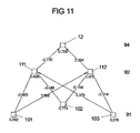
逆進ネットワークを図7〜12に略図的に簡略化して例示するが、このネットワークは、駆動デバイスが窓昇降機を用いて可調コンポーネントとして窓ガラスを調整する力、あるいは窓ガラスの調整動程内にある物体を挟み込み、その結果としてスイッチ−オフまたは逆転値を出力する力を決定するために使用できる。 A reverse network is illustrated schematically in FIGS. 7-12, but this network is the force by which the drive device adjusts the glazing as an adjustable component using a window elevator, or within the adjustment process of the glazing. Can be used to determine the force to pinch an object at and thus output a switch-off or reversal value.
図7は、3つのレイヤ、より詳細には入力レイヤ61、隠れレイヤ62、および出力レイヤ64を伴う逆進ネットワークの第1の入力パターンを示している。入力レイヤ61および隠れレイヤ62に配列されたニューロン101、102、103、111、112は、辺によって、それぞれの上にあるレイヤ62または64に接続されており、それぞれの辺は、それぞれのニューロンに属する重み値を記号化している。
FIG. 7 shows a first input pattern of a reverse network with three layers, more specifically an
入力ニューロン101、102、103に適した値域内に置かれる周期長、モータ電圧、および適応周期についての入力値が入力レイヤ61に印加される。周期長が印加される第1の入力ニューロン101は0.423の重みを有しており、モータ電圧が印加される第2のニューロン102は0.524の重みを有しており、適応周期が印加される第3のニューロン103は0.279の重みを有している。
Input values for a period length, a motor voltage, and an adaptive period placed in a value range suitable for the
隠れレイヤ62は、2つの隠れニューロン111、112を有し、それらには、入力端において入力ニューロン101、102、103の出力が接続されている。第1の隠れニューロン111は、入力ニューロン101、102、103の出力に、接続重み−0.893、−3.446、および3.376を伴う接続を用いて接続されている。第2の隠れニューロン112は、入力ニューロン101、102、103の出力に、接続重み3.869、3.376、および−0.514を伴う接続を経由して接続されている。
The hidden
出力レイヤ64は、出力ニューロン12によって例示されている。この出力値のレベルは、窓昇降機の逆転または動作の継続によるスイッチ−オフ値のために後に決定的となり、その値は、それぞれの電圧について設定される。
それに加えて、より高いレベルにおける隠れレイヤ62および出力レイヤ64のニューロン111、112、および12は、スレッショルド値またはバイアス値を有しており、それが伝達関数の出力を一定の領域内にシフトする。バイアス値および重みは、適用あるいは一連の使用において変更ないしは再学習されない定数である。それらは、一連の使用の前に一度決定され、たとえば、EEPROM内にストアされる。アルゴリズム内に弱点が明らかになった場合には、新しいパラメータを設定すること、すなわち再学習によってそれを改善することができる。しかしながら適用においては、これらの重みが残存する。
In addition, the hidden
学習段階においては、ニューラル・ネットワークに入力パターンが示され、関連する定義済み出力値があらかじめ定められる。この所定の出力が、それぞれの重みならびにバイアス値を伴うニューラル・ネットワークによって計算された出力値と異なるほど、重みおよびバイアス値が変化する。これに関連して、たとえば次に示す特定のパラメータが選択される:
− 増加する周期を伴う窓昇降機の動作間の電圧のジャンプ、落ち込み電圧、および適応周期の決定であり、ニューラル・ネットワークがこの場合に力を検出できないことから0の関連出力値を伴う;
− クリップ−オン力測定計器を用いた、ニューラル・ネットワークのための出力値としてクリップ−オン力測定計器からのフィードバック力を伴うクリップ動作であり、増加する周期長、落ち込み電圧、および適応周期を伴う;
− 種々のばね定数の学習、たとえば20N/mmおよび2N/mm等。
In the learning phase, the input pattern is shown on the neural network and the associated predefined output values are predetermined. The weight and bias values change as this predetermined output differs from the output value calculated by the neural network with the respective weight and bias values. In this context, for example, the following specific parameters are selected:
-Determination of voltage jumps, drop voltage, and adaptation period between window elevator operations with increasing period, with an associated output value of 0 since the neural network cannot detect force in this case;
-Clipping with clip-on force measurement instrument with feedback force from clip-on force measurement instrument as output value for neural network using clip-on force measurement instrument, with increasing period length, drop voltage, and adaptive period ;
-Learning of various spring constants, such as 20 N / mm and 2 N / mm.
それぞれの入力パターンに関連付けされる出力値は、図8に例示されており、ニューロン111、112、および12に書き込まれている第1の隠れニューロン111用のバイアス値2.536、第2の隠れニューロン112用の−0.389をはじめ、出力ニューロン12用の0.775、重み、伝達関数および入力値を用いて決定される。出力値は次のとおりに決定される:それぞれの計算された出力値は、図7、10、11、および12の出力ニューロン12または隠れニューロン111、112の下に示されている。
The output values associated with each input pattern are illustrated in FIG. 8, and the bias value 2.536 for the first
最初に、第1の隠れニューロン111の出力が次のとおりに決定される:
Σ=バイアス(i)+wij×入力(j)
Initially, the output of the first
Σ = bias (i) + wij × input (j)
iは次に高いレイヤ内のi番目のニューロンであり、wは重み、jは入力レイヤ61についてのカウント変数である。重みは入力値に乗じられて合計され、それから第1の隠れニューロン111が次のとおりに得られる:
Σ111=0.423×(−0.893)+0.524×(−3.446)+0.279×3.376+2.536=1.294
i is the i-th neuron in the next higher layer, w is the weight, and j is the count variable for the
Σ 111 = 0.423 × (−0.893) + 0.524 × (−3.446) + 0.279 × 3.376 + 2.536 = 1.294
この合計が、続いて伝達関数に挿入される。ここで使用される伝達関数は、ハイパボリック・タンジェントである。これが、第1の隠れニューロン111の出力値を提供する:
出力111=0.859
This sum is subsequently inserted into the transfer function. The transfer function used here is a hyperbolic tangent. This provides the output value of the first hidden neuron 111:
Output 111 = 0.859
第2の隠れニューロン112の出力値は次のとおりに得られる:
Σ112=0.423×3.869+0.524×(−0.164)+0.279×(−0.514)−0.389=1.018
出力112=TANH(1.018)=0.77
The output value of the second
Σ 112 = 0.423 × 3.869 + 0.524 × (−0.164) + 0.279 × (−0.514) −0.389 = 1.018
Output 112 = TANH (1.018) = 0.77
出力ニューロン12の出力値は次のとおりに得られる:
Σ12=0.77×2.094+0.859×(−2.733)+0.775=0.037
または、出力=TANH(0.037)=0.037
The output value of the
Σ 12 = 0.77 × 2.094 + 0.859 × (−2.733) + 0.775 = 0.037
Or output = TANH (0.037) = 0.037
図7に例示されている最初の入力パターンにおいては、周期長についての値が0.423、電圧についての値が0.524であり、これは10Vの電圧に対応する。適応周期は、より低い値であり、具体的には0.279である。 In the first input pattern illustrated in FIG. 7, the value for the period length is 0.423 and the value for the voltage is 0.524, which corresponds to a voltage of 10V. The adaptation period is a lower value, specifically 0.279.
次に、図10、11、および12に略図的に例示されている3つの追加の入力パターンについて考察する。 Next, consider three additional input patterns schematically illustrated in FIGS.
図9に例示されている第2の入力パターンは、図7に例示されている入力パターンと、大きくは0.423に対する1.001の周期長によって異なり、電圧および適応周期は、ほぼ一定にとどまり、それぞれ0.456および0.277である。同様に、隠れニューロン111、112が入力ニューロン101、102、103の出力に接続される接続の重みをはじめ、隠れニューロン111、112、および出力ニューロン12のバイアス値にも変更がない。
The second input pattern illustrated in FIG. 9 differs from the input pattern illustrated in FIG. 7 largely by a cycle length of 1.001 with respect to 0.423, and the voltage and adaptive period remain almost constant. , 0.456 and 0.277, respectively. Similarly, the bias values of the
この結果は、図7を参照して説明したとおり、第1の隠れニューロン111についての出力値が0.75、第2の隠れニューロン112について0.997、同様に出力ニューロン12について0.67となる。
As described with reference to FIG. 7, the result is that the output value for the first
図10に例示されている第3の入力パターンは、電圧値が16Vと仮定されており、0.824の入力値を伴う。周期長は0.245であり、適応周期は、わずかに修正されて0.261である。この結果として出力ニューロン12の、この入力パターンから挟み込みが検出されない出力値は0.241となる。しかしながらこの種の入力パターンは、挟み込みパターンと区別が可能であり、図12の逆進ネットワークの概略的な例示によって明らかにする。
The third input pattern illustrated in FIG. 10 assumes a voltage value of 16V and involves an input value of 0.824. The period length is 0.245 and the adaptation period is slightly modified to 0.261. As a result, the output value of the
図11に従った入力パターンにおいては、モータ電圧がわずかに下がって値0.774になっているが、周期長は、対応する値と比較すると0.245から0.382に増加している。 In the input pattern according to FIG. 11, the motor voltage slightly decreases to a value of 0.774, but the cycle length increases from 0.245 to 0.382 compared to the corresponding value.
図12aおよび12bには2つのグラフが例示されているが、これらは、図7および9をはじめ10および11に例示されているニューラル・ネットワークの学習の成功を、図7および9はもとより10および11にあらかじめ定義された入力パターンをはじめ電圧値10Vおよび16Vについてグラフ的に例示している。図9および11に従った逆進ネットワークから結果として得られるあらかじめ定義済みの学習値が、それぞれ太い連続線のあらかじめ定義済みの挟み込み力の形式で例示されており、図7および10の逆進ネットワークに従ったそれぞれの入力パターンから結果として得られる出力値が、細い連続曲線表現によって示されている。 FIGS. 12a and 12b illustrate two graphs, which show the successful learning of the neural network illustrated in FIGS. 7 and 9 and 10 and 11, with 10 and 10 as well as FIGS. 11 graphically illustrates voltage values of 10 V and 16 V including a predefined input pattern. The pre-defined learning values resulting from the reverse network according to FIGS. 9 and 11 are illustrated in the form of pre-defined pinching forces with thick continuous lines, respectively, and the reverse network of FIGS. 7 and 10 The resulting output value from each input pattern according to the is represented by a thin continuous curve representation.
図13は、図1に従った駆動モータ3の異なる端子電圧についてポジション依存適応値を決定するためのニューラル適応ネットワーク9の構造を示しており、出力レイヤ94が図2に従ったニューラル・ネットワークの入力レイヤ61に対する出力電圧基準値を出力する独立のニューラル・ネットワークとして考えられている。これは、特定の時間に駆動モータに印加される電圧が基準電圧から異なる場合であっても、瞬時の駆動モータの振る舞いに独特の基準電圧の参照曲線を決定する関数を有している。
FIG. 13 shows the structure of a
図2に従ったニューラル・ネットワーク6の入力ニューロン10は、駆動デバイスの調整力または過剰力に対応する出力値、または挟み込みありもしくは挟み込みなしの状態に対応する出力値を決定するために、ポジションの関数として、図13に従ったニューラル適応ネットワーク9によって出力レイヤ94内で出力される適応値を受け取り、その結果、図2に従ったニューラル・ネットワーク6のこの入力が、現在存在するシフト力、駆動システムの動きにくさ、または動き易さに関する情報としての要求を満たす。それに加えて、この情報は、図2に従った窓ガラス・シール内への窓ガラス22の嵌り込みについて、全システムをより鋭敏でなくするためにも使用される。
The
それぞれの電圧値に対する適応のために、電圧U1における回転速度に対応するn1、電圧U2における回転速度に対応するn2を用いて式:
n1/n2=U1/U2
が使用される場合には、基準電圧上に補間される結果が、絶対システムにとっては不正確に過ぎるものとなり、モータのタイプに非常に大きく依存することになる。したがって、ニューラル適応ネットワークは、特定の駆動モータに対してトレーニングされ、周期および現在電圧から、基準電圧におけるトルクについて定義される基準周期を計算する。この基準周期は、ポジション依存であり、上位となる図2に従ったニューラル・ネットワーク6によってそれぞれの次の調整動作のための、すなわち次の窓移動操作のための入力値として使用される。
For adaptation to the respective voltage values, n 1 corresponding to the rotational speed of the voltage U 1, using n 2 corresponding to the rotational speed of the voltage U 2 wherein:
n 1 / n 2 = U 1 /
If is used, the result interpolated onto the reference voltage will be too inaccurate for an absolute system and will be very dependent on the type of motor. Thus, the neural adaptive network is trained for a particular drive motor and calculates a reference period defined for torque at the reference voltage from the period and the current voltage. This reference period is position dependent and is used as an input value for each subsequent adjustment operation, ie for the next window movement operation, by the
上記の公式を用いた直接変換の間の誤りは10〜15%帯となるが、計算が適応ネットワークを用いて行われるときに生じる誤りは最大で4%であり、特性曲線が曲がっていないときには、最大でも2%帯になる。12%帯の誤りが、全体としてシステム内に2N/mmのばね定数が存在するときには40Nの力の差を、10N/mmのばね定数が存在するとき18Nの力の差をもたらすことから、この増加した精度は、図2に従ったニューラル・ネットワーク6による調整力の決定時における精度に利益を有する。この結果、ニューラル適応ネットワークが使用される場合には、低いばね定数についての力の変動が最大で7Nとなり、比較的高い10N/mmのばね定数についての力の変動が最大で3Nとなる。
The error during direct conversion using the above formula is in the 10-15% band, but the error that occurs when the calculation is performed using an adaptive network is a maximum of 4%, and when the characteristic curve is not bent The maximum is 2%. This is because the 12% band error results in a force difference of 40 N when a spring constant of 2 N / mm is present in the system as a whole, and a force difference of 18 N when a spring constant of 10 N / mm is present. The increased accuracy has a benefit to the accuracy in determining the adjustment force by the
図13に一例として示されているニューラル適応ネットワーク9は、独立のニューラル・ネットワークを構成する。これは、ニューラル・ネットワーク6と同様に、レイヤ91、92、94内に配列されたニューロン30、31、32、33、34、35のセット、および重み付き接続36、37から駆動デバイスの調整力もしくは過剰力、または挟み込みありもしくは挟み込みなしの状態に対応する出力値を決定するために存在し、図2に従ったニューラル・ネットワーク6に関して前述した制限および補足を適用するための方向性グラフの構造を有する。
The neural
最良の学習結果が得られるまで経験的に決定されるニューラル適応ネットワーク9は、最下位レイヤまたは入力レイヤ91内に2つの入力ニューロン30、31を有し、これらのニューロン30、31は、異なる重みを伴って周期長および駆動モータ電圧の入力信号を指定する。周期長に対応する入力ニューロン30は、随意的に4、8、12周期からなる平均値を、たとえば、駆動モータの環状マグネットの非対称性を補償するために構成することが可能であり、駆動モータの電圧に対応する入力ニューロン31は、現在のフィルタリング後の電圧値をそれぞれ表す。
The neural
駆動モータの各四半回転に対応する周期長および電圧の両方が常に存在することから、高いクロック周波数で動作する適応手段が必要な値を常に利用可能であり、これらの値は、駆動モータの完全な回転に同期される必要はない。ニューラル適合ネットワーク6の出力値は、調整されるべきコンポーネントのポジションが駆動モータの1回転によって変更されていない場合に使用される。
Since there is always both a period length and a voltage corresponding to each quarter rotation of the drive motor, the values required by the adaptive means operating at high clock frequencies are always available, and these values are the complete values of the drive motor. There is no need to synchronize with the correct rotation. The output value of the
入力レイヤ91の各入力ニューロン30、31は、隠れレイヤ92の3つの隠れニューロン32、33、34に、複数の接続36によって接続されており、それらには異なる重みが割り当てられている。隠れレイヤ92の3つの隠れニューロン32、33、34は、異なる正および負の重みを有し、かつ出力レイヤ94の出力ニューロン35に、複数の正または負の重みを有する接続によって接続されており、適応周期は、入力値から決定され、出力レイヤ94に存在する基準周波数に対して標準化される。
Each
図13に例示されている多段ニューラル適応ネットワーク9のニューロンの入力ならびに接続の重み付けは、学習段階において第1の値が経験的にあらかじめ定義された後に行われ、それにおいては新しい接続が開発され、既存の接続が削除され、接続の強さが重みの変更によって修正され、スレッショルド値ならびに伝達関数が修正され、新しいニューロンが開発され、既存のニューロンが削除される。重みおよびバイアスは、ニューラル適応ネットワークのインテリジェンスを構成し、2つの極端な電圧、たとえば9および16Vの間の駆動モータの振る舞いをモデリングする。
The weighting of the inputs and connections of the neuron of the multi-stage
ネットワークの重みを決定するためのすべての可能トルクにおいて最適な方法で駆動モータの振る舞いをトレーニングするために、駆動モータが、トルク用の信号を供給するエンジン・ブレーキにクランプされる。駆動モータは、電子システムを用いて動作され、電圧および周期が読み出される。この情報がトルクと同期されて記録され、各電圧における吸収作用が、駆動システムの遮断までアイドリング速度において行われる。駆動モータが再冷却されるように、より長い間隔が各測定間に挿入される。 In order to train the drive motor behavior in an optimal manner at all possible torques for determining the network weight, the drive motor is clamped to an engine brake that provides a signal for torque. The drive motor is operated using an electronic system and the voltage and period are read out. This information is recorded in synchronism with the torque and absorption at each voltage takes place at idling speed until the drive system is shut off. Longer intervals are inserted between each measurement so that the drive motor is re-cooled.
異なる気候条件の下に精度の向上が求められるときには、同じ駆動モータが、モータ温度自体を一定に維持したまま異なる温度で動作される。それに代わる場合には、それがニューラル適応ネットワークのための追加の可能入力として役立つ。モータ温度は、ニューラル温度ネットワークを用いて、アイドリング速度および電圧によって決定することもできる。このようにして決定されるモータ温度は、乗り物の外側にマウントされる温度センサより高精度であることから、駆動モータの温度保護にも使用することが可能である。 When improved accuracy is required under different climatic conditions, the same drive motor is operated at different temperatures while keeping the motor temperature itself constant. In the alternative, it serves as an additional possible input for the neural adaptive network. The motor temperature can also be determined by idling speed and voltage using a neural temperature network. Since the motor temperature determined in this manner is more accurate than a temperature sensor mounted outside the vehicle, it can be used for temperature protection of the drive motor.
図13および14は、ニューラル適応ネットワーク9の精度を立証するために、9Vおよび16Vのモータ電圧について基準周期を決定する2つの例を示している。それぞれの場合に、各トルクにおいて、ニューラル適応ネットワークのポジション依存適応値が以下のとおりに計算される:
入力1=周期 入力2=電圧
場合1:9V 0.946065 0.379684
場合2:16V 0.415552 0.691795
バイアス1(接続ニューロン32) 1.17752
バイアス1(接続ニューロン33) −2.35308
バイアス1(接続ニューロン34) −0.09405
バイアス1(出力ニューロン) −3.15073
FIGS. 13 and 14 show two examples of determining the reference period for motor voltages of 9V and 16V in order to verify the accuracy of the neural
Case 2: 16V 0.415552 0.6917995
Bias 1 (connected neuron 32) 1.17752
Bias 1 (connected neuron 33) -2.335308
Bias 1 (Connecting neuron 34) -0.09405
Bias 1 (output neuron) -3.15073
たとえばロジスティック関数が伝達関数として使用される:
出力i=1/(1+exp(−(合計i+バイアスi)))
For example, a logistic function is used as a transfer function:
Output i = 1 / (1 + exp (− (total i + bias i )))
第1の隠れニューロン32の合計は:
合計1=入力1×重み11+入力2×重み12+バイアス1=0.946065×(−4.766)+0.379684×0.006+1.17752=−3.3291
The sum of the first
Total 1 =
第1の隠れニューロン32の出力値は、したがって次のとおりとなる:
出力i=1/(1+exp(−(−3.3291)))=0.034586
The output value of the first hidden
Output i = 1 / (1 + exp (− (− 3.3291))) = 0.034586
この結果が、図13に例示されているニューラル適応ネットワークの第1の隠れニューロン32の下に、丸められた形式で与えられている。
This result is given in rounded form below the first hidden
この手順に従って、第2および第3の隠れニューロン32、34、および出力ニューロン35の出力値を計算することができる:
合計2=−0.3055108
出力2= 0.42421088
合計3= 1.56893044
出力3= 0.82763108
合計4=−0.9786242
出力4= 0.27316486=9Vにおける結果
According to this procedure, the output values of the second and third
Total 2 = -0.30555108
Output 2 = 0.42421088
Total 3 = 1.56993044
Output 3 = 0.827663108
Total 4 = -0.9786242
Result at output 4 = 0.27316486 = 9V
同じ方法において、このニューラル適応ネットワークを用いて16Vのモータ電圧の場合の基準周期を次のとおりに計算することができる:
合計1=−0.7989789
出力1= 0.31024398
合計2= 0.93062225
出力2= 0.71720151
合計3= 0.81829026
出力3= 0.69387329
合計4=−0.9684947
出力4= 0.27518065=16Vにおける結果
In the same way, using this neural adaptive network, the reference period for a motor voltage of 16V can be calculated as follows:
Total 1 = -0.79798789
Output 1 = 0.31024398
Total 2 = 0.93062225
Output 2 = 0.71720151
Total 3 = 0.81829026
Output 3 = 0.69387329
Total 4 = -0.9684947
Result at output 4 = 0.27518065 = 16V
上に示した外部電圧値に関する誤り率は、次のとおりとなる:
1−0.27518065/0.27316486=0.73%
The error rates for the external voltage values shown above are as follows:
1-0.27518065 / 0.27316486 = 0.73%
近似n1/n2=U1/U2を用いて生じる誤りは駆動モータに依存するが、後者になぞらえると10から15%までの間となる。 The error that occurs with the approximation n 1 / n 2 = U 1 / U 2 depends on the drive motor, but is between 10 and 15% when compared to the latter.
たとえば窓昇降システムの調整力における変化、あるいは駆動モータ内の変化に起因する駆動モータの不適切な逆転を避けるために、挟み込まれた物体のばね定数を、挟み込みプロセスの検出のための追加の判断基準として考慮に入れる。 To avoid improper reversal of the drive motor, for example due to changes in the adjustment of the window lift system or changes in the drive motor, the spring constant of the pinched object is an additional decision for detecting the pinching process Take into account as a reference.
駆動モータが、たとえば4極リング・マグネットを有している場合には、駆動モータの周期ゼロと周期4の間における回転速度の差が決定され、この値が図2に従って、駆動デバイスの調整力に対応するニューラル・ネットワーク6の出力値と論理的に結合される。この論理動作の方法について、図15〜17を参照してより詳細に説明する。
If the drive motor has, for example, a quadrupole ring magnet, the difference in rotational speed between cycle zero and
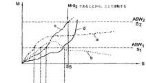
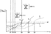
図15は、4つの窓閉めプロセスa〜dについて調整動程sに対してプロットしたトルクMのプロファイルを示しており、図16は、ばね定数Frのプロファイルおよび図1に従った窓ガラス22の窓閉め動作(図15に例示)について調整動程sにわたる2つの比較周期の回転速度における差のプロファイルを示している。回転速度における差のためのスレッショルド値SFは、ここでは低いばね定数が開始する限界を定義し、たとえば20N/mmとする。
FIG. 15 shows the profile of torque M plotted against the adjustment travel s for the four window closing processes a to d, FIG. 16 shows the profile of the spring constant Fr and the
ニューラル・ネットワークの出力値の2つのスイッチ−オフ値スレッショルド値ASW1およびASW2および回転速度における差のためのスレッショルド値SFをあらかじめ定義することは、以下に述べる逆転の場合の区別を可能にする。 Predefining the threshold value SF for the difference between the two switch-off value threshold values ASW 1 and ASW 2 and the rotational speed of the output value of the neural network enables the distinction in the case of reversal described below. .
ニューラル・ネットワークの出力値Mが、曲線aに従って調整動程s1の後に第1のスイッチ−オフ・スレッショルド値ASW1を超え、かつ回転速度における差が、このポイントにおいて回転速度における差のためのあらかじめ定義済みのスレッショルド値SFより小さい場合には、駆動モータは、その先の過程内で回転速度における差のためのあらかじめ定義済みのスレッショルド値SFを、たとえば調整動程s7の後に超えることがあっても逆転されない。 The output value M of the neural network exceeds the first switch-off threshold value ASW 1 after the adjustment stroke s 1 according to the curve a, and the difference in rotational speed is due to the difference in rotational speed at this point. advance if the predefined threshold value SF is smaller than the drive motor, a predefined threshold value SF for the difference in rotational speed in the course of the above, for example, be exceeded after the adjustment throw s 7 Even if there is, it is not reversed.
この場合、その先の過程内で回転速度における差のためのスレッショルド値SFを超えたときに、駆動モータを逆転することが可能でなくなるように、駆動モータの逆転がロックされるかブロックされる。その先の調整プロセスの間に第2のスイッチ−オフ・スレッショルド値S2を超えた場合に限り、駆動モータの即時の逆転が生じる。 In this case, the reverse rotation of the drive motor is locked or blocked so that it is no longer possible to reverse the drive motor when the threshold value SF for the difference in rotational speed is exceeded in the previous process. . Only if the second switch-off threshold value S2 is exceeded during the further adjustment process, an immediate reversal of the drive motor occurs.
このパスの間に、第1のスイッチ−オフ・スレッショルド値ASW1より大きい第2のスイッチ−オフ・スレッショルド値ASW2を超えた場合に限り、駆動モータが逆転される。 During this pass, the first switch - off threshold value ASW 1 greater than the second switch - only if it exceeds the off threshold value ASW 2, the drive motor is reversed.
同一の判断基準が、調整動程s2の後に第1のスイッチ−オフ・スレッショルド値ASW1をわずかに超え、その後再び第1のスイッチ−オフ・スレッショルド値ASW1の下に下がる曲線bに適用される。 The same criterion applies to curve b which slightly exceeds the first switch-off threshold value ASW 1 after the adjustment stroke s 2 and then falls again below the first switch-off threshold value ASW 1 Is done.
ニューラル・ネットワークの出力値Mが、曲線cに従って調整動程s3の間に第1のスイッチ−オフ・スレッショルド値ASW1を超え、その間、回転速度における差が同様に回転速度における差のためのスレッショルド値SFより小さい場合には、ポイントs5において第2のスイッチ−オフ・スレッショルド値ASW2を超えると直ちに駆動モータが逆転される。 The output value M of the neural network exceeds the first switch-off threshold value ASW 1 during the adjustment stroke s 3 according to the curve c, during which the difference in rotational speed is likewise due to the difference in rotational speed If the threshold value SF is smaller than the second switch at point s 5 - soon drive motor exceeds off threshold value ASW 2 is reversed.
ニューラル・ネットワークの出力値Mが、曲線dに従って調整動程s4の後に第1のスイッチ−オフ・スレッショルド値ASW1を超え、かつ回転速度における差が、このポイントにおいて回転速度における差のためのスレッショルド値SFより大きい場合には、駆動モータが直ちに逆転される。 The output value M of the neural network exceeds the first switch-off threshold value ASW 1 after the adjustment stroke s 4 according to the curve d, and the difference in rotational speed is due to the difference in rotational speed at this point. If it is greater than the threshold value SF, the drive motor is immediately reversed.
図17は、上記のスイッチ−オの判断基準をフローチャートとして例示しており、プログラムの開始後に第1の判断ブロック41において、ニューラル・ネットワークの出力値ANと第1のスイッチ−オフ・スレッショルド値ASW1が比較され、ばね定数または回転速度における差と回転速度における差のためのスレッショルド値SFが比較される。出力値ANが第1のスイッチ−オフ・スレッショルド値ASW1より大きく、かつ回転速度における差が回転速度における差のためのスレッショルド値SFより小さいときにはフラグ44がセットされて第2の判断ブロック42に渡されるが、この条件が満たされないときにはプログラムが直接判断ブロック42に進む。
17, the above switch - exemplifies criteria Oh as a flowchart, in the
この第2の判断ブロック42においては、フラグ42がセットされているか否か、およびニューラル・ネットワークの出力値ANが第2のスイッチ−オフ・スレッショルド値ASW2より大きいか否かについてテストされる。このアンド論理演算が当てはまる場合には、駆動モータが直ちに逆転される。その逆に、この条件が満たされない場合には、第3の判断ブロック43において、ニューラル・ネットワークの出力値ANが第1のスイッチ−オフ・スレッショルド値ASW1より大きいか否か、および回転速度における差が回転速度における差のためのスレッショルド値SFより大きいか否かについてチェックされる。これが当てはまる場合においても駆動モータが直ちに逆転される。これが当てはまらない場合には、システムが再び第1の判断ブロック41に戻る。
In the
決定済みのばね定数とニューラル・ネットワークの出力値の論理的組み合わせは、ファジィ・システムによって、もしくは対応するアルゴリズムを伴う数学モデルによって、あるいは同様に、入力レイヤにおいて図2に従ったニューラル・ネットワークの調整力または調整トルクに対応する出力値が供給され、かつ回転速度における決定済みの差が供給されるニューラル・ネットワークであって、その出力レイヤにおいて挟み込みありもしくは挟み込みなしの状態に対応する値を出力するニューラル・ネットワークによって行われる。 The logical combination of the determined spring constant and the output value of the neural network can be adjusted by a fuzzy system or by a mathematical model with a corresponding algorithm, or likewise at the input layer by adjusting the neural network according to FIG. A neural network to which an output value corresponding to force or adjusting torque is supplied and to which a determined difference in rotational speed is supplied, which outputs a value corresponding to the state of pinching or not pinching in its output layer This is done by a neural network.
図18aは、自動車コンポーネントの調整デバイスのためのニューラル・ネットワークを伴うコントロール・デバイスの第1の実施態様を示した略図的なブロック図である。 FIG. 18a is a schematic block diagram illustrating a first embodiment of a control device with a neural network for an automotive component coordination device.
最初に例示のコントロール・デバイスの設計について説明する。このコントロール・デバイスは、電子デバイス1000を包含する。電子デバイスは、マイクロコントローラ1100、ニューラル・ネットワーク1200を伴うコンポーネント、およびストレージ・エレメント1300を有する。マイクロコントローラ1100は、ニューラル・ネットワーク1200ならびにストレージ・エレメント1300の両方に接続されている。ストレージ・エレメント1300は、ライン接続を介してニューラル・ネットワーク1200とインタラクションする。
First, an exemplary control device design will be described. This control device includes an
マイクロコントローラ1100ならびにニューラル・ネットワーク1200は、ともに複数のインターフェース1400、1500を有する。ニューラル・ネットワーク1200のインターフェース1400は、評価されることになる測定変量S’用の入力としての要求を満たす。インターフェース1400は、測定変量Sをニューラル・ネットワーク1200の入力レイヤに供給する。これらのインターフェース1300のうちの1ないしは複数は、自動車のCANバス・システムまたはLINバス・システムに対する接続として具体化することができる。
Both the
特に、自動車もしくは自動車コンポーネント、たとえばドアまたはテールゲート等の移動の特性を記述する加速度センサは、測定変量S’として適している。これらの加速度信号を基礎として、たとえば自動車が悪路部分を走行する状態、あるいはドアまたはテールゲートが勢いよく閉じられる動きとして明確に識別することが可能になる。同様に、評価されるべき調整デバイスに割り当てられるモータM’の測定変調のための備えもある。電気モータの動作特性は、たとえばホール・センサによって監視することができる。それらの信号の評価は、動きの非容易性および挟み込みの場合について結論を引き出すことを可能にする。 In particular, an acceleration sensor that describes the movement characteristics of an automobile or an automobile component, such as a door or a tailgate, is suitable as a measurement variable S '. On the basis of these acceleration signals, it is possible to clearly identify, for example, a state in which the automobile is traveling on a rough road part, or a movement in which the door or the tailgate is closed rapidly. There is likewise provision for measurement modulation of the motor M 'assigned to the adjusting device to be evaluated. The operating characteristics of the electric motor can be monitored, for example, by a hall sensor. The evaluation of those signals makes it possible to draw conclusions about the inability of movement and the case of pinching.
マイクロコントローラ1100のインターフェース1500は、自動車ならびにそのコンポーネントの種々の状態を読み出すことのできる入力としての要求を満たす。これらは、同一の測定変量Sまたはインターフェース1400を経由してニューラル・ネットワーク1200に供給される測定変量のサブセットS’である。
The
マイクロコントローラ1100は、ライン接続を介し、電力ドライバH’を使用してモータM’をコントロールする。モータM’は、この調整デバイスに割り当てられている自動車コンポーネントを動かす。
The
言うまでもないが電子デバイス1000のエレメントとして例示されたマイクロコントローラ1100、ニューラル・ネットワーク1200、および/またはストレージ・エレメント1300は、集積回路の形式の物理的ユニットとして構成することができる。ニューラル・ネットワーク1200およびストレージ・エレメント1300が集積化される変形については、図18bにコントロール・デバイスの第2の実施態様の略図的な例示として示した。この例示内のそのほかのコンポーネントは、図18aのコンポーネントに対応し、したがって前述を参照されたい。
It will be appreciated that the
マイクロコントローラ内へのニューラル・ネットワークの組み込みの技術的な実装は、一方では、ソフトウエアとしてマイクロコントローラ内にニューラル・ネットワークが実装される形式を取ることができる。他方においては、マイクロコントローラがASIC(特定用途向け集積回路)構造の形式で実装されることも企図されている。当然のことながら、ストレージ・エレメント1300もまた、図18bに示されているとおり、マイクロコントローラ内に実装することができる。考えられる変形(図示せず)の1つでは、ニューラル・ネットワーク1200だけがマイクロコントローラ内に集積化され、電子デバイスの別体のコンポーネントとしてストレージ・エレメントが実装される。
The technical implementation of embedding a neural network in the microcontroller, on the other hand, can take the form of a neural network being implemented in the microcontroller as software. On the other hand, it is also contemplated that the microcontroller is implemented in the form of an ASIC (application specific integrated circuit) structure. Of course, the
次に、図18aおよび18bに例示されているコントロール・デバイスが機能する方法について考察する。マイクロコントローラ1100は、インターフェース1400、1500を介して、自動車ならびにそのコンポーネントの、それぞれの状態についての情報を表す信号を受信する。マイクロコントローラ1100内では、決定された状態のうちのいずれにおいて、いずれの重みのセットの重みを用いてニューラル・ネットワーク1200が動作するべきかについての情報がストアされる。したがって、決定された自動車ならびにそのコンポーネントの状態が、ニューラル・ネットワーク1200のために異なる重みのセットが必要となるような方法で変化した場合には、マイクロコントローラが、ニューラル・ネットワーク1200がストレージ・エレメント1300から対応する重みのセットを利用できるようにするプロセスを開始する。ニューラル・ネットワーク1200は、その後、マイクロコントローラ1100が再び自動車および/またはそのコンポーネントの状態の変化を登録し、その結果、ニューラル・ネットワークのための重みのセットの更新置換が必要となるまで、その新しい重みのセットを用いて動作する。
Next, consider how the control device illustrated in FIGS. 18a and 18b functions. The
上記が機能する方法は、ニューラル・ネットワーク1200がソフトウエアとして、もしくはマイクロコントローラ1100内のASIC設計の集積化されたハードウエア・エレメントとして実装されているか否か、あるいは別体の電子コンポーネントとして備えられているか否かということとは独立している。
The way in which the above works is provided whether the
ニューラル・ネットワーク1200は、自動車コンポーネントの調整動程内に挟み込まれた状態になる障害物のための挟み込み防止手段を、現在のアクティブな重みセットとは独立に提供している。
このようにすれば、特定の状態、たとえば自動車が悪路部分を移動するとき、あるいは自動車のドアが勢いよく閉じられた場合に、調整デバイスのニューラル・ネットワーク1200が自動車の可調コンポーネントのばね定数の限定された範囲を主として検出するようにコントロール・システムを好ましく構成することができる。これは、ニューラル・ネットワーク1200によって実装される挟み込み防止システムの応答スレッショルドの有意の増加が別のばね定数のために使用されることから達成可能となる。
In this way, the
これが略図的に図19に示されている。この図には、ばね定数F’に対して調整デバイスの挟み込み防止システムの応答スレッショルドA’がプロットされている。 This is shown schematically in FIG. In this figure, the response threshold A 'of the regulating device anti-pinch system is plotted against the spring constant F'.
ニューラル・ネットワーク1200の第1の重みセットG1’は、すべてのばね定数F’について同一の応答スレッショルドを有する。実線およびそれに続く鎖線は、これを示すことが意図されている。
The first weight set G1 'of the
第2の重みセットG2’は、約20N/mmのばね定数から応答スレッショルドに有意の増加を有する。このセットG2’は、たとえば悪路部分を移動するとき、あるいは自動車のドアが勢いよく閉じられるといった情況に使用されることになる。応答スレッショルドならびにばね定数のスレッショルド値における増加の絶対値が自在に調整可能なことは明らかであり、例示の矢印には、それを示すことが意図されている。 The second weight set G2 'has a significant increase in response threshold from a spring constant of about 20 N / mm. This set G2 'is used, for example, when moving on a rough road part or in a situation where the door of the automobile is closed vigorously. It is clear that the absolute value of the increase in the response threshold as well as the threshold value of the spring constant can be freely adjusted, and the example arrows are intended to show it.
さらに、ニューラル・ネットワークを有する電子デバイスを伴った自動車コンポーネントの調整デバイスについて説明する。この方法は、次のステップを包含する:
− 自動車および/または調整デバイスの状態を決定するための、自動車および/または調整デバイスの測定変量の電子デバイスによる評価;
− 複数の重みセットからのニューラル・ネットワークのための、測定変量ならびに決定済みの状態の評価の関数としての重みセットの選択;および、
− 自動車コンポーネントの調整デバイスがコントロールされる間におけるニューラル・ネットワークを動作させるために選択した重みセットの使用。
Furthermore, an automotive component coordination device with an electronic device having a neural network is described. This method includes the following steps:
-Evaluation of the measured variables of the motor vehicle and / or adjusting device by an electronic device to determine the state of the motor vehicle and / or adjusting device;
-Selection of weight sets as a function of the evaluation of measured variables and determined states for neural networks from multiple weight sets; and
-Use of the selected weight set to operate the neural network while the automotive component coordination device is controlled.
これに関してニューラル・ネットワークは、自動車コンポーネントの調整動程内に挟み込まれた状態になる障害物のための挟み込み防止手段が利用可能となる態様で好ましくは動作される。 In this regard, the neural network is preferably operated in such a way that an anti-pinch means is available for obstacles that become pinched within the adjustment stroke of the vehicle component.
電子デバイスのマイクロコントローラは、自動車および/または自動車コンポーネントの状態を決定するために好ましく自動車の測定変量を評価する。決定された情況に応じて、マイクロコントローラは、その情況に割り当てられたニューラル・ネットワークのための重みセットをアクティブ化することになる。 The microcontroller of the electronic device preferably evaluates the measured variables of the vehicle to determine the state of the vehicle and / or vehicle component. Depending on the determined situation, the microcontroller will activate the weight set for the neural network assigned to that situation.
1 自動車のドア
2 窓昇降機
3 駆動モータ
4 切り替えデバイス
5 電圧源
6 ニューラル・ネットワーク(逆進ネットワーク)
7 オペレータ・コントロール・ユニット
8 マイクロコンピュータ
9 ニューラル適応ネットワーク
10 入力ニューロン
11 隠れニューロン
12 出力ニューロン
14,15,16 重み付き接続
21 昇降レール
22 窓ガラス
23 昇降デバイス
30,31 ニューラル適応ネットワークの入力ニューロン
32,33,34 ニューラル適応ネットワークの隠れニューロン
35 ニューラル適応ネットワークの出力ニューロン
36,37 ニューラル適応ネットワークの重み付き接続
60 マイクロプロセッ
61 入力レイヤ
62,63 隠れレイヤ
64 出力レイヤ
91 ニューラル適応ネットワークの入力レイヤ
92,93 ニューラル適応ネットワークの隠れレイヤ
94 ニューラル適応ネットワークの出力レイヤ
101〜103 入力ニューロン
111,112 隠れニューロン
1000 電子デバイス
1100 マイクロコントローラ
1200 ニューラル・ネットワーク
1300 ストレージ・ユニット
1400,1500 インターフェース
A’ 挟み込み防止手段の応答スレッショルド
F’ ばね定数
G1’ ニューラル・ネットワークに対する第1の重みセット
G2’ ニューラル・ネットワークに対する第2の重みセット
H’ 電力ドライバ
M’ モータ・デバイス
S’ 測定変量
ASW1,ASW2 スイッチ−オフ・スレッショルド値
SF 回転速度における差に対するスレッショルド値
DESCRIPTION OF
7
Claims (27)
− ランダムな重みが割り当てられること、
− 前記入力ニューロン(10;101,102,103)に印加される様々な入力パターンがあらかじめ定められており、関連する少なくとも1つの出力値が計算されること、および
− 重みおよび/またはスレッショルド値が、前記少なくとも1つの出力値と少なくとも1つのセットポイント出力値との間の差の関数として変更されること、
を特徴とする、請求項1〜6の少なくとも1つに記載の方法。 In the learning phase, in the input neurons (10; 101, 102, 103), hidden neurons (11; 111, 112) and / or output neurons (12) of the neural network (6),
-Random weights are assigned,
-Various input patterns applied to said input neurons (10; 101, 102, 103) are predetermined, at least one associated output value is calculated, and-weights and / or threshold values are Being changed as a function of the difference between the at least one output value and the at least one setpoint output value;
A method according to at least one of the preceding claims, characterized in that
− 直進形式で調整可能な前記コンポーネントの適応プロファイルの値、
− 直進形式で調整可能な前記コンポーネントが調整されるときの適応周期の値、
− 増速フラグ、
− 前記駆動モータの端子電圧のためのシフト・レジスタの出力値、
− 周期値のためのシフト・レジスタの出力値、
− 前記駆動モータの温度、
− 周囲温度、
− 速度信号、
− 振動電圧、および
− 先行する出力値、
からなり、かつニューラル手段によって決定される力が、出力ニューロンの出力として出力されることを特徴とする、請求項1〜12の少なくとも1つに記載の方法。 The input value of the input neuron (10; 101, 102, 103) is
The value of the adaptive profile of said component, adjustable in straight-line form,
The value of the adaptive period when the component adjustable in straight form is adjusted;
-Acceleration flag,
The output value of the shift register for the terminal voltage of the drive motor,
The output value of the shift register for the period value,
The temperature of the drive motor,
− Ambient temperature,
-Speed signal,
-Oscillating voltage, and-preceding output value,
A method according to at least one of the preceding claims, characterized in that the force consisting of and determined by the neural means is output as the output of the output neuron.
− 前記ニューラル・ネットワーク(6)の前記出力値および回転速度における差に対する所定のスレッショルド値(SF)より小さい回転速度における差の第1のスイッチ−オフ・スレッショルド値(ASW1)が超えられたときに、前記駆動モータ(3)が停止されるか、あるいは前記ニューラル・ネットワーク(6)の出力値が前記第1のスイッチ−オフ・スレッショルド値(ASW1)より大きい第2のスイッチ−オフ・スレッショルド値(ASW2)を超えた場合に限り前記調整動作の終わりまで逆転され、
− 前記ニューラル・ネットワーク(6)の前記出力値の第1のスイッチ−オフ・スレッショルド値(ASW1)および回転速度における差に対する所定のスレッショルド値(SF)より大きい回転速度における差が超えられたときに、前記駆動モータ(3)が停止されるか、あるいは逆転され、
− 前記第2のスイッチ−オフ・スレッショルド値(ASW2)が超えられたときには前記回転速度における差に関係なく、前記駆動モータ(3)が停止されるか、あるいは逆転されるように論理的に結合されることを特徴とする、請求項23もしくは24に記載の方法。 The rotational speed of the drive motor (3) is detected, the difference in rotational speed between the two periods is determined, the output value of the neural network (6),
The first switch-off threshold value (ASW 1 ) of the difference at a rotational speed less than a predetermined threshold value (SF) for the difference in the output value and rotational speed of the neural network (6) is exceeded In addition, the drive motor (3) is stopped or the output value of the neural network (6) is greater than the first switch-off threshold value (ASW 1 ). Only when the value (ASW 2 ) is exceeded, it is reversed until the end of the adjustment operation,
-A first switch of the output value of the neural network (6)-when a difference in rotational speed greater than a predetermined threshold value (SF) relative to the difference in off-threshold value (ASW1) and rotational speed is exceeded The drive motor (3) is stopped or reversed,
-The second switch-logically so that when the off-threshold value (ASW2) is exceeded, the drive motor (3) is stopped or reversed regardless of the difference in the rotational speed 25. A method according to claim 23 or 24, characterized in that they are combined.
前記入力信号の評価および前記決定された状態とは関わりなく複数の重みセットから前記ニューラル・ネットワークのための重みセットを選択するステップ;および、
前記選択した重みセットを使用して、前記調節可能なコンポーネントの前記駆動デバイスがコントロールされる際に前記ニューラル・ネットワークを作動させるステップ;
を有する、請求項1〜25の少なくとも1つに記載の方法。 Evaluating an input signal by the neural network to determine the state of the vehicle and / or the state of the conditioning device;
Selecting a weight set for the neural network from a plurality of weight sets regardless of the evaluation of the input signal and the determined state; and
Activating the neural network when the driving device of the adjustable component is controlled using the selected weight set;
26. A method according to at least one of claims 1 to 25, comprising:
Applications Claiming Priority (2)
| Application Number | Priority Date | Filing Date | Title |
|---|---|---|---|
| DE102004011015A DE102004011015A1 (en) | 2004-03-02 | 2004-03-02 | Monitoring displacement, especially of vehicle window or sliding roof, involves feeding signals representing drive device deceleration to neural network with buried layer(s) that outputs displacement force or jammed/non-jammed state value |
| PCT/DE2005/000360 WO2005086312A1 (en) | 2004-03-02 | 2005-03-02 | Method for monitoring the adjustment movement of a component driven by a driving device |
Publications (2)
| Publication Number | Publication Date |
|---|---|
| JP2007526735A true JP2007526735A (en) | 2007-09-13 |
| JP2007526735A5 JP2007526735A5 (en) | 2008-04-17 |
Family
ID=34853955
Family Applications (1)
| Application Number | Title | Priority Date | Filing Date |
|---|---|---|---|
| JP2007501108A Pending JP2007526735A (en) | 2004-03-02 | 2005-03-02 | Method for monitoring the adjustment behavior of a component driven by a driving device |
Country Status (6)
| Country | Link |
|---|---|
| US (1) | US8068958B2 (en) |
| EP (1) | EP1726076B1 (en) |
| JP (1) | JP2007526735A (en) |
| AT (1) | ATE527735T1 (en) |
| DE (1) | DE102004011015A1 (en) |
| WO (1) | WO2005086312A1 (en) |
Families Citing this family (16)
| Publication number | Priority date | Publication date | Assignee | Title |
|---|---|---|---|---|
| JP2007063889A (en) * | 2005-09-01 | 2007-03-15 | Asmo Co Ltd | Opening-closing member control device and its control method |
| DE102006016187A1 (en) * | 2006-04-06 | 2007-10-11 | Bayerische Motoren Werke Ag | Automatic motor vehicle closing system e.g. electrical sun roof, quality evaluating method for introducing e.g. fault-diagnosis, involves determining data set from integrated vehicle closing systems |
| DE102006023330B4 (en) | 2006-05-11 | 2015-09-03 | Brose Fahrzeugteile Gmbh & Co. Kommanditgesellschaft, Coburg | Method and device for adjusting a frameless window pane of a motor vehicle |
| DE102007001026B4 (en) | 2007-01-02 | 2008-09-04 | Siemens Ag | Method for computer-aided control and / or regulation of a technical system |
| DE102008039146B4 (en) * | 2007-08-28 | 2014-02-20 | Asmo Co., Ltd. | Control unit for a locking panel |
| DE102008020379A1 (en) | 2008-04-23 | 2009-10-29 | Siemens Aktiengesellschaft | Method for computer-aided control and / or regulation of a technical system |
| DE102012106927A1 (en) * | 2012-07-30 | 2014-01-30 | Brose Fahrzeugteile Gmbh & Co. Kg, Hallstadt | Method for functional testing of an anti-pinch system and diagnostic device |
| DE102017218428B3 (en) | 2017-10-16 | 2019-01-31 | Conti Temic Microelectronic Gmbh | Method for operating a closing device of a motor vehicle and closing device of a motor vehicle |
| US10774574B2 (en) | 2018-03-26 | 2020-09-15 | Honda Motor Co., Ltd. | Operation of vehicle power doors |
| JP6505342B1 (en) | 2018-07-06 | 2019-04-24 | 三菱電機株式会社 | Machine learning apparatus, numerical control apparatus, machine tool and machine learning method |
| RU186950U1 (en) * | 2018-09-25 | 2019-02-11 | Федеральное государственное автономное образовательное учреждение высшего образования "Санкт-Петербургский государственный электротехнический университет "ЛЭТИ" им. В.И. Ульянова (Ленина)" | Control device for electric drive of nonlinear objects based on neural networks |
| JP6661062B1 (en) | 2018-12-28 | 2020-03-11 | 三菱電機株式会社 | Numerical control device and machine learning device |
| KR20210137536A (en) * | 2019-03-19 | 2021-11-17 | 파나소닉 아이피 매니지먼트 가부시키가이샤 | Motor control method, motor control model conversion method, motor control system, motor control model conversion system, and motor control model conversion program |
| RU193607U1 (en) * | 2019-05-28 | 2019-11-06 | Федеральное государственное автономное образовательное учреждение высшего образования "Санкт-Петербургский государственный электротехнический университет "ЛЭТИ" им. В.И. Ульянова (Ленина)" | A device for controlling an electric drive of an object under the influence of external disturbances based on neural networks |
| CN111573092B (en) * | 2020-04-02 | 2022-01-14 | 国网浙江省电力有限公司湖州供电公司 | Liftable formula cable frame |
| CN112366998B (en) * | 2020-11-06 | 2023-04-07 | 珠海格力电器股份有限公司 | Motor control method, device and system |
Citations (4)
| Publication number | Priority date | Publication date | Assignee | Title |
|---|---|---|---|---|
| JPH0610561A (en) * | 1992-06-26 | 1994-01-18 | Omron Corp | Method and device for controlling opening and closing motion of window |
| JPH06217597A (en) * | 1993-01-18 | 1994-08-05 | Toyota Motor Corp | Step motor controller |
| JP2002106258A (en) * | 2000-10-04 | 2002-04-10 | Matsushita Electric Ind Co Ltd | Catch determination device and opening/closing device |
| JP2002295129A (en) * | 2001-04-02 | 2002-10-09 | Yazaki Corp | Power window insertion preventive device |
Family Cites Families (17)
| Publication number | Priority date | Publication date | Assignee | Title |
|---|---|---|---|---|
| DE4020351A1 (en) * | 1990-06-27 | 1992-01-09 | Kostal Leopold Gmbh & Co Kg | Electronically monitoring and controlling window winder - using additional body motion sensor to avoid false triggering of unit in motor vehicle |
| JP2974440B2 (en) * | 1991-03-22 | 1999-11-10 | 株式会社日立製作所 | Automotive integrated control device |
| JP3169635B2 (en) * | 1991-07-03 | 2001-05-28 | 本田技研工業株式会社 | Neural network and learning method thereof |
| ES2105229T3 (en) | 1992-03-23 | 1997-10-16 | Stefan Battlogg | WINDSHIELD WIPER INSTALLATION. |
| JPH06131188A (en) * | 1992-10-22 | 1994-05-13 | Hitachi Ltd | Fuzzy rule acquisition method and fuzzy inference system |
| US5828812A (en) * | 1993-03-24 | 1998-10-27 | National Semiconductor Corporation | Recurrent neural network-based fuzzy logic system and method |
| US5991675A (en) * | 1993-06-02 | 1999-11-23 | Honda Giken Kogyo Kabushiki Kaisha | Vehicle control system based on estimation of the driving skill of a vehicle operator |
| DE19527323A1 (en) | 1995-07-26 | 1997-01-30 | Siemens Ag | Circuit arrangement for controlling a device in a motor vehicle |
| US5982124A (en) * | 1995-08-30 | 1999-11-09 | Trw Inc. | Method and apparatus for adaptive control of a vehicle power window |
| US6330553B1 (en) * | 1997-04-09 | 2001-12-11 | Yamaha Hatsudoki Kabushiki Kaisha | Autonomic system for updating fuzzy neural network and control system using the fuzzy neural network |
| DE19754703A1 (en) * | 1997-12-10 | 1999-06-24 | Bosch Gmbh Robert | Automatic motor vehicle interior ventilation arrangement |
| DE19840164A1 (en) | 1998-09-03 | 2000-03-16 | Webasto Karosseriesysteme | Drive device and method for adjusting a vehicle part |
| DE19925372A1 (en) * | 1999-06-02 | 2000-12-07 | Bosch Gmbh Robert | Method for electronically monitoring and controlling a process for moving parts |
| US20020039008A1 (en) | 2000-09-29 | 2002-04-04 | Siemens Automotive Corporation | Power closure sensor system and method |
| DE10115045A1 (en) * | 2001-03-27 | 2002-10-02 | Daimler Chrysler Ag | Controller for compensation of torque changes has neural operating unit generated by training neural network with data from at least one engine prototype |
| EP1467461A1 (en) | 2001-12-27 | 2004-10-13 | Lear Automotive (EEDS) Spain, S.L. | Method of detecting obstructions caused by motor-driven power windows and similar devices using fuzzy logic algorithms |
| US6788016B2 (en) * | 2002-05-31 | 2004-09-07 | Valeo Electrical Systems, Inc. | Motor speed-based anti-pinch control apparatus and method with endzone ramp detection and compensation |
-
2004
- 2004-03-02 DE DE102004011015A patent/DE102004011015A1/en not_active Withdrawn
-
2005
- 2005-03-02 US US10/591,357 patent/US8068958B2/en not_active Expired - Fee Related
- 2005-03-02 WO PCT/DE2005/000360 patent/WO2005086312A1/en active Application Filing
- 2005-03-02 AT AT05731095T patent/ATE527735T1/en active
- 2005-03-02 JP JP2007501108A patent/JP2007526735A/en active Pending
- 2005-03-02 EP EP05731095A patent/EP1726076B1/en not_active Not-in-force
Patent Citations (4)
| Publication number | Priority date | Publication date | Assignee | Title |
|---|---|---|---|---|
| JPH0610561A (en) * | 1992-06-26 | 1994-01-18 | Omron Corp | Method and device for controlling opening and closing motion of window |
| JPH06217597A (en) * | 1993-01-18 | 1994-08-05 | Toyota Motor Corp | Step motor controller |
| JP2002106258A (en) * | 2000-10-04 | 2002-04-10 | Matsushita Electric Ind Co Ltd | Catch determination device and opening/closing device |
| JP2002295129A (en) * | 2001-04-02 | 2002-10-09 | Yazaki Corp | Power window insertion preventive device |
Also Published As
| Publication number | Publication date |
|---|---|
| EP1726076B1 (en) | 2011-10-05 |
| WO2005086312A1 (en) | 2005-09-15 |
| US8068958B2 (en) | 2011-11-29 |
| ATE527735T1 (en) | 2011-10-15 |
| DE102004011015A1 (en) | 2005-09-15 |
| EP1726076A1 (en) | 2006-11-29 |
| US20070276567A1 (en) | 2007-11-29 |
Similar Documents
| Publication | Publication Date | Title |
|---|---|---|
| JP2007526735A (en) | Method for monitoring the adjustment behavior of a component driven by a driving device | |
| US7309971B2 (en) | Opening and closing body control device | |
| US6794837B1 (en) | Motor speed-based anti-pinch control apparatus and method with start-up transient detection and compensation | |
| US6555982B2 (en) | Method and system for detecting an object in the path of an automotive window utilizing a system equation | |
| JP4939755B2 (en) | Control device for automobile adjustment mechanism, more specifically automobile window lifter | |
| US6678601B2 (en) | Motor speed-based anti-pinch control apparatus and method with rough road condition detection and compensation | |
| EP0903459B1 (en) | Window opening and closing apparatus | |
| US9045929B2 (en) | Open-close member control apparatus and method for controlling open-close member | |
| US6822410B2 (en) | Motor speed-based anti-pinch control apparatus and method | |
| US20140083011A1 (en) | Open-close member control apparatus and method for controlling open-close member | |
| US6788016B2 (en) | Motor speed-based anti-pinch control apparatus and method with endzone ramp detection and compensation | |
| US20120191305A1 (en) | Closing device of a motor vehicle and method of operating the same | |
| US10464399B2 (en) | Vehicle window opening device | |
| JP2020076264A (en) | Opening/closing body control device and motor | |
| JP4573992B2 (en) | Window glass clamping presence / absence detection device | |
| JPH08260810A (en) | Control apparatus for opening and shutting of window | |
| JP3484789B2 (en) | Window opening and closing control device | |
| US20190337366A1 (en) | Opening-closing body drive device | |
| KR102151720B1 (en) | A control apparatus and method using velocity variation | |
| CN111267593B (en) | Control method and device for vehicle body closing system | |
| JP2003041856A (en) | Detecting method for foreign matter caught by opening and closing member and detecting device for foreign matter caught by opening and closing member | |
| JP2000008704A (en) | Opening/closing control device | |
| JP4922974B2 (en) | Opening and closing body drive control device | |
| JP2908222B2 (en) | Power window device with safety device | |
| JP2002364249A (en) | Control device for opening/closing body for vehicle |
Legal Events
| Date | Code | Title | Description |
|---|---|---|---|
| A521 | Request for written amendment filed |
Free format text: JAPANESE INTERMEDIATE CODE: A523 Effective date: 20080303 |
|
| A621 | Written request for application examination |
Free format text: JAPANESE INTERMEDIATE CODE: A621 Effective date: 20080303 |
|
| A131 | Notification of reasons for refusal |
Free format text: JAPANESE INTERMEDIATE CODE: A131 Effective date: 20110301 |
|
| A601 | Written request for extension of time |
Free format text: JAPANESE INTERMEDIATE CODE: A601 Effective date: 20110601 |
|
| A602 | Written permission of extension of time |
Free format text: JAPANESE INTERMEDIATE CODE: A602 Effective date: 20110609 |
|
| A02 | Decision of refusal |
Free format text: JAPANESE INTERMEDIATE CODE: A02 Effective date: 20111025 |