JP2007516352A - Method for forming a sputtering article by multi-directional deformation - Google Patents
Method for forming a sputtering article by multi-directional deformation Download PDFInfo
- Publication number
- JP2007516352A JP2007516352A JP2006533580A JP2006533580A JP2007516352A JP 2007516352 A JP2007516352 A JP 2007516352A JP 2006533580 A JP2006533580 A JP 2006533580A JP 2006533580 A JP2006533580 A JP 2006533580A JP 2007516352 A JP2007516352 A JP 2007516352A
- Authority
- JP
- Japan
- Prior art keywords
- dimension
- slab
- deformation
- less
- preform
- Prior art date
- Legal status (The legal status is an assumption and is not a legal conclusion. Google has not performed a legal analysis and makes no representation as to the accuracy of the status listed.)
- Pending
Links
- 238000000034 method Methods 0.000 title claims abstract description 66
- 238000004544 sputter deposition Methods 0.000 title description 2
- 229910052751 metal Inorganic materials 0.000 claims abstract description 47
- 239000002184 metal Substances 0.000 claims abstract description 47
- 239000002245 particle Substances 0.000 claims abstract description 19
- 238000004519 manufacturing process Methods 0.000 claims abstract description 12
- 238000000137 annealing Methods 0.000 claims description 17
- 238000005096 rolling process Methods 0.000 claims description 17
- 238000005242 forging Methods 0.000 claims description 11
- 229910052715 tantalum Inorganic materials 0.000 claims description 10
- GUVRBAGPIYLISA-UHFFFAOYSA-N tantalum atom Chemical group [Ta] GUVRBAGPIYLISA-UHFFFAOYSA-N 0.000 claims description 10
- 229910052758 niobium Inorganic materials 0.000 claims description 6
- 239000010955 niobium Substances 0.000 claims description 6
- GUCVJGMIXFAOAE-UHFFFAOYSA-N niobium atom Chemical compound [Nb] GUCVJGMIXFAOAE-UHFFFAOYSA-N 0.000 claims description 6
- 238000002844 melting Methods 0.000 claims description 5
- 230000008018 melting Effects 0.000 claims description 5
- 238000010894 electron beam technology Methods 0.000 claims description 4
- 230000003247 decreasing effect Effects 0.000 claims description 3
- 238000005266 casting Methods 0.000 claims 3
- 230000008569 process Effects 0.000 description 10
- 238000005520 cutting process Methods 0.000 description 5
- 239000000843 powder Substances 0.000 description 5
- 239000013077 target material Substances 0.000 description 5
- 150000002739 metals Chemical class 0.000 description 4
- 238000012545 processing Methods 0.000 description 4
- 238000003754 machining Methods 0.000 description 3
- 238000005272 metallurgy Methods 0.000 description 3
- 229910045601 alloy Inorganic materials 0.000 description 2
- 239000000956 alloy Substances 0.000 description 2
- 238000004140 cleaning Methods 0.000 description 2
- 230000007423 decrease Effects 0.000 description 2
- 239000010419 fine particle Substances 0.000 description 2
- 238000002386 leaching Methods 0.000 description 2
- 239000000463 material Substances 0.000 description 2
- 239000007769 metal material Substances 0.000 description 2
- 238000005555 metalworking Methods 0.000 description 2
- 238000003908 quality control method Methods 0.000 description 2
- 238000001953 recrystallisation Methods 0.000 description 2
- 238000011160 research Methods 0.000 description 2
- 238000012360 testing method Methods 0.000 description 2
- RYGMFSIKBFXOCR-UHFFFAOYSA-N Copper Chemical compound [Cu] RYGMFSIKBFXOCR-UHFFFAOYSA-N 0.000 description 1
- -1 VIB metals Chemical class 0.000 description 1
- 239000002253 acid Substances 0.000 description 1
- 238000005054 agglomeration Methods 0.000 description 1
- 230000002776 aggregation Effects 0.000 description 1
- 229910052782 aluminium Inorganic materials 0.000 description 1
- XAGFODPZIPBFFR-UHFFFAOYSA-N aluminium Chemical compound [Al] XAGFODPZIPBFFR-UHFFFAOYSA-N 0.000 description 1
- 230000000712 assembly Effects 0.000 description 1
- 238000000429 assembly Methods 0.000 description 1
- 230000015572 biosynthetic process Effects 0.000 description 1
- 230000008859 change Effects 0.000 description 1
- 239000003638 chemical reducing agent Substances 0.000 description 1
- 229910052802 copper Inorganic materials 0.000 description 1
- 239000010949 copper Substances 0.000 description 1
- 230000003635 deoxygenating effect Effects 0.000 description 1
- 238000011161 development Methods 0.000 description 1
- 230000000694 effects Effects 0.000 description 1
- 230000001747 exhibiting effect Effects 0.000 description 1
- 238000000227 grinding Methods 0.000 description 1
- 238000011031 large-scale manufacturing process Methods 0.000 description 1
- 238000003698 laser cutting Methods 0.000 description 1
- 238000003801 milling Methods 0.000 description 1
- 230000004048 modification Effects 0.000 description 1
- 238000012986 modification Methods 0.000 description 1
- 238000009497 press forging Methods 0.000 description 1
- 239000013062 quality control Sample Substances 0.000 description 1
- 238000006722 reduction reaction Methods 0.000 description 1
- 238000007670 refining Methods 0.000 description 1
- 238000005477 sputtering target Methods 0.000 description 1
- XLYOFNOQVPJJNP-UHFFFAOYSA-N water Substances O XLYOFNOQVPJJNP-UHFFFAOYSA-N 0.000 description 1
Images


Classifications
-
- B—PERFORMING OPERATIONS; TRANSPORTING
- B21—MECHANICAL METAL-WORKING WITHOUT ESSENTIALLY REMOVING MATERIAL; PUNCHING METAL
- B21J—FORGING; HAMMERING; PRESSING METAL; RIVETING; FORGE FURNACES
- B21J1/00—Preparing metal stock or similar ancillary operations prior, during or post forging, e.g. heating or cooling
- B21J1/02—Preliminary treatment of metal stock without particular shaping, e.g. salvaging segregated zones, forging or pressing in the rough
- B21J1/025—Preliminary treatment of metal stock without particular shaping, e.g. salvaging segregated zones, forging or pressing in the rough affecting grain orientation
-
- B—PERFORMING OPERATIONS; TRANSPORTING
- B21—MECHANICAL METAL-WORKING WITHOUT ESSENTIALLY REMOVING MATERIAL; PUNCHING METAL
- B21J—FORGING; HAMMERING; PRESSING METAL; RIVETING; FORGE FURNACES
- B21J1/00—Preparing metal stock or similar ancillary operations prior, during or post forging, e.g. heating or cooling
- B21J1/04—Shaping in the rough solely by forging or pressing
-
- C—CHEMISTRY; METALLURGY
- C22—METALLURGY; FERROUS OR NON-FERROUS ALLOYS; TREATMENT OF ALLOYS OR NON-FERROUS METALS
- C22F—CHANGING THE PHYSICAL STRUCTURE OF NON-FERROUS METALS AND NON-FERROUS ALLOYS
- C22F1/00—Changing the physical structure of non-ferrous metals or alloys by heat treatment or by hot or cold working
- C22F1/16—Changing the physical structure of non-ferrous metals or alloys by heat treatment or by hot or cold working of other metals or alloys based thereon
- C22F1/18—High-melting or refractory metals or alloys based thereon
-
- C—CHEMISTRY; METALLURGY
- C23—COATING METALLIC MATERIAL; COATING MATERIAL WITH METALLIC MATERIAL; CHEMICAL SURFACE TREATMENT; DIFFUSION TREATMENT OF METALLIC MATERIAL; COATING BY VACUUM EVAPORATION, BY SPUTTERING, BY ION IMPLANTATION OR BY CHEMICAL VAPOUR DEPOSITION, IN GENERAL; INHIBITING CORROSION OF METALLIC MATERIAL OR INCRUSTATION IN GENERAL
- C23C—COATING METALLIC MATERIAL; COATING MATERIAL WITH METALLIC MATERIAL; SURFACE TREATMENT OF METALLIC MATERIAL BY DIFFUSION INTO THE SURFACE, BY CHEMICAL CONVERSION OR SUBSTITUTION; COATING BY VACUUM EVAPORATION, BY SPUTTERING, BY ION IMPLANTATION OR BY CHEMICAL VAPOUR DEPOSITION, IN GENERAL
- C23C14/00—Coating by vacuum evaporation, by sputtering or by ion implantation of the coating forming material
- C23C14/22—Coating by vacuum evaporation, by sputtering or by ion implantation of the coating forming material characterised by the process of coating
- C23C14/34—Sputtering
- C23C14/3407—Cathode assembly for sputtering apparatus, e.g. Target
- C23C14/3414—Metallurgical or chemical aspects of target preparation, e.g. casting, powder metallurgy
-
- B—PERFORMING OPERATIONS; TRANSPORTING
- B21—MECHANICAL METAL-WORKING WITHOUT ESSENTIALLY REMOVING MATERIAL; PUNCHING METAL
- B21B—ROLLING OF METAL
- B21B1/00—Metal-rolling methods or mills for making semi-finished products of solid or profiled cross-section; Sequence of operations in milling trains; Layout of rolling-mill plant, e.g. grouping of stands; Succession of passes or of sectional pass alternations
- B21B1/02—Metal-rolling methods or mills for making semi-finished products of solid or profiled cross-section; Sequence of operations in milling trains; Layout of rolling-mill plant, e.g. grouping of stands; Succession of passes or of sectional pass alternations for rolling heavy work, e.g. ingots, slabs, blooms, or billets, in which the cross-sectional form is unimportant ; Rolling combined with forging or pressing
- B21B2001/022—Blooms or billets
Abstract
複数のスパッタターゲットを形成するよう分割するのに十分な寸法を有するバルブ金属のミル成形体を製造する方法が記載される。本方法は、約100μm以下の好ましい平均粒度及び/又は組織バンドの実質的にない組織を有するミル成形体を形成するためのインゴットの多方向変形を含む。 A method of manufacturing a valve metal mill compact having dimensions sufficient to divide to form a plurality of sputter targets is described. The method includes multi-directional deformation of the ingot to form a mill compact having a preferred average particle size of about 100 μm or less and / or a structure substantially free of tissue bands.
Description
本発明は、金属のビレット、スラブ、ロッド及びスパッタターゲットに関する。より詳しくは、本発明は、スパッタターゲット及び他の物体において使用するための、複数のスラブ又はビレットに分割するのに十分な寸法を有する、均一で微細な粒度と均質なミクロ構造をもつバルブ金属を製造する方法に関する。 The present invention relates to a metal billet, slab, rod and sputter target. More particularly, the present invention relates to a valve metal having a uniform fine grain size and a homogeneous microstructure with sufficient dimensions to be divided into a plurality of slabs or billets for use in sputter targets and other objects. It relates to a method of manufacturing.
スパッタターゲット及びスパッタターゲット材料の幾つかの観測できる特性は、バルブ金属スパッタターゲットのスパッタリング性能を向上させるのに望ましい(例えば、Michaluk,「Correlating Discrete Orientation and Grain Size to the Sputter Deposition Properties of Tantalum」,JEM,January,2000;Michaluk,Smathers,and Field,Twelfth International Conference on Texture of Materials,J.A.Szpunar(編),National Research Council of Canada,1999,1357頁を参照されたい)。微細な粒度と鋭い組織バンドの実質的にない均質なミクロ構造がこのような特性の例である。一般的には金属材料、特にはターゲット材料の粒度、粒子均一性及び組織均質性が、例えば、その参照により全体として本明細書に含まれる米国特許第6,462,339号明細書(Michalukら)に記載されている方法によって測定できる特性である。 Several observable properties of sputter targets and sputter target materials are desirable to improve the sputtering performance of valve metal sputter targets (see, for example, Michaluk, “Correlating Discrete Orientation and Grain Size to the Splatter Properties of Tantalum,” , January, 2000; Michael, Smathers, and Field, Twelfth International Conference on Texture of Materials, JA Szpunar (ed.), National Research Council 57, National Research Council 57. See). An example of such a property is a homogeneous microstructure that is substantially free of fine grain size and sharp tissue bands. Generally, the particle size, particle uniformity and tissue homogeneity of metallic materials, particularly target materials, are described in, for example, US Pat. No. 6,462,339 (Michaluk et al.), Which is hereby incorporated by reference in its entirety. It is a characteristic that can be measured by the method described in (1).
したがって、進行中の興味は、上記の冶金及び組織の品質を有する高純度スパッタターゲットを製造するプロセスを開発するための関連した市場にある。1つ又は複数の中間のアニーリング工程並びに1つ又は複数の洗浄工程と組み合わせた鍛造及び/又は圧延工程を含む従来の金属加工の多工程シーケンスは、好適なミル成形体を製造するのに典型的に用いられ、一般にC.Pokrossの「Controlling the Texture of Tantalum Plate」,Journal of Metals,October 1989,46−49頁;及びJ.B.Clark,R.K.Garett,Jr,T.L.Jungling,R.I.Asfahaniの「Influence of Transverse Rolling on the Microstructural and Textural Development in Pure Tantalumn」,Metallurgical Transactions A,23A,2183−91頁で記載されており、これらの文献はその参照により全体として本明細書に含まれる。微細な粒度と均質な組織を有するタンタルスパッタターゲットを製造するための多工程の鍛造、洗浄、アニーリング及び圧延プロセスの例は、その参照により全体として本明細書に含まれる米国特許第6,348,113号明細書(Michalukら)において記載されている。 Accordingly, ongoing interest is in the relevant market for developing processes for producing high purity sputter targets having the metallurgical and texture qualities described above. A multi-step sequence of conventional metalworking including one or more intermediate annealing steps and forging and / or rolling steps combined with one or more cleaning steps is typical for producing suitable mill compacts. In general, C.I. Pokross, “Controlling the Texture of Tantalum Plate”, Journal of Metals, October 1989, pages 46-49; B. Clark, R.A. K. Garett, Jr, T .; L. Jungling, R.A. I. Asfahani's “Influence of Transverse Rolling on the Microstructural and Textual Development in Pure Tantalum”, which is referred to in the book as a reference, which is referred to in the literature, as a reference, which is referred to as a book, and is referred to as a book. An example of a multi-step forging, cleaning, annealing and rolling process for producing a tantalum sputter target having a fine grain size and a homogeneous structure is described in US Pat. No. 6,348, which is hereby incorporated by reference in its entirety. 113 (Michaluk et al.).
従来のスパッタターゲットの製造方法の少なくとも1つの不利な点は、製品ロット当たりのスパッタターゲットの産出量が制限されることである。限られた量のスパッタターゲットの製造には少なくとも2つの欠点がある。第一には、非常に時間と費用がかかることがある。即ち、本発明で示されるように、ターゲットの製造効率は、受け板に結合させ、続いて複数のスパッタリングターゲットアセンブリに分割するのに好適な特大のターゲットグレードのプレートの形成と同様に、同時のターゲット材料の製造によって達成することができる。もう1つの欠点は品質管理に関係している。ターゲット材料の特性に影響を及ぼす金属加工操作の変量によって、連続的に製造されるスパッタターゲットの冶金及び組織の品質が変化する場合がある。 At least one disadvantage of the conventional sputter target manufacturing method is that the amount of sputter target produced per product lot is limited. There are at least two drawbacks to producing a limited amount of sputter target. First, it can be very time consuming and expensive. That is, as demonstrated in the present invention, target manufacturing efficiency is similar to the formation of an oversized target grade plate suitable for bonding to a backing plate and subsequent splitting into multiple sputtering target assemblies. This can be achieved by manufacturing the target material. Another drawback is related to quality control. Variations in metalworking operations that affect the properties of the target material may change the metallurgy and texture quality of continuously manufactured sputter targets.
したがって、優れた冶金及び組織の品質を有するスパッタターゲット材料を製造しかつこのような品質を示すスパッタターゲットの製造に関連したコストを低減するための方法に関してニーズがある。 Accordingly, there is a need for a method for producing sputter target materials having excellent metallurgy and texture quality and reducing the costs associated with producing sputter targets exhibiting such quality.
それゆえ、本発明の特徴は、均一で微細な粒度と組織の均質性を有しかつ複数のビレット、スラブ又はスパッタターゲットに分割するのに十分な寸法を有するバルブ金属を製造する方法を提供することである。 Therefore, the features of the present invention provide a method of producing a valve metal having a uniform fine particle size and texture homogeneity and having sufficient dimensions to be divided into a plurality of billets, slabs or sputter targets. That is.
本発明の別の特徴は、バルブ金属インゴットの多方向変形のためのプロセスを提供することである。 Another feature of the present invention is to provide a process for multi-directional deformation of a valve metal ingot.
本発明の更なる特徴は、スパッタターゲットを製造するための大規模な製造プロセスを提供することである。 A further feature of the present invention is to provide a large scale manufacturing process for manufacturing sputter targets.
本発明の更なる特徴及び利点は、以下の説明において部分的に記載され、この説明から部分的に明らかであるか又は本発明の実施によって知ることができる。本発明の目的及び他の利点は、この説明及び特許請求の範囲において特に指摘される構成要素及びその組み合わせによって実現及び達成されるであろう。 Additional features and advantages of the invention will be set forth in part in the description which follows, and in part will be obvious from the description, or may be learned by practice of the invention. The objectives and other advantages of the invention will be realized and attained by means of the elements and combinations particularly pointed out in the description and claims.
これら及び他の利点を達成するため並びに本発明の目的に従って、本明細書で具体化されかつ概括的に記載されるように、本発明は、複数のスパッタターゲットを形成するよう分割するのに十分な寸法を有するバルブ金属材料の製造方法に関する。本方法は、約50μmよりも小さい平均粒度と組織バンドのない均一な組織とを有するミル成形体を形成するためのインゴットの多方向変形、及び任意選択で幾つかの圧延スラブ又はビレットを形成するための当該ミル成形体の分割を伴う。本方法は、第1寸法と、第1寸法に垂直な第2寸法と、第2寸法に垂直で第1及び第2寸法よりも小さい第3寸法とを有する予備成形体スラブを形成するためのインゴットの第1変形;並びに第2寸法を第3寸法よりも小さくして中間体スラブを形成するように、第3寸法を大きくしかつ第2寸法を小さくすることによる当該予備成形体スラブの第2変形を含む。本方法は、任意選択で、複数の圧延スラブを形成するための中間体スラブの分割を含む。本方法はまた、任意選択で、第1変形の後、第2変形の後、又は第1及び第2変形それぞれの後にバルブ金属のアニーリングを含む。 In order to achieve these and other advantages and in accordance with the purpose of the present invention, as embodied and generally described herein, the present invention is sufficient to split to form a plurality of sputter targets. The present invention relates to a method for manufacturing a valve metal material having various dimensions. The method forms a multi-directional deformation of the ingot to form a mill compact having an average grain size of less than about 50 μm and a uniform structure without a texture band, and optionally forms several rolling slabs or billets. For the division of the mill compact for the purpose. The method is for forming a preform slab having a first dimension, a second dimension perpendicular to the first dimension, and a third dimension perpendicular to the second dimension and less than the first and second dimensions. A first deformation of the ingot; and a second dimension of the preform slab by increasing the third dimension and decreasing the second dimension so as to form an intermediate slab with a second dimension smaller than the third dimension. Includes two variants. The method optionally includes splitting an intermediate slab to form a plurality of rolled slabs. The method also optionally includes annealing the valve metal after the first deformation, after the second deformation, or after each of the first and second deformations.
さらに、本発明は、複数のスパッタターゲットを形成するよう分割するのに十分な寸法と、約100〜50μm以下の平均粒度とを有するミル成形体に関する。 Furthermore, the present invention relates to a mill compact having dimensions sufficient to divide to form a plurality of sputter targets and an average particle size of about 100-50 μm or less.
先の一般的な記載と以下の詳細な記載の両方は、例示的でかつ説明的なものでしかなく、特許請求の範囲に記載される本発明の更なる説明を提供しようとするものであると解されるべきである。 Both the foregoing general description and the following detailed description are exemplary and explanatory only and are intended to provide further explanation of the invention as claimed. Should be understood.
添付図面は、本願に含まれかつその一部を構成し、本発明の種々の態様を本明細書とともに示し、本発明の原理を説明するのに役立つ。 The accompanying drawings are included in and constitute a part of this application, and various aspects of the invention are shown together with the specification and serve to explain the principles of the invention.
本発明は、複数のスラブ、ビレットなどを形成するよう分割するのに十分な寸法を有し、次いで、複数のスパッタターゲットに成形することができる多方向に変形されたバルブ金属を製造する方法に関する。当該バルブ金属は、優れた冶金及び組織の品質を有することができる。好ましくは、バルブ金属は、均一で微細な粒度と均質なミクロ構造を有する。例えば、バルブ金属は、約100μmよりも小さい平均粒度と(100)組織バンドの実質的にない組織とを有することができる。 The present invention relates to a method for producing a multi-directionally deformed valve metal having dimensions sufficient to divide to form a plurality of slabs, billets, etc., which can then be formed into a plurality of sputter targets. . The valve metal can have excellent metallurgy and texture quality. Preferably, the valve metal has a uniform fine particle size and a homogeneous microstructure. For example, the valve metal can have an average particle size of less than about 100 μm and a structure that is substantially free of (100) tissue bands.
本発明による方法は、スラブ及びビレットのような複数の予備成形体を形成するよう分割するのに十分な寸法を有し、スパッタターゲットに成形することができるバルブ金属を製造することを伴う。本方法は、バルブ金属インゴットを、約250μmよりも小さい平均粒度と(100)組織バンドの実質的にない組織とを有する金属ミル成形体に多方向変形させること、及び当該ミル成形体を分割し、次いで、熱機械加工して好ましくは均一で微細な粒度と均質なミクロ構造とを有する複数のスパッタターゲットを形成することができる複数の圧延スラブ又はビレットを形成することを伴う。金属をアニーリングする任意選択の工程は、変形プロセスの様々な時点で実施することができる。 The method according to the present invention involves producing a valve metal that has dimensions sufficient to divide to form a plurality of preforms such as slabs and billets and that can be formed into a sputter target. The method multi-directionally deforms a valve metal ingot into a metal mill compact having an average particle size of less than about 250 μm and a structure substantially free of (100) tissue bands, and dividing the mill compact. Then, it involves forming a plurality of rolled slabs or billets that can be thermo-machined to form a plurality of sputter targets, preferably having a uniform fine grain size and a homogeneous microstructure. The optional step of annealing the metal can be performed at various points in the deformation process.
本発明の目的のために、バルブ金属は、タンタル、ニオブ及びそれらの合金を一般に含み、さらにIVB、VB及びVIB族の金属、アルミニウム、銅、及びそれらの合金を含むこともできる。バルブ金属は、例えば、その参照により全体として本明細書に含まれる「Oxides and Oxide Films」,第1巻,94−95頁,1972,Marcel Dekker,Inc.,New YorkにおいてDiggleによって記載されている。バルブ金属は、一般的にはそれらの鉱石から抽出されて、一次金属処理装置による、例えば、米国特許第6,348,113号明細書に記載される化学還元を含むプロセスによって粉末に成形される。一次金属処理装置によって典型的に実施される更なる金属精製技術は、例えば、米国特許第6,312,642号明細書において記載されているように、金属粉末を熱凝集させること、凝集された金属粉末をゲッター材の存在下で脱酸素すること、次いで、脱酸素された金属粉末を酸浸出溶液において浸出することを含む。次いで、一次金属処理装置は、バルブ金属粉末又は溶解した供給原料を電子ビーム又は真空アーク溶解又は他の溶解技術にさらして金属インゴットを鋳造又は形成することができる。 For the purposes of the present invention, valve metals generally include tantalum, niobium, and alloys thereof, and can also include IVB, VB, and VIB metals, aluminum, copper, and alloys thereof. Valve metals are described, for example, in “Oxides and Oxide Films”, Vol. 1, pages 94-95, 1972, Marcel Dekker, Inc., which is incorporated herein by reference in its entirety. , New York, by Diggle. Valve metals are typically extracted from their ores and formed into powder by a process involving chemical reduction as described, for example, in US Pat. No. 6,348,113 with primary metal processing equipment. . Further metal refining techniques typically performed by primary metal processing equipment include thermal agglomeration of metal powder, agglomerated as described, for example, in US Pat. No. 6,312,642. Deoxygenating the metal powder in the presence of a getter material, and then leaching the deoxygenated metal powder in an acid leaching solution. The primary metal processing equipment can then subject the valve metal powder or molten feedstock to electron beam or vacuum arc melting or other melting techniques to cast or form a metal ingot.
本発明の1つの実施態様によれば、多方向に変形されたバルブ金属は、複数のスパッタターゲット、好ましくは1つ又は複数の試験又は品質管理試料を形成するよう分割するのに十分な寸法を有する。バルブ金属は任意の形状であることができ、好ましくは実質的に長方形の形状である。好ましくは、長方形は、42インチ×84インチ、20インチ×84インチ、又は24インチ×36インチである。バルブ金属は、好ましくは約0.1〜約0.5インチ、より好ましくは約0.25〜約0.35インチの厚さを有する。 According to one embodiment of the present invention, the multi-directionally deformed valve metal has dimensions sufficient to divide to form a plurality of sputter targets, preferably one or more test or quality control samples. Have. The valve metal can be any shape, and preferably has a substantially rectangular shape. Preferably, the rectangle is 42 inches x 84 inches, 20 inches x 84 inches, or 24 inches x 36 inches. The valve metal preferably has a thickness of about 0.1 to about 0.5 inches, more preferably about 0.25 to about 0.35 inches.
予備成形体スラブを形成するためのインゴットの第1変形に関して、インゴットを変形させるのに任意の方法を使用することができ、好ましくは、第1変形は、インゴットを鍛造又は圧延することによって達成される。予備成形体スラブは任意の形状を有することができ、好ましくは、第1寸法、例えば、長さと、第1寸法に垂直な第2寸法、例えば、幅と、第2寸法に垂直で第1及び第2寸法よりも小さい第3寸法、例えば、厚さとを有する実質的に長方形の形状である。第1変形は、予備成形体スラブの第1寸法(長さ)がインゴットの中心線に対して平行になるよう中心線に対して垂直にインゴットを平面鍛造(flat forging)することによって達成できる。本発明の目的のために、第1変形の工程は、第1方向における変形に相当する。 With respect to the first deformation of the ingot to form the preform slab, any method can be used to deform the ingot, preferably the first deformation is achieved by forging or rolling the ingot. The The preform slab can have any shape and preferably has a first dimension, eg, a length, a second dimension perpendicular to the first dimension, eg, a width, a first dimension perpendicular to the second dimension, and A substantially rectangular shape having a third dimension that is smaller than the second dimension, eg, a thickness. The first deformation can be achieved by flat forging the ingot perpendicular to the center line so that the first dimension (length) of the preform slab is parallel to the center line of the ingot. For the purposes of the present invention, the first deformation step corresponds to deformation in the first direction.
予備成形体スラブの第2変形の工程は、任意の方法によって達成することができ、好ましくは鍛造によって達成される。本発明の1つの実施態様によれば、予備成形体スラブの第2変形は、第3寸法(厚さ)を大きくし、そして第2寸法(幅)を小さくして、第2寸法を第3寸法よりも小さくし、それにより中間体スラブを形成するようにする。本発明の1つの実施態様によれば、第2変形は、第2寸法を約25〜約80%小さくすることができる。第2変形は、例えば、プレス鍛造によって達成することができる。第1寸法は、実質的に同じままであることができるか又は第2変形によって大きくすることができる。本発明の目的のために、第2変形は、第2方向におけるバルブ金属の変形に相当する。したがって、第1変形と第2変形を組み合わせた工程は、バルブ金属の多方向変形に相当する。 The step of the second deformation of the preform slab can be achieved by any method, preferably by forging. According to one embodiment of the present invention, the second deformation of the preform slab increases the third dimension (thickness) and decreases the second dimension (width) so that the second dimension is third. Be smaller than the dimensions, thereby forming an intermediate slab. According to one embodiment of the present invention, the second variation can reduce the second dimension by about 25 to about 80%. The second deformation can be achieved by, for example, press forging. The first dimension can remain substantially the same or can be increased by a second deformation. For the purposes of the present invention, the second deformation corresponds to the deformation of the valve metal in the second direction. Therefore, the process combining the first deformation and the second deformation corresponds to multi-directional deformation of the valve metal.
図2は、本発明の1つの実施態様による圧延スラブ100を得るための、バルブ金属インゴット10、例えば、タンタル又はニオブの多方向変形の1つの実施態様を示している。バルブ金属インゴット10は、鍛造により第1変形されて、例えば(例えば、矢印によって示されるように)予備成形体スラブ20を形成することができる。この予備成形体スラブ20は、第1寸法Lと、第1寸法Lに垂直な第2寸法Wと、第2寸法Wに垂直で第1寸法L及び第2寸法Wよりも小さい第3寸法Tとを有する長方形の形状であることができる。予備成形体スラブ20は、以下により詳細に記載されるように任意選択でアニーリングすることができる。予備成形体スラブ20は側方鍛造され、例えば(例えば、矢印によって示されるように)第3寸法Tを第2寸法Wよりも大きくして中間体スラブ30を形成するようにすることができる。この中間体スラブ30は、第1寸法L1と、第1寸法L1に垂直な第2寸法W1と、第2寸法W1に垂直で第1寸法L1及び第2寸法W1よりも小さい第3寸法T1とを有する長方形の形状であることができる。第2変形においては、TをW1に変形することができ、同時にWをT1に変形することができる。圧延スラブ100は、その参照により全体として本明細書に含まれる米国特許第6,348,113号明細書(Michalukら)並びに米国特許出願公開第2003/0037847号明細書;同第2003/0019746号明細書;同第2002/0157736号明細書;同第2002/0072475号明細書;及び同第2002/002695号明細書において記載されているように、スパッタターゲットにさらに加工することができる。スパッタターゲット又はターゲットブランクは、例えば、平面又は円筒形(例えば、中空カソードマグネトロン)であることができ、さらに受け板に結合させることができる。
FIG. 2 shows one embodiment of multi-directional deformation of a
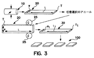
別の実施態様によれば、第2変形は、好ましくはブルームミルを用いた予備成形体スラブのブルーム圧延により達成することができる。図3は、第2変形が好ましくはブルームミル25を用いた予備成形体スラブ20のブルーム圧延により達成される本発明の1つの実施態様を示している。
According to another embodiment, the second deformation can be achieved by bloom rolling of the preform slab, preferably using a bloom mill. FIG. 3 shows one embodiment of the invention in which the second variant is preferably achieved by bloom rolling of the
本発明によるバルブ金属の多方向変形によって、約250μmよりも小さい平均粒度と(100)組織バンドの実質的にない組織とを有する中間体スラブが製造される。中間体スラブは、好ましくは約100〜約150μm、より好ましくは50μm以下の平均粒度を有する。 Multidirectional deformation of the valve metal according to the present invention produces an intermediate slab having an average particle size of less than about 250 μm and a structure substantially free of (100) tissue bands. The intermediate slab preferably has an average particle size of about 100 to about 150 [mu] m, more preferably 50 [mu] m or less.
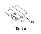
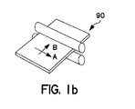
本発明によるバルブ金属の多方向変形は、例えば、図1a及び1bに示される2つ以上の方向におけるスラブの横方向圧延と対比することができる。横方向圧延プロセスにおいては、金属ワークピース90が第1方向(A)に圧延され、次いで、第1方向(A)に垂直な第2方向(B)に圧延されて、長さと幅が大きくされ、最も小さい寸法(例えば、厚さ)が小さくなるようにされる。したがって、横方向圧延は、本発明の多方向変形プロセスによってもたらされる金属90のミクロ構造に対する実質的な変化を生じさせることなく、金属ワークピースを所望の厚さに平坦化するという効果を有する。本発明によるバルブ金属の多方向変形はまた、例えば、米国特許出願公開第2002/0112789号明細書において示される金属ワークピースを先の形状に復元又は実質的に復元する冗長性鍛造(redundant forging)とは異なる。
The multi-directional deformation of the valve metal according to the invention can be contrasted with, for example, the lateral rolling of the slab in two or more directions as shown in FIGS. 1a and 1b. In the transverse rolling process, the
本発明の1つの実施態様は、中間体スラブを分割して、プレートに又はスパッタターゲットを形成するのに好適な他の形状にさらに熱機械加工することができる複数の圧延スラブを形成することをさらに伴う。分割は、中間体スラブを所定の数の所定の形状の圧延スラブに分離することにより達成することができる。分割は、例えば、切断、機械加工、ウォータージェット切断、パンチプレス、プラズマ切断、炎切断、ミリング、粉砕、のこ引き、レーザー切断、ボーリング、電極放電加工、又はそれらの任意の組み合わせによって行うことができる。1つ又は複数の圧延スラブは、特に試験又は品質管理試料として使用するためにサイズ設定することができる。圧延スラブは、方位像顕微鏡(OIM)又は他の好適な技術によって測定されるように、厚さ全体を実質的に通じて約250〜約100μm、好ましくは約150〜約100μm、より好ましくは50μm以下の平均粒度を有することができる。 One embodiment of the present invention is to divide the intermediate slab to form a plurality of rolled slabs that can be further thermo-machined into plates or other shapes suitable for forming sputter targets. Further accompanying. The division can be achieved by separating the intermediate slab into a predetermined number of predetermined shaped rolled slabs. The division may be performed, for example, by cutting, machining, water jet cutting, punch press, plasma cutting, flame cutting, milling, grinding, sawing, laser cutting, boring, electrode discharge machining, or any combination thereof. it can. One or more rolled slabs can be sized specifically for use as a test or quality control sample. The rolled slab is about 250 to about 100 [mu] m, preferably about 150 to about 100 [mu] m, more preferably 50 [mu] m substantially throughout its thickness as measured by an orientation image microscope (OIM) or other suitable technique. It can have the following average particle size:
本発明の1つの実施態様は、予備成形体スラブをアニーリングして少なくとも部分的な再結晶化を達成する更なる工程を含む。アニーリングは、5×10⁻⁴torr以上の真空において、予備成形体スラブを確実に回復させるか又はその再結晶化を完了するのに十分な温度及び時間で達成されることが好ましい。アニーリング温度は、他の温度を使用することもできるが、約950〜約1300℃が好ましい。アニーリング時間は、他のアニーリング時間を使用することもできるが、約1〜約8時間が好ましい。好ましくは、予備成形体スラブは、約1050℃の温度で約2時間アニーリングされる。任意選択で、予備成形体スラブをアニーリングする代わりに又はそれに加えて、中間体スラブをアニーリングすることができる。中間体スラブのアニーリングは、予備成形体スラブに関して記載されたのと実質的に同様に達成することができる。 One embodiment of the present invention includes the further step of annealing the preform slab to achieve at least partial recrystallization. Annealing is preferably accomplished at a temperature and time sufficient to reliably recover the preform slab or complete its recrystallization in a vacuum of 5 × 10 −4 torr or higher. The annealing temperature is preferably about 950 to about 1300 ° C., although other temperatures can be used. The annealing time can be from about 1 to about 8 hours, although other annealing times can be used. Preferably, the preform slab is annealed at a temperature of about 1050 ° C. for about 2 hours. Optionally, instead of or in addition to annealing the preform slab, the intermediate slab can be annealed. Annealing of the intermediate slab can be accomplished in substantially the same manner as described for the preform slab.
本発明の1つの実施態様によれば、予備成形体スラブの第2変形工程は、予備成形体を実質的にロッドの形状に形成し、さらに当該ロッドを分割して複数のビレットを形成することを含む。ロッドの分割は、上記のような任意の方法によって行うことができる。ビレットは、プレートに又はディスク、円筒若しくは種々の他の形状の他のターゲットを形成するのに好適な他のミル成形体にさらに熱機械加工するのに好適な任意の所定の長さであることができる。図4は、ロッド40を得るためのバルブ金属、例えば、タンタル又はニオブインゴットの多方向変形の1つの実施態様を示している。次に、ロッドは、米国特許第6,348,113号明細書(Michalukら)に従って、加工するのに好適なビレット50に切断することができる。任意選択で、ロッドはビレットへの切断の前にアニーリングすることができる。
According to one embodiment of the present invention, the second deformation step of the preform slab includes forming the preform substantially in the shape of a rod, and further dividing the rod to form a plurality of billets. including. The rod can be divided by any method as described above. The billet is of any predetermined length suitable for further thermo-machining on a plate or other mill compact suitable for forming a disk, cylinder or other target of various other shapes Can do. FIG. 4 shows one embodiment of the multi-directional deformation of the valve metal, such as tantalum or niobium ingot, to obtain the
本発明の1つの実施態様は、第1寸法に対して直角に予備成形体スラブを分割して複数の中間体スラブを形成することを伴う。結果として、個々の中間体スラブは、予備成形体スラブの第1寸法よりも小さい第1寸法と、中間体スラブの第1寸法に垂直な第2寸法と、中間体スラブの第2寸法に垂直で予備成形体スラブの第1寸法及び第2寸法よりも小さい第3寸法とを有する。本方法は、中間体スラブの第1寸法を第3寸法よりも小さくし、それにより圧延スラブを形成するように、中間体スラブの第3寸法を大きくしかつ第1寸法を小さくすることによる中間体スラブの少なくとも1つの第2変形をさらに含む。第1及び第2変形工程は、インゴットの多方向変形に相当する。好ましくは、圧延スラブは、約100μm以下若しくは約50μm以下の平均粒度、及び/又は組織バンド、例えば、(100)組織バンドの実質的にない組織を有する。組織は、一次(111)若しくは一次(100)組織又は混合(111)(100)組織であることができ、これら組織のすべては、好ましくは表面上で及び/又は厚さを通して均一である。任意選択で、予備成形体スラブ、中間体スラブ又はその両方は、1回又は複数回アニーリングすることができる。 One embodiment of the invention involves dividing the preform slab to form a plurality of intermediate slabs at right angles to the first dimension. As a result, each intermediate slab has a first dimension that is smaller than the first dimension of the preform slab, a second dimension that is perpendicular to the first dimension of the intermediate slab, and a second dimension that is perpendicular to the second dimension of the intermediate slab. And a third dimension smaller than the first dimension and the second dimension of the preform slab. The method includes intermediate by increasing the third dimension of the intermediate slab and decreasing the first dimension so that the first dimension of the intermediate slab is smaller than the third dimension, thereby forming a rolled slab. Further comprising at least one second deformation of the body slab. The first and second deformation steps correspond to multidirectional deformation of the ingot. Preferably, the rolled slab has an average particle size of about 100 μm or less or about 50 μm or less, and / or a texture band substantially free of texture bands, eg, (100) texture bands. The tissue can be primary (111) or primary (100) tissue or mixed (111) (100) tissue, all of which are preferably uniform on the surface and / or throughout the thickness. Optionally, the preform slab, the intermediate slab, or both can be annealed once or multiple times.
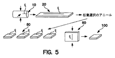
図5は、第1寸法に対して直角に予備成形体スラブ20を分割することで、複数の中間体スラブ60が形成される本発明の実施態様を示している。結果として、個々の中間体スラブ60は、予備成形体スラブ20の第1寸法よりも小さい第1寸法と、中間体スラブ20の第1寸法に垂直な第2寸法と、中間体スラブ20の第2寸法に垂直で予備成形体スラブ20の第1寸法及び第2寸法よりも小さい第3寸法とを有する。本方法は、中間体スラブ20の第1寸法を第3寸法よりも小さくし、それにより圧延スラブ100を形成するように、中間体スラブ20の第3寸法を大きくしかつ第1寸法を小さくすることによる中間体スラブ20の少なくとも1つの第2変形をさらに含む。
FIG. 5 shows an embodiment of the invention in which a plurality of
本発明の他の実施態様は、本明細書を考慮し、本明細書に開示される本発明を実施することにより当業者に明らかであろう。本明細書及び例は単に例示的なものとみなされ、本発明の真の範囲及び趣旨は、特許請求の範囲及びそれと同等なものによって示されるものである。 Other embodiments of the invention will be apparent to those skilled in the art from consideration of the specification and practice of the invention disclosed herein. It is intended that the specification and examples be considered as exemplary only, with a true scope and spirit of the invention being indicated by the appended claims and equivalents thereof.
Claims (37)
第1寸法と、第1寸法に垂直な第2寸法と、第2寸法に垂直で第1及び第2寸法よりも小さい第3寸法とを有する予備成形体スラブを形成するためのインゴットの第1変形;並びに
第2寸法を第3寸法よりも小さくして約250μmよりも小さい平均粒度を有する中間体スラブを形成するように、第3寸法を大きくしかつ第2寸法を小さくすることによる当該予備成形体スラブの第2変形
を含む、方法。 A method of manufacturing a multi-directionally deformed valve metal having dimensions sufficient to divide to form a plurality of sputter targets,
A first ingot for forming a preform slab having a first dimension, a second dimension perpendicular to the first dimension, and a third dimension perpendicular to the second dimension and less than the first and second dimensions. The preliminary by increasing the third dimension and reducing the second dimension so as to form an intermediate slab having an average particle size less than about 250 μm by making the second dimension smaller than the third dimension; A method comprising a second deformation of the shaped body slab.
第1寸法と、第1寸法に垂直な第2寸法と、第2寸法に垂直で第1及び第2寸法よりも小さい第3寸法とを有する予備成形体スラブを形成するためのインゴットの第1変形;
約250μmよりも小さい平均粒度を有するロッドを形成するための当該予備成形体スラブの第2変形;並びに
複数のビレットを形成するための当該ロッドの分割
を含む、方法。 A method of manufacturing a multi-directionally deformed valve metal having dimensions sufficient to divide to form a plurality of sputter targets,
A first ingot for forming a preform slab having a first dimension, a second dimension perpendicular to the first dimension, and a third dimension perpendicular to the second dimension and less than the first and second dimensions. Deformation;
A method comprising: a second deformation of the preform slab to form a rod having an average particle size of less than about 250 μm; and splitting the rod to form a plurality of billets.
第1寸法と、第1寸法に垂直な第2寸法と、第2寸法に垂直で第1及び第2寸法よりも小さい第3寸法とを有する予備成形体スラブを形成するためのインゴットの第1変形;
当該予備成形体スラブを第1寸法に対して直角に分割して複数の中間体スラブを形成するための予備成形体スラブの分割であって、それぞれの中間体スラブが、予備成形体スラブの第1寸法よりも小さい第1寸法と、中間体スラブの第1寸法に垂直な第2寸法と、中間体スラブの第2寸法に垂直で予備成形体スラブの第1寸法及び第2寸法よりも小さい第3寸法とを有する、予備成形体スラブの分割;並びに
少なくとも1つの中間体スラブの第1寸法を、当該少なくとも1つの中間体スラブの第3寸法よりも小さくして約250μmよりも小さい平均粒度を有する圧延スラブを形成するように、少なくとも1つの中間体スラブの第3寸法を大きくしかつ少なくとも1つの中間体スラブの第1寸法を小さくすることによる中間体スラブの少なくとも1つの第2変形
を含む、方法。 A method of manufacturing a multi-directionally deformed valve metal having dimensions sufficient to divide to form a plurality of sputter targets,
A first ingot for forming a preform slab having a first dimension, a second dimension perpendicular to the first dimension, and a third dimension perpendicular to the second dimension and less than the first and second dimensions. Deformation;
The preform slab is divided at a right angle with respect to the first dimension to form a plurality of intermediate slabs, each of the intermediate slabs being the first of the preform slabs. A first dimension that is less than one dimension, a second dimension that is perpendicular to the first dimension of the intermediate slab, and a dimension that is perpendicular to the second dimension of the intermediate slab and smaller than the first dimension and the second dimension of the preform slab Splitting the preform slab having a third dimension; and an average particle size of the first dimension of the at least one intermediate slab that is less than the third dimension of the at least one intermediate slab and less than about 250 μm. Less intermediate slabs by increasing the third dimension of at least one intermediate slab and decreasing the first dimension of at least one intermediate slab so as to form a rolled slab having Also includes one of the second variant, the method.
Applications Claiming Priority (2)
| Application Number | Priority Date | Filing Date | Title |
|---|---|---|---|
| US47698403P | 2003-06-09 | 2003-06-09 | |
| PCT/US2004/017972 WO2004111295A1 (en) | 2003-06-09 | 2004-06-07 | Method of forming sputtering acticles by multidirectional deformation |
Publications (2)
| Publication Number | Publication Date |
|---|---|
| JP2007516352A true JP2007516352A (en) | 2007-06-21 |
| JP2007516352A5 JP2007516352A5 (en) | 2007-08-02 |
Family
ID=33551657
Family Applications (1)
| Application Number | Title | Priority Date | Filing Date |
|---|---|---|---|
| JP2006533580A Pending JP2007516352A (en) | 2003-06-09 | 2004-06-07 | Method for forming a sputtering article by multi-directional deformation |
Country Status (5)
| Country | Link |
|---|---|
| US (1) | US7228722B2 (en) |
| EP (1) | EP1636398A1 (en) |
| JP (1) | JP2007516352A (en) |
| CN (1) | CN1833048A (en) |
| WO (1) | WO2004111295A1 (en) |
Cited By (4)
| Publication number | Priority date | Publication date | Assignee | Title |
|---|---|---|---|---|
| JP2008532765A (en) * | 2005-02-10 | 2008-08-21 | キャボット コーポレイション | Sputtering target and manufacturing method thereof |
| JP2010535633A (en) * | 2007-08-06 | 2010-11-25 | エイチ.シー. スターク インコーポレイテッド | Method of controlling the structure of plates and sheets by tilt rolling |
| KR101193868B1 (en) | 2010-07-29 | 2012-10-26 | 현대제철 주식회사 | Method for roughing mill of taper slab |
| CN108356193A (en) * | 2018-05-22 | 2018-08-03 | 通裕重工股份有限公司 | Rotor of steam turbo generator free forging method |
Families Citing this family (10)
| Publication number | Priority date | Publication date | Assignee | Title |
|---|---|---|---|---|
| KR101466996B1 (en) | 2006-03-07 | 2014-12-01 | 캐보트 코포레이션 | Methods of producing deformed metal articles |
| US20070251819A1 (en) * | 2006-05-01 | 2007-11-01 | Kardokus Janine K | Hollow cathode magnetron sputtering targets and methods of forming hollow cathode magnetron sputtering targets |
| US7776166B2 (en) * | 2006-12-05 | 2010-08-17 | Praxair Technology, Inc. | Texture and grain size controlled hollow cathode magnetron targets and method of manufacture |
| KR100860645B1 (en) * | 2007-05-04 | 2008-09-26 | 엘지전자 주식회사 | Refrigerator and steel plate of door for refrigerator and manufacturing method thereof |
| US8250895B2 (en) * | 2007-08-06 | 2012-08-28 | H.C. Starck Inc. | Methods and apparatus for controlling texture of plates and sheets by tilt rolling |
| US8702919B2 (en) * | 2007-08-13 | 2014-04-22 | Honeywell International Inc. | Target designs and related methods for coupled target assemblies, methods of production and uses thereof |
| KR101626286B1 (en) * | 2008-11-03 | 2016-06-01 | 토소우 에스엠디, 인크 | Method of making a sputter target and sputter targets made thereby |
| US20100180427A1 (en) * | 2009-01-16 | 2010-07-22 | Ford Motor Company | Texturing of thin metal sheets/foils for enhanced formability and manufacturability |
| US20100330389A1 (en) * | 2009-06-25 | 2010-12-30 | Ford Motor Company | Skin pass for cladding thin metal sheets |
| CN107466328A (en) | 2015-04-10 | 2017-12-12 | 东曹Smd有限公司 | The manufacture method of tantalum spattering target and the sputtering target being made from it |
Citations (4)
| Publication number | Priority date | Publication date | Assignee | Title |
|---|---|---|---|---|
| US6193821B1 (en) * | 1998-08-19 | 2001-02-27 | Tosoh Smd, Inc. | Fine grain tantalum sputtering target and fabrication process |
| JP2002530534A (en) * | 1998-11-25 | 2002-09-17 | キャボット コーポレイション | High purity tantalum and products containing it, such as sputter targets |
| JP2004511651A (en) * | 2000-05-22 | 2004-04-15 | キャボット コーポレイション | High purity niobium, product containing the same, and method for producing the same |
| JP2004526863A (en) * | 2001-02-20 | 2004-09-02 | ハー ツェー シュタルク インコーポレイテッド | Refractory metal plate having uniform texture and method for producing the plate |
Family Cites Families (15)
| Publication number | Priority date | Publication date | Assignee | Title |
|---|---|---|---|---|
| US4721537A (en) * | 1985-10-15 | 1988-01-26 | Rockwell International Corporation | Method of producing a fine grain aluminum alloy using three axes deformation |
| DE3712281A1 (en) * | 1987-04-10 | 1988-10-27 | Heraeus Gmbh W C | METHOD FOR PRODUCING HIGHLY DUCTILE TANTALE SEMI-FINISHED PRODUCTS |
| FR2729596A1 (en) * | 1992-05-07 | 1996-07-26 | Commissariat Energie Atomique | PROCESS FOR PRODUCING METALLIC PARTS BY FREE FORGING AND PRESSING MATRIX |
| US5390518A (en) * | 1992-11-10 | 1995-02-21 | Mitsubishi Jukogyo Kabushiki Kaisha | Method for shining metal sheet surfaces and method for cold-rolling metallic materials |
| US5647923A (en) * | 1995-07-13 | 1997-07-15 | Teledyne Industries, Inc. | Method for producing refractory metal foil |
| US5993513A (en) * | 1996-04-05 | 1999-11-30 | Cabot Corporation | Method for controlling the oxygen content in valve metal materials |
| US6569270B2 (en) * | 1997-07-11 | 2003-05-27 | Honeywell International Inc. | Process for producing a metal article |
| US6348139B1 (en) * | 1998-06-17 | 2002-02-19 | Honeywell International Inc. | Tantalum-comprising articles |
| US6331233B1 (en) * | 2000-02-02 | 2001-12-18 | Honeywell International Inc. | Tantalum sputtering target with fine grains and uniform texture and method of manufacture |
| US20020002695A1 (en) | 2000-06-02 | 2002-01-03 | Frank Kschischang | Method and system for decoding |
| US6946039B1 (en) * | 2000-11-02 | 2005-09-20 | Honeywell International Inc. | Physical vapor deposition targets, and methods of fabricating metallic materials |
| US6887356B2 (en) * | 2000-11-27 | 2005-05-03 | Cabot Corporation | Hollow cathode target and methods of making same |
| IL156802A0 (en) | 2001-01-11 | 2004-02-08 | Cabot Corp | Tantalum and niobium billets and methods of producing same |
| US6770154B2 (en) * | 2001-09-18 | 2004-08-03 | Praxair S.T. Technology, Inc. | Textured-grain-powder metallurgy tantalum sputter target |
| US20040016635A1 (en) * | 2002-07-19 | 2004-01-29 | Ford Robert B. | Monolithic sputtering target assembly |
-
2004
- 2004-06-02 US US10/859,456 patent/US7228722B2/en active Active
- 2004-06-07 CN CNA2004800228031A patent/CN1833048A/en active Pending
- 2004-06-07 EP EP04754543A patent/EP1636398A1/en not_active Withdrawn
- 2004-06-07 WO PCT/US2004/017972 patent/WO2004111295A1/en active Application Filing
- 2004-06-07 JP JP2006533580A patent/JP2007516352A/en active Pending
Patent Citations (4)
| Publication number | Priority date | Publication date | Assignee | Title |
|---|---|---|---|---|
| US6193821B1 (en) * | 1998-08-19 | 2001-02-27 | Tosoh Smd, Inc. | Fine grain tantalum sputtering target and fabrication process |
| JP2002530534A (en) * | 1998-11-25 | 2002-09-17 | キャボット コーポレイション | High purity tantalum and products containing it, such as sputter targets |
| JP2004511651A (en) * | 2000-05-22 | 2004-04-15 | キャボット コーポレイション | High purity niobium, product containing the same, and method for producing the same |
| JP2004526863A (en) * | 2001-02-20 | 2004-09-02 | ハー ツェー シュタルク インコーポレイテッド | Refractory metal plate having uniform texture and method for producing the plate |
Cited By (11)
| Publication number | Priority date | Publication date | Assignee | Title |
|---|---|---|---|---|
| JP2008532765A (en) * | 2005-02-10 | 2008-08-21 | キャボット コーポレイション | Sputtering target and manufacturing method thereof |
| JP4880620B2 (en) * | 2005-02-10 | 2012-02-22 | キャボット コーポレイション | Sputtering target and manufacturing method thereof |
| JP2010535633A (en) * | 2007-08-06 | 2010-11-25 | エイチ.シー. スターク インコーポレイテッド | Method of controlling the structure of plates and sheets by tilt rolling |
| JP2010535943A (en) * | 2007-08-06 | 2010-11-25 | エイチ.シー. スターク インコーポレイテッド | Refractory metal plate with improved tissue uniformity |
| JP2013154403A (en) * | 2007-08-06 | 2013-08-15 | Hc Starck Inc | Method for controlling texture of plate and sheet by tilt rolling method |
| JP2014012893A (en) * | 2007-08-06 | 2014-01-23 | Hc Starck Inc | High melting metal plate with improved uniformity of texture |
| US9095885B2 (en) | 2007-08-06 | 2015-08-04 | H.C. Starck Inc. | Refractory metal plates with improved uniformity of texture |
| US9767999B2 (en) | 2007-08-06 | 2017-09-19 | H.C. Starck Inc. | Refractory metal plates |
| KR101193868B1 (en) | 2010-07-29 | 2012-10-26 | 현대제철 주식회사 | Method for roughing mill of taper slab |
| CN108356193A (en) * | 2018-05-22 | 2018-08-03 | 通裕重工股份有限公司 | Rotor of steam turbo generator free forging method |
| CN108356193B (en) * | 2018-05-22 | 2020-06-23 | 通裕重工股份有限公司 | Free forging forming method for turbonator rotor |
Also Published As
| Publication number | Publication date |
|---|---|
| WO2004111295A1 (en) | 2004-12-23 |
| EP1636398A1 (en) | 2006-03-22 |
| CN1833048A (en) | 2006-09-13 |
| US20050034503A1 (en) | 2005-02-17 |
| US7228722B2 (en) | 2007-06-12 |
Similar Documents
| Publication | Publication Date | Title |
|---|---|---|
| JP5114812B2 (en) | Method for producing deformed metal member | |
| TW515848B (en) | Tantalum sputtering target and process of making same | |
| JP4880620B2 (en) | Sputtering target and manufacturing method thereof | |
| CN100334252C (en) | Tantalum sputtering target and method for preparation thereof | |
| KR101201577B1 (en) | Refractory metal plates with improved uniformity of texture | |
| KR101626286B1 (en) | Method of making a sputter target and sputter targets made thereby | |
| US20030052000A1 (en) | Fine grain size material, sputtering target, methods of forming, and micro-arc reduction method | |
| JP2007516352A (en) | Method for forming a sputtering article by multi-directional deformation | |
| EP1027463A1 (en) | Metal article with fine uniform structures and textures and process of making same | |
| JP2004526863A (en) | Refractory metal plate having uniform texture and method for producing the plate | |
| KR20210047343A (en) | Sputtering target and its manufacturing method | |
| KR20210053940A (en) | Sputtering target and its manufacturing method | |
| JP3073734B1 (en) | Method of manufacturing Fe-Ni alloy material for shadow mask |
Legal Events
| Date | Code | Title | Description |
|---|---|---|---|
| A521 | Written amendment |
Free format text: JAPANESE INTERMEDIATE CODE: A523 Effective date: 20070607 |
|
| A621 | Written request for application examination |
Free format text: JAPANESE INTERMEDIATE CODE: A621 Effective date: 20070607 |
|
| A131 | Notification of reasons for refusal |
Free format text: JAPANESE INTERMEDIATE CODE: A131 Effective date: 20101012 |
|
| A601 | Written request for extension of time |
Free format text: JAPANESE INTERMEDIATE CODE: A601 Effective date: 20110111 |
|
| A602 | Written permission of extension of time |
Free format text: JAPANESE INTERMEDIATE CODE: A602 Effective date: 20110118 |
|
| A521 | Written amendment |
Free format text: JAPANESE INTERMEDIATE CODE: A523 Effective date: 20110412 |
|
| A02 | Decision of refusal |
Free format text: JAPANESE INTERMEDIATE CODE: A02 Effective date: 20110816 Free format text: JAPANESE INTERMEDIATE CODE: A02 Effective date: 20110816 |