JP2007515282A - Feeding device for UV lamp used for water treatment - Google Patents
Feeding device for UV lamp used for water treatment Download PDFInfo
- Publication number
- JP2007515282A JP2007515282A JP2006546224A JP2006546224A JP2007515282A JP 2007515282 A JP2007515282 A JP 2007515282A JP 2006546224 A JP2006546224 A JP 2006546224A JP 2006546224 A JP2006546224 A JP 2006546224A JP 2007515282 A JP2007515282 A JP 2007515282A
- Authority
- JP
- Japan
- Prior art keywords
- lamp
- lamps
- ballast
- warm
- power supply
- Prior art date
- Legal status (The legal status is an assumption and is not a legal conclusion. Google has not performed a legal analysis and makes no representation as to the accuracy of the status listed.)
- Pending
Links
- XLYOFNOQVPJJNP-UHFFFAOYSA-N water Substances O XLYOFNOQVPJJNP-UHFFFAOYSA-N 0.000 title claims abstract description 22
- 230000001954 sterilising effect Effects 0.000 claims abstract description 6
- 239000003990 capacitor Substances 0.000 claims description 6
- 238000004659 sterilization and disinfection Methods 0.000 claims description 6
- QSHDDOUJBYECFT-UHFFFAOYSA-N mercury Chemical compound [Hg] QSHDDOUJBYECFT-UHFFFAOYSA-N 0.000 claims description 2
- 239000004020 conductor Substances 0.000 description 10
- 238000010792 warming Methods 0.000 description 6
- 238000000034 method Methods 0.000 description 5
- 238000009434 installation Methods 0.000 description 4
- 230000003071 parasitic effect Effects 0.000 description 3
- 238000010586 diagram Methods 0.000 description 2
- 239000003651 drinking water Substances 0.000 description 2
- 235000020188 drinking water Nutrition 0.000 description 2
- 230000000694 effects Effects 0.000 description 2
- 238000009281 ultraviolet germicidal irradiation Methods 0.000 description 2
- 241000894006 Bacteria Species 0.000 description 1
- 241000700605 Viruses Species 0.000 description 1
- 235000013361 beverage Nutrition 0.000 description 1
- 238000006243 chemical reaction Methods 0.000 description 1
- 239000013626 chemical specie Substances 0.000 description 1
- 238000006298 dechlorination reaction Methods 0.000 description 1
- 238000005286 illumination Methods 0.000 description 1
- 238000004519 manufacturing process Methods 0.000 description 1
- 244000005700 microbiome Species 0.000 description 1
- 238000000746 purification Methods 0.000 description 1
- 239000010453 quartz Substances 0.000 description 1
- 230000001105 regulatory effect Effects 0.000 description 1
- 239000011347 resin Substances 0.000 description 1
- 229920005989 resin Polymers 0.000 description 1
- VYPSYNLAJGMNEJ-UHFFFAOYSA-N silicon dioxide Inorganic materials O=[Si]=O VYPSYNLAJGMNEJ-UHFFFAOYSA-N 0.000 description 1
- 241000894007 species Species 0.000 description 1
- 229910001220 stainless steel Inorganic materials 0.000 description 1
- 239000010935 stainless steel Substances 0.000 description 1
Images


Classifications
-
- C—CHEMISTRY; METALLURGY
- C02—TREATMENT OF WATER, WASTE WATER, SEWAGE, OR SLUDGE
- C02F—TREATMENT OF WATER, WASTE WATER, SEWAGE, OR SLUDGE
- C02F1/00—Treatment of water, waste water, or sewage
- C02F1/30—Treatment of water, waste water, or sewage by irradiation
- C02F1/32—Treatment of water, waste water, or sewage by irradiation with ultraviolet light
-
- H—ELECTRICITY
- H05—ELECTRIC TECHNIQUES NOT OTHERWISE PROVIDED FOR
- H05B—ELECTRIC HEATING; ELECTRIC LIGHT SOURCES NOT OTHERWISE PROVIDED FOR; CIRCUIT ARRANGEMENTS FOR ELECTRIC LIGHT SOURCES, IN GENERAL
- H05B41/00—Circuit arrangements or apparatus for igniting or operating discharge lamps
- H05B41/02—Details
-
- C—CHEMISTRY; METALLURGY
- C02—TREATMENT OF WATER, WASTE WATER, SEWAGE, OR SLUDGE
- C02F—TREATMENT OF WATER, WASTE WATER, SEWAGE, OR SLUDGE
- C02F1/00—Treatment of water, waste water, or sewage
- C02F1/30—Treatment of water, waste water, or sewage by irradiation
- C02F1/32—Treatment of water, waste water, or sewage by irradiation with ultraviolet light
- C02F1/325—Irradiation devices or lamp constructions
-
- H—ELECTRICITY
- H05—ELECTRIC TECHNIQUES NOT OTHERWISE PROVIDED FOR
- H05B—ELECTRIC HEATING; ELECTRIC LIGHT SOURCES NOT OTHERWISE PROVIDED FOR; CIRCUIT ARRANGEMENTS FOR ELECTRIC LIGHT SOURCES, IN GENERAL
- H05B41/00—Circuit arrangements or apparatus for igniting or operating discharge lamps
- H05B41/14—Circuit arrangements
- H05B41/26—Circuit arrangements in which the lamp is fed by power derived from dc by means of a converter, e.g. by high-voltage dc
- H05B41/28—Circuit arrangements in which the lamp is fed by power derived from dc by means of a converter, e.g. by high-voltage dc using static converters
- H05B41/282—Circuit arrangements in which the lamp is fed by power derived from dc by means of a converter, e.g. by high-voltage dc using static converters with semiconductor devices
- H05B41/2821—Circuit arrangements in which the lamp is fed by power derived from dc by means of a converter, e.g. by high-voltage dc using static converters with semiconductor devices by means of a single-switch converter or a parallel push-pull converter in the final stage
- H05B41/2822—Circuit arrangements in which the lamp is fed by power derived from dc by means of a converter, e.g. by high-voltage dc using static converters with semiconductor devices by means of a single-switch converter or a parallel push-pull converter in the final stage using specially adapted components in the load circuit, e.g. feed-back transformers, piezoelectric transformers; using specially adapted load circuit configurations
-
- H—ELECTRICITY
- H05—ELECTRIC TECHNIQUES NOT OTHERWISE PROVIDED FOR
- H05B—ELECTRIC HEATING; ELECTRIC LIGHT SOURCES NOT OTHERWISE PROVIDED FOR; CIRCUIT ARRANGEMENTS FOR ELECTRIC LIGHT SOURCES, IN GENERAL
- H05B41/00—Circuit arrangements or apparatus for igniting or operating discharge lamps
- H05B41/14—Circuit arrangements
- H05B41/36—Controlling
-
- C—CHEMISTRY; METALLURGY
- C02—TREATMENT OF WATER, WASTE WATER, SEWAGE, OR SLUDGE
- C02F—TREATMENT OF WATER, WASTE WATER, SEWAGE, OR SLUDGE
- C02F2201/00—Apparatus for treatment of water, waste water or sewage
- C02F2201/32—Details relating to UV-irradiation devices
- C02F2201/322—Lamp arrangement
- C02F2201/3227—Units with two or more lamps
-
- C—CHEMISTRY; METALLURGY
- C02—TREATMENT OF WATER, WASTE WATER, SEWAGE, OR SLUDGE
- C02F—TREATMENT OF WATER, WASTE WATER, SEWAGE, OR SLUDGE
- C02F2201/00—Apparatus for treatment of water, waste water or sewage
- C02F2201/32—Details relating to UV-irradiation devices
- C02F2201/326—Lamp control systems
Abstract
本発明は、紫外線により水を殺菌する装置に関する。この装置は、少なくとも2つの放電ランプ(2、3)を含み、これらのランプ(2、3)はこれらを予加熱し、点灯するための手段及びランプの正常動作を保証する手段を含む供給手段に電線(5a、5b)により接続されている。本発明では、予加熱手段の電気部品(4a、4b)の少なくとも1つが、前記ランプのごく近傍に設けられ、前記供給手段の他の部品が、それらから少し離れて設けられていることを特徴とする。
The present invention relates to an apparatus for sterilizing water with ultraviolet rays. The device comprises at least two discharge lamps (2, 3), which supply means comprising means for preheating and lighting them and means for ensuring the normal operation of the lamp Are connected by electric wires (5a, 5b). In the present invention, at least one of the electrical parts (4a, 4b) of the preheating means is provided in the very vicinity of the lamp, and the other parts of the supply means are provided at a distance from them. And
Description
本発明は、精製工程及び飲料水の製造工程の両方のための水処理の分野に関する。より正確には、本発明はUVランプを使用する紫外線による水処理に関する。 The present invention relates to the field of water treatment for both the purification process and the drinking water production process. More precisely, the present invention relates to water treatment with ultraviolet light using a UV lamp.
UVランプは、水を飲料に適するようにするか又は精製するために設けられた水処理設備で通常使用されている。 UV lamps are commonly used in water treatment facilities provided to make water suitable for beverages or to be purified.
従って、そのようなランプは、飲料水プラントに組込まれた水殺菌ユニット中にしばしば使用される。微生物、例えば、ウイルス及びバクテリアは、ある波長の紫外線により誘発された光化学効果下で活性を失うか又は死滅する。 Accordingly, such lamps are often used in water sterilization units built into drinking water plants. Microorganisms such as viruses and bacteria lose activity or die under the photochemical effects induced by certain wavelengths of ultraviolet light.
これらのUVランプが施与するエネルギーは、水中に存在する塩素化種を変換することができる化学種の出現を促すので、これらのランプは脱塩素化ユニットでも使用される。 These lamps are also used in dechlorination units because the energy applied by these UV lamps encourages the emergence of chemical species that can convert chlorinated species present in the water.
通常はステンレススチールで製造され、その中を処理すべき水が循環し、ランプが完全に沈められている開放チャネル又は閉鎖反応容器中において、そのようなUVランプを使用することができる。 Such UV lamps can be used in open channels or closed reaction vessels, usually made of stainless steel, in which the water to be treated circulates and the lamp is completely submerged.
1列又は数列のランプは、通常、チャネル中に備えられており、波長200nm〜300nm、通常は254nm、の紫外線を施与する。これらの列は、しばしば相互に平行であるモジュールに組み立てることができる。各モジュールは、石英ジャケットにより保護されたUVランプ1列又は数列から構成される。 One or several rows of lamps are usually provided in the channel and apply UV light with a wavelength of 200 nm to 300 nm, usually 254 nm. These rows can often be assembled into modules that are parallel to each other. Each module consists of one or several rows of UV lamps protected by a quartz jacket.
水処理に使用されるUVランプは、電気ケーブルを介して電力供給手段に接続され、この電力供給手段は、ランプのウォーミングアップ及び点火手段と、ランプの正常なUV照射を保証する手段とを含む。 The UV lamp used for water treatment is connected to power supply means via an electrical cable, which power supply means includes means for warming up and igniting the lamp and means for ensuring normal UV irradiation of the lamp.
当業者は、これらの電力供給手段を「バラスト」と呼ぶ。バラストは、本来、完全に受動的であり、電源電圧の低周波数を周波数20〜80kHzまで上げるエレクトロニックコンバーターからなる。エレクトロニックバラストは、ランプに供給される電力の調整を含む種々の目的のために使用できる。 Those skilled in the art refer to these power supply means as “ballasts”. Ballasts are inherently passive and consist of an electronic converter that raises the low frequency of the supply voltage to a frequency of 20-80 kHz. Electronic ballasts can be used for a variety of purposes including regulating the power supplied to the lamp.
このバラストは、ランプ自体から少し離れて設置され、電気ケーブルによりランプに接続される。 This ballast is installed at a distance from the lamp itself and is connected to the lamp by an electrical cable.
そのような装置を水処理のために使用する場合、ランプのバラストは、例えば樹脂を使用して、漏れないか又は漏れないようにされた電気キャビネット中の水の外に設置されねばならない。 When such a device is used for water treatment, the lamp ballast must be installed out of the water in an electrical cabinet that is or does not leak, eg using resin.
従って、ランプをバラストに接続する各ケーブルは長い。 Thus, each cable connecting the lamp to the ballast is long.
各UVランプは、4本の電線によりバラストに接続されて、以下のことに独立して対処することができる。ランプのウォーミングアップ段階と、通常照射モードの間の動作段階とである。 Each UV lamp is connected to the ballast by four wires and can independently handle: A lamp warm-up phase and an operational phase during normal illumination mode.
ウォーミングアップ段階の間、電極を通過する電流量は、その中に含まれるプラズマのイオン化を惹き起こさない。このウォーミングアップ段階の後、ランプの点火が行なわれ、その間、電圧のピークがランプに送られて、レゾナンスピークを経るバラストの周波数の変動に起因して、最初のイオン化が実現する。次いで、ランプは通常のUV照射モードで動作し、このモードでは、4つのコネクションが1つの電極から他の電極へとプラズマ中を通過する電流量を、発電機の周波数の関数として対処し、このことが、ランプによるUV光子の放出を惹き起こす。 During the warm-up phase, the amount of current passing through the electrode does not cause ionization of the plasma contained therein. After this warm-up phase, the lamp is ignited, during which time a voltage peak is sent to the lamp, and the initial ionization is achieved due to the variation in ballast frequency through the resonance peak. The lamp then operates in the normal UV irradiation mode, in which the four connections deal with the amount of current passing through the plasma from one electrode to the other as a function of the generator frequency, and this This causes the emission of UV photons by the lamp.
一部の製造業者は、製品の競争力を増すために、1個のバラストから2つのUVランプへ電力を供給することを思いついた。この応用が経済的に魅力的でありうる以前に、これらのランプは、直列で又は部分的に直列で設置されねばならない。2つのランプを並列で設置することは、電気部品の数を増加させ、かつ実際には、単一のバラストで、電子カード上に2つのバラストを製造することと等価である。2つのランプを直列に設置すると、その端末へ適用される電圧を、単に、2倍に増やすことにより、単一のUVランプに電力を供給するのに使用されるバラストを構成する電気部品を大きく変更せずに、直列に設置された2つのランプの電源を可能にする。この単純化は、それに相当する節約をもたらす。 Some manufacturers have come up with power from one ballast to two UV lamps to increase product competitiveness. Before this application can be economically attractive, these lamps must be installed in series or partially in series. Installing two lamps in parallel increases the number of electrical components and is actually equivalent to producing two ballasts on an electronic card with a single ballast. When two lamps are installed in series, the electrical components that make up the ballast used to power a single UV lamp are increased by simply doubling the voltage applied to the terminal. Without change, allows the power supply of two lamps installed in series. This simplification results in a corresponding saving.
しかしながら、直列の幾つかのUVランプのための現存の電力供給システムは、ランプ1つにつき4本の導線をまだ使用する。ランプが直列で接続されている場合ですら、種々のサイクルをうまくマネージメントできるために、ウォーミングアップの電流及びアーク電流を制御する必要性があり、そのことにより、6〜8本の線で、バラストと直列の2つのランプとの間を配線することが強いられる。電磁シールディング手段が、これらの導線に取り付けられる。 However, existing power supply systems for several UV lamps in series still use 4 wires per lamp. Even when the lamps are connected in series, there is a need to control the warm-up current and the arc current in order to be able to manage the various cycles well, so that with 6-8 wires, the ballast and It is forced to wire between two lamps in series. Electromagnetic shielding means are attached to these conductors.
従来技術によるこの技法の1つの欠点は、バラストあたり6〜8本の導線を使用し、シールディングを取り付けるので、コストが比較的高いことである。 One drawback of this technique according to the prior art is that it uses 6-8 conductors per ballast and has a relatively high cost because it is fitted with shielding.
従来技術によるこの技法の他の欠点は、バラストとランプとの間の接続距離が最大15mに限定されることである。バラストとランプとの間の接続距離が増加すると、ケーブルのインピーダンスは、共振バラスト電力供給回路のインピーダンスに比較して、もはや無視できず、これは、ランプが正しく動作するのを妨げる。更に、導線の長さに比例する導線間の寄生容量(parasite capacitance)は、その際、バラストの正しい動作に影響し、ランプ電力供給に非対称を生じる。 Another disadvantage of this technique according to the prior art is that the connection distance between the ballast and the lamp is limited to a maximum of 15 m. As the connection distance between the ballast and the lamp increases, the impedance of the cable is no longer negligible compared to the impedance of the resonant ballast power supply circuit, which prevents the lamp from operating correctly. Furthermore, the parasitic capacitance, which is proportional to the length of the conductors, then affects the correct operation of the ballast and causes an asymmetry in the lamp power supply.
水処理のためにUVランプを使用する装置に関するこの技術の他の欠点は、バラストが水に近接する場合、バラストを水から保護する必要があることから生じる。ランプの配線長さを減じることは、必然的にバラストをランプ、従って水に近接させることになり、そのため、バラスト又はバラストを含む電気キャビネットもしくはボックスのどちらかを漏れ止めにする必要がある。他の結果は、使用が難しく、コストを上げる。 Another disadvantage of this technique for devices that use UV lamps for water treatment arises from the need to protect the ballast from water when the ballast is in close proximity to the water. Reducing the lamp wiring length inevitably causes the ballast to be in close proximity to the lamp and thus the water, so either the ballast or the electrical cabinet or box containing the ballast needs to be leakproof. Other results are difficult to use and increase costs.
従来技術によるこの技法のもう1つの欠点は、長い導線を使用することに付随し、本質的にその無視できないインピーダンスによる、エネルギーの損失である。 Another disadvantage of this technique according to the prior art is the loss of energy associated with the use of long conductors and essentially due to its non-negligible impedance.
特に、本発明の目的は、従来技術によるこれらの欠点を克服するための装置を提案することである。 In particular, the object of the present invention is to propose an apparatus for overcoming these drawbacks according to the prior art.
本発明の1つの目的は、実行するのに安価であるシンプルな装置を提案することである。 One object of the present invention is to propose a simple device that is inexpensive to implement.
本発明の別の目的は、特に、ランプをウォーミングアップする場合に、ランプの「対照的」動作を促進する装置を提案することである。 Another object of the present invention is to propose a device that facilitates the “contrasting” operation of the lamp, particularly when warming up the lamp.
本発明のもう1つの目的は、その動作を変えずに、バラストとUVランプとの間の接続ケーブルの長さを増加させる装置を提供することである。 Another object of the present invention is to provide an apparatus that increases the length of the connecting cable between the ballast and the UV lamp without changing its operation.
本発明のもう1つの目的は、より良い広範囲な電気効率で、単一のバラストを備えたUVランプ少なくとも2つ用の電力供給源を使用する、紫外線による水殺菌装置を提供することである。 Another object of the present invention is to provide an ultraviolet water disinfection device that uses a power supply for at least two UV lamps with a single ballast, with better and wider electrical efficiency.
後に明白となるこれら及び他の利点は、放電ランプを少なくとも2つ含み、前記ランプが、ランプのウォーミングアップ及び点火手段と、ランプの正常動作を達成する手段とを含む電力供給手段に電線で接続された、紫外線による水殺菌装置を使用することで得られ、前記ウォーミングアップ手段の電気部品の少なくとも1つが、前記ランプのごく近傍に設けられ、前記電力供給手段の他の部品が、それらから少し離れて設けられていることを特徴とする。 These and other advantages that will become apparent later include at least two discharge lamps, which are connected by electrical wires to power supply means including lamp warm-up and ignition means and means for achieving normal operation of the lamp. In addition, it is obtained by using a water sterilization apparatus using ultraviolet rays, and at least one of the electric parts of the warming-up means is provided in the immediate vicinity of the lamp, and the other parts of the power supply means are slightly separated from them It is provided.
本発明により、前記ランプのウォーミングアップに関与する電気部品の少なくとも1つは、ランプの近くに位置する。 According to the invention, at least one of the electrical components involved in the warming up of the lamp is located near the lamp.
従って、本発明は、ウォーミングアップに関与する電力供給手段の部品の幾つかをランプ近くに配置し、かつ電力供給手段の他の部品をこれらのランプから少し離して配置することからなる新規及び発明的アプローチに基づく。 Accordingly, the present invention is a novel and inventive method comprising placing some of the parts of the power supply means involved in warming up near the lamps and placing other parts of the power supply means a little away from these lamps. Based on approach.
技術水準では、これらの部品は、ランプから離れて、バラスト内に完全に一体化されている。 In the state of the art, these parts are completely integrated in the ballast, away from the lamp.
そのような配置は、バラストとランプとの間の導線数を2本のみ迄減じることができ、そうして、バラスト又はバラストを含む電気キャビネットを漏れ止めにする必要性なしで、等価の長さのための配線のインピーダンスを減じる。また、寄生容量に起因するランプ電力供給非対称を減じる。結果として、従来可能であったよりも著しく長いケーブル長さが可能である(30mまで)。この配置により、装置を低コストで使用でき、より良い電気効率を得ることができる。 Such an arrangement can reduce the number of conductors between the ballast and the lamp to only two, and thus an equivalent length without the need to make the ballast or the electrical cabinet containing the ballast leak-proof. Reduce wiring impedance for. It also reduces lamp power supply asymmetry due to parasitic capacitance. As a result, cable lengths that are significantly longer than previously possible are possible (up to 30 m). With this arrangement, the device can be used at low cost, and better electrical efficiency can be obtained.
本発明の範囲内において、「ごく近傍に」という表現は、0.5m未満の距離であり、「少し離れて」という表現は、2mより長い距離を意味することに留意されたい。 It should be noted that within the scope of the present invention, the expression “in close proximity” is a distance less than 0.5 m and the expression “slightly apart” means a distance greater than 2 m.
本発明の第一の変法により、前記ランプウォーミングアップ及び点火手段は、電流制御されるランプをウォーミングアップするための電気部品を含む。 According to a first variant of the invention, the lamp warm-up and ignition means comprises an electrical component for warming up the current-controlled lamp.
本発明の第二の変法によれば、前記ランプウォーミングアップ及び点火手段は、ランプの電圧制御ウォーミングアップのための電気部品を含む。 According to a second variant of the invention, the lamp warm-up and ignition means comprise electrical components for lamp voltage controlled warm-up.
ランプは、2つの異なる様式、即ち、第一及び第二変法である、装置の前記少なくとも2つのランプが直列で設置されている様式、及び装置の前記少なくとも2つのランプが並列で設置されている様式で組み立てることができる。 The lamp is in two different ways: a first and a second variant, in which the at least two lamps of the device are installed in series, and in which the at least two lamps of the device are installed in parallel Can be assembled in any style.
2つのランプを含む装置において、そのような配置は、導線2本(直列での設置)又は導線3本(並列での設置)での配線を用いることを可能にする。 In a device comprising two lamps, such an arrangement makes it possible to use wiring with two conductors (installation in series) or three conductors (installation in parallel).
ランプn個を並列で搭載した装置の場合、配線は導線(n+1)本を含むことが理解されよう。 It will be appreciated that for devices with n lamps mounted in parallel, the wiring includes (n + 1) wires.
他方、直列でのランプの設置を含む装置の場合には、ランプの数に関わらず、導線2本のみの配線を使用することが可能である。そのため、単一バラストにより電力が供給されるランプが大量にある場合、有利には、この配置を使用することができる。 On the other hand, in the case of an apparatus including the installation of lamps in series, it is possible to use a wiring with only two conductors regardless of the number of lamps. Thus, this arrangement can be advantageously used when there are a large number of lamps powered by a single ballast.
これらの種々の変法に関して、ランプのごく近傍の部品の1つはコンデンサー又は変圧器を含む。 For these various variations, one of the components in the immediate vicinity of the lamp includes a capacitor or transformer.
有利には、ランプのごく近傍に設けられる部品は、漏れ止めされたボックス内に置くことができる。この非常にコンパクトなボックスは、場合により、ランプソケット内又はその真後ろに置くことができる。 Advantageously, the parts provided in the immediate vicinity of the lamp can be placed in a leak-proof box. This very compact box can optionally be placed in or just behind the lamp socket.
これらの種々の変法によれば、ランプはUVランプであってよく、好ましくは水銀蒸気ランプであってよい。明らかに、他のタイプのUVランプを使用することができる。また一方、本発明を、ウォーミングアップを要する任意の他のタイプの放電ランプに適用できることは理解されよう。 According to these various variants, the lamp may be a UV lamp, preferably a mercury vapor lamp. Obviously, other types of UV lamps can be used. However, it will be appreciated that the present invention is applicable to any other type of discharge lamp that requires warm-up.
本発明は、前記のような装置少なくとも1つを含む、任意の、紫外線による水殺菌設備も対象とする。 The present invention is also directed to any ultraviolet water sterilization facility comprising at least one device as described above.
本発明の他の特別な特徴及び利点は、単一かつ非限定例として記載される好ましい実施態様の以下の記述及び添付図面を読んだ後に明白となろう。 Other special features and advantages of the present invention will become apparent after reading the following description of the preferred embodiment described as a single, non-limiting example and the accompanying drawings.
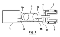
図1に関して、装置は、「バラスト」1、直列で搭載された2つのUVランプ2、3及びケーブル5を含み、ケーブルは、バラスト1とこれらのUVランプを接続するのに30mもの長さであってよい。これらのランプ2、3は、それぞれ4つのコネクタを有する。
With reference to FIG. 1, the apparatus comprises a “ballast” 1, two UV lamps 2, 3 and a
本発明により、ランプ2、3のウォーミングアップ手段4は、ランプのごく近傍に設けられる。従って、ケーブル5は、2本の導線5a及び5bのみからなり、また場合によっては5a、5bと点線で示されたシールドとからなる。
According to the invention, the warm-up means 4 for the lamps 2 and 3 are provided in the immediate vicinity of the lamps. Accordingly, the
図2は、図1に示された装置に対応する電気回路図を示す。図1により、ランプのごく近傍に設けられた電力供給の部品は、電流制御遠隔様式でランプをウォーミングアップする。 FIG. 2 shows an electrical circuit diagram corresponding to the apparatus shown in FIG. According to FIG. 1, the power supply component located in the immediate vicinity of the lamp warms up the lamp in a current controlled remote manner.
この図により、バラスト1は、2つのスイッチ1b、1cにより方形信号を出力する、可変周波数制御を備えた電子コンバーター1aと、電流の調節のためのコイル1d(インダクタンスとも呼ばれる)と、2つのコンデンサー1f、1gとを含む。
According to this figure, the ballast 1 includes an
ランプのごく近傍に設けられた電力供給部品は、モジュール6を形成し、少なくとも1つのコンデンサー4a及び1つの変圧器4bを含む。
The power supply component provided in the immediate vicinity of the lamp forms a module 6 and includes at least one
モジュール6は、2本の導線5a、5bを経てバラスト1に接続する。従来技術と比較して、直列で搭載されたランプとバラストとの間の導線の数は、このように、3又は4分の1に減じられ、配線のインダクタンス及び寄生容量並びにバラストとランプの正常な動作へのこれらの相対的影響を限定する。その結果、この配置は、エネルギーコスト及び装置の使用コストを減じることができる一方、非常に長いケーブルを有することを可能にする。
The module 6 is connected to the ballast 1 via two
図3は、ランプ2、3が、並列で設置され、電流制御ウォーミングアップをまだ使用する、本発明による装置の他の実施態様に関する電気回路図を示す。 FIG. 3 shows an electrical schematic for another embodiment of the device according to the invention, in which the lamps 2, 3 are installed in parallel and still use current-controlled warm-up.
この実施態様では、バラスト1は、発電機1a、2つのスィッチ1b、1c、2つのコイル1d、1e及び2つのコンデンサー1f、1gを含む。
In this embodiment, the ballast 1 includes a
ランプのごく近傍に設けられ、ウォーミングアップに関与する部品は、全て、モジュール6に含まれ、かつ2つのコンデンサー4c、4dを含む。
All components that are provided in the immediate vicinity of the lamp and are involved in warming up are included in the module 6 and include two
この実施態様により、ランプをバラスト1に接続する導線数は、5a、5b、5cの3本に減じられる。 According to this embodiment, the number of conductors connecting the lamp to the ballast 1 is reduced to three, 5a, 5b and 5c.
前記の両実施態様において、モジュール6は、非常に小さく、ランプソケット中に又はその真後ろに配置することができる。 In both embodiments described above, the module 6 is very small and can be placed in or just behind the lamp socket.
本発明により、他の実施態様を想定することもできよう。
特に、ランプを、電圧制御ウォーミングアップ可能な電気部品により暖めることができる。
Other embodiments could be envisaged by the present invention.
In particular, the lamp can be warmed by electrical components capable of voltage controlled warm-up.
装置が、2より多い数の放電ランプを含んでよいことは明らかである。 Obviously, the device may include more than two discharge lamps.
これらの放電ランプは、直列又は並列又は直列並列アセンブリーで搭載することができる。 These discharge lamps can be mounted in series or parallel or in a series-parallel assembly.
Claims (11)
ランプのウォーミングアップ及び点火手段と、
ランプの正常動作を達成する手段と
を含む、電力供給手段に電線で接続された、紫外線による水殺菌装置であって、
前記ウォーミングアップ手段の電気部品少なくとも1つが、前記ランプのごく近傍に設けられ、前記電力供給手段の他の部品が、それらから少し離れて設けられている、水殺菌装置。 Including at least two discharge lamps, said lamps comprising:
Lamp warm-up and ignition means;
A water sterilization apparatus using ultraviolet rays, connected to a power supply means by an electric wire, including means for achieving normal operation of the lamp,
A water sterilizer, wherein at least one electrical component of the warming-up means is provided in the immediate vicinity of the lamp, and other parts of the power supply means are provided a little away from them.
11. A water sterilization facility using ultraviolet rays, comprising at least one device according to claim 9 or 10.
Applications Claiming Priority (2)
| Application Number | Priority Date | Filing Date | Title |
|---|---|---|---|
| FR0315343A FR2864066B1 (en) | 2003-12-23 | 2003-12-23 | DEVICE FOR SUPPLYING UV LAMPS USED IN THE TREATMENT OF WATER |
| PCT/FR2004/003145 WO2005070834A1 (en) | 2003-12-23 | 2004-12-07 | Supply device for ultraviolet lamps used in the treatment of water |
Publications (2)
| Publication Number | Publication Date |
|---|---|
| JP2007515282A true JP2007515282A (en) | 2007-06-14 |
| JP2007515282A5 JP2007515282A5 (en) | 2008-01-31 |
Family
ID=34630548
Family Applications (1)
| Application Number | Title | Priority Date | Filing Date |
|---|---|---|---|
| JP2006546224A Pending JP2007515282A (en) | 2003-12-23 | 2004-12-07 | Feeding device for UV lamp used for water treatment |
Country Status (15)
| Country | Link |
|---|---|
| US (1) | US7645391B2 (en) |
| EP (1) | EP1776318A1 (en) |
| JP (1) | JP2007515282A (en) |
| KR (1) | KR20060131814A (en) |
| CN (1) | CN1898161B (en) |
| AU (1) | AU2004314278A1 (en) |
| BR (1) | BRPI0417968A (en) |
| CA (1) | CA2549027A1 (en) |
| FR (1) | FR2864066B1 (en) |
| MA (1) | MA28273A1 (en) |
| MX (1) | MXPA06007045A (en) |
| NO (1) | NO20062766L (en) |
| TN (1) | TNSN06198A1 (en) |
| WO (1) | WO2005070834A1 (en) |
| ZA (1) | ZA200604729B (en) |
Families Citing this family (5)
| Publication number | Priority date | Publication date | Assignee | Title |
|---|---|---|---|---|
| CN106421864A (en) * | 2009-01-29 | 2017-02-22 | S·E·内斯特尔 | Improved method and improved equipment for generating high disinfection effect in air and surface |
| JP5259562B2 (en) * | 2009-12-22 | 2013-08-07 | 株式会社東芝 | UV irradiation system |
| JP2011131138A (en) * | 2009-12-22 | 2011-07-07 | Toshiba Corp | Ultraviolet irradiation device |
| US10508047B2 (en) * | 2016-04-01 | 2019-12-17 | Gecko Alliance Group Inc. | Ultraviolet light water treatment system for bathing units |
| CN105858798A (en) * | 2016-04-14 | 2016-08-17 | 佛山市顺德区美的饮水机制造有限公司 | Ultraviolet sterilization device and control method thereof and faucet assembly with ultraviolet sterilization device |
Citations (1)
| Publication number | Priority date | Publication date | Assignee | Title |
|---|---|---|---|---|
| JPH1085734A (en) * | 1996-09-09 | 1998-04-07 | Janome Sewing Mach Co Ltd | Ultraviolet light sterilization device for water |
Family Cites Families (10)
| Publication number | Priority date | Publication date | Assignee | Title |
|---|---|---|---|---|
| US5368826A (en) * | 1992-12-04 | 1994-11-29 | Infilco Degremont, Inc. | Control apparatus for fluid disinfection modules and systems |
| US5698095A (en) * | 1993-01-28 | 1997-12-16 | Kami; Kazuhiko | Method and apparatus for human waste treatment |
| US5447630A (en) * | 1993-04-28 | 1995-09-05 | Rummler; John M. | Materials treatment process and apparatus |
| JPH09234457A (en) * | 1996-02-29 | 1997-09-09 | Takeshi Kishimoto | Non-drainage type night soil treatment by pulse combustion drying |
| US6673250B2 (en) * | 1999-06-21 | 2004-01-06 | Access Business Group International Llc | Radio frequency identification system for a fluid treatment system |
| US6731071B2 (en) * | 1999-06-21 | 2004-05-04 | Access Business Group International Llc | Inductively powered lamp assembly |
| US6181076B1 (en) * | 1999-08-19 | 2001-01-30 | Osram Sylvania Inc. | Apparatus and method for operating a high intensity gas discharge lamp ballast |
| DE10016982A1 (en) * | 2000-04-06 | 2001-10-25 | Wedeco Ag | Method for feeding a UV light low pressure lamp and ballast for feeding a UV light low pressure lamp |
| CA2323299A1 (en) * | 2000-10-12 | 2002-04-12 | Photoscience Japan Corporation | Water treatment assembly |
| US7211187B2 (en) * | 2004-10-29 | 2007-05-01 | Steven Lumbert | Mobile or stationary modular self-contained dehydration toilet, dehydration engine, and gray water recovery system |
-
2003
- 2003-12-23 FR FR0315343A patent/FR2864066B1/en not_active Expired - Fee Related
-
2004
- 2004-11-09 MX MXPA06007045A patent/MXPA06007045A/en not_active Application Discontinuation
- 2004-12-07 KR KR1020067014883A patent/KR20060131814A/en active IP Right Grant
- 2004-12-07 US US10/583,702 patent/US7645391B2/en not_active Expired - Fee Related
- 2004-12-07 AU AU2004314278A patent/AU2004314278A1/en not_active Abandoned
- 2004-12-07 CN CN2004800386707A patent/CN1898161B/en not_active Expired - Fee Related
- 2004-12-07 WO PCT/FR2004/003145 patent/WO2005070834A1/en active Application Filing
- 2004-12-07 JP JP2006546224A patent/JP2007515282A/en active Pending
- 2004-12-07 EP EP04805656A patent/EP1776318A1/en not_active Withdrawn
- 2004-12-07 CA CA002549027A patent/CA2549027A1/en not_active Abandoned
- 2004-12-07 BR BRPI0417968-4A patent/BRPI0417968A/en not_active Application Discontinuation
-
2006
- 2006-06-09 ZA ZA200604729A patent/ZA200604729B/en unknown
- 2006-06-13 NO NO20062766A patent/NO20062766L/en not_active Application Discontinuation
- 2006-06-22 TN TNP2006000198A patent/TNSN06198A1/en unknown
- 2006-06-26 MA MA29137A patent/MA28273A1/en unknown
Patent Citations (1)
| Publication number | Priority date | Publication date | Assignee | Title |
|---|---|---|---|---|
| JPH1085734A (en) * | 1996-09-09 | 1998-04-07 | Janome Sewing Mach Co Ltd | Ultraviolet light sterilization device for water |
Also Published As
| Publication number | Publication date |
|---|---|
| FR2864066B1 (en) | 2006-04-14 |
| TNSN06198A1 (en) | 2007-11-15 |
| CA2549027A1 (en) | 2005-08-04 |
| US7645391B2 (en) | 2010-01-12 |
| KR20060131814A (en) | 2006-12-20 |
| AU2004314278A1 (en) | 2005-08-04 |
| CN1898161B (en) | 2010-07-14 |
| ZA200604729B (en) | 2007-09-26 |
| MXPA06007045A (en) | 2006-08-31 |
| FR2864066A1 (en) | 2005-06-24 |
| EP1776318A1 (en) | 2007-04-25 |
| MA28273A1 (en) | 2006-11-01 |
| CN1898161A (en) | 2007-01-17 |
| US20070251886A1 (en) | 2007-11-01 |
| BRPI0417968A (en) | 2007-03-27 |
| WO2005070834A1 (en) | 2005-08-04 |
| NO20062766L (en) | 2006-07-14 |
Similar Documents
| Publication | Publication Date | Title |
|---|---|---|
| JP5096318B2 (en) | Electronic lamp identification system | |
| JP2003501242A (en) | Radiation source assembly for use with fluids | |
| US6507028B2 (en) | Radiation source module | |
| CA2219578A1 (en) | Non-electrode discharge lamp apparatus and liquid treatment apparatus using such lamp apparatus | |
| ZA200604729B (en) | Supply device for ultraviolet lamps used in the treatment of water | |
| IL123029A0 (en) | A method and device for operating electronic ballasts for high intensity discharge (HID) lamps | |
| US20020101185A1 (en) | Discharge lamps | |
| CN101514783B (en) | Ultraviolet irradiation apparatus | |
| WO2002032195A2 (en) | Discharge lamps preheating | |
| JP2007515282A5 (en) | ||
| JP2001029947A (en) | Ultraviolet liquid treatment device | |
| CA2409380A1 (en) | Ballast device for uv emitter and method and device for disinfection of water | |
| KR100309551B1 (en) | Device for generating radiant rays and ions having high activity | |
| ATE432606T1 (en) | ELECTRONIC BALLAST | |
| NL1037530C2 (en) | METHOD AND DEVICE FOR A GAS DISCHARGE LAMP. | |
| KR100296866B1 (en) | Electrostatic induction apparatus for producing high active radiant lights and ions | |
| NL1038724C2 (en) | METHOD AND DEVICE FOR A GAS DISCHARGE LAMP AS THE ELECTRODE FOR THE PRODUCTION OF OZONE OR RADICALS. | |
| CA2394665C (en) | Radiation source module | |
| JP2005251480A (en) | Discharge lamp driving device | |
| KR20010002028A (en) | An ozonizer | |
| JPH08273872A (en) | Low pressure mercury discharge lamp lighting device and ultraviolet ray irradiation device | |
| JPH05335089A (en) | Discharge lamp lighting device | |
| JPH0924090A (en) | Electronic ballast for ultraviolet irradiation unit | |
| JP2001185377A (en) | Light controller for inserting type fluorescent lamp | |
| KR20000012150A (en) | Discharge induction apparatus for producing high active radiant lights and ions using electric bulb |
Legal Events
| Date | Code | Title | Description |
|---|---|---|---|
| A521 | Written amendment |
Free format text: JAPANESE INTERMEDIATE CODE: A523 Effective date: 20071206 |
|
| A621 | Written request for application examination |
Free format text: JAPANESE INTERMEDIATE CODE: A621 Effective date: 20071206 |
|
| A977 | Report on retrieval |
Free format text: JAPANESE INTERMEDIATE CODE: A971007 Effective date: 20100528 |
|
| A131 | Notification of reasons for refusal |
Free format text: JAPANESE INTERMEDIATE CODE: A131 Effective date: 20100601 |
|
| A02 | Decision of refusal |
Free format text: JAPANESE INTERMEDIATE CODE: A02 Effective date: 20101029 |