JP2007514460A - Sensor showing increased biocompatibility - Google Patents
Sensor showing increased biocompatibility Download PDFInfo
- Publication number
- JP2007514460A JP2007514460A JP2006534128A JP2006534128A JP2007514460A JP 2007514460 A JP2007514460 A JP 2007514460A JP 2006534128 A JP2006534128 A JP 2006534128A JP 2006534128 A JP2006534128 A JP 2006534128A JP 2007514460 A JP2007514460 A JP 2007514460A
- Authority
- JP
- Japan
- Prior art keywords
- sensor
- membrane
- cavity
- biosensor
- electrochemical
- Prior art date
- Legal status (The legal status is an assumption and is not a legal conclusion. Google has not performed a legal analysis and makes no representation as to the accuracy of the status listed.)
- Pending
Links
- 239000003153 chemical reaction reagent Substances 0.000 claims abstract description 73
- 239000000463 material Substances 0.000 claims abstract description 46
- 239000011159 matrix material Substances 0.000 claims abstract description 35
- 239000012530 fluid Substances 0.000 claims abstract description 33
- 238000000034 method Methods 0.000 claims abstract description 20
- 102000004190 Enzymes Human genes 0.000 claims abstract description 18
- 108090000790 Enzymes Proteins 0.000 claims abstract description 18
- 239000003054 catalyst Substances 0.000 claims abstract description 14
- 239000011230 binding agent Substances 0.000 claims abstract description 7
- 239000012528 membrane Substances 0.000 claims description 136
- 239000012491 analyte Substances 0.000 claims description 62
- 239000004020 conductor Substances 0.000 claims description 31
- 239000000758 substrate Substances 0.000 claims description 31
- 238000007920 subcutaneous administration Methods 0.000 claims description 29
- 238000009792 diffusion process Methods 0.000 claims description 24
- 238000001514 detection method Methods 0.000 claims description 23
- WQZGKKKJIJFFOK-GASJEMHNSA-N Glucose Natural products OC[C@H]1OC(O)[C@H](O)[C@@H](O)[C@@H]1O WQZGKKKJIJFFOK-GASJEMHNSA-N 0.000 claims description 19
- 239000008103 glucose Substances 0.000 claims description 19
- 238000001727 in vivo Methods 0.000 claims description 19
- QVGXLLKOCUKJST-UHFFFAOYSA-N atomic oxygen Chemical compound [O] QVGXLLKOCUKJST-UHFFFAOYSA-N 0.000 claims description 17
- 229940088598 enzyme Drugs 0.000 claims description 17
- 229910052760 oxygen Inorganic materials 0.000 claims description 17
- 239000001301 oxygen Substances 0.000 claims description 17
- 210000001124 body fluid Anatomy 0.000 claims description 14
- NUJOXMJBOLGQSY-UHFFFAOYSA-N manganese dioxide Chemical compound O=[Mn]=O NUJOXMJBOLGQSY-UHFFFAOYSA-N 0.000 claims description 14
- OKTJSMMVPCPJKN-UHFFFAOYSA-N Carbon Chemical compound [C] OKTJSMMVPCPJKN-UHFFFAOYSA-N 0.000 claims description 12
- 229910052799 carbon Inorganic materials 0.000 claims description 12
- 238000005259 measurement Methods 0.000 claims description 12
- 239000010839 body fluid Substances 0.000 claims description 11
- 239000012510 hollow fiber Substances 0.000 claims description 8
- 239000002245 particle Substances 0.000 claims description 7
- 238000012360 testing method Methods 0.000 claims description 7
- 108010015776 Glucose oxidase Proteins 0.000 claims description 6
- 239000004366 Glucose oxidase Substances 0.000 claims description 6
- 239000004952 Polyamide Substances 0.000 claims description 6
- 239000004642 Polyimide Substances 0.000 claims description 6
- 229940116332 glucose oxidase Drugs 0.000 claims description 6
- 235000019420 glucose oxidase Nutrition 0.000 claims description 6
- 229920002647 polyamide Polymers 0.000 claims description 6
- 229920001721 polyimide Polymers 0.000 claims description 6
- 229920000642 polymer Polymers 0.000 claims description 6
- 230000004044 response Effects 0.000 claims description 6
- 239000013060 biological fluid Substances 0.000 claims description 5
- 239000007788 liquid Substances 0.000 claims description 3
- 239000012811 non-conductive material Substances 0.000 claims description 3
- 239000000376 reactant Substances 0.000 claims description 3
- 239000012891 Ringer solution Substances 0.000 claims description 2
- 229920000249 biocompatible polymer Polymers 0.000 claims description 2
- 238000000502 dialysis Methods 0.000 claims description 2
- 238000011049 filling Methods 0.000 claims description 2
- 125000002791 glucosyl group Chemical group C1([C@H](O)[C@@H](O)[C@H](O)[C@H](O1)CO)* 0.000 claims description 2
- 206010033675 panniculitis Diseases 0.000 claims description 2
- 229920002492 poly(sulfone) Polymers 0.000 claims description 2
- 210000004304 subcutaneous tissue Anatomy 0.000 claims description 2
- 238000004070 electrodeposition Methods 0.000 claims 3
- 239000000853 adhesive Substances 0.000 claims 1
- 230000001070 adhesive effect Effects 0.000 claims 1
- 238000006243 chemical reaction Methods 0.000 abstract description 17
- 238000004519 manufacturing process Methods 0.000 abstract description 10
- 239000000126 substance Substances 0.000 abstract description 4
- 230000008021 deposition Effects 0.000 abstract 2
- 239000010410 layer Substances 0.000 description 30
- 238000000576 coating method Methods 0.000 description 12
- 239000000203 mixture Substances 0.000 description 11
- 210000001519 tissue Anatomy 0.000 description 11
- 239000011248 coating agent Substances 0.000 description 9
- 238000005538 encapsulation Methods 0.000 description 8
- 208000005422 Foreign-Body reaction Diseases 0.000 description 7
- 102000004169 proteins and genes Human genes 0.000 description 7
- 108090000623 proteins and genes Proteins 0.000 description 7
- MHAJPDPJQMAIIY-UHFFFAOYSA-N Hydrogen peroxide Chemical compound OO MHAJPDPJQMAIIY-UHFFFAOYSA-N 0.000 description 6
- 238000001179 sorption measurement Methods 0.000 description 6
- 238000013459 approach Methods 0.000 description 5
- 230000008901 benefit Effects 0.000 description 5
- 150000001875 compounds Chemical class 0.000 description 5
- 238000013461 design Methods 0.000 description 5
- 238000001690 micro-dialysis Methods 0.000 description 5
- 229920005596 polymer binder Polymers 0.000 description 5
- 239000002491 polymer binding agent Substances 0.000 description 5
- 230000035945 sensitivity Effects 0.000 description 5
- 239000002904 solvent Substances 0.000 description 5
- 230000033115 angiogenesis Effects 0.000 description 4
- 238000004891 communication Methods 0.000 description 4
- 230000000694 effects Effects 0.000 description 4
- 230000006870 function Effects 0.000 description 4
- 230000035699 permeability Effects 0.000 description 4
- 230000008569 process Effects 0.000 description 4
- 102000008186 Collagen Human genes 0.000 description 3
- 108010035532 Collagen Proteins 0.000 description 3
- 230000001413 cellular effect Effects 0.000 description 3
- 230000008859 change Effects 0.000 description 3
- 229920001436 collagen Polymers 0.000 description 3
- 231100000135 cytotoxicity Toxicity 0.000 description 3
- 230000003013 cytotoxicity Effects 0.000 description 3
- 238000000835 electrochemical detection Methods 0.000 description 3
- PCHJSUWPFVWCPO-UHFFFAOYSA-N gold Chemical compound [Au] PCHJSUWPFVWCPO-UHFFFAOYSA-N 0.000 description 3
- 229910052737 gold Inorganic materials 0.000 description 3
- 239000010931 gold Substances 0.000 description 3
- 238000002513 implantation Methods 0.000 description 3
- 238000012986 modification Methods 0.000 description 3
- 230000004048 modification Effects 0.000 description 3
- 238000007254 oxidation reaction Methods 0.000 description 3
- 239000000243 solution Substances 0.000 description 3
- 231100000167 toxic agent Toxicity 0.000 description 3
- RZVAJINKPMORJF-UHFFFAOYSA-N Acetaminophen Chemical compound CC(=O)NC1=CC=C(O)C=C1 RZVAJINKPMORJF-UHFFFAOYSA-N 0.000 description 2
- CIWBSHSKHKDKBQ-JLAZNSOCSA-N Ascorbic acid Chemical compound OC[C@H](O)[C@H]1OC(=O)C(O)=C1O CIWBSHSKHKDKBQ-JLAZNSOCSA-N 0.000 description 2
- 229920000557 Nafion® Polymers 0.000 description 2
- 108090000854 Oxidoreductases Proteins 0.000 description 2
- 102000004316 Oxidoreductases Human genes 0.000 description 2
- KDLHZDBZIXYQEI-UHFFFAOYSA-N Palladium Chemical compound [Pd] KDLHZDBZIXYQEI-UHFFFAOYSA-N 0.000 description 2
- 229910021607 Silver chloride Inorganic materials 0.000 description 2
- 238000009825 accumulation Methods 0.000 description 2
- 230000009471 action Effects 0.000 description 2
- 239000000654 additive Substances 0.000 description 2
- 238000004458 analytical method Methods 0.000 description 2
- 239000008280 blood Substances 0.000 description 2
- 210000004369 blood Anatomy 0.000 description 2
- 210000004027 cell Anatomy 0.000 description 2
- 230000002708 enhancing effect Effects 0.000 description 2
- 229920002313 fluoropolymer Polymers 0.000 description 2
- 230000035876 healing Effects 0.000 description 2
- 238000012623 in vivo measurement Methods 0.000 description 2
- 208000014674 injury Diseases 0.000 description 2
- 229910052751 metal Inorganic materials 0.000 description 2
- 239000002184 metal Substances 0.000 description 2
- 230000003647 oxidation Effects 0.000 description 2
- 238000000059 patterning Methods 0.000 description 2
- 239000012071 phase Substances 0.000 description 2
- 150000003904 phospholipids Chemical class 0.000 description 2
- BASFCYQUMIYNBI-UHFFFAOYSA-N platinum Chemical compound [Pt] BASFCYQUMIYNBI-UHFFFAOYSA-N 0.000 description 2
- 229920001296 polysiloxane Polymers 0.000 description 2
- 239000011527 polyurethane coating Substances 0.000 description 2
- 239000011148 porous material Substances 0.000 description 2
- 230000001737 promoting effect Effects 0.000 description 2
- 238000007650 screen-printing Methods 0.000 description 2
- HKZLPVFGJNLROG-UHFFFAOYSA-M silver monochloride Chemical compound [Cl-].[Ag+] HKZLPVFGJNLROG-UHFFFAOYSA-M 0.000 description 2
- 231100000331 toxic Toxicity 0.000 description 2
- 230000002588 toxic effect Effects 0.000 description 2
- 230000008733 trauma Effects 0.000 description 2
- 238000003466 welding Methods 0.000 description 2
- 102000016938 Catalase Human genes 0.000 description 1
- 108010053835 Catalase Proteins 0.000 description 1
- 102000004127 Cytokines Human genes 0.000 description 1
- 108090000695 Cytokines Proteins 0.000 description 1
- XTHFKEDIFFGKHM-UHFFFAOYSA-N Dimethoxyethane Chemical compound COCCOC XTHFKEDIFFGKHM-UHFFFAOYSA-N 0.000 description 1
- RYECOJGRJDOGPP-UHFFFAOYSA-N Ethylurea Chemical compound CCNC(N)=O RYECOJGRJDOGPP-UHFFFAOYSA-N 0.000 description 1
- 206010061218 Inflammation Diseases 0.000 description 1
- OFOBLEOULBTSOW-UHFFFAOYSA-L Malonate Chemical compound [O-]C(=O)CC([O-])=O OFOBLEOULBTSOW-UHFFFAOYSA-L 0.000 description 1
- 206010067584 Type 1 diabetes mellitus Diseases 0.000 description 1
- LEHOTFFKMJEONL-UHFFFAOYSA-N Uric Acid Chemical compound N1C(=O)NC(=O)C2=C1NC(=O)N2 LEHOTFFKMJEONL-UHFFFAOYSA-N 0.000 description 1
- TVWHNULVHGKJHS-UHFFFAOYSA-N Uric acid Natural products N1C(=O)NC(=O)C2NC(=O)NC21 TVWHNULVHGKJHS-UHFFFAOYSA-N 0.000 description 1
- 239000013543 active substance Substances 0.000 description 1
- 239000007864 aqueous solution Substances 0.000 description 1
- 235000010323 ascorbic acid Nutrition 0.000 description 1
- 229960005070 ascorbic acid Drugs 0.000 description 1
- 239000011668 ascorbic acid Substances 0.000 description 1
- WQZGKKKJIJFFOK-VFUOTHLCSA-N beta-D-glucose Chemical compound OC[C@H]1O[C@@H](O)[C@H](O)[C@@H](O)[C@@H]1O WQZGKKKJIJFFOK-VFUOTHLCSA-N 0.000 description 1
- 239000012620 biological material Substances 0.000 description 1
- 239000006227 byproduct Substances 0.000 description 1
- 239000002775 capsule Substances 0.000 description 1
- 230000021164 cell adhesion Effects 0.000 description 1
- 230000005779 cell damage Effects 0.000 description 1
- 230000010261 cell growth Effects 0.000 description 1
- 229910010293 ceramic material Inorganic materials 0.000 description 1
- 238000003486 chemical etching Methods 0.000 description 1
- 239000003795 chemical substances by application Substances 0.000 description 1
- GTKRFUAGOKINCA-UHFFFAOYSA-M chlorosilver;silver Chemical compound [Ag].[Ag]Cl GTKRFUAGOKINCA-UHFFFAOYSA-M 0.000 description 1
- 239000012459 cleaning agent Substances 0.000 description 1
- 238000004132 cross linking Methods 0.000 description 1
- 230000003111 delayed effect Effects 0.000 description 1
- 230000000779 depleting effect Effects 0.000 description 1
- 238000003745 diagnosis Methods 0.000 description 1
- 230000004069 differentiation Effects 0.000 description 1
- 238000005553 drilling Methods 0.000 description 1
- 238000003487 electrochemical reaction Methods 0.000 description 1
- 239000007772 electrode material Substances 0.000 description 1
- -1 electrode structures Substances 0.000 description 1
- 239000008393 encapsulating agent Substances 0.000 description 1
- 238000005516 engineering process Methods 0.000 description 1
- 230000002255 enzymatic effect Effects 0.000 description 1
- 238000000605 extraction Methods 0.000 description 1
- 239000000835 fiber Substances 0.000 description 1
- 210000002950 fibroblast Anatomy 0.000 description 1
- 239000011888 foil Substances 0.000 description 1
- 238000009472 formulation Methods 0.000 description 1
- 150000002303 glucose derivatives Chemical class 0.000 description 1
- 239000003292 glue Substances 0.000 description 1
- 238000010438 heat treatment Methods 0.000 description 1
- 229920001477 hydrophilic polymer Polymers 0.000 description 1
- 230000002209 hydrophobic effect Effects 0.000 description 1
- 230000006872 improvement Effects 0.000 description 1
- 230000008595 infiltration Effects 0.000 description 1
- 238000001764 infiltration Methods 0.000 description 1
- 210000004969 inflammatory cell Anatomy 0.000 description 1
- 230000004054 inflammatory process Effects 0.000 description 1
- 230000003993 interaction Effects 0.000 description 1
- 230000003834 intracellular effect Effects 0.000 description 1
- 238000010030 laminating Methods 0.000 description 1
- 150000002605 large molecules Chemical class 0.000 description 1
- 238000000608 laser ablation Methods 0.000 description 1
- 229920002521 macromolecule Polymers 0.000 description 1
- 210000002540 macrophage Anatomy 0.000 description 1
- 238000010002 mechanical finishing Methods 0.000 description 1
- 238000010297 mechanical methods and process Methods 0.000 description 1
- 230000007246 mechanism Effects 0.000 description 1
- 230000005012 migration Effects 0.000 description 1
- 238000013508 migration Methods 0.000 description 1
- 238000002156 mixing Methods 0.000 description 1
- 230000037125 natural defense Effects 0.000 description 1
- 230000017095 negative regulation of cell growth Effects 0.000 description 1
- 229910000510 noble metal Inorganic materials 0.000 description 1
- 239000003960 organic solvent Substances 0.000 description 1
- 229910052763 palladium Inorganic materials 0.000 description 1
- 229960005489 paracetamol Drugs 0.000 description 1
- 230000002093 peripheral effect Effects 0.000 description 1
- 239000004033 plastic Substances 0.000 description 1
- 229920003023 plastic Polymers 0.000 description 1
- 229910052697 platinum Inorganic materials 0.000 description 1
- 229920000728 polyester Polymers 0.000 description 1
- 238000012545 processing Methods 0.000 description 1
- 239000000047 product Substances 0.000 description 1
- 238000011084 recovery Methods 0.000 description 1
- 230000009467 reduction Effects 0.000 description 1
- 238000000926 separation method Methods 0.000 description 1
- 229920005573 silicon-containing polymer Polymers 0.000 description 1
- 229920006268 silicone film Polymers 0.000 description 1
- 150000003384 small molecules Chemical class 0.000 description 1
- 239000007787 solid Substances 0.000 description 1
- 239000007790 solid phase Substances 0.000 description 1
- 125000006850 spacer group Chemical group 0.000 description 1
- 238000013222 sprague-dawley male rat Methods 0.000 description 1
- 238000004544 sputter deposition Methods 0.000 description 1
- 230000006641 stabilisation Effects 0.000 description 1
- 238000011105 stabilization Methods 0.000 description 1
- 238000003860 storage Methods 0.000 description 1
- 239000002344 surface layer Substances 0.000 description 1
- 230000000451 tissue damage Effects 0.000 description 1
- 231100000827 tissue damage Toxicity 0.000 description 1
- 229940116269 uric acid Drugs 0.000 description 1
- 238000007740 vapor deposition Methods 0.000 description 1
- XLYOFNOQVPJJNP-UHFFFAOYSA-N water Substances O XLYOFNOQVPJJNP-UHFFFAOYSA-N 0.000 description 1
- 238000001039 wet etching Methods 0.000 description 1
- 238000009736 wetting Methods 0.000 description 1
- 230000029663 wound healing Effects 0.000 description 1
Images


Classifications
-
- A—HUMAN NECESSITIES
- A61—MEDICAL OR VETERINARY SCIENCE; HYGIENE
- A61B—DIAGNOSIS; SURGERY; IDENTIFICATION
- A61B5/00—Measuring for diagnostic purposes; Identification of persons
- A61B5/145—Measuring characteristics of blood in vivo, e.g. gas concentration, pH value; Measuring characteristics of body fluids or tissues, e.g. interstitial fluid, cerebral tissue
- A61B5/1486—Measuring characteristics of blood in vivo, e.g. gas concentration, pH value; Measuring characteristics of body fluids or tissues, e.g. interstitial fluid, cerebral tissue using enzyme electrodes, e.g. with immobilised oxidase
- A61B5/14865—Measuring characteristics of blood in vivo, e.g. gas concentration, pH value; Measuring characteristics of body fluids or tissues, e.g. interstitial fluid, cerebral tissue using enzyme electrodes, e.g. with immobilised oxidase invasive, e.g. introduced into the body by a catheter or needle or using implanted sensors
-
- A—HUMAN NECESSITIES
- A61—MEDICAL OR VETERINARY SCIENCE; HYGIENE
- A61B—DIAGNOSIS; SURGERY; IDENTIFICATION
- A61B5/00—Measuring for diagnostic purposes; Identification of persons
- A61B5/145—Measuring characteristics of blood in vivo, e.g. gas concentration, pH value; Measuring characteristics of body fluids or tissues, e.g. interstitial fluid, cerebral tissue
- A61B5/14532—Measuring characteristics of blood in vivo, e.g. gas concentration, pH value; Measuring characteristics of body fluids or tissues, e.g. interstitial fluid, cerebral tissue for measuring glucose, e.g. by tissue impedance measurement
-
- C—CHEMISTRY; METALLURGY
- C12—BIOCHEMISTRY; BEER; SPIRITS; WINE; VINEGAR; MICROBIOLOGY; ENZYMOLOGY; MUTATION OR GENETIC ENGINEERING
- C12Q—MEASURING OR TESTING PROCESSES INVOLVING ENZYMES, NUCLEIC ACIDS OR MICROORGANISMS; COMPOSITIONS OR TEST PAPERS THEREFOR; PROCESSES OF PREPARING SUCH COMPOSITIONS; CONDITION-RESPONSIVE CONTROL IN MICROBIOLOGICAL OR ENZYMOLOGICAL PROCESSES
- C12Q1/00—Measuring or testing processes involving enzymes, nucleic acids or microorganisms; Compositions therefor; Processes of preparing such compositions
- C12Q1/001—Enzyme electrodes
- C12Q1/005—Enzyme electrodes involving specific analytes or enzymes
- C12Q1/006—Enzyme electrodes involving specific analytes or enzymes for glucose
-
- A—HUMAN NECESSITIES
- A61—MEDICAL OR VETERINARY SCIENCE; HYGIENE
- A61B—DIAGNOSIS; SURGERY; IDENTIFICATION
- A61B2562/00—Details of sensors; Constructional details of sensor housings or probes; Accessories for sensors
- A61B2562/02—Details of sensors specially adapted for in-vivo measurements
Abstract
センサーおよびセンサーの製造方法が開示されている。好ましい実施の形態において空洞が形成され、導電性マトリックス、酵素、触媒および結合剤を含む試薬で充填される。該空洞は、実質的に包囲されており、試料が入ることを可能にする開口が残される。空洞を取り囲む材料の一部は、好ましくは反応を測定するために有用な物質には透過性があるが、試薬または試料には透過性がない。円錐形、円錐台、角錐台および正円筒形を有する空洞が例として挙げられている。他のシステムは、センサーの活性領域を含み、流体の内部堆積を定義する膜を含み、該膜または内部堆積は活性領域に対して特定の幾何学関係を有している。 A sensor and a method for manufacturing the sensor are disclosed. In a preferred embodiment, cavities are formed and filled with a reagent comprising a conductive matrix, an enzyme, a catalyst and a binder. The cavity is substantially enclosed, leaving an opening that allows the sample to enter. The portion of the material surrounding the cavity is preferably permeable to substances useful for measuring the reaction, but not to the reagent or sample. Examples include cavities having a conical shape, a truncated cone, a truncated pyramid and a regular cylinder. Other systems include an active area of the sensor and a film that defines the internal deposition of the fluid, the film or internal deposition having a specific geometric relationship to the active area.
Description
本発明は、インビボ測定に関する。さらに詳細には、本発明は、体内の流動体における特定の物質の濃度の検出、および検出のためのセンサーに関する。 The present invention relates to in vivo measurements. More particularly, the present invention relates to the detection of the concentration of a specific substance in a fluid in the body and a sensor for detection.
体液中の特定の化合物の濃度の測定は、多くの型の医療診断および治療のために有用である。インスリン依存性糖尿病患者は、例えば、一日当たり複数回、彼らの血液中のグルコースの濃度を測定するかもしれない。インビボセンサーが開発されて、そして反復または継続した試験のための状況に有用であるが、しかし耐久性、精度、製造の容易さ、および使用時の可能性のある寿命で限定される。したがって、インビボセンサーおよび検出技術が改善される必要性がある。 Measurement of the concentration of a particular compound in bodily fluids is useful for many types of medical diagnosis and treatment. Insulin dependent diabetics may measure the concentration of glucose in their blood, for example, multiple times per day. In vivo sensors have been developed and are useful in situations for repeated or continued testing, but limited in durability, accuracy, ease of manufacture, and possible lifetime in use. Accordingly, there is a need for improved in vivo sensors and detection techniques.
膜を、それを通して分析物の流れを制御するために使用することによって、分析物と試薬との間の反応を限定するセンサーが開発されてきた。これらの膜を使用すると、設計経費、製造経費を増し、そしてこのようなセンサーを使用に困難である。したがって、インビボセンサーおよび検出技術が改善されることがさらに必要である。 Sensors have been developed that limit the reaction between analytes and reagents by using membranes to control the flow of analytes therethrough. Use of these membranes increases design and manufacturing costs and makes such sensors difficult to use. Therefore, there is a further need for improved in vivo sensors and detection techniques.
したがって、費用、精度、簡便さ、耐久性、およびインビボ寿命の改善された特徴を有する検出用のセンサーおよび技術を提供することが、本発明の種々の実施態様の目的である。 Accordingly, it is an object of various embodiments of the present invention to provide sensors and techniques for detection that have improved features of cost, accuracy, simplicity, durability, and in vivo lifetime.
これらの目的および他のものは、センサーの幾何学的配置を使用して、試料が電極に、または中に流れることを制限することによって、例えば、試薬を包含する電導性マトリックスを含む三次元空洞に小型開口部を供することによって、本発明のいくつかの実施態様で達成される。 These objectives and others use a sensor geometry to limit the flow of a sample to or into an electrode, for example, a three-dimensional cavity containing a conductive matrix containing reagents. This is achieved in some embodiments of the present invention by providing a small opening in the body.
本発明の1つの実施態様は、特定の化合物を電気化学的に検出または測定するインビボで使用するための電極である。第一(基材)層は、一方の末端または近隣に、計器に電気的接続に適合される接点を有する。該層およびその頂点表面が第一層の底部表面に実質的に隣接する第二層は、一緒に、第一層の頂点表面を通る開口部を有する空洞の範囲を明確にし、そしてその開口部は、第一層の第一末端から離れて離間されている。試薬は、空洞の少なくとも20パーセントを満たし、導電性マトリックスを包含し、そして接点に電気的に繋がっている。この実施態様のある種の変形では、第一層は、ポリイミドであり、そして他方では、第一層は、約2ミルと約10ミル、または約50μmと約250μmの間の厚みを有する。 One embodiment of the invention is an electrode for in vivo use to detect or measure a particular compound electrochemically. The first (substrate) layer has contacts at one end or near that are adapted for electrical connection to the instrument. The layer and the second layer whose apex surface is substantially adjacent to the bottom surface of the first layer together define a cavity having an opening through the apex surface of the first layer and the opening Are spaced apart from the first end of the first layer. The reagent fills at least 20 percent of the cavity, includes a conductive matrix, and is electrically connected to the contacts. In certain variations of this embodiment, the first layer is polyimide and, on the other hand, the first layer has a thickness between about 2 mils and about 10 mils, or between about 50 μm and about 250 μm.
本実施態様のさらに他の変形では、その空洞は、第一層の頂点表面を通るその開口部と特定の関係を示す。例えば、ある種の変形では、開口部に平行であるが、しかし試薬充填部分上に取られた空洞の各断面は、開口部の面積より小さくない面積を有する。他方では、試薬充填部分を横断する空洞の断面も、開口部と同様の大きさの面積を有する。この変形の微細な区別で、これらの断面の面積は、それらが、さらに開口部から取られる場合、単調に増大する。本実施態様の他の変動では、電極の体積または封じ込め空洞の体積のいずれかは、開口部の面積と特定の数値関係を示す。 In yet another variation of this embodiment, the cavity exhibits a specific relationship with the opening through the apex surface of the first layer. For example, in certain variations, each cross-section of the cavity that is parallel to the opening but taken over the reagent-filled portion has an area that is not less than the area of the opening. On the other hand, the cross section of the cavity that crosses the reagent filling portion also has an area of the same size as the opening. With this fine differentiation of deformation, the area of these cross sections increases monotonically as they are further taken from the opening. In other variations of this embodiment, either the volume of the electrode or the volume of the containment cavity exhibits a specific numerical relationship with the area of the opening.
本発明の別の形態は、頂上および底部表面を有する第一層、接点末端および検出末端、接点末端にまたはその近くに2つの接点、検出末端にまたはその近くに配置される電極、第一電極位置の近くに別の電極位置、および第一電極位置で主要層内にそれにより定義される空洞を含む、分析物の濃度または存在を試験するためのストリップである。空洞は、頂部表面を通る開口部を有し、そして試薬を包含する電導性マトリックスによって少なくとも約20パーセント充填されている。導電体は、空洞を接点の一方と電気的に接続する一方で、別の導電体は、他の電極位置と第二接点を電気的に接続する。 Another aspect of the invention is a first layer having a top and bottom surface, a contact end and a detection end, two contacts at or near the contact end, an electrode disposed at or near the detection end, a first electrode A strip for testing the concentration or presence of an analyte comprising another electrode location near the location and a cavity thereby defined in the main layer at the first electrode location. The cavity has an opening through the top surface and is at least about 20 percent filled with a conductive matrix containing reagents. A conductor electrically connects the cavity with one of the contacts, while another conductor electrically connects the other electrode location with the second contact.
本実施態様の変形で、分析物に非浸透性である1つまたは複数の材料によって、開口部以外は、空洞を実質的に囲む。本実施態様の微細な区分では、少なくとも1つのこれらの材料は、空洞に含まれる試薬のコファクターに透過性である。これは、例えば、試薬がグルコースオキシダーゼを包含するグルコースセンサーの場合には酸素であり得る。これらの変形のいくつかでは、1つまたは複数のコファクター透過性材料は、一方の側面が主要層の底部表面に隣接して配置される第二層を形成する。 In a variation of this embodiment, one or more materials that are impermeable to the analyte substantially enclose the cavity except for the opening. In the fine section of this embodiment, at least one of these materials is permeable to the cofactor of the reagent contained in the cavity. This can be, for example, oxygen if the reagent is a glucose sensor including glucose oxidase. In some of these variations, the one or more cofactor permeable materials form a second layer with one side located adjacent to the bottom surface of the main layer.
本実施態様における他の変形では、少なくとも空洞の一部は、コファクター透過性である材料により定義される。その材料は、第一層の底部表面に隣接してよい。他の変形では、電導性マトリックスは、空洞の体積の少なくとも約80パーセントを満たす。 In other variations of this embodiment, at least a portion of the cavity is defined by a material that is cofactor permeable. The material may be adjacent to the bottom surface of the first layer. In other variations, the conductive matrix fills at least about 80 percent of the volume of the cavity.
本実施態様におけるさらに他の変形では、その空洞に達する導電体は、それを少なくとも部分的に定義するために空洞まで拡張する。他方では、導電体は、頂部表面に沿って配置される一方で、さらに他方では、導電体は、主要層の底部表面に沿って配置される。さらに別の変形では、導電体マトリックスは、空洞を実質的に満たす。 In yet another variation on this embodiment, the conductor reaching the cavity extends to the cavity to at least partially define it. On the other hand, the conductor is arranged along the top surface, while on the other hand, the conductor is arranged along the bottom surface of the main layer. In yet another variation, the conductor matrix substantially fills the cavity.
本発明の別の実施態様では、電気化学的センサーは、基板、基板上の参照電極、および基板によって実質的に定義された空洞を実質的に満たす作用電極を含む。作用電極は、導電性マトリックスおよび酵素を含む。本実施態様の変形では、導電体マトリックスは炭素粒子を包含し、そして他方では、酵素はグルコースオキシダーゼである。本発明のさらに別の変形では、作用電極は二酸化マンガンのような触媒も含む。さらに別の変動では、電極は重合体のような結合剤も含み、そしてさらに、二酸化マンガンのような触媒を含み得る。これらの変形のいくつかでは、結合剤は重合体である。 In another embodiment of the invention, the electrochemical sensor includes a substrate, a reference electrode on the substrate, and a working electrode that substantially fills a cavity substantially defined by the substrate. The working electrode includes a conductive matrix and an enzyme. In a variation of this embodiment, the conductor matrix includes carbon particles and on the other hand the enzyme is glucose oxidase. In yet another variation of the invention, the working electrode also includes a catalyst such as manganese dioxide. In yet another variation, the electrode also includes a binder such as a polymer and may further include a catalyst such as manganese dioxide. In some of these variations, the binder is a polymer.
本実施態様の変形では、空洞は実質的に円筒形状を示す一方で、他方では、それは、実質的にピラミッド角錐台または円錐の形状を示す。後者の変形のいくつかでは、空洞は、分析物がその空洞を通過するのに十分に開放している小型円形表面、および酸素透過性材料に隣接する大型円形表面を有する。本実施態様のさらに別の変形では、作用電極の一方の表面は、試料が分析物の拡散を制限する層を通過することなく、電極に入ることができるように開放されている。 In a variation of this embodiment, the cavity exhibits a substantially cylindrical shape, while on the other hand it exhibits a substantially pyramidal pyramid or conical shape. In some of the latter variations, the cavity has a small circular surface that is sufficiently open for analytes to pass through the cavity and a large circular surface adjacent to the oxygen permeable material. In yet another variation of this embodiment, one surface of the working electrode is open so that the sample can enter the electrode without passing through a layer that limits analyte diffusion.
本発明の原理を理解することを促進する目的のために、ここで、図面で示された実施態様に言及し、そして特定の言語が、本発明を説明するために使用される。それにもかかわらず、本発明の範囲の制限が、それにより意図されるものはないことが理解される。記載または例示された実施態様の代替物またはさらなる改質、およびここに示されるとおり本発明の原理のあらゆる別の応用が、本発明が関連する当業者に通常に起こるものとして意図される。 For the purpose of promoting an understanding of the principles of the invention, reference will now be made to the embodiments illustrated in the drawings and specific language will be used to describe the invention. Nevertheless, it is understood that no limitation of the scope of the invention is thereby intended. Alternatives or further modifications of the described or illustrated embodiments, and any other application of the principles of the invention as shown herein are intended as would normally occur to those skilled in the art to which the invention pertains.
本発明の種々の実施態様は、ここで、(1)実質的に平面の電極を使用する場合、分析物反応および電気化学的検出が起こる実質的に平面の領域に該当すること、および(2)多孔質の導電性試薬マトリックスを使用する場合、多孔質の導電性マトリックスを含む体積を、体液の体積に接続する開口部の実質的に平面な領域に該当する、センサーの「活性領域」で分析物および干渉物の性質を有利な制御を供するためにセンサーの幾何学を利用する分析物センサーを提供する。センサーを、皮膚の下に移植し、そして測定されるべき分析物を含む周囲の体液と接触している部分を含む。一般に、センサーは、体液と接触している第一の表面、そしてセンサーから受けた電気信号に基づいて分析を評価するために操作可能な計器に戻って連通する導電性トレースの表面と接触している第二の表面を有する多孔質の導電性マトリックスを含む。多孔質試薬の操作領域は、流動体接触表面、または、導電性トレースの表面より明らかに大きく、これにより、より平面な設計と比較して、分析物の反応および電気化学的検出反応のために、そして電極での測定された反応の毒性副産物の捕捉のためにより大きな表面積を供する。 The various embodiments of the present invention now relate to (1) a substantially planar region where analyte reaction and electrochemical detection occur when using substantially planar electrodes, and (2 ) When using a porous conductive reagent matrix, the “active area” of the sensor, where the volume containing the porous conductive matrix corresponds to the substantially planar area of the opening connecting to the volume of body fluid An analyte sensor is provided that utilizes sensor geometry to provide advantageous control of analyte and interferent properties. The sensor is implanted under the skin and includes a portion in contact with the surrounding body fluid containing the analyte to be measured. In general, the sensor is in contact with the first surface that is in contact with the body fluid and the surface of the conductive trace that communicates back to an instrument operable to evaluate the analysis based on the electrical signal received from the sensor. And a porous conductive matrix having a second surface. The operating area of the porous reagent is clearly larger than the fluid contact surface or the surface of the conductive trace, which allows for analyte reactions and electrochemical detection reactions compared to the more planar design. , And provide a larger surface area for capture of toxic by-products of the measured reaction at the electrode.
特定の実施態様では、導電性マトリックスにより占有される体積は、一般に、流動体接触表面から離れて導電性トレース表面に向かって進行するときに、断面積において増大する。部分的に充填された空洞を有する他の場合では、空洞は、一般に、流動体接触開口部から離れて試薬の体積に下降して進行するときに、断面積において増大する。さらにほかには、空洞は、一般に、流動体接触表面から離れて進行するときに、断面積において増大する。 In certain embodiments, the volume occupied by the conductive matrix generally increases in cross-sectional area as it travels away from the fluid contact surface toward the conductive trace surface. In other cases with partially filled cavities, the cavities generally increase in cross-sectional area as they travel down from the fluid contact opening and into the reagent volume. Still further, the cavity generally increases in cross-sectional area as it travels away from the fluid contact surface.
いくつかの実施態様では、所定の体積を、基板を通して開放し、そして試薬をそこに入れる。開口上から空洞までの膜は、分析物に透過性があるが、所定の干渉物にはない。別の膜が、他の開口部を被覆し、そして分析物に非透過性である。この実施態様の変形では、第二膜は分析物を排除するために選択的に透過性があるが、しかし流動体中の1つまたはそれより多くのコファクター(酸素のような)を反応空洞に通過させる。 In some embodiments, a predetermined volume is released through the substrate and a reagent is placed therein. The membrane from the top of the opening to the cavity is permeable to the analyte but not the predetermined interferent. Another membrane covers the other opening and is impermeable to the analyte. In a variation of this embodiment, the second membrane is selectively permeable to exclude analytes, but allows one or more cofactors (such as oxygen) in the fluid to react to the reaction cavity. To pass through.
本発明のいくつかの実施態様は、電気化学的手段によって測定可能な広く多様な分析物の皮下検出に有用である。例の目的として、ここでの検討は、グルコースセンサーに関して提供され、そして化学および他の要素が識別されることに対応する。しかし、他の分析物を、本発明を使用して十分に検出し得ること、そして化学および同等物における対応の変化が、当業界で周知であることは、当業者によく理解される。 Some embodiments of the invention are useful for the subcutaneous detection of a wide variety of analytes that can be measured by electrochemical means. For purposes of example, the discussion here is provided for a glucose sensor and corresponds to the identification of chemistry and other factors. However, it is well understood by those skilled in the art that other analytes can be fully detected using the present invention, and corresponding changes in chemistry and equivalents are well known in the art.
特に図面に関して、図1は、本発明の1つの実施態様によるセンサーの構成要素を示す。センサーストリップ10は、ヘッド部分12および本体部分14を有する。ヘッド部分12は、電圧計、ポテンショスタット、電流計、および/または他の検出または表示構成要素に電気的に接続するための接点16、18および20を含む。接点は、電気化学的バイオセンサー技術で周知であるとおり、センサー中の電位および電流を制御し、そしてセンサーの検出部分から電気的信号を受取および評価するように作動するこのようなデバイスと直接的に、または間接的に接触させ得る。
With particular reference to the drawings, FIG. 1 shows the components of a sensor according to one embodiment of the present invention. The sensor strip 10 has a
本体部分14は、参照電極28、作用電極30、および対向電極29を含む。導電体トレース22は、参照電極28に接点16を接続し、導電体トレース24は、作用電極30に接点18を接続し、そして導電体トレース26は、対向電極29に接点20を接続する。下の実施例で検討されるとおり、これらの構造の各々は、基板32中または上に作製され、該基板は、好ましくは、ポリイミドまたはポリエステルのような、目的の分析物(類)に非透過性である材料の約2と約10ミルのあいだ(約50μmと約250μmのあいだ)の厚さを有する可塑性層である。トレース22、24および26は、好ましくは、金または炭素から製造されるが、しかし他の導電性材料も使用され得る。
The
本実施態様の1つの形態では、センサーストリップ10の本体部分14は、形状において、長さ約25mmそして幅450μmであるおよそ長方形であり、そして使用中に生物適合性を増大する中空繊維膜(図示せず)内に配置される。作用電極30は、長方形(図1でのとおり、上から見たときに少なくとも)であり、そして幅約100μm、そして長さ325μmである。作用電極30は、塗布に適した試薬混合物を含む。本実施態様の1つの形態では、試薬混合物は、(炭素粒子の)導電性マトリックス、触媒(二酸化マンガン)、酵素(グルコースオキシダーゼ)、重合体結合剤、および重合体結合体のための溶媒を包含する。溶媒の除去において、この試薬混合物は、基板32中の空洞を満たすか、または少なくとも実質的に満たして、電極30を形成する多孔質の導電性マトリックスを形成する。これらの構造の作製は下で検討される。これらの形態では、電極の平面部分がまったく小さい場合でさえ、多孔質試薬マトリックスは、反応のために多大な試薬表面積をさらす。封じ込め空洞の開口部は、空洞の中に、そして外に分析物による拡散を調節し、これは、いくつかの実施態様では、反応測定における変動の制御が改善されること、および測定精度において対応する改善を供する。
In one form of this embodiment, the
センサーを配置したとき、生物学的流動体が、作用電極30を含む空洞に入り、そして流動体中のグルコースは、酵素と反応し、そして作用電極30の電気的インピーダンス特性を変化させる。稼動回路を、それぞれ、接点18およびトレース24を介して電極30と、そして接点16および20を介して参照電極28と対向電極29と、そしてトレース22および26と電気的に連通させる。1つまたは複数の電極での電気的電位を制御し、そして当業で知られるとおり、生じる電流を分析して(または反対に)流動体中のグルコースの濃度を決定する。
When the sensor is placed, the biological fluid enters the cavity containing the working
種々の代替実施態様では、より多くのまたはより少ない電極が、当業者に理解されるであろうとおり、センサーストリップ10に含まれる。 In various alternative embodiments, more or fewer electrodes are included in the sensor strip 10 as will be appreciated by those skilled in the art.
流動体は、特定の結果を達成する特定の方法で一定の大きさに作られた空洞と接触している。これらの実施態様のいくつかは、形状でおよそ円筒形である封じ込め体積(他所での「空洞」)を含む。他の実施態様では、封じ込め体積の一方の末端は、実質的に他方より広くてよく、そこでは他方の末端で円形開口部の直径の二倍である直径を示す円形開口部など)分析物透過性膜が、小型開口部上であり、そして共反応体透過性膜は大型開口部上にあり、その結果分析物の移動は一方の側で制御され得るが、しかし十分な共反応体は他方の側を通して流体から獲得される。 The fluid is in contact with a cavity that is sized in a particular way to achieve a particular result. Some of these embodiments include a containment volume (a “cavity” elsewhere) that is approximately cylindrical in shape. In other embodiments, one end of the containment volume may be substantially wider than the other, where the other end has a diameter that is twice the diameter of the circular opening, such as a circular opening) The permeable membrane is on the small opening and the co-reactant permeable membrane is on the large opening so that analyte migration can be controlled on one side, but sufficient co-reactant is on the other Obtained from the fluid through the sides.
空洞内で、試薬、およびある場合には、コファクターは、周囲の体積から生物学的流動体の構成要素と反応する。電気的電位は、この反応位置で作り出され、そして試料中の分析物の濃度を測定する測定回路に運ばれなければならない。これらの好ましい実施態様では、空洞の体積は、空洞の重要な部分全体に試薬を存在し、そしてさらに(マトリックスの導電特性のため)空洞に、好ましくはそれの周囲表面で拡張する導電性トレースまで、反応位置で生じた電荷を運ぶ多孔質の導電性マトリックスで少なくとも約20%(好ましくは、少なくとも約50%、さらに好ましくは少なくとも約80%、そして最も好ましくは約100%)満たされる。導電性トレースは、基板の表面に、そして接点パット上に拡張し、該接点パットは、計器ユニットまたは他の試験回路と電気接触する。 Within the cavity, the reagents, and in some cases the cofactors, react with the components of the biological fluid from the surrounding volume. An electrical potential is created at this reaction site and must be conveyed to a measurement circuit that measures the concentration of the analyte in the sample. In these preferred embodiments, the volume of the cavity is up to a conductive trace that extends the reagent into the cavity, preferably at its peripheral surface (due to the conductive properties of the matrix), with the reagent present throughout the critical portion of the cavity. At least about 20% (preferably at least about 50%, more preferably at least about 80%, and most preferably about 100%) with a porous conductive matrix carrying the charge generated at the reaction site. The conductive traces extend to the surface of the substrate and onto the contact pads, which contact pads are in electrical contact with the instrument unit or other test circuit.
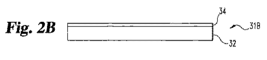
図1での所定の構造を引き続き参照しながら図2A〜2Gに変わり、本発明による一種のセンサーを作製する1つの方法を、ある程度図面形態で示されるものがある。図2Aは、基板32を示し、そしてそれは、当業者が想定するであろう、多かれ少なかれ堅い物質であり得る。例えば、基板32は、ポリイミド、セラミック材料、または別の材料であり得る。
With continued reference to the predetermined structure in FIG. 1, instead of FIGS. 2A-2G, one method of making a type of sensor according to the present invention is shown in some form in the drawing. FIG. 2A shows a
図2Bは、導電性材料の層34が、基板32上に配置されたことを示す。種々の実施態様では、導電性層34は、当業者が想定するであろうとおりのスパッタリング、蒸着、または別の方法によって溶着される。導電性層34を、例えばリソグラフまたはレーザー除去技術を使用してその後パターン化して、図2Cで示されるとおり、基板32上に導電体トレース22、24、および26を定義する。他の実施態様では、導電体トレース22、24、および26を、スクリーンプリント印刷または他のパターン化技術を使用して、基板32上にプリント印刷または別の方法で形成する。
FIG. 2B shows that a layer 34 of conductive material has been disposed on the
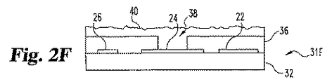
図2Dは、比較的非導電性の材料36の層が、導電体22、24、および26上に溶着されたことを示す。材料36は、当業者が想定するように、例えば、各々イー アイ デュポン・ド・ネモール・アンド・カンパニー(E.I.DuPont de Nemours and Company)(ここで「デュポン」)によって販売されるパイラウレックス(PYRALUX)またはバクレル(VACREL)または同等物であり得る。
FIG. 2D shows that a layer of relatively
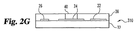
図2Eは、凹所38が、層36に作製されたことを示す。凹所38は、例えば、選択的化学エッチング、レーザー除去、または他の技術によって作り出される。その後、試薬40を、凹所38を含む構造31E上に溶着させて、図2Fに示されるとおり構造31Fを得る。試薬40は、炭素粒子のような導電性マトリックス、二酸化マンガンのような触媒、グルコースオキシダーゼのような酵素、および重合体結合剤を包含する。これらの構成要素は、典型的に、この溶着段階のあいだに有機溶媒中に分散される。過剰(上の材料36)は、スクイージー、化学的機械的仕上げ(CMP)、または類似の技術によって除去して、図2Gに示される構造31Gを得る。溶媒ベアリング試薬40を、加熱または真空により蒸散させて、試薬40が、凹所38を実質的に充填するようにする。他の実施態様では、試薬40は凹所38に直接溶着される。
FIG. 2E shows that a
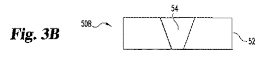
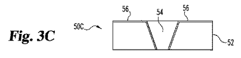
本発明によってセンサーを作製する別の方法は、ここで、図3A〜3Gに関連して記載される。デバイス50Aは、血液に対して透過性でない材料から製造される基板52を包含する。図3Bで示される空洞54は、抽出により基板52中に形成されて、デバイス50Bを作り出す。図3Cで示されるとおり、デバイス50Cは、凹所54に、そしてデバイス50Cの頂上表面に沿って拡張する導電性層56の追加と共に、デバイス50Bを包含する。
Another method of making a sensor according to the present invention will now be described in connection with FIGS.
導電体層56をパターン化して、図3Dで示されるデバイス50Dを形成する。導電体トレース22’、24’および26’は、一般に、図1中の導電体22、24、および26に対応する。試薬組成物58を、少なくとも凹所54を満たすのに十分なデバイス50Dの頂部に溶着させて、図3Eに示されるデバイス50Eを形成する。
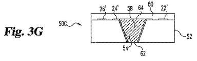
その後、過剰試薬58(基板52の上部表面上の)を除去して、図3Fに示されるデバイス50Fを得る。さらに、この除去を、スクイージー、CMP、または当業者が想定するであろう他の適切な工程によって行う。封入材料60の層を、デバイス50F上に重ね、図3Gで示されるようにデバイス50Gを形成する。使用時に、体液は、表面開口部62で導電性試薬58と直接接触する。検出のために使用される酸素または別の物質を、層60を通して、そして表面/開口部64を通して試薬58に輸送する。
Thereafter, excess reagent 58 (on the upper surface of substrate 52) is removed to obtain
本実施態様の1つの好ましい形態では、グルコースセンサー、基板52は、ポリアミドであり、そして封入層60はシリコーンである。導電体層56(およびしたがって、導電体トレース22’、24’および26’)は金である。試薬58は、酵素のための固定および安定化マトリックスとしてのみならず、活性電極要素としても機能する多孔質導電性マトリックス中に炭素粒子を包含する。凹所中の導電性マトリックス54は、導電体トレース24’と接触し、該導電体トレースは、作用電極から計器または他の回路に接続するための(図1で接点18のような)センサーのコネクター領域まで導電性経路を形成する。
In one preferred form of this embodiment, the glucose sensor,
他の実施態様では、コネクターは、別の金属であるか、または基板の表面に印刷またはそうでなければ溶着した炭素トレースである。さらに他の実施態様では、導電体を、凹所54内の周囲に溶着させ、凹所54の一方の壁に溶着させ、試薬58上に溶着させるか、またはそうでなければ、電極マトリックスと接触する。種々の実施態様では、(導電性マトリックスを含む)試薬混合物は、凹所54の少なくとも約20%を、好ましくは凹所54の少なくとも約80%、そして最も好ましくは凹所54の実質的に全てを満たす。凹所の残りは、当業者が想定するように、空気(未使用センサー中)、流動体(使用中のセンサー中)、または他の材料のいずれかを含有する。さらに他の実施態様では、凹所54は、それが、それを通して試料が電極に入る開口部64を横切る最短距離の幅の少なくとも半分くらい深く、そして好ましくは、凹所54は、少なくとも、それが、開口部64を横切る最短距離の幅と同程度に深い。
In other embodiments, the connector is another metal or carbon trace printed or otherwise deposited on the surface of the substrate. In still other embodiments, the conductor is welded around the interior of the
グルコースセンサーの好ましい実施態様では、試薬58中の触媒は、好ましくは二酸化マンガンであり、これは、炭素電極上の水素過酸化物酸化のために要求される電位を減少させる。この触媒のための他の適切な材料は、ここで参照して組込まれる欧州特許第0603154号に見られる。インビボ測定のための他のセンサーでは、プラチナまたはパラジウムの金属性電極を使用して、H2O2を検出する。このような電極で、合理的に正確な測定のために要求される電位差は、Ag/AgClに対して約600〜800mVである一方で、触媒としてMnO2を用いて、要求される電位は、300〜400mVに減少される。
In a preferred embodiment of the glucose sensor, the catalyst in
本発明の多くの実施態様の設計は、凹所54における体積に渡って分析物の効率的な変換を可能にし、該凹所は効率的に、導電体24’に電気的に接続される。上に記述される例示的実施態様では、酵素、グルコースオキシダーゼは、重合体結合剤マトリックス中に捕捉され、炭素粒子の表面に吸着される。この固相吸着は、酵素の安定性を増大し、そして非乾燥環境における保存を可能にし、そしてセンサーを製造および保存する便宜を増大させる。重合体結合剤マトリックスの疎水性環境も、酵素の安定性を増大すると考えられる。
The design of many embodiments of the present invention allows for efficient conversion of the analyte over the volume in the
本発明の好ましい実施態様で使用するための試薬は、予備配合されたスクリーン印刷インク混合物として炭素粒子を有する重合体結合剤物質を含有する溶媒を、触媒および稼動性混合物を生成するために要求されるあらゆる追加の溶媒と混合することによって製造する。いったんそれらの成分を合わせると、洗浄剤または試薬の湿潤特徴を改善する1つまたは複数の親水性重合体、または試薬の酸素輸送特性を改善する1つまたは複数のフルオロカーボン重合体のような他の添加剤が含まれる。酵素も、試薬中に含まれ、一段階試薬を生成し得る。別の変形では、触媒のみをインク配合物と混合し、そして酵素および他の添加剤を、後に水溶液から得られる硬化した多孔質電極試薬に添加する。 Reagents for use in a preferred embodiment of the present invention are required to produce a solvent containing a polymeric binder material having carbon particles as a pre-blended screen printing ink mixture to produce a catalyst and a working mixture. Prepared by mixing with any additional solvent. Once the components are combined, other one or more hydrophilic polymers that improve the wetting characteristics of the cleaning agent or reagent, or other one or more fluorocarbon polymers that improve the oxygen transport properties of the reagent. Additives are included. Enzymes can also be included in the reagent to produce a one-step reagent. In another variation, only the catalyst is mixed with the ink formulation, and enzymes and other additives are added to the cured porous electrode reagent that is subsequently obtained from an aqueous solution.
シリンジ針から試薬混合物を分散させるか、または凹所上またはその中に過剰量の試薬を入れ、その後、ブレードまたはスクイージーで過剰量を除去することによって、容器を、試薬混合物で充填させ得る。代わりに、試薬をスクリーン印刷するか、またはそうでなければ凹所に直接堆積させ得る。基板を通して穴を作り出すことによって、凹所が形成される場合には、試薬を、大型開口部を有するセンサーの側から空洞(または、空洞が円筒形状にされる場合いずれかの側)に塗布でき、その凹所を、図3Gに示される開口部64を通して毛細管作用により充填する。各々場合には、試薬は、試薬に存在する重合体結合剤の要求によって、オーブンで、または真空下で、または室温で乾燥され得る。
The container can be filled with the reagent mixture by dispersing the reagent mixture from the syringe needle or by placing an excess of reagent on or in the recess and then removing the excess with a blade or squeegee. Alternatively, the reagent can be screen printed or otherwise deposited directly into the recess. If a recess is formed by creating a hole through the substrate, the reagent can be applied from the side of the sensor with a large opening to the cavity (or to either side if the cavity is cylindrical). The recess is filled by capillary action through the
別の実施態様では、試薬はそれ自身、センサーの使用寿命にわたり、タンパク質吸着に耐性があり、そして酵素の損失を防止する重合体材料で被覆し得る。MPC、ペレサン(PELLETHANE)、および血漿産生グリム被覆剤は、この目的のために適した物質の例である。米国特許番号第5,322,063号および米国特許番号第6,509,148号で記述されるもののような親水性ポリウレタン被覆剤が特に有利である。さらに、被覆剤材料は、アスコルビン酸、尿酸、およびアセトアミノフェンのような化合物からの干渉に耐えるように設計または選択され得る。ナフィオン(NAFION)(デュポンによって販売)およびPVCマロネートのような負荷電した被覆剤は、この目的のために特に適切である。代わりに、欧州特許第0603154号で検討されるもののような正荷電した被覆剤を使用し得る。基板中を通って形成される孔を有するセンサー構築物の場合には、通常には、試験されるべき試料と接触しない凹所の裏側を、不透過性材料で、または好ましくは試薬によって要求されるあらゆるコファクターに透過性であるが、水または分析物に透過性でない材料で被覆し得る。シリコーン重合体(例えば、ダウ・コーニング・コーポレーションから得られるシルガード(SYLGARD)184)のような材料は、試薬がオキシダーゼを包含するときに、この用途に適切である。 In another embodiment, the reagent itself may be coated with a polymeric material that is resistant to protein adsorption over the lifetime of the sensor and prevents loss of enzyme. MPC, PELLETHANE, and plasma-producing glyme coatings are examples of materials that are suitable for this purpose. Hydrophilic polyurethane coatings such as those described in US Pat. No. 5,322,063 and US Pat. No. 6,509,148 are particularly advantageous. In addition, the coating material can be designed or selected to withstand interference from compounds such as ascorbic acid, uric acid, and acetaminophen. Negatively charged coatings such as NAFION (sold by DuPont) and PVC malonate are particularly suitable for this purpose. Alternatively, positively charged coatings such as those discussed in EP 0603154 can be used. In the case of sensor constructs having holes formed through the substrate, the back side of the recess that does not contact the sample to be tested is usually required with an impermeable material, or preferably with a reagent. It can be coated with a material that is permeable to any cofactor but not permeable to water or analytes. Materials such as silicone polymers (eg, SYLGARD 184 obtained from Dow Corning Corporation) are suitable for this application when the reagent includes an oxidase.
代わりに、またはさらに、試薬がオキシダーゼを包含するときに、センサーの酸素耐性を改善するために、酸素輸送を改善する材料は、それ自身試薬に組み込まれ得る。ナフィオンのようなフルオロカーボン重合体は、この目的のために適している。 Alternatively, or in addition, when the reagent includes an oxidase, the material that improves oxygen transport can itself be incorporated into the reagent to improve the oxygen tolerance of the sensor. Fluorocarbon polymers such as Nafion are suitable for this purpose.
本発明の種々の実施態様での参照電極28は、当業者に理解されるとおり、あらゆる固体であり得る。このような参照電極材料の1つは、上で検討された試薬材料に類似の形態で、パターン化した金領域に塗布される銀−塩化銀(Ag/AgCl)インクである。対向電極29は、炭素ペースト、貴金属インク、露出した金属表面、または当業者が想定するであろう他の材料から製造される。
Reference electrode 28 in various embodiments of the present invention can be any solid, as will be appreciated by those skilled in the art. One such reference electrode material is silver-silver chloride (Ag / AgCl) ink that is applied to patterned gold areas in a form similar to the reagent materials discussed above. The
いったん作製されると、センサーは、当業者に知られている種々の方法のうちのいずれかにより基板から切断される。好ましい方法は、センサーの周囲に切断部を作り出し、そして平滑で丸いエッジを残す湿潤エッジ法である。センサーの輪郭は、好ましくは、電極のパターン化および試薬溶着の前に作り出される。他の実施態様では、輪郭は、電極のための凹所が形成されると同時に形成され得る。好ましくは、架橋がその後の加工段階を容易にするための基板シートに関して固定された位置にセンサーを保持するように残される。作製後、架橋を、切断または打ち抜いて、そしてセンサーをシートから除去し得る。その後、センサーを、中空繊維膜に挿入して、追加の生物適合性および細胞材料からのセンサーの分離および皮下環境下にしばしば存在する大型タンパク質を供し得る。 Once fabricated, the sensor is cut from the substrate by any of a variety of methods known to those skilled in the art. A preferred method is a wet edge method that creates a cut around the sensor and leaves a smooth, rounded edge. The sensor outline is preferably created prior to electrode patterning and reagent welding. In other embodiments, the contour may be formed at the same time as the recess for the electrode is formed. Preferably, the crosslinking is left to hold the sensor in a fixed position with respect to the substrate sheet to facilitate subsequent processing steps. After fabrication, the cross-links can be cut or punched and the sensor can be removed from the sheet. The sensor can then be inserted into the hollow fiber membrane to provide additional biocompatibility and separation of the sensor from cellular material and large proteins often present in the subcutaneous environment.
種々の他の実施態様では、リソグラフ技術を使用して試薬のための凹所を形成する。円筒状電極位置は、ピララックスまたはバクレルのような光画像性被覆を、パターン化された基板上に積層し、その後、その被覆剤を露出および現像して、穴(例えば、100μmと1000μmのあいだの直径を有し、そして厚さ約10−125μmである)を形成することによって作り出される。代わりに、凹所を、湿潤エッチング法によりポリイミド基板に溶蝕するか、またはレーザーにより穴を開けるか、またはインプリントのような他の機械的方法により作り出し得る。 In various other embodiments, lithographic techniques are used to form the recess for the reagent. Cylindrical electrode locations can be obtained by laminating a photoimageable coating such as Piralux or Bacrel on the patterned substrate, and then exposing and developing the coating to provide holes (eg, between 100 μm and 1000 μm). Having a diameter and a thickness of about 10-125 μm). Alternatively, the recesses can be created by wet etching or by piercing the polyimide substrate, or drilling with a laser, or other mechanical methods such as imprinting.
さらに他の実施態様では、上の2A−2Gおよび3A−3Gに関連して、凹所上および凹所中に過剰の試薬を注ぎ、その後、過剰量を、ブレードまたはスクイージーで除去することによって、凹所を試薬混合物で充填させる。さらに他の実施態様では、試薬を凹所に分散またはスクリーン印刷する。凹所がポリイミド基板中に形成される別の実施態様では、試薬を基板の対峙側から塗布し、毛細管作用により凹所を充填する。 In yet another embodiment, in conjunction with 2A-2G and 3A-3G above, by pouring excess reagent over and into the recesses and then removing the excess with a blade or squeegee. The recess is filled with the reagent mixture. In yet another embodiment, the reagent is dispersed or screen printed in the recess. In another embodiment, where the recess is formed in the polyimide substrate, the reagent is applied from the opposite side of the substrate and the recess is filled by capillary action.
図4は、本発明の別の実施態様による代替的空洞配置を強調している。この実施例実施態様では、空洞は、先端を切断された円錐形状を示し、その頂部は大きな円形であり、そしてその底部は小さな円形である。試薬は、その空洞の少なくとも約80%を満たす。分析物を含有する試料は、小さな円形を通して空洞に入る。本実施態様のいくつかの変形では、大きな円形は、空洞中の反応に関与し得る、酸素のようなあらゆるコファクターに透過性である層に隣接する。小さい円形に平行に取られた空洞の断面は、それらが、小さな円形からより遠くるにしたがって単調に増大する領域を有する。単元的幾何学は、切断された正円錐(「円錐台」)、および所与の小さな円半径r0、大きな円半径r1、および高さhについては、小さな円の面積は、A=πr0 2であり、そして空洞の総体積は、V=πh/3(r0 2+r0r1+r1 2)である。空洞体積対試料開口部の領域の比は、したがってV/A=h/3(1+r1/r0+r1 2/r0 2)である。Rを、大きな(底部)半径対小さな(頂部)半径の比r1/r0であると定義する場合、それによりR>1であり、そして体積対入口領域比は、V/A=h/3(1+R+R2)>hであることに注目される。いくつかの実施態様では、hは、少なくとも、小さな円の直径2r0とおよそ同じ程度の長さであり、したがってこのような実施態様では、このV/A比は、小さな(頂部)半径r0の少なくとも約二倍である。他の実施態様では、hは、少なくとも、小さな円の直径2r0の約二倍程度長く、したがってこのような実施態様では、このV/A比は、少なくとも、小さな円(頂上)の直径2r0より約二倍である。 FIG. 4 highlights an alternative cavity arrangement according to another embodiment of the present invention. In this example embodiment, the cavity exhibits a truncated conical shape, the top is a large circle and the bottom is a small circle. The reagent fills at least about 80% of the cavity. The sample containing the analyte enters the cavity through a small circle. In some variations of this embodiment, the large circle is adjacent to a layer that is permeable to any cofactor, such as oxygen, that can participate in the reaction in the cavity. The cross-sections of the cavities taken parallel to the small circles have regions that increase monotonically as they move further away from the small circles. Unitary geometry is a cut regular cone (“conical frustum”), and for a given small circle radius r 0 , large circle radius r 1 , and height h, the area of the small circle is A = πr 0 2 and the total volume of the cavity is V = πh / 3 (r 0 2 + r 0 r 1 + r 1 2 ). The ratio of the cavity volume to the area of the sample opening is thus V / A = h / 3 (1 + r 1 / r 0 + r 1 2 / r 0 2 ). If R is defined as the ratio of large (bottom) radius to small (top) radius r 1 / r 0 , then R> 1 and the volume to inlet area ratio is V / A = h / Note that 3 (1 + R + R 2 )> h. In some embodiments, h is at least as long as the small circle diameter 2r 0 , so in such embodiments, this V / A ratio is small (top) radius r 0. At least about twice as much. In other embodiments, h is at least about twice as long as the diameter 2r 0 of the small circle, so in such embodiments, the V / A ratio is at least the diameter 2r 0 of the small circle (top). About twice as much.
図5は、本発明のさらに別の実施態様による代替的空洞配置を示す。この実施態様では、空洞は、切断されたピラミッドの形状を示し、その頂部および底部は、実質的に四角形である。再度、試料は、(頂部の)小さな四角の開口部を通して空洞に入る。例えば、この空洞は、上に示される実施態様で検討された導電性試薬マトリックスで実質的に満たされている。再度、小さな四角形に平行に取られた空洞の断面は、それらが、小さな四角形開口部からさらに遠くなるにしたがって単調に増大する領域を有する。小さな四角形開口部側面長さs0、大きな四角形開口部側面長さs1、および高さhを示すこの切断された正方形ピラミッド(「角錐台」)を考慮すると、小さな四角形の領域は、A=s0 2であり、そして空洞の体積は、V=h/3(s0 2+s0s1+s1 2)である。空洞体積対試料開口部の領域の比は、したがってV/A=h/3(1+s1/s0+s1 2/s0 2)である。再度、Rを、大きな開口部の側面長さ対小さな開口部の側面長さの比(すなわちs1/s0)であると定義する場合、それにより再度、V/A=h/3(1+R+R2)>hである。いくつかの実施態様では、この比は、小さな(頂部)四角形開口部の側面長さs0と少なくともほぼ同じである。 FIG. 5 illustrates an alternative cavity arrangement according to yet another embodiment of the present invention. In this embodiment, the cavity exhibits the shape of a cut pyramid, the top and bottom of which are substantially square. Again, the sample enters the cavity through a small square opening (at the top). For example, this cavity is substantially filled with the conductive reagent matrix discussed in the embodiment shown above. Again, the cross-sections of the cavities taken parallel to the small squares have regions that increase monotonically as they are further away from the small square openings. Considering this cut square pyramid (“pyramidal frustum”) showing a small square opening side length s 0 , a large square opening side length s 1 , and a height h, the small square area is A = s 0 2 and the volume of the cavity is V = h / 3 (s 0 2 + s 0 s 1 + s 1 2 ). The ratio of the cavity volume to the area of the sample opening is thus V / A = h / 3 (1 + s 1 / s 0 + s 1 2 / s 0 2 ). Again, if R is defined as the ratio of the side length of the large opening to the side length of the small opening (ie s 1 / s 0 ), then again V / A = h / 3 (1 + R + R 2 )> h. In some embodiments, this ratio is at least approximately the same as the side length s 0 of the small (top) square opening.
図6は、本発明のさらに別の実施態様による別の代替的空洞配置を示す。この実施態様では、空洞は、円筒状であり、そして少なくとも約20パーセントが、導電性試薬マトリックスで充填されている。円筒の断面は、空洞の一方の末端から他方まで実質的に同じである。この実施態様によって半径rの円筒空洞で、試料開口部の領域は、再度、A=πr2であり、そして空洞の総体積は、V=πr2hである。空洞体積対試料開口部の領域の比は、したがって、V/A=hである。いくつかの好ましい実施態様では、この比は、少なくとも約2rであるか、または少なくとも試料開口部のおおよその半径である。 FIG. 6 illustrates another alternative cavity arrangement according to yet another embodiment of the present invention. In this embodiment, the cavity is cylindrical and at least about 20 percent is filled with a conductive reagent matrix. The cross section of the cylinder is substantially the same from one end of the cavity to the other. In this embodiment, with a cylindrical cavity of radius r, the area of the sample opening is again A = πr 2 and the total volume of the cavity is V = πr 2 h. The ratio of the cavity volume to the area of the sample opening is therefore V / A = h. In some preferred embodiments, this ratio is at least about 2r, or at least the approximate radius of the sample opening.
回路技術の皮下センサーは、体液と直接接触しているセンサー活性表面を覆う膜を使用する。これらの膜は、センサー測定範囲または線形性を改善するために、センサー活性表面に分析物の拡散を制限する目的の役割を果たす。それらは、センサー活性表面を詰まらせることによるような、センサー性能に影響を与えるかもしれない外部流体から材料または物質のセンサー表面に近づくことを阻止する役割も果たす。これらの膜は、一般に、時間と共に生物学的材料で詰まり始め、そしてそれらを通した分析物の拡散は、制限される。この環境で、センサーの感度は変化し、そしてセンサーを再較正しなければならないか、または不正確な結果を送り出す。 Circuit technology subcutaneous sensors use a membrane covering the sensor active surface that is in direct contact with body fluids. These membranes serve the purpose of limiting analyte diffusion to the sensor active surface to improve sensor measurement range or linearity. They also serve to prevent access to material or substance sensor surfaces from external fluids that may affect sensor performance, such as by clogging sensor active surfaces. These membranes generally begin to clog with biological material over time and the diffusion of analytes through them is limited. In this environment, the sensitivity of the sensor changes and the sensor must be recalibrated or produce inaccurate results.
膜に付随する他の問題も起こり得る。例えば、膜は、体液の吸着を通して膨張し、そして分析物の透過性を増大する可能性があるか、または膜は、体液との接触により分解され得る。酵素のような体内の成分、またはマクロファージからのような細胞活性は、分析物に対する透過性を増大させ得る。そのようなセンサーの膜の透過性におけるいかなる変化も、不正確さまたは再較正の必要性を導く。 Other problems associated with the membrane can also occur. For example, the membrane may swell through the adsorption of bodily fluids and increase the permeability of the analyte, or the membrane may be degraded by contact with bodily fluids. Body components such as enzymes, or cellular activities such as from macrophages can increase permeability to analytes. Any change in the membrane permeability of such a sensor leads to inaccuracies or the need for recalibration.
最新の皮下センサーは、タンパク質または細胞材料の吸着を減少させる膜でそれらを被覆することによって、インビボ環境で接触する効果に抵抗するようになる。これらの膜も、頻繁に、膜を通して分析物の拡散を制限するように形成される。この拡散制限は、要求される測定範囲にわたりその分析物に対する感度を達成することが要求され得る。これらの膜は、センサーの感受性領域を覆い、そして両方の要求される機能を満足させる表面に密着して接着する。 Modern subcutaneous sensors become resistant to the effect of contacting in an in vivo environment by coating them with a membrane that reduces the adsorption of protein or cellular material. These membranes are also often formed to limit analyte diffusion through the membrane. This diffusion limitation may be required to achieve sensitivity to the analyte over the required measurement range. These films cover the sensitive areas of the sensor and adhere closely to the surface that satisfies both required functions.
例えば、皮下グルコースセンサーは、典型的に、それらが移植される組織に干渉を供する膜を組み込む。このような膜は、典型的に、センサー表面へのグルコースおよび他の小分子の拡散を可能にするが、しかし、タンパク質のような大型分子、および無傷の細胞の通過を防止する。膜は、生物学的干渉を供すること、脈管形成を助長し、センサーへのグルコースの拡散を減少させ、センサーへの酸素送出を増強するような多機能を合わせ得る。しかし、これらの膜は、センサーの寿命にわたって、詰まり、膨張、または分解し、グルコースがセンサーに拡散できる速度を変え、センサーの有効な感度における変化を引起し、そして測定値における誤差を生じるか、または再較正の必要性を生じる。 For example, subcutaneous glucose sensors typically incorporate a membrane that provides interference to the tissue into which they are implanted. Such membranes typically allow the diffusion of glucose and other small molecules to the sensor surface, but prevent the passage of large molecules such as proteins and intact cells. The membrane can combine multiple functions to provide biological interference, promote angiogenesis, reduce glucose diffusion to the sensor, and enhance oxygen delivery to the sensor. However, these membranes can clog, swell, or degrade over the lifetime of the sensor, altering the rate at which glucose can diffuse into the sensor, causing changes in the sensor's effective sensitivity, and causing errors in measurements, Or create a need for recalibration.
前述の問題に、多様な方法で対処されてきた。多少の範囲まで詰まりを減少および対抗する膜が、開発され、そして使用されてきた。膜透過性からいっそう独立している測定法が開発された。最も広範に推し進められた代替的アプローチは、分析物がインビボ組織で平衡になった液体試料を収集するための、そして分析のためのセンサー・システムに試料を除去するための微細透析または微細灌流の使用である。これらの方法は、皮下環境からセンサーを除去する。微細灌流は、微細透析の利点を有し、そしてタンパク質吸着によって防ぐことができないカテーテルにおける大きな穴の使用を通した膜の詰まりに対する抵抗が改善されたことを主張する。 The above problems have been addressed in a variety of ways. Membranes that reduce and combat clogging to some extent have been developed and used. A method has been developed that is more independent of membrane permeability. The most widely promoted alternative approach is the use of microdialysis or microperfusion to collect a liquid sample in which the analyte is equilibrated in in vivo tissue and to remove the sample into a sensor system for analysis. Is use. These methods remove the sensor from the subcutaneous environment. Microperfusion has the advantages of microdialysis and claims to have improved resistance to membrane clogging through the use of large holes in the catheter that cannot be prevented by protein adsorption.
しかし、膜詰まりおよびセンサードリフトは、改善された膜および材料を有する皮下グルコースセンサーでなお重要な問題である。微細透析方法は、測定デバイスの複雑さを大いに増大させ、そしてシステム内の液体を移動させる要求により、時間的ずれを被る。流体が、低速で、リモートセンサーにポンプで汲み取って、組織からの分析物を一定な回収を確実にしなければならない場合、これは、分析的システムのために非常に長い応答時間も生じる。 However, membrane clogging and sensor drift are still important issues in subcutaneous glucose sensors with improved membranes and materials. Microdialysis methods greatly increase the complexity of the measurement device and suffer from time lags due to the requirement to move liquids in the system. This also results in very long response times for the analytical system when the fluid must be pumped to a remote sensor at low speed to ensure constant recovery of the analyte from the tissue.
本発明のいくつかの実施態様は、感度に明らかな変化を生じない皮下センサーを提供し、誤った結果を導くか、または再較正を必要とする。本発明の溶液は、微細透析溶液の利点を維持するが、しかし増大した複雑さを避ける。 Some embodiments of the present invention provide a subcutaneous sensor that does not produce an apparent change in sensitivity, leading to false results or requiring recalibration. The solution of the present invention maintains the advantages of a microdialysis solution, but avoids increased complexity.
本発明の種々の形態は、皮下センサーおよび関連システム、および先行技術アプローチを越える固有の利点を供する方法を提供する。一般に、本発明のいくつかの実施態様は、バイオセンサー、およびバイオセンサーと接触して流動体の内部体積を供するためにバイオセンサーから離間された封入膜を含むセンサーシステムを提供する。膜は、外部の体液および内部体積の流動体間の望ましい平衡を可能にし、したがって、バイオセンサーによる正確な分析物読取に対処する。種々の実施態様では、空間を固定し(バイオセンサーと膜のあいだにスペーサを使用する)または可変的(バイオセンサーが、膜との堅固な空間的関係で確保されない)なものである。いくつかの実施態様では、膜と活性領域とのあいだの距離hは、最短点の間の距離、その表面に垂直に取られた活性表面における各点からの平均距離、または活性領域の表面に垂直な活性領域に最も近い膜の地点として定義されるかもしれない。内部体積のサイズは、好ましくはセンサーの活性領域に関連して制御される。好ましい実施態様では、センサー活性領域sとすると、内部体積は、少なくとも約s3/2/10、またはs3/2、または10s3/2である。 Various aspects of the present invention provide subcutaneous sensors and related systems and methods that provide unique advantages over prior art approaches. In general, some embodiments of the present invention provide a sensor system comprising a biosensor and an encapsulating membrane spaced from the biosensor to contact the biosensor and provide an internal volume of fluid. The membrane allows the desired equilibrium between the external body fluid and the internal volume of fluid, thus addressing accurate analyte reading by the biosensor. In various embodiments, the space is fixed (using a spacer between the biosensor and the membrane) or variable (the biosensor is not secured in a firm spatial relationship with the membrane). In some embodiments, the distance h between the membrane and the active region is the distance between the shortest points, the average distance from each point in the active surface taken perpendicular to the surface, or the surface of the active region. It may be defined as the point of the membrane closest to the vertical active area. The size of the internal volume is preferably controlled in relation to the active area of the sensor. In a preferred embodiment, when the sensor active region s, the internal volume is at least about s 3/2 / 10 or s 3/2, or 10s 3/2,.
センサー・システムは、バイオセンサーの活性領域に直接配置されるよりむしろバイオセンサーから空間を空けられた個々の膜が含まれる点で、少なくとも数個の先行技術から区別される。これは、そのバイオセンサーの活性領域に比較して非常に大きい膜の表面領域を可能にする。これは、さらに、バイオセンサーの活性領域と、膜を介して体液との両方と流体で連通している流体の貯蔵容器、すなわち、流体の内部体積を提供する。さらに、内部体積は、内部体積における分析物の拡散係数が、膜中の分析物の拡散係数とほぼ同じであるか、またはより大きいという点で特徴づけられる。 The sensor system is distinguished from at least some prior art in that it includes individual membranes that are spaced from the biosensor rather than located directly in the active area of the biosensor. This allows a very large membrane surface area compared to the active area of the biosensor. This further provides a fluid reservoir, i.e. an internal volume of fluid, in fluid communication with both the active area of the biosensor and the body fluid through the membrane. Furthermore, the internal volume is characterized in that the diffusion coefficient of the analyte in the internal volume is approximately the same as or greater than the diffusion coefficient of the analyte in the membrane.
したがって、本発明のこれらの型は、活性領域が、中間面の膜から除去され、そしてセンサーが移植される組織と接触する中間面の膜の領域より非常に小さな活性領域を有するセンサーシステムを提供する。膜の大きな表面領域により、内部の平衡体積は、膜を横断する分析物の拡散が妨害されるか、または減じられるときでさえ、それが浸透される組織のものと非常に近く一致する分析濃度を維持する。他方では、バイオセンサーは、平衡体積との比較的小さな接触領域により、少量の分析物を消費する。したがって、センサーが測定する分析物濃度は、膜表面に渡る阻害された拡散の存在下でさえ、周囲組織での濃度ときわめて近く一致する。さらに、中間面の膜の比較的大きな領域は、膜がバイオセンサーの活性領域に比較可能である大きさに作られる状況に対して、詰まりが起こるのに長くかかることを意味する。これは、センサーシステムについてより長い有用な寿命を得る。 Thus, these types of the present invention provide a sensor system having an active area that is much smaller than the area of the membranous membrane where the active area is removed from the membranous membrane and contacts the tissue into which the sensor is implanted To do. Due to the large surface area of the membrane, the internal equilibrium volume is very close to that of the tissue into which it is permeated, even when the diffusion of the analyte across the membrane is hindered or reduced. To maintain. On the other hand, biosensors consume a small amount of analyte due to the relatively small contact area with the equilibrium volume. Thus, the analyte concentration measured by the sensor closely matches the concentration in the surrounding tissue even in the presence of inhibited diffusion across the membrane surface. Furthermore, the relatively large area of the mesoplane membrane means that clogging takes longer for situations where the membrane is sized to be comparable to the active area of the biosensor. This provides a longer useful lifetime for the sensor system.
本発明の利点が、バイオセンサーおよび封入膜についての多様な配置で得られることがよく理解される。例えば、1つのアプローチでは、バイオセンサーは、活性領域である表面の一部を有し、そして封入膜は、バイオセンサーの活性領域を越えて伸び、そしてそこから離間される。別のアプローチでは、1つまたは複数の不活性領域を含めた全バイオセンサーは、膜によって囲まれる。特に好ましい実施態様では、バイオセンサーは、円筒の形状、または他の都合のよい形状にある膜構造内に受け取られる。例えば、センサー膜は、図7で示されるとおり平面であるか、図9で示されるとおり円筒状であるか、または別の形状であり得る。内部体積の形状は、センサー膜の形状、そしてバイオセンサーの検出領域によって主として決定される。これらの多様な配置は、全て、「封入」膜に参照してここに包含されることが意図される。 It is well understood that the advantages of the present invention can be obtained in a variety of arrangements for biosensors and encapsulation membranes. For example, in one approach, the biosensor has a portion of the surface that is the active area, and the encapsulation membrane extends beyond and is spaced from the active area of the biosensor. In another approach, the entire biosensor including one or more inactive regions is surrounded by a membrane. In a particularly preferred embodiment, the biosensor is received within a membrane structure that is in the shape of a cylinder or other convenient shape. For example, the sensor membrane can be planar as shown in FIG. 7, cylindrical as shown in FIG. 9, or another shape. The shape of the internal volume is mainly determined by the shape of the sensor membrane and the detection area of the biosensor. These various arrangements are all intended to be included herein with reference to an “encapsulation” membrane.
本発明は、きわめて多様なバイオセンサーとの有用性を見出す。本発明のいくつかの実施態様の背後の有効な概念は、一般に、膜の外側で外部流動体と平衡であり、そしてバイオセンサーの検出領域と連通している膜内の内部体積と一緒に、バイオセンサーの活性領域に比べて、比較的大きな封入膜を有するセンサーシステムである。したがって、バイオセンサーの性質は、本発明の動作に重要でなく、そしてそれが、流動体中で分析物を検出するために稼動するとき、分析物の濃度または量を変えるあらゆるバイオセンサー型は、本発明で有用である。好ましい実施態様では、バイオセンサーは、電気化学的センサーであり、そしてセンサーシステムの特定の実施例は、バイオセンサーが上に記述されるとおり、または欧州特許第0603154号でグルコースの検出について有用であるものである。しかし、本発明の範囲が、そのように限定されず、そしてこれらは、ただ、多くの他のバイオセンサー、および本発明がそれで有用性を示す分析物の実施例を表すことがよく理解される。 The present invention finds utility with a wide variety of biosensors. An effective concept behind some embodiments of the present invention is generally in equilibrium with an external fluid outside the membrane and along with the internal volume in the membrane in communication with the detection region of the biosensor, It is a sensor system having a relatively large encapsulation membrane compared to the active area of a biosensor. Thus, the nature of the biosensor is not critical to the operation of the present invention, and any biosensor type that changes the concentration or amount of an analyte when it operates to detect an analyte in a fluid, Useful in the present invention. In a preferred embodiment, the biosensor is an electrochemical sensor, and specific examples of sensor systems are useful for the detection of glucose as described above or in EP 0603154 Is. However, it is well understood that the scope of the present invention is not so limited, and these merely represent examples of many other biosensors and analytes for which the present invention has utility. .
バイオセンサーが、流体の内部体積と連通を供する種々の配置を個々に含み得ることが、さらに特筆される。例えば、バイオセンサーは、内部流体と直接的に接触する外側表面を有し得るか、またはそれは、さらに、検出領域に分析物の拡散に影響を与える表面層または膜を含み得る。ここで使用される場合、用語「検出領域」は、このような広範なバイオセンサー配置を包含することが意図される。検出領域は、実際の検出、例えば電気化学的反応が起こる有効な領域である。 It is further noted that the biosensor can individually include various arrangements that provide communication with the internal volume of the fluid. For example, the biosensor may have an outer surface that is in direct contact with the internal fluid, or it may further include a surface layer or membrane that affects the diffusion of the analyte in the detection region. As used herein, the term “detection region” is intended to encompass such a broad range of biosensor arrangements. The detection area is an effective area where actual detection, for example, an electrochemical reaction takes place.
封入膜の選択は、同様に広範に変化し得る。本発明の形態は、広く多様な分析物に有用であり、したがって、膜は、分析物の型および使用されるバイオセンサーの型に相関させて選択され得る。膜は、生物学的干渉を供すること、脈管形成を推進すること、分析物のセンサーへの拡散を減少させること、センサーへの酸素送出を強化することなどのような多数の機能を合わせ得る。このような膜は、バイオセンサーの検出領域に直接使用するための、当業界で周知であり、そして実施例の手段により、これらの同じ膜は、封入膜として本発明で使用され得る。したがって、種々の分析物の検出のために本発明で使用されるための適切なバイオセンサーおよび関連膜の選択は、十分に当技術内にある。 The choice of encapsulation membrane can vary widely as well. The forms of the present invention are useful for a wide variety of analytes, and therefore the membrane can be selected in relation to the type of analyte and the type of biosensor used. The membrane can combine a number of functions, such as providing biological interference, promoting angiogenesis, reducing diffusion of analytes into the sensor, enhancing oxygen delivery to the sensor, etc. . Such membranes are well known in the art for direct use in the detection area of a biosensor, and by means of the examples, these same membranes can be used in the present invention as encapsulating membranes. Thus, the selection of suitable biosensors and associated membranes for use in the present invention for the detection of various analytes is well within the art.
内部体積のサイズが、センサーシステムの感度および他の操作特徴に影響を与えることがよく理解される。大きな内部体積は、分析物が膜を通して拡散する遅滞時間により、外部体液における変化があるときに平衡に達するのに長くかかる。他方では、比較的大きな内部体積が、時間を付随する膜の詰まりの効果を減少させるように、他の点で助成する。 It is well understood that the size of the internal volume affects the sensitivity and other operational characteristics of the sensor system. The large internal volume takes longer to reach equilibrium when there is a change in the external body fluid due to the lag time for the analyte to diffuse through the membrane. On the other hand, the relatively large internal volume assists in other ways to reduce the effects of time-related membrane clogging.
平衡体積およびバイオセンサーの相対的寸法における特定の限定は、外部環境での分析物濃度における変化に対するシステムの応答時間である。これは、応答時間の増大に対する拡散抵抗の増大のトレードオフの機会を示す。例えば、遅滞時間は、膜のサイズ、位置、および形状に関連して、センサーの形状および寸法を選択することによって、所望の用途に「調整」され得る。このようなパラメーターの適切な選択は、さらに安定な結果、およびより少ない頻度で較正され、そして長い使用寿命を有するセンサーシステムを得る。 A particular limitation in the equilibrium volume and the relative dimensions of the biosensor is the response time of the system to changes in analyte concentration in the external environment. This represents a trade-off opportunity for increased diffusion resistance versus increased response time. For example, the lag time can be “tuned” to the desired application by selecting the shape and dimensions of the sensor in relation to the size, position, and shape of the membrane. Proper selection of such parameters results in a more stable result and a sensor system that is calibrated less frequently and has a long service life.
封入膜のサイズ、したがって内側体積のサイズは、特定のセンサーシステムのために選択および最適化され得る。これは、バイオセンサー、分析物、体液、膜および他の因子の特性による。このようなシステムについてのパラメーターの選択は過度な実験なしに、当業界の技術内にあり、したがって、ここでのさらなる検討は必要ない。 The size of the encapsulation membrane, and thus the size of the inner volume, can be selected and optimized for a particular sensor system. This is due to the characteristics of biosensors, analytes, body fluids, membranes and other factors. The choice of parameters for such a system is within the skill of the art without undue experimentation and therefore no further discussion is necessary here.
図7〜10に関して、本発明のセンサーシステムのいくつかの代替的実施態様が示される。図7におけるシステムは、センサー活性表面71を含むバイオセンサーを有する。バイオセンサーのこの部分は、目的の分析物に感受性あり、そして例えば、分析物を、測定可能な信号に変換する。このような表面は、例えば、電気化学的な酵素的センサーであり得る。センサー活性表面71は、センサー内側体積72と流動体で接触しており、そしてセンサー内側体積71における分析物の量または濃度に関連している信号を発生する。センサー内側体積72は、センサー膜73により外部体積74から分離される。センサー膜73は、センサー内側体積72を、外部体積74から分離する。分析物は、センサー膜73を貫通して、センサー内側体積72に達し得る。しかし、外部体積74のいくつかの構成要素は、センサー内側体積72に入ることから、センサー膜73により阻害または防止される。センサー膜73は、例えば、ポリアミドまたはポリスルホンから製造される微細透析膜であり得る。
With reference to FIGS. 7-10, several alternative embodiments of the sensor system of the present invention are shown. The system in FIG. 7 has a biosensor that includes a sensor
封入膜73の領域は、センサー活性表面71の領域より、例えば約2倍、4倍、または10倍大きく、そして約100倍まで大きく、著しく大きい。膜73が、外部体積74からの材料により詰まり始めると、膜73に渡る分析物の拡散の最大限の可能な速度が減少する。膜73を渡る分析物の量は、膜73の単位領域当たりの総速度および領域の産物である。小型センサーは、センサー内側体積72におけるそれの濃度と、センサー活性表面71の領域とに比例した速度で分析物を消費する。したがって、センサー活性表面71に関するセンサー膜73の領域が大きければ大きいほど、センサー信号は、膜73を渡る分析物拡散の最大限速度での変化に応答して、変化が少なくなる。
The area of the
前記の材料は、インビボ使用に適しているバイオセンサーの実施態様である。別のアプローチは、前述の設計について、およびさらに一般的の両方で、このようなセンサーの生物適合性を増強するのに有用であり得ることが分かった。これを例示するために、以下のものが、生物適合性リン脂質被覆材(MPC)および/または半透過性中空繊維膜の使用の検討を示す。以下は、この手段で、インビボデバイスの配置を例示する1つの実施態様を表し、そしてこれらの実施態様に対する改変、並びにインビボセンサーの他の設計が、ここで検討された概念によって容易に達成され得ることはよく理解される。 Said material is an embodiment of a biosensor suitable for in vivo use. It has been found that another approach can be useful for enhancing the biocompatibility of such sensors, both for the aforementioned designs and more generally. To illustrate this, the following shows a study of the use of biocompatible phospholipid coating (MPC) and / or semi-permeable hollow fiber membranes. The following represents one embodiment illustrating the placement of in vivo devices in this way, and modifications to these embodiments, as well as other designs of in vivo sensors, can be easily achieved by the concepts discussed herein. That is well understood.
十分な生物適合性は、安全性および効率の上で、ヒトにおけるあらゆるセンサーの使用に必須条件である。センサーの生物適合性を改善すること、およびインビボ寿命を増強するために、センサーを、生物適合性リン脂質被覆剤(MPC)および/または半透過性中空繊維膜で被覆する。MPC被覆剤および中空繊維膜の両方が、大型タンパク質および細胞を排除し、そして電極詰まり過程を避けるべきである。さらに、皮下空間への強力な毒性成分の拡散は、遅められるか、または回避されるべきである。 Sufficient biocompatibility is a prerequisite for the use of any sensor in humans for safety and efficiency. In order to improve the biocompatibility of the sensor and enhance the in vivo lifetime, the sensor is coated with a biocompatible phospholipid coating (MPC) and / or a semi-permeable hollow fiber membrane. Both MPC coating and hollow fiber membrane should eliminate large proteins and cells and avoid electrode clogging processes. Furthermore, the diffusion of powerful toxic components into the subcutaneous space should be delayed or avoided.
バイオセンサーの移植の後、生物は、様々な相で外傷治癒過程を開始する。外傷治癒は、非常に複雑な工程であり、そしていくつかの詳細な点でなお不明確である。これらの相の内の1つ、繊維反応(FBR)は、いっそう緩いまたは周密な繊維性の組織の増加に随伴する。繊維芽細胞は、コラーゲンを産生し始め、そして数日後、数週まで、外来材料(ここで、バイオセンサー)は、コラーゲン(性)袋に封入される。このようなコラーゲン(性)袋の厚さは、外来材料(例えば、バイオセンサー)の生物適合性による。測定されるべき分析物の少なくとも拡散時間は、このカプセルの厚さによる。 After biosensor implantation, the organism begins the wound healing process in various phases. Trauma healing is a very complex process and is still unclear in several details. One of these phases, the fiber reaction (FBR), is accompanied by an increase in the more loose or dense fibrous tissue. Fibroblasts begin to produce collagen, and after a few days, up to a few weeks, foreign material (here biosensor) is encapsulated in a collagen (sex) bag. The thickness of such collagen (sex) bags depends on the biocompatibility of the foreign material (eg, biosensor). At least the diffusion time of the analyte to be measured depends on the thickness of this capsule.
皮下空間へのバイオセンサーの移植の後のこの組織反応の理由(組織損傷、炎症、不十分な外傷治癒、繊維性組織での封入、様々の炎症細胞の浸潤、メディエーター、サイトカインなど)の内の1つは、特にセンサーの活性領域71の周囲で、細胞内の(細胞)毒性化合物(例えば、過酸化水素)の拡散により引起される試薬基材のセンサーの場合である。
Within the reason for this tissue reaction after implantation of the biosensor into the subcutaneous space (tissue damage, inflammation, poor trauma healing, inclusion in fibrous tissue, infiltration of various inflammatory cells, mediators, cytokines, etc.) One is in the case of reagent-based sensors caused by the diffusion of intracellular (cyto) toxic compounds (eg hydrogen peroxide), especially around the
生物は、それ自体、多くの天然の防御機構(例えば、酸化還元系、カタラーゼのような酵素(過酸化水素の場合には)で役割を果たし得るので、この局所組織反応は、毒性化合物の局所濃度による。 Since local organisms can themselves play a role in many natural defense mechanisms (eg, redox systems, enzymes such as catalase (in the case of hydrogen peroxide), this local tissue reaction is responsible for the locality of toxic compounds. Depending on concentration.
本発明の膜系の使用で、これらの化合物は、センサーの表面71と膜73との間の人工的区分内の組織流動体中で他の反応性剤と反応し得る。さらに、これらの活性物質は、全膜表面にわたって拡散でき、その結果、総量は分散される。さらに、センサーの探知表面領域71の周囲の毒性化合物のさらなる局所蓄積がもはやなく、そしてこれらの化合物は、膜73の全表面を越えて拡散し、その結果、領域当たりの量は、因子が少ない。すなわち、単位領域当たりの蓄積の特定の速度は、センサー活性領域に直接的に隣接の膜のみを使用するものより大きな表面領域を有する膜を使用して、システム中で低く全体のデバイスに影響する。
With the use of the membrane system of the present invention, these compounds can react with other reactive agents in the tissue fluid within the artificial section between the
このような膜システムを使用するための別の理由は、膜の孔の部分的閉鎖の場合に(例えば、細胞接着またはタンパク質吸着による)、全膜表面にわたって、活性領域まで拡散する可能性である。つまり、さらに膜表面領域が、外部流動体体積から、内部体積まで、センサーの活性領域まで、分析物の拡散に利用可能であるので、孔の部分的閉鎖を生じる膜の詰まりは、センサー性能における影響が少ないことを示す。 Another reason for using such a membrane system is the possibility of diffusing across the entire membrane surface to the active region in the case of partial closure of membrane pores (eg by cell adhesion or protein adsorption) . That is, more membrane surface area is available for analyte diffusion from the outer fluid volume to the inner volume to the active area of the sensor, so membrane clogging resulting in partial closure of the pores in sensor performance. Indicates less impact.
図8および9は、本発明によるさらに別のインビボセンサーを示す。図8では、センサー80は、生物探知活性領域の周囲に膜83を含む。1つまたは複数の目的の分析物を含む流動体の外部体積84は、膜83と接触しており、それを通して、分析物が活性領域それ自身に達するために移動する。リード85は、対照デバイスまで膜83の外に拡張し(図示せず)、これは、電気化学的センサーを稼動させ、そして過剰の実験なしに、通常に習得したものによって理解されるとおり、出力データを獲得する。
Figures 8 and 9 show yet another in vivo sensor according to the present invention. In FIG. 8, the
図9は、図8に示されるとおり、センサー80の断面を示す。外部体積84中の分析物は、膜83を通して内部体積82まで移動する。センサーの活性領域81は、電気化学的検出反応を稼動および監視する試薬および電気的リードを含む。この実施態様では、膜83は、活性センサー領域81および活性領域81が、中または上にある基板を囲む。これは、膜83についてのきわめて大きな表面領域を提供し、そして生じる利点はここで検討される。
FIG. 9 shows a cross-section of
図10に示される実施態様を含めた本発明のいくつかの実施態様は、分析物について感受性があるセンサー活性体積91と共に、皮下空間94に移植され得るセンサーヘッドを包含する分析物の濃度または存在のインビボ試験のための皮下センサー90、およびセンサーの活性体積91の少なくとも一部を封入する膜98を提供し、それにより、膜98は、センサー90が皮下組織に移植されるときに、センサーの活性体積91と膜98との間の流動体92の内部体積(または内部区分)を供する表面から空間を空けられる。皮下センサー90は、さらに、活性体積91中に化学的試薬を包含し得て、そして内部体積92は、空気気泡を避けるために、溶液、たとえばリンガー溶液で満たされ得る。
Some embodiments of the present invention, including the embodiment shown in FIG. 10, may include a concentration or presence of an analyte that includes a sensor head that can be implanted in the
センサー膜は、生物適合性糊のような、あらゆる適切な手段によってセンサーヘッドと接続させ得る。1つの実施態様でのセンサーを、分析物について透過性である生物適合性重合体、例えばMPCで被覆する。米国特許番号第5,322,063号または米国特許番号第6,509,148の親水性ポリウレタン被覆剤は、有益に使用され得る。図10で示される実施態様は、炭素ペースト、MnO2、およびGODを含む活性体積91中の導電性マトリックスを含む。カバー層96は、内側空間92での流動体との相互作用から導電性トレース95を保護し(そして、同様に導電体から流動体を保護する)、そして活性体積91の一方の末端に渡ってシリコーン膜93を含む。したがって、このグルコース探知実施例では、グルコースおよび酸素が、ポート99を通して活性体積91に入り、そして酸素は、シリコーン膜93を通して入る。グルコース酸化反応は、活性体積91で起こり、そして導電体95上に電気信号を発生させ、そしてそれは、活性体積91の側面を、センサー出力リードに電気的に接続する。他のセンサーでは、様々な膜、電極構造、および構成要素形状は、過剰の実験なしに、当業界で通常に習熟したものに起こるとおり、使用され得る。
The sensor membrane can be connected to the sensor head by any suitable means, such as a biocompatible glue. The sensor in one embodiment is coated with a biocompatible polymer that is permeable to the analyte, such as MPC. The hydrophilic polyurethane coating of US Pat. No. 5,322,063 or US Pat. No. 6,509,148 can be beneficially used. The embodiment shown in FIG. 10 includes a conductive matrix in an
膜は、半透過性透析中空繊維であり得るか、または、ポリアミドまたは適切な中断(例えば、グルコースセンサーの場合には、10−20kDの間)を有する別の材料(例えば、重合体)から製造され得る。 The membrane can be a semi-permeable dialysis hollow fiber or manufactured from polyamide or another material (eg a polymer) with a suitable interruption (eg between 10-20 kD in the case of a glucose sensor). Can be done.
代表的実施態様については、細胞毒性を、材料それ自体を使用してISO 10993−5によって試験し、そしてISO 10993−12によって抽出させ、細胞成長および損傷の阻止を評価した。センサーの稼動条件(U=370mV)下での細胞成長およびそれの形態学における効果の不在は、電極化学のおよその固定および閉じ込めを示す。非稼動条件下での中程度の細胞毒性は、GOD指向性グルコース酸化によって発生されるH202により引起され得る。 For an exemplary embodiment, cytotoxicity was tested by ISO 10993-5 using the material itself and extracted by ISO 10993-12 to assess inhibition of cell growth and damage. The absence of effects on cell growth and its morphology under sensor operating conditions (U = 370 mV) indicates approximate fixation and confinement of electrode chemistry. Moderate cytotoxicity under non-working conditions can be caused by H202 generated by GOD-directed glucose oxidation.
膜を用いないか、または用いた作用電極(WE)に対する組織形態学的応答は、10日の移植期間の後、オスのスプラージ・ダウレイ速度で調査した。試験材料を、皮下で挿入した。センサーの基材箔を、対照として使用した。外来本体反応(FBR)および脈管形成を測定した。 Histomorphological response to working electrode (WE) with or without membranes was investigated at male Sprague-Dawley rates after a 10 day implantation period. The test material was inserted subcutaneously. The sensor substrate foil was used as a control. Foreign body reaction (FBR) and angiogenesis were measured.
なんら膜なしにセンサーを使用して、重篤なFBRが起こった。MPCとポリアミド膜の両方が、FBRを減少させた。MPCおよびポリアミド膜の両方により被覆されるセンサーは、対照に匹敵するFBRを生じた。その結果は、最悪の条件下でさえ試験されるセンサーの生物適合性を示した(例えば、電力不全の場合には、H2O2消費を損なう)。 Severe FBR occurred using the sensor without any membrane. Both MPC and polyamide membrane reduced FBR. Sensors coated with both MPC and polyamide membrane produced FBR comparable to the control. The results showed the biocompatibility of the sensor being tested even under worst conditions (eg, depleting H 2 O 2 consumption in case of power failure).
これらの調査は、MPC被覆および中空繊維膜による被覆が、細胞毒性を避ける上で、そして生物適合性を改善する上で有効であることを示す。FBRの減少および新脈管形成の強化は、インビボで素晴らしいセンサー性能を供する。 These studies show that MPC coating and coating with hollow fiber membranes are effective in avoiding cytotoxicity and improving biocompatibility. The reduction of FBR and the enhancement of angiogenesis provide excellent sensor performance in vivo.
ここに引用される全ての出版物、先行出願、および他の書類は、各々が、まるで、個々に参照して組み込まれ、そしてここに十分に説明されるように、それの全体で参照してここに組込まれる。 All publications, prior applications, and other documents cited herein are each incorporated by reference in their entirety and as if fully set forth herein. It is incorporated here.
本発明は、図面および先述の説明で詳細に示されそして記述された一方で、同じものは、特徴の上で例示であるとみなされるべきであって、制限的でなく、そしてそれは、好ましい実施態様のみが、示されそして記述されたこと、そして関連技術で当業者に起こるであろう全ての変化および修正が、保護されるべきであると望まれることが理解される。 While the invention has been shown and described in detail in the drawings and foregoing description, the same should be considered exemplary in character and not restrictive, and it is preferred implementation It will be understood that only the embodiments have been shown and described, and that all changes and modifications that would occur to one of ordinary skill in the relevant art should be protected.
Claims (67)
第一層の底部表面に実質的に隣接する頂部表面を有する第二層、
計器との電気的接続に適合し、第一層の第一末端に隣接する第一接点、
第一層および第二層が第一層の頂部表面を通る開口部を有する空洞を定義し、該開口部が、第一層の第一末端からから離間されており、および
空洞の少なくとも20%を満たす試薬を包含するインビボで使用するための電気化学的バイオセンサーであって、該試薬が、電気的導電性マトリックスおよび酵素を包含し、
該マトリックスが、第一接点と電気的に接続している電気化学的バイオセンサー。 A first layer having at least a top surface, a bottom surface, and a first end;
A second layer having a top surface substantially adjacent to the bottom surface of the first layer;
A first contact adapted for electrical connection with the instrument and adjacent to the first end of the first layer;
The first layer and the second layer define a cavity having an opening through the top surface of the first layer, the opening being spaced from the first end of the first layer, and at least 20% of the cavity An electrochemical biosensor for use in vivo comprising a reagent that satisfies the condition, wherein the reagent includes an electrically conductive matrix and an enzyme,
An electrochemical biosensor, wherein the matrix is electrically connected to the first contact.
試薬を横断しない開口部に平行に取られた空洞の各断面が、少なくともAの面積を有する請求項1記載の電気化学的バイオセンサー。 The electrochemical biosensor according to claim 1, wherein the opening has an area A, and each cross section of the cavity taken parallel to the opening that does not cross the reagent has an area of at least A.
センサー電極に電気信号を印加し、電気応答を測定するように適合された計器を包含する電気化学的バイオセンサーシステム。 An electrochemical biosensor system comprising an electrochemical sensor strip according to claim 1 and a meter adapted to apply an electrical signal to the sensor electrode and measure the electrical response.
計器が、体液中の分析物の濃度に対応する測定信号を生成するようにさらに適応される請求項11記載のシステム。 The system of claim 11, wherein the reagent is selected to react with the analyte in the body fluid, and the instrument is further adapted to generate a measurement signal corresponding to the concentration of the analyte in the body fluid.
接点末端と検出末端、
接点末端のまたはその近くの第一接点および第二接点、
検出末端のまたはその近くの第一電極位置を有する第一層、
該第一電極位置の近くの第二電極位置、
第一電極位置の第一層内および第一電極位置の第一層によって定義された空洞であって、該空洞が頂部表面を通る開口部を有し、
空洞および第一接点を電気的に接続する第一導電体、および
第二電極位置と第二接点を電気的に接続する第二導電体を含む第一層上の少なくとも2つの導電体、
空洞の体積の少なくとも約20%を満たす導電性マトリックスであって、該マトリックスが試薬を包含し、および
第二電極位置に対照電極を包含する分析物の濃度または存在を試験するためのストリップ。 Top and bottom surfaces,
Contact end and detection end,
A first contact and a second contact at or near the contact end,
A first layer having a first electrode position at or near the detection end,
A second electrode position near the first electrode position;
A cavity defined in the first layer at the first electrode location and by the first layer at the first electrode location, the cavity having an opening through the top surface;
At least two conductors on the first layer including a first conductor that electrically connects the cavity and the first contact, and a second conductor that electrically connects the second electrode location and the second contact;
A strip for testing the concentration or presence of an analyte that fills at least about 20% of the volume of the cavity, the matrix including a reagent, and a control electrode at a second electrode location.
参照電極、および
基板によって少なくとも部分的に定義される空洞を実質的に満たす作用電極を包含する電気化学的センサーであって、該作用電極が多孔性導電性マトリックスおよび酵素を包含し、
該参照電極が、液体試料を通して作用電極に電気的に接続可能である
電気化学的センサー。 substrate,
An electrochemical sensor comprising a reference electrode and a working electrode substantially filling a cavity defined at least in part by a substrate, the working electrode comprising a porous conductive matrix and an enzyme;
An electrochemical sensor wherein the reference electrode is electrically connectable to a working electrode through a liquid sample.
小型表面と少なくとも同じくらい大きな表面積を有する大型表面を有し、および、
小型表面は、分析物が空洞を通過するのに十分に開放している請求項26記載の電気化学的センサー。 The cavity has a small surface and a large surface having a surface area at least as large as the small surface; and
27. The electrochemical sensor of claim 26, wherein the small surface is sufficiently open for analytes to pass through the cavity.
活性領域上に配置された中間面の膜を含むインビボで使用するためのバイオセンサー・システムであって、これによって分析物が、膜の少なくとも一部を通過して測定のためのバイオセンサーに達し、
該膜が活性領域から離間され、および
膜の一部が、活性領域の少なくとも2倍の表面領域を有する
バイオセンサー・システム。 A biosensor system for use in vivo comprising a biosensor having an active region responsive to an analyte in a biological fluid and an intermediate membrane disposed on the active region, thereby analyzing The object passes through at least a part of the membrane and reaches the biosensor for measurement,
A biosensor system wherein the membrane is spaced from the active area and a portion of the membrane has a surface area at least twice that of the active area.
活性領域上に配置された中間面の膜を含むインビボで使用するためのバイオセンサー・システムであって、これによって分析物が、膜の少なくとも一部を通って、流動体の外部体積から、バイオセンサーおよび膜によって定義された内部体積に入り、
内部体積のサイズが、少なくとも約s3/2/10であり、sが、センサーの活性領域の領域であり、および
内部体積が、バイオセンサーの活性領域と接触しているバイオセンサー・システム。 A biosensor system for use in vivo comprising a biosensor having an active region responsive to an analyte in a biological fluid and an intermediate membrane disposed on the active region, thereby analyzing An object passes through at least a portion of the membrane from the external volume of the fluid into the internal volume defined by the biosensor and the membrane,
A biosensor system, wherein the size of the internal volume is at least about s 3/2 / 10, s is the area of the active area of the sensor, and the internal volume is in contact with the active area of the biosensor.
活性領域上に配置された中間面の膜を含むインビボで使用するためのバイオセンサー・システムであって、これによって分析物が、膜の少なくとも一部を通って、流動体の外部体積から、バイオセンサーおよび膜によって定義された内部体積に入り、
中間面の膜が、それの最接近点で活性領域から約10μmと約100μmのあいだ離間されたバイオセンサー・システム。 A biosensor system for use in vivo comprising a biosensor having an active region responsive to an analyte in a biological fluid, and an intermediate membrane disposed on the active region, thereby Analyte passes through at least a portion of the membrane from the external volume of the fluid into the internal volume defined by the biosensor and the membrane,
A biosensor system in which the membranous membrane is spaced from the active region at its closest point by about 10 μm and about 100 μm.
活性表面の少なくとも一部を封入する膜を有する皮下空間に移植され得るセンサーヘッドを包含する
分析物の濃度または存在をインビボで試験するための皮下センサーであって、
該膜が、センサーが皮下組織に移植される際、活性表面から離間され、活性表面と膜とのあいだに内部体積を供する皮下センサー。 A subcutaneous sensor for testing in vivo the concentration or presence of an analyte comprising a sensor active surface that is sensitive to the analyte and a sensor head that can be implanted in a subcutaneous space having a membrane that encapsulates at least a portion of the active surface There,
A subcutaneous sensor wherein the membrane is spaced from the active surface when the sensor is implanted into the subcutaneous tissue and provides an internal volume between the active surface and the membrane.
膜が、約10kDと約100kDのあいだのカットオフを有する材料から製造される請求項55記載の皮下センサー。 56. The subcutaneous sensor of claim 55, wherein the sensor is a glucose sensor and the membrane is made from a material having a cutoff between about 10 kD and about 100 kD.
Applications Claiming Priority (4)
| Application Number | Priority Date | Filing Date | Title |
|---|---|---|---|
| US50739903P | 2003-09-30 | 2003-09-30 | |
| US50742603P | 2003-09-30 | 2003-09-30 | |
| US54295304P | 2004-02-09 | 2004-02-09 | |
| PCT/US2004/032293 WO2005032362A2 (en) | 2003-09-30 | 2004-09-30 | Sensor with increaseed biocompatibility |
Publications (2)
| Publication Number | Publication Date |
|---|---|
| JP2007514460A true JP2007514460A (en) | 2007-06-07 |
| JP2007514460A5 JP2007514460A5 (en) | 2007-10-04 |
Family
ID=34426882
Family Applications (1)
| Application Number | Title | Priority Date | Filing Date |
|---|---|---|---|
| JP2006534128A Pending JP2007514460A (en) | 2003-09-30 | 2004-09-30 | Sensor showing increased biocompatibility |
Country Status (8)
| Country | Link |
|---|---|
| US (2) | US8180423B2 (en) |
| EP (1) | EP1681992B2 (en) |
| JP (1) | JP2007514460A (en) |
| AT (1) | ATE464834T1 (en) |
| CA (1) | CA2541616A1 (en) |
| DE (1) | DE602004026763D1 (en) |
| ES (1) | ES2341963T3 (en) |
| WO (1) | WO2005032362A2 (en) |
Cited By (1)
| Publication number | Priority date | Publication date | Assignee | Title |
|---|---|---|---|---|
| JP2007130482A (en) * | 2005-11-12 | 2007-05-31 | F Hoffmann-La Roche Ag | Implantable electrode system, method and apparatus for measuring analyte concentration in human or animal body |
Families Citing this family (143)
| Publication number | Priority date | Publication date | Assignee | Title |
|---|---|---|---|---|
| US8527026B2 (en) | 1997-03-04 | 2013-09-03 | Dexcom, Inc. | Device and method for determining analyte levels |
| US6001067A (en) | 1997-03-04 | 1999-12-14 | Shults; Mark C. | Device and method for determining analyte levels |
| US20030032874A1 (en) * | 2001-07-27 | 2003-02-13 | Dexcom, Inc. | Sensor head for use with implantable devices |
| US7828728B2 (en) * | 2003-07-25 | 2010-11-09 | Dexcom, Inc. | Analyte sensor |
| US8364229B2 (en) * | 2003-07-25 | 2013-01-29 | Dexcom, Inc. | Analyte sensors having a signal-to-noise ratio substantially unaffected by non-constant noise |
| US7613491B2 (en) | 2002-05-22 | 2009-11-03 | Dexcom, Inc. | Silicone based membranes for use in implantable glucose sensors |
| US7226978B2 (en) | 2002-05-22 | 2007-06-05 | Dexcom, Inc. | Techniques to improve polyurethane membranes for implantable glucose sensors |
| US7811231B2 (en) | 2002-12-31 | 2010-10-12 | Abbott Diabetes Care Inc. | Continuous glucose monitoring system and methods of use |
| US7587287B2 (en) | 2003-04-04 | 2009-09-08 | Abbott Diabetes Care Inc. | Method and system for transferring analyte test data |
| US7679407B2 (en) | 2003-04-28 | 2010-03-16 | Abbott Diabetes Care Inc. | Method and apparatus for providing peak detection circuitry for data communication systems |
| US8066639B2 (en) | 2003-06-10 | 2011-11-29 | Abbott Diabetes Care Inc. | Glucose measuring device for use in personal area network |
| US7722536B2 (en) * | 2003-07-15 | 2010-05-25 | Abbott Diabetes Care Inc. | Glucose measuring device integrated into a holster for a personal area network device |
| US7761130B2 (en) | 2003-07-25 | 2010-07-20 | Dexcom, Inc. | Dual electrode system for a continuous analyte sensor |
| US9763609B2 (en) | 2003-07-25 | 2017-09-19 | Dexcom, Inc. | Analyte sensors having a signal-to-noise ratio substantially unaffected by non-constant noise |
| EP1648298A4 (en) | 2003-07-25 | 2010-01-13 | Dexcom Inc | Oxygen enhancing membrane systems for implantable devices |
| US7074307B2 (en) | 2003-07-25 | 2006-07-11 | Dexcom, Inc. | Electrode systems for electrochemical sensors |
| US7591801B2 (en) | 2004-02-26 | 2009-09-22 | Dexcom, Inc. | Integrated delivery device for continuous glucose sensor |
| US7920906B2 (en) | 2005-03-10 | 2011-04-05 | Dexcom, Inc. | System and methods for processing analyte sensor data for sensor calibration |
| US20050090607A1 (en) * | 2003-10-28 | 2005-04-28 | Dexcom, Inc. | Silicone composition for biocompatible membrane |
| US9247900B2 (en) | 2004-07-13 | 2016-02-02 | Dexcom, Inc. | Analyte sensor |
| WO2005057168A2 (en) | 2003-12-05 | 2005-06-23 | Dexcom, Inc. | Calibration techniques for a continuous analyte sensor |
| US8423114B2 (en) | 2006-10-04 | 2013-04-16 | Dexcom, Inc. | Dual electrode system for a continuous analyte sensor |
| US11633133B2 (en) | 2003-12-05 | 2023-04-25 | Dexcom, Inc. | Dual electrode system for a continuous analyte sensor |
| WO2005089103A2 (en) | 2004-02-17 | 2005-09-29 | Therasense, Inc. | Method and system for providing data communication in continuous glucose monitoring and management system |
| US8808228B2 (en) | 2004-02-26 | 2014-08-19 | Dexcom, Inc. | Integrated medicament delivery device for use with continuous analyte sensor |
| US8277713B2 (en) | 2004-05-03 | 2012-10-02 | Dexcom, Inc. | Implantable analyte sensor |
| US20060010098A1 (en) | 2004-06-04 | 2006-01-12 | Goodnow Timothy T | Diabetes care host-client architecture and data management system |
| US20060020192A1 (en) | 2004-07-13 | 2006-01-26 | Dexcom, Inc. | Transcutaneous analyte sensor |
| US20060270922A1 (en) | 2004-07-13 | 2006-11-30 | Brauker James H | Analyte sensor |
| US8029441B2 (en) | 2006-02-28 | 2011-10-04 | Abbott Diabetes Care Inc. | Analyte sensor transmitter unit configuration for a data monitoring and management system |
| US9636450B2 (en) * | 2007-02-19 | 2017-05-02 | Udo Hoss | Pump system modular components for delivering medication and analyte sensing at seperate insertion sites |
| US7697967B2 (en) | 2005-12-28 | 2010-04-13 | Abbott Diabetes Care Inc. | Method and apparatus for providing analyte sensor insertion |
| US9351669B2 (en) | 2009-09-30 | 2016-05-31 | Abbott Diabetes Care Inc. | Interconnect for on-body analyte monitoring device |
| US7545272B2 (en) | 2005-02-08 | 2009-06-09 | Therasense, Inc. | RF tag on test strips, test strip vials and boxes |
| US8744546B2 (en) | 2005-05-05 | 2014-06-03 | Dexcom, Inc. | Cellulosic-based resistance domain for an analyte sensor |
| JP2006308463A (en) * | 2005-04-28 | 2006-11-09 | National Institute Of Advanced Industrial & Technology | Nano-carbon sensor |
| US7768408B2 (en) | 2005-05-17 | 2010-08-03 | Abbott Diabetes Care Inc. | Method and system for providing data management in data monitoring system |
| US8880138B2 (en) * | 2005-09-30 | 2014-11-04 | Abbott Diabetes Care Inc. | Device for channeling fluid and methods of use |
| US7756561B2 (en) * | 2005-09-30 | 2010-07-13 | Abbott Diabetes Care Inc. | Method and apparatus for providing rechargeable power in data monitoring and management systems |
| US7583190B2 (en) | 2005-10-31 | 2009-09-01 | Abbott Diabetes Care Inc. | Method and apparatus for providing data communication in data monitoring and management systems |
| US7766829B2 (en) | 2005-11-04 | 2010-08-03 | Abbott Diabetes Care Inc. | Method and system for providing basal profile modification in analyte monitoring and management systems |
| US11298058B2 (en) | 2005-12-28 | 2022-04-12 | Abbott Diabetes Care Inc. | Method and apparatus for providing analyte sensor insertion |
| US7826879B2 (en) | 2006-02-28 | 2010-11-02 | Abbott Diabetes Care Inc. | Analyte sensors and methods of use |
| US8478557B2 (en) | 2009-07-31 | 2013-07-02 | Abbott Diabetes Care Inc. | Method and apparatus for providing analyte monitoring system calibration accuracy |
| US7618369B2 (en) | 2006-10-02 | 2009-11-17 | Abbott Diabetes Care Inc. | Method and system for dynamically updating calibration parameters for an analyte sensor |
| US8473022B2 (en) | 2008-01-31 | 2013-06-25 | Abbott Diabetes Care Inc. | Analyte sensor with time lag compensation |
| US9392969B2 (en) | 2008-08-31 | 2016-07-19 | Abbott Diabetes Care Inc. | Closed loop control and signal attenuation detection |
| US7653425B2 (en) | 2006-08-09 | 2010-01-26 | Abbott Diabetes Care Inc. | Method and system for providing calibration of an analyte sensor in an analyte monitoring system |
| US8374668B1 (en) | 2007-10-23 | 2013-02-12 | Abbott Diabetes Care Inc. | Analyte sensor with lag compensation |
| US8140312B2 (en) | 2007-05-14 | 2012-03-20 | Abbott Diabetes Care Inc. | Method and system for determining analyte levels |
| US7620438B2 (en) | 2006-03-31 | 2009-11-17 | Abbott Diabetes Care Inc. | Method and system for powering an electronic device |
| WO2007147475A1 (en) * | 2006-06-19 | 2007-12-27 | Roche Diagnostics Gmbh | Amperometric sensor and method for its manufacturing |
| US9700252B2 (en) | 2006-06-19 | 2017-07-11 | Roche Diabetes Care, Inc. | Amperometric sensor and method for its manufacturing |
| EP1892877B1 (en) * | 2006-08-25 | 2008-12-03 | Alcatel Lucent | Digital signal receiver with Q-monitor |
| WO2008045877A2 (en) * | 2006-10-10 | 2008-04-17 | St. Jude Medical, Atrial Fibrillation Division, Inc. | Electrode tip and ablation system |
| US8579853B2 (en) | 2006-10-31 | 2013-11-12 | Abbott Diabetes Care Inc. | Infusion devices and methods |
| US20080199894A1 (en) | 2007-02-15 | 2008-08-21 | Abbott Diabetes Care, Inc. | Device and method for automatic data acquisition and/or detection |
| US8123686B2 (en) | 2007-03-01 | 2012-02-28 | Abbott Diabetes Care Inc. | Method and apparatus for providing rolling data in communication systems |
| US7751864B2 (en) | 2007-03-01 | 2010-07-06 | Roche Diagnostics Operations, Inc. | System and method for operating an electrochemical analyte sensor |
| EP2146624B1 (en) | 2007-04-14 | 2020-03-25 | Abbott Diabetes Care Inc. | Method and apparatus for providing data processing and control in medical communication system |
| WO2009096992A1 (en) | 2007-04-14 | 2009-08-06 | Abbott Diabetes Care, Inc. | Method and apparatus for providing data processing and control in medical communication system |
| CA2683721C (en) | 2007-04-14 | 2017-05-23 | Abbott Diabetes Care Inc. | Method and apparatus for providing dynamic multi-stage signal amplification in a medical device |
| WO2008128210A1 (en) | 2007-04-14 | 2008-10-23 | Abbott Diabetes Care, Inc. | Method and apparatus for providing data processing and control in medical communication system |
| CA2683953C (en) | 2007-04-14 | 2016-08-02 | Abbott Diabetes Care Inc. | Method and apparatus for providing data processing and control in medical communication system |
| CA2683962C (en) | 2007-04-14 | 2017-06-06 | Abbott Diabetes Care Inc. | Method and apparatus for providing data processing and control in medical communication system |
| US7928850B2 (en) | 2007-05-08 | 2011-04-19 | Abbott Diabetes Care Inc. | Analyte monitoring system and methods |
| US8665091B2 (en) | 2007-05-08 | 2014-03-04 | Abbott Diabetes Care Inc. | Method and device for determining elapsed sensor life |
| US8461985B2 (en) | 2007-05-08 | 2013-06-11 | Abbott Diabetes Care Inc. | Analyte monitoring system and methods |
| US8456301B2 (en) | 2007-05-08 | 2013-06-04 | Abbott Diabetes Care Inc. | Analyte monitoring system and methods |
| US10002233B2 (en) | 2007-05-14 | 2018-06-19 | Abbott Diabetes Care Inc. | Method and apparatus for providing data processing and control in a medical communication system |
| US8444560B2 (en) | 2007-05-14 | 2013-05-21 | Abbott Diabetes Care Inc. | Method and apparatus for providing data processing and control in a medical communication system |
| US8103471B2 (en) | 2007-05-14 | 2012-01-24 | Abbott Diabetes Care Inc. | Method and apparatus for providing data processing and control in a medical communication system |
| US8260558B2 (en) | 2007-05-14 | 2012-09-04 | Abbott Diabetes Care Inc. | Method and apparatus for providing data processing and control in a medical communication system |
| US8600681B2 (en) | 2007-05-14 | 2013-12-03 | Abbott Diabetes Care Inc. | Method and apparatus for providing data processing and control in a medical communication system |
| US8560038B2 (en) | 2007-05-14 | 2013-10-15 | Abbott Diabetes Care Inc. | Method and apparatus for providing data processing and control in a medical communication system |
| US9125548B2 (en) | 2007-05-14 | 2015-09-08 | Abbott Diabetes Care Inc. | Method and apparatus for providing data processing and control in a medical communication system |
| US8239166B2 (en) | 2007-05-14 | 2012-08-07 | Abbott Diabetes Care Inc. | Method and apparatus for providing data processing and control in a medical communication system |
| US20200037874A1 (en) | 2007-05-18 | 2020-02-06 | Dexcom, Inc. | Analyte sensors having a signal-to-noise ratio substantially unaffected by non-constant noise |
| US20080306444A1 (en) | 2007-06-08 | 2008-12-11 | Dexcom, Inc. | Integrated medicament delivery device for use with continuous analyte sensor |
| AU2008265541B2 (en) | 2007-06-21 | 2014-07-17 | Abbott Diabetes Care, Inc. | Health management devices and methods |
| CN101686804B (en) | 2007-06-21 | 2013-05-08 | 雅培糖尿病护理公司 | Health monitor |
| EP2017350A1 (en) * | 2007-07-19 | 2009-01-21 | F. Hoffmann-La Roche AG | Electrochemical sensor with covalent-bound enzyme |
| US8834366B2 (en) | 2007-07-31 | 2014-09-16 | Abbott Diabetes Care Inc. | Method and apparatus for providing analyte sensor calibration |
| EP2227132B1 (en) | 2007-10-09 | 2023-03-08 | DexCom, Inc. | Integrated insulin delivery system with continuous glucose sensor |
| US8377031B2 (en) | 2007-10-23 | 2013-02-19 | Abbott Diabetes Care Inc. | Closed loop control system with safety parameters and methods |
| US8409093B2 (en) | 2007-10-23 | 2013-04-02 | Abbott Diabetes Care Inc. | Assessing measures of glycemic variability |
| US20090164190A1 (en) * | 2007-12-19 | 2009-06-25 | Abbott Diabetes Care, Inc. | Physiological condition simulation device and method |
| US20090164239A1 (en) | 2007-12-19 | 2009-06-25 | Abbott Diabetes Care, Inc. | Dynamic Display Of Glucose Information |
| US8682408B2 (en) * | 2008-03-28 | 2014-03-25 | Dexcom, Inc. | Polymer membranes for continuous analyte sensors |
| US8583204B2 (en) | 2008-03-28 | 2013-11-12 | Dexcom, Inc. | Polymer membranes for continuous analyte sensors |
| EP3387993A3 (en) * | 2008-03-28 | 2018-11-14 | Dexcom, Inc. | Polymer membranes for continuous analyte sensors |
| US11730407B2 (en) | 2008-03-28 | 2023-08-22 | Dexcom, Inc. | Polymer membranes for continuous analyte sensors |
| US7826382B2 (en) | 2008-05-30 | 2010-11-02 | Abbott Diabetes Care Inc. | Close proximity communication device and methods |
| US8876755B2 (en) | 2008-07-14 | 2014-11-04 | Abbott Diabetes Care Inc. | Closed loop control system interface and methods |
| US20100057040A1 (en) | 2008-08-31 | 2010-03-04 | Abbott Diabetes Care, Inc. | Robust Closed Loop Control And Methods |
| US9943644B2 (en) * | 2008-08-31 | 2018-04-17 | Abbott Diabetes Care Inc. | Closed loop control with reference measurement and methods thereof |
| US8622988B2 (en) * | 2008-08-31 | 2014-01-07 | Abbott Diabetes Care Inc. | Variable rate closed loop control and methods |
| US8734422B2 (en) | 2008-08-31 | 2014-05-27 | Abbott Diabetes Care Inc. | Closed loop control with improved alarm functions |
| US8560039B2 (en) | 2008-09-19 | 2013-10-15 | Dexcom, Inc. | Particle-containing membrane and particulate electrode for analyte sensors |
| US8986208B2 (en) * | 2008-09-30 | 2015-03-24 | Abbott Diabetes Care Inc. | Analyte sensor sensitivity attenuation mitigation |
| US9402544B2 (en) | 2009-02-03 | 2016-08-02 | Abbott Diabetes Care Inc. | Analyte sensor and apparatus for insertion of the sensor |
| DK3912551T3 (en) | 2009-02-26 | 2023-10-30 | Abbott Diabetes Care Inc | Procedure for calibrating an analyte sensor |
| WO2010127050A1 (en) | 2009-04-28 | 2010-11-04 | Abbott Diabetes Care Inc. | Error detection in critical repeating data in a wireless sensor system |
| US20100274515A1 (en) * | 2009-04-28 | 2010-10-28 | Abbott Diabetes Care Inc. | Dynamic Analyte Sensor Calibration Based On Sensor Stability Profile |
| WO2010138856A1 (en) | 2009-05-29 | 2010-12-02 | Abbott Diabetes Care Inc. | Medical device antenna systems having external antenna configurations |
| WO2011011739A2 (en) | 2009-07-23 | 2011-01-27 | Abbott Diabetes Care Inc. | Real time management of data relating to physiological control of glucose levels |
| LT3689237T (en) * | 2009-07-23 | 2021-09-27 | Abbott Diabetes Care, Inc. | Method of manufacturing and system for continuous analyte measurement |
| US9314195B2 (en) * | 2009-08-31 | 2016-04-19 | Abbott Diabetes Care Inc. | Analyte signal processing device and methods |
| JP5795584B2 (en) | 2009-08-31 | 2015-10-14 | アボット ダイアベティス ケア インコーポレイテッドAbbott Diabetes Care Inc. | Medical device |
| EP2473099A4 (en) | 2009-08-31 | 2015-01-14 | Abbott Diabetes Care Inc | Analyte monitoring system and methods for managing power and noise |
| US20130123594A1 (en) * | 2010-03-09 | 2013-05-16 | Arkray, Inc. | Electrochemical Sensor |
| CN102781308B (en) * | 2010-03-11 | 2015-11-25 | 霍夫曼-拉罗奇有限公司 | Method for the electrochemical measurement of analyte concentration in vivo and the fuel cell for the method |
| US11213226B2 (en) | 2010-10-07 | 2022-01-04 | Abbott Diabetes Care Inc. | Analyte monitoring devices and methods |
| US8560086B2 (en) | 2010-12-02 | 2013-10-15 | St. Jude Medical, Atrial Fibrillation Division, Inc. | Catheter electrode assemblies and methods of construction therefor |
| KR102022106B1 (en) | 2011-02-16 | 2019-09-17 | 더 제너럴 하스피탈 코포레이션 | Optical coupler for an endoscope |
| US10136845B2 (en) | 2011-02-28 | 2018-11-27 | Abbott Diabetes Care Inc. | Devices, systems, and methods associated with analyte monitoring devices and devices incorporating the same |
| EP2680754B1 (en) | 2011-02-28 | 2019-04-24 | Abbott Diabetes Care, Inc. | Devices, systems, and methods associated with analyte monitoring devices and devices incorporating the same |
| JP2014512839A (en) * | 2011-05-05 | 2014-05-29 | アンパック バイオ−メディカル サイエンス カンパニー リミテッド | Device for detecting tumor cells |
| WO2013010106A2 (en) * | 2011-07-13 | 2013-01-17 | Lockheed Martin Corporation | Three dimensional microfluidic multiplexed diagnostic system |
| US9069536B2 (en) | 2011-10-31 | 2015-06-30 | Abbott Diabetes Care Inc. | Electronic devices having integrated reset systems and methods thereof |
| US9317656B2 (en) | 2011-11-23 | 2016-04-19 | Abbott Diabetes Care Inc. | Compatibility mechanisms for devices in a continuous analyte monitoring system and methods thereof |
| US8710993B2 (en) | 2011-11-23 | 2014-04-29 | Abbott Diabetes Care Inc. | Mitigating single point failure of devices in an analyte monitoring system and methods thereof |
| KR101892540B1 (en) * | 2012-05-10 | 2018-08-28 | 삼성전자주식회사 | Method and apparatus for measuring radio frequency properties of biomaterial |
| EP2890297B1 (en) | 2012-08-30 | 2018-04-11 | Abbott Diabetes Care, Inc. | Dropout detection in continuous analyte monitoring data during data excursions |
| US9968306B2 (en) | 2012-09-17 | 2018-05-15 | Abbott Diabetes Care Inc. | Methods and apparatuses for providing adverse condition notification with enhanced wireless communication range in analyte monitoring systems |
| US8896032B2 (en) * | 2013-01-23 | 2014-11-25 | International Business Machines Corporation | Self-aligned biosensors with enhanced sensitivity |
| ES2922701T3 (en) * | 2013-03-06 | 2022-09-19 | Hoffmann La Roche | Procedure to detect an analyte using a sensor with Mn2O3 catalyst |
| EP2972268B1 (en) | 2013-03-15 | 2017-05-24 | Roche Diabetes Care GmbH | Methods of failsafing electrochemical measurements of an analyte as well as devices, apparatuses and systems incorporating the same |
| WO2014140177A2 (en) | 2013-03-15 | 2014-09-18 | Roche Diagnostics Gmbh | Methods of detecting high antioxidant levels during electrochemical measurements and failsafing an analyte concentration therefrom as well as devices, apparatuses and systems incorporting the same |
| WO2014140164A1 (en) | 2013-03-15 | 2014-09-18 | Roche Diagnostics Gmbh | Methods of using information from recovery pulses in electrochemical analyte measurements as well as devices, apparatuses and systems incorporating the same |
| CN105164523B (en) | 2013-03-15 | 2017-09-12 | 豪夫迈·罗氏有限公司 | Scale the method for the data for constructing biology sensor algorithm and merge the unit and system of methods described |
| US9459442B2 (en) | 2014-09-23 | 2016-10-04 | Scott Miller | Optical coupler for optical imaging visualization device |
| WO2016127105A1 (en) * | 2015-02-05 | 2016-08-11 | The Regents Of The University Of California | Multiple-use renewable electrochemical sensors based on direct drawing of enzymatic inks |
| US10548467B2 (en) | 2015-06-02 | 2020-02-04 | GI Scientific, LLC | Conductive optical element |
| CN113349766A (en) | 2015-07-10 | 2021-09-07 | 雅培糖尿病护理公司 | System, device and method for dynamic glucose curve response to physiological parameters |
| CN108289595B (en) | 2015-07-21 | 2021-03-16 | 图像科学有限责任公司 | Endoscopic accessory with angularly adjustable exit port |
| US11298059B2 (en) * | 2016-05-13 | 2022-04-12 | PercuSense, Inc. | Analyte sensor |
| CN109804240A (en) | 2016-10-05 | 2019-05-24 | 豪夫迈·罗氏有限公司 | Detection reagent and electrode arrangement and its application method for multiple analyte diagnostic test element |
| EP3600014A4 (en) | 2017-03-21 | 2020-10-21 | Abbott Diabetes Care Inc. | Methods, devices and system for providing diabetic condition diagnosis and therapy |
| EP3457121A1 (en) * | 2017-09-18 | 2019-03-20 | Roche Diabetes Care GmbH | Electrochemical sensor and sensor system for detecting at least one analyte |
| AU2018354120A1 (en) | 2017-10-24 | 2020-04-23 | Dexcom, Inc. | Pre-connected analyte sensors |
| US11331022B2 (en) | 2017-10-24 | 2022-05-17 | Dexcom, Inc. | Pre-connected analyte sensors |
| CN111351934B (en) * | 2020-03-11 | 2020-10-20 | 青岛大学附属医院 | Marker immunosensor for diagnosing early lung cancer tumor and preparation method and application thereof |
Citations (13)
| Publication number | Priority date | Publication date | Assignee | Title |
|---|---|---|---|---|
| JPS57137847A (en) * | 1981-02-19 | 1982-08-25 | Olympus Optical Co Ltd | Chemically sensitive element and its preparation |
| JPS625171A (en) * | 1985-06-28 | 1987-01-12 | マイルス・インコーポレーテッド | Electrode for electrochemical sensor |
| JPH04231858A (en) * | 1990-11-15 | 1992-08-20 | Ngk Spark Plug Co Ltd | Biosensor |
| JPH0694670A (en) * | 1992-09-09 | 1994-04-08 | Agency Of Ind Science & Technol | Carbon sensor electrode and production thereof |
| JPH06281614A (en) * | 1992-12-15 | 1994-10-07 | Avl Medical Instr Ag | Enzyme electrode for measuring current |
| JPH06288963A (en) * | 1993-03-30 | 1994-10-18 | Taiyo Yuden Co Ltd | Enzyme sensor plate |
| JPH09127041A (en) * | 1995-10-30 | 1997-05-16 | Nippon Chibagaigii Kk | Enzyme electrode |
| JPH10332624A (en) * | 1997-06-05 | 1998-12-18 | Daikin Ind Ltd | Biosensor and its production |
| JP2001021523A (en) * | 1999-07-02 | 2001-01-26 | Akebono Brake Res & Dev Center Ltd | Immobilization method of biocatalyst |
| JP2003503090A (en) * | 1999-06-18 | 2003-01-28 | セラセンス、インク. | In vivo analyte sensor with limited mass transfer |
| JP2003503134A (en) * | 1999-07-01 | 2003-01-28 | メドトロニック ミニメド インコーポレイテッド | Reusable analyte sensor site |
| WO2003011354A2 (en) * | 2001-07-27 | 2003-02-13 | Dexcom, Inc. | Membrane for use with implantable devices |
| JP2003513230A (en) * | 1999-09-14 | 2003-04-08 | イムプランテッド・バイオシステムズ・インコーポレイテッド | Implantable glucose sensor |
Family Cites Families (19)
| Publication number | Priority date | Publication date | Assignee | Title |
|---|---|---|---|---|
| US4650547A (en) * | 1983-05-19 | 1987-03-17 | The Regents Of The University Of California | Method and membrane applicable to implantable sensor |
| US5063081A (en) * | 1988-11-14 | 1991-11-05 | I-Stat Corporation | Method of manufacturing a plurality of uniform microfabricated sensing devices having an immobilized ligand receptor |
| US5322063A (en) † | 1991-10-04 | 1994-06-21 | Eli Lilly And Company | Hydrophilic polyurethane membranes for electrochemical glucose sensors |
| US5385846A (en) * | 1993-06-03 | 1995-01-31 | Boehringer Mannheim Corporation | Biosensor and method for hematocrit determination |
| US5403462A (en) * | 1993-06-24 | 1995-04-04 | Yissum Research Development Company Of The Hebrew Univeristy Of Jerusalem | Electrochemical electrodes and methods for the preparation thereof |
| US5497772A (en) * | 1993-11-19 | 1996-03-12 | Alfred E. Mann Foundation For Scientific Research | Glucose monitoring system |
| US5494562A (en) † | 1994-06-27 | 1996-02-27 | Ciba Corning Diagnostics Corp. | Electrochemical sensors |
| DE19605583A1 (en) * | 1996-02-15 | 1997-08-21 | Bayer Ag | Electrochemical sensors with improved selectivity and increased sensitivity |
| JP2943700B2 (en) * | 1996-07-10 | 1999-08-30 | 日本電気株式会社 | Biosensor |
| US5696314A (en) * | 1996-07-12 | 1997-12-09 | Chiron Diagnostics Corporation | Multilayer enzyme electrode membranes and methods of making same |
| US5707502A (en) † | 1996-07-12 | 1998-01-13 | Chiron Diagnostics Corporation | Sensors for measuring analyte concentrations and methods of making same |
| US6119028A (en) * | 1997-10-20 | 2000-09-12 | Alfred E. Mann Foundation | Implantable enzyme-based monitoring systems having improved longevity due to improved exterior surfaces |
| US6030827A (en) * | 1998-01-23 | 2000-02-29 | I-Stat Corporation | Microfabricated aperture-based sensor |
| US6175752B1 (en) * | 1998-04-30 | 2001-01-16 | Therasense, Inc. | Analyte monitoring device and methods of use |
| PT1077634E (en) * | 1998-05-13 | 2003-12-31 | Cygnus Therapeutic Systems | MONITORING OF PHYSIOLOGICAL SUBSTANCES TO BE ANALYZED |
| US6627057B1 (en) * | 1999-12-23 | 2003-09-30 | Roche Diagnostic Corporation | Microsphere containing sensor |
| US6405066B1 (en) † | 2000-03-17 | 2002-06-11 | The Regents Of The University Of California | Implantable analyte sensor |
| CA2406814A1 (en) * | 2000-03-17 | 2001-09-20 | F. Hoffmann-La Roche Ag | Implantable analyte sensor |
| US20030032874A1 (en) * | 2001-07-27 | 2003-02-13 | Dexcom, Inc. | Sensor head for use with implantable devices |
-
2004
- 2004-09-30 AT AT04789425T patent/ATE464834T1/en not_active IP Right Cessation
- 2004-09-30 WO PCT/US2004/032293 patent/WO2005032362A2/en active Application Filing
- 2004-09-30 DE DE602004026763T patent/DE602004026763D1/en active Active
- 2004-09-30 ES ES04789425T patent/ES2341963T3/en active Active
- 2004-09-30 JP JP2006534128A patent/JP2007514460A/en active Pending
- 2004-09-30 EP EP04789425.8A patent/EP1681992B2/en not_active Not-in-force
- 2004-09-30 CA CA002541616A patent/CA2541616A1/en not_active Abandoned
-
2006
- 2006-03-29 US US11/392,134 patent/US8180423B2/en not_active Expired - Fee Related
-
2012
- 2012-04-26 US US13/456,730 patent/US20120209097A1/en not_active Abandoned
Patent Citations (13)
| Publication number | Priority date | Publication date | Assignee | Title |
|---|---|---|---|---|
| JPS57137847A (en) * | 1981-02-19 | 1982-08-25 | Olympus Optical Co Ltd | Chemically sensitive element and its preparation |
| JPS625171A (en) * | 1985-06-28 | 1987-01-12 | マイルス・インコーポレーテッド | Electrode for electrochemical sensor |
| JPH04231858A (en) * | 1990-11-15 | 1992-08-20 | Ngk Spark Plug Co Ltd | Biosensor |
| JPH0694670A (en) * | 1992-09-09 | 1994-04-08 | Agency Of Ind Science & Technol | Carbon sensor electrode and production thereof |
| JPH06281614A (en) * | 1992-12-15 | 1994-10-07 | Avl Medical Instr Ag | Enzyme electrode for measuring current |
| JPH06288963A (en) * | 1993-03-30 | 1994-10-18 | Taiyo Yuden Co Ltd | Enzyme sensor plate |
| JPH09127041A (en) * | 1995-10-30 | 1997-05-16 | Nippon Chibagaigii Kk | Enzyme electrode |
| JPH10332624A (en) * | 1997-06-05 | 1998-12-18 | Daikin Ind Ltd | Biosensor and its production |
| JP2003503090A (en) * | 1999-06-18 | 2003-01-28 | セラセンス、インク. | In vivo analyte sensor with limited mass transfer |
| JP2003503134A (en) * | 1999-07-01 | 2003-01-28 | メドトロニック ミニメド インコーポレイテッド | Reusable analyte sensor site |
| JP2001021523A (en) * | 1999-07-02 | 2001-01-26 | Akebono Brake Res & Dev Center Ltd | Immobilization method of biocatalyst |
| JP2003513230A (en) * | 1999-09-14 | 2003-04-08 | イムプランテッド・バイオシステムズ・インコーポレイテッド | Implantable glucose sensor |
| WO2003011354A2 (en) * | 2001-07-27 | 2003-02-13 | Dexcom, Inc. | Membrane for use with implantable devices |
Cited By (1)
| Publication number | Priority date | Publication date | Assignee | Title |
|---|---|---|---|---|
| JP2007130482A (en) * | 2005-11-12 | 2007-05-31 | F Hoffmann-La Roche Ag | Implantable electrode system, method and apparatus for measuring analyte concentration in human or animal body |
Also Published As
| Publication number | Publication date |
|---|---|
| US8180423B2 (en) | 2012-05-15 |
| WO2005032362A2 (en) | 2005-04-14 |
| DE602004026763D1 (en) | 2010-06-02 |
| EP1681992B1 (en) | 2010-04-21 |
| EP1681992B2 (en) | 2015-03-04 |
| EP1681992A2 (en) | 2006-07-26 |
| ES2341963T3 (en) | 2010-06-30 |
| CA2541616A1 (en) | 2005-04-14 |
| US20120209097A1 (en) | 2012-08-16 |
| US20070007133A1 (en) | 2007-01-11 |
| WO2005032362A3 (en) | 2005-06-09 |
| ATE464834T1 (en) | 2010-05-15 |
Similar Documents
| Publication | Publication Date | Title |
|---|---|---|
| US8180423B2 (en) | Sensor with increased biocompatibility | |
| US10060877B2 (en) | Electrochemical sensor for determining an analyte concentration | |
| US8326393B2 (en) | Layered sensor for determining an analyte concentration | |
| KR100894975B1 (en) | Biological fluid constituent sampling and measurement devices | |
| EP1841363B1 (en) | Catheter-free implantable needle biosensor | |
| RU2305279C2 (en) | Device and method for determining concentration of reduced form or oxidized form of reduction-oxidation substance in liquid sample | |
| US20080190783A1 (en) | Electrode For Electrochemical Sensor | |
| EP0320109A1 (en) | Improved sensing system | |
| JP5021678B2 (en) | Electrochemical sensor system using substrate having at least one electrode and method of forming the same | |
| JP2004512914A (en) | Glucose sensor system | |
| US20210361204A1 (en) | Electrochemical sensors and methods for making electrochemical sensors using advanced printing technology | |
| JP2023530781A (en) | Fault detection for microneedle array-based persistent analyte monitoring devices | |
| EP3749199A1 (en) | Multilayer electrochemical analyte sensors and methods for making and using them | |
| US20060008581A1 (en) | Method of manufacturing an electrochemical sensor | |
| CA2347378A1 (en) | Minimally invasive sensor system | |
| EP0103031B1 (en) | Electro-chemical cell for determining a particular property or component of a fluid | |
| KR20230027013A (en) | Analyte sensors and methods for creating analyte sensors | |
| CN116242896A (en) | Electrochemical sensor and sensor system for detecting at least one analyte |
Legal Events
| Date | Code | Title | Description |
|---|---|---|---|
| A521 | Request for written amendment filed |
Free format text: JAPANESE INTERMEDIATE CODE: A523 Effective date: 20070808 |
|
| A621 | Written request for application examination |
Free format text: JAPANESE INTERMEDIATE CODE: A621 Effective date: 20070808 |
|
| A977 | Report on retrieval |
Free format text: JAPANESE INTERMEDIATE CODE: A971007 Effective date: 20100909 |
|
| RD03 | Notification of appointment of power of attorney |
Free format text: JAPANESE INTERMEDIATE CODE: A7423 Effective date: 20100913 |
|
| A131 | Notification of reasons for refusal |
Free format text: JAPANESE INTERMEDIATE CODE: A131 Effective date: 20101019 |
|
| A02 | Decision of refusal |
Free format text: JAPANESE INTERMEDIATE CODE: A02 Effective date: 20110329 |