JP2007513352A - Millimeter-wave active imaging system - Google Patents

Millimeter-wave active imaging system Download PDF

Info

Publication number
JP2007513352A
JP2007513352A JP2006542720A JP2006542720A JP2007513352A JP 2007513352 A JP2007513352 A JP 2007513352A JP 2006542720 A JP2006542720 A JP 2006542720A JP 2006542720 A JP2006542720 A JP 2006542720A JP 2007513352 A JP2007513352 A JP 2007513352A
Authority
JP
Japan
Prior art keywords
antenna
subject
antenna device
center
array
Prior art date
Legal status (The legal status is an assumption and is not a legal conclusion. Google has not performed a legal analysis and makes no representation as to the accuracy of the status listed.)
Pending
Application number
JP2006542720A
Other languages
Japanese (ja)
Other versions
JP2007513352A5 (en
Inventor
トーマス・ダブリュー・グルドコウスキ
リチャード・エル・ロウ
レイモンド・アール・ブラシング
スコット・ティー・トロスパー
トーマス・ダブリュー・トラウィック
カレン・エー・メイヤー
デイビット・ジェイ・ゲンスキー
ジェラルド・ジェイ・ヴァン・イック
マーク・ディー・ブリンカーホフ
Original Assignee
セイフビュー・インコーポレーテッド
Priority date (The priority date is an assumption and is not a legal conclusion. Google has not performed a legal analysis and makes no representation as to the accuracy of the date listed.)
Filing date
Publication date
Application filed by セイフビュー・インコーポレーテッド filed Critical セイフビュー・インコーポレーテッド
Publication of JP2007513352A publication Critical patent/JP2007513352A/en
Publication of JP2007513352A5 publication Critical patent/JP2007513352A5/ja
Pending legal-status Critical Current

Links

Images

Classifications

    • HELECTRICITY
    • H01ELECTRIC ELEMENTS
    • H01QANTENNAS, i.e. RADIO AERIALS
    • H01Q3/00Arrangements for changing or varying the orientation or the shape of the directional pattern of the waves radiated from an antenna or antenna system
    • H01Q3/02Arrangements for changing or varying the orientation or the shape of the directional pattern of the waves radiated from an antenna or antenna system using mechanical movement of antenna or antenna system as a whole
    • H01Q3/04Arrangements for changing or varying the orientation or the shape of the directional pattern of the waves radiated from an antenna or antenna system using mechanical movement of antenna or antenna system as a whole for varying one co-ordinate of the orientation
    • GPHYSICS
    • G01MEASURING; TESTING
    • G01SRADIO DIRECTION-FINDING; RADIO NAVIGATION; DETERMINING DISTANCE OR VELOCITY BY USE OF RADIO WAVES; LOCATING OR PRESENCE-DETECTING BY USE OF THE REFLECTION OR RERADIATION OF RADIO WAVES; ANALOGOUS ARRANGEMENTS USING OTHER WAVES
    • G01S13/00Systems using the reflection or reradiation of radio waves, e.g. radar systems; Analogous systems using reflection or reradiation of waves whose nature or wavelength is irrelevant or unspecified
    • G01S13/88Radar or analogous systems specially adapted for specific applications
    • G01S13/887Radar or analogous systems specially adapted for specific applications for detection of concealed objects, e.g. contraband or weapons
    • GPHYSICS
    • G01MEASURING; TESTING
    • G01SRADIO DIRECTION-FINDING; RADIO NAVIGATION; DETERMINING DISTANCE OR VELOCITY BY USE OF RADIO WAVES; LOCATING OR PRESENCE-DETECTING BY USE OF THE REFLECTION OR RERADIATION OF RADIO WAVES; ANALOGOUS ARRANGEMENTS USING OTHER WAVES
    • G01S13/00Systems using the reflection or reradiation of radio waves, e.g. radar systems; Analogous systems using reflection or reradiation of waves whose nature or wavelength is irrelevant or unspecified
    • G01S13/88Radar or analogous systems specially adapted for specific applications
    • G01S13/89Radar or analogous systems specially adapted for specific applications for mapping or imaging
    • GPHYSICS
    • G01MEASURING; TESTING
    • G01VGEOPHYSICS; GRAVITATIONAL MEASUREMENTS; DETECTING MASSES OR OBJECTS; TAGS
    • G01V8/00Prospecting or detecting by optical means
    • G01V8/005Prospecting or detecting by optical means operating with millimetre waves, e.g. measuring the black losey radiation

Abstract

活性なミリ波イメージングシステム(20)は、電磁放射(26,30)を、被検体ポジション(28)の被検体と送受信するよう構成されたアンテナ機器(22)を含む。コントローラ(24)はアンテナ機器(22)を操作し、受信した放射(30)を表す出力(48)を作るよう構成されたトランシーバ(38)、及びトランシーバ出力(48)を被検体の画像を表す画像データ(50)に変換するよう適合されたプロセッサ(40)を含む。アンテナ機器(22)は、被検体の周囲に沿うか被検体に向かうか被検体から離れるように、又は関係するアンテナ機器(22)と反対方向に、部分的又は連続したループ中を移動する。アンテナ機器(82)中のアンテナユニット(94)は、アレイ(98)に沿って異なる角度軌跡に向けられる。アンテナアレイ(582)は、複数のアレイセグメント(592,595,596)からも形成でき、アレイ(582)のグループはアンテナ機器(571)を形成するよう合成もできる。The active millimeter wave imaging system (20) includes an antenna device (22) configured to transmit and receive electromagnetic radiation (26, 30) to and from a subject at a subject position (28). The controller (24) manipulates the antenna device (22) and is configured to produce an output (48) representing the received radiation (30), and the transceiver output (48) represents an image of the subject. A processor (40) adapted to convert to image data (50) is included. The antenna device (22) moves in a partial or continuous loop along the periphery of the subject, toward the subject, away from the subject, or in the opposite direction to the associated antenna device (22). The antenna unit (94) in the antenna device (82) is directed to different angular trajectories along the array (98). The antenna array (582) can also be formed from a plurality of array segments (592,595,596), and a group of arrays (582) can also be combined to form an antenna device (571).

Description

本発明は、ミリ波活性なイメージング(画像化)システムに関する。   The present invention relates to millimeter wave active imaging systems.

ミリ波信号はレーダーおよび遠隔通信のために使われる。それらは、ミリ波信号を被検体(対象)に向け、そして反射された信号を検出することによって、被検体のイメージを作り出すために使われることも可能である。このようなイメージング(画像化)システムの例が、参考特許文献としてここに取り入れられている特許文献1、特許文献2、特許文献3、および特許文献4と、さらに2003年6月26日に出願された特許文献5と2003年10月30日に「チェックポイントにおける隠れた物体の検出」という発明の名称で出願されたその部分継続出願、また2002年11月21日に出願された特許文献6と2003年10月30日に「隠れた物体の検出」という発明の名称で出願されたその部分継続出願において説明されてきた。
米国特許第5,455,590号明細書 米国特許第5,557,283号明細書 米国特許第5,859,609号明細書 米国特許第6,507,309号明細書 米国特許出願公開第10/607,552号明細書 米国特許出願公開第10/301,522号明細書
Millimeter wave signals are used for radar and telecommunications. They can also be used to create an image of the subject by directing the millimeter wave signal to the subject (object) and detecting the reflected signal. Examples of such imaging (imaging) systems are disclosed in Patent Document 1, Patent Document 2, Patent Document 3, and Patent Document 4, which are incorporated herein as reference patent documents, and further filed on June 26, 2003. Patent Document 5 and its partial continuation application filed on October 30, 2003 under the title of “Invention of Hidden Object at Checkpoint”, and Patent Document 6 filed on November 21, 2002. And its partial continuation application filed on October 30, 2003, under the title of the invention “Detection of Hidden Objects”.
US Pat. No. 5,455,590 US Pat. No. 5,557,283 US Pat. No. 5,859,609 US Pat. No. 6,507,309 US Patent Application Publication No. 10 / 607,552 US Patent Application Publication No. 10 / 301,522

イメージングシステムが人間の監視(surveillance)のために使われるとき、迅速に、便利に、そして安全に監視を行なうことはシステムにとって望ましいと思われる。これは、公共輸送用の乗り物に搭乗する前や、または公共または保護された施設に入る前などに、監視される人間の意図する進行を監視が遅らせる状況では、とりわけ真実である。従って、様々に構成された監視または取調べステーション(局、観測点)で、イメージング(画像化)の際に人間が置かれるようなものを使うことによって、様々な監視状況を得ることができる。   When an imaging system is used for human surveillance, it would be desirable for the system to perform monitoring quickly, conveniently and safely. This is especially true in situations where monitoring delays the intended progress of the person being monitored, such as before boarding a public transport vehicle or entering a public or protected facility. Accordingly, various monitoring situations can be obtained by using various configured monitoring or interrogation stations (stations, observation points) on which humans are placed during imaging.

活性なイメージングシステムは、ミリ波電磁放射を、被検体ポジションにおける被検体に向かって送信しそこから受信するように構成されたアンテナ機器を含むことができる。このアンテナ機器は、被検体ポジション(84)から隔てられ、被検体に直面するポイントまたはアパーチャの軌跡に沿って分布されたポジションから放射を送受信する。コントローラは、アンテナ機器を操作し、受信した放射を表現する出力を作り出すように構成されたトランシーバと、トランシーバ出力を、被検体のイメージを表現する画像データに変換するように適合されたプロセッサと、を含むことができる。   An active imaging system can include an antenna device configured to transmit and receive millimeter wave electromagnetic radiation toward a subject at a subject position. The antenna device transmits and receives radiation from positions distributed along the trajectory of points or apertures facing the subject, separated from the subject position (84). The controller operates the antenna equipment and a transceiver configured to produce an output representative of the received radiation; and a processor adapted to convert the transceiver output into image data representative of the image of the subject; Can be included.

種々のアンテナ機器の形状が可能である。特定の形状を特定の適用にふさわしいように選択することができる。例えば、アンテナ機器は、直線状アレイ(配列)または2次元アレイのアンテナユニットのような、1つまたは複数のアンテナユニットを含むことができる。アンテナユニットまたはアンテナユニット群は、湾曲した経路に沿って移動しうるか、または湾曲しているか真直ぐのアレイ内に存在しうるし、また、固定されうるか、湾曲しているか真直ぐの経路内で移動することができる。アンテナユニットまたはアンテナユニットの1つ以上のアレイは、被検体の周りに分布された1つ以上のポジションから物体をスキャン(走査)するために、ポジションに固定されることができ、旋回することができる。アンテナアレイが規定された経路に沿って移動するように適合されたアセンブリ(組立体)は、種々の方法で移動できる。例えば、アセンプリは、物体の周りに、または被検体に向かうか被検体から離れるように、または関係するアセンブリとは反対方向に、少なくとも部分的に延在する経路に沿って移動することができる。このようなアンテナユニットはアレイに沿って異なる角度位置に向けることもできる。また、アンテナアレイは複数のアレイセグメントを形成することもでき、そしてアレイのグループはアンテナ機器を形成するように結合することができる。   Various antenna device shapes are possible. A particular shape can be selected to suit a particular application. For example, the antenna equipment can include one or more antenna units, such as a linear array (array) or a two-dimensional array of antenna units. An antenna unit or group of antenna units can move along a curved path, or can be in a curved or straight array, and can be fixed, moved in a curved or straight path Can do. The antenna unit or one or more arrays of antenna units can be fixed in position and swiveled to scan an object from one or more positions distributed around the subject. it can. An assembly adapted to move the antenna array along a defined path can be moved in various ways. For example, the assembly can move along a path that extends at least partially around the object, toward or away from the subject, or in the opposite direction to the associated assembly. Such antenna units can also be oriented at different angular positions along the array. An antenna array can also form a plurality of array segments, and groups of arrays can be combined to form antenna equipment.

図1で全体的に20として示されているのは、活性なイメージングシステムである。システム20はアンテナ機器22とコントローラ24を含む。このシステムは、アンテナ機器が被検体28に向かって電磁放射26を送信し、そして応答においてアンテナ機器に検出される電磁放射30を被検体が放射または反射するという意味で、活性(active:アクティブ)である。被検体は、人間、動物、または生命のない物体であるか否かにかかわらず、イメージングのためのイメージングシステムの取調べステーションにおいて現れるすべてのものを含む。例えば、ある人間がイメージングのために取調べステーションにいる場合、被検体はその人間のみならず、腕時計、鍵、宝石、携帯用その他のナイフ、硬貨、衣料用アクセサリー、銃、あるいはイメージできる何らかの他の物体などの、その人間に保持されるいかなる物体をも含む。被検体は、1人(1個体)以上の人間、動物、物体、またはそれらの組み合わせをも含むことができる。   Shown generally at 20 in FIG. 1 is an active imaging system. System 20 includes an antenna device 22 and a controller 24. This system is active in the sense that the antenna device transmits electromagnetic radiation 26 toward the subject 28 and the subject radiates or reflects electromagnetic radiation 30 that is detected by the antenna device in response. It is. A subject includes anything that appears at the interrogation station of an imaging system for imaging, whether or not a human, animal, or lifeless object. For example, if a person is at the interrogation station for imaging, the subject is not only that person, but also a wristwatch, key, jewelry, other portable knife, coin, clothing accessory, gun, or some other imageable object. Includes any object held by the person, such as an object. The subject can also include one (one individual) or more humans, animals, objects, or combinations thereof.

電磁放射は、ここで一般的にミリ波放射と言うところの、約200MHzから約1THzまでの範囲の適切な周波数範囲から選択することができる。満足なイメージングは、1ギガヘルツ(GHz)から約300GHzの換算周波数範囲における電磁放射を使って実現できる。約5GHzから約110GHzの範囲の放射も、許容できるイメージを作り出すために使うことができる。このような放射は、例えばチャープ(chirp,)、擬似乱数周波数跳躍(pseudorandom frequency hop)、パルス、周波数変調連続波(frequency modulated continuous wave:FMCW)、または連続波(continuous wave:CW)などのいくつかの変調タイプを使って、固定周波数か、または周波数範囲を超えるかそれに設定するかのいずれかとすることができる。   The electromagnetic radiation can be selected from a suitable frequency range ranging from about 200 MHz to about 1 THz, commonly referred to herein as millimeter wave radiation. Satisfactory imaging can be achieved using electromagnetic radiation in the reduced frequency range of 1 gigahertz (GHz) to about 300 GHz. Radiation in the range of about 5 GHz to about 110 GHz can also be used to create an acceptable image. Such radiation can be any number of, for example, chirp, pseudorandom frequency hop, pulse, frequency modulated continuous wave (FMCW), or continuous wave (CW). These modulation types can be either fixed frequency or exceed or set to a frequency range.

アンテナ機器の多くの変形が可能である。アンテナ機器は1つ以上のアンテナユニットを含むことができ、そしてそれぞれのアンテナユニットは1つ以上の送信アンテナと1つ以上の受信アンテナを含むことができる。アンテナユニットは、単独のアンテナによる送信に応答して放射を受信しうる複数のアンテナを含むことができる。アンテナは、スロットライン(slot line:細長形状)、パッチ、エンドファイア(endfire)、導波管、双極子、半導体、またはレーザーのような、電磁放射を送受信するように構成された何らかの適切なタイプとすることができる。アンテナは送信および受信のどちらをも行うことができる。アンテナユニットは、等方的に偏波(偏光)(like polarization)した波形、または平面、楕円、円偏波のような異形偏波(unlike polarized)した波形を送受信する1つ以上の個々のアンテナを持つことができ、用途に応じて、狭い角度または広い角度の放射ビームパターンを持つことができる。ビーム幅は、ホログラフィック技法(holographic technique)を使うイメージング用途のためには30〜120度と、比較的広くできる一方で、狭い要求視野を持った用途のために〜30度の範囲の狭いビーム幅を使うことができる。さらに、1または2次元の経路内で被検体の近傍を機械的に移動することによって、単独のアンテナが被検体をスキャンすることができる。アンテナユニットの1または2次元アレイは被検体を電子的および機械的にスキャンすることができる。イメージングシステムは、第2のアンテナ機器22’のような、1つまたは複数のアンテナ機器を含むことができる。アンテナ装置は、アンテナ機器またはアレイに要求される機械的移動に依存して、機器の一部となりうるかまたは分離した適当なレードーム機材によって環境から守られることができる。   Many variations of the antenna device are possible. An antenna device can include one or more antenna units, and each antenna unit can include one or more transmit antennas and one or more receive antennas. The antenna unit can include multiple antennas that can receive radiation in response to transmission by a single antenna. The antenna is any suitable type configured to transmit and receive electromagnetic radiation, such as slot lines, patches, endfires, waveguides, dipoles, semiconductors, or lasers. It can be. The antenna can perform both transmission and reception. An antenna unit is one or more individual antennas that transmit and receive an isotropically polarized waveform, or an irregularly polarized waveform such as planar, elliptical, and circularly polarized waves. Depending on the application, it can have a narrow or wide angle radiation beam pattern. The beam width can be relatively wide, 30-120 degrees for imaging applications using holographic techniques, while narrow beams in the range of -30 degrees for applications with a narrow required field of view. You can use width. Furthermore, a single antenna can scan the subject by mechanically moving in the vicinity of the subject in a one- or two-dimensional path. A one or two dimensional array of antenna units can scan the subject electronically and mechanically. The imaging system can include one or more antenna devices, such as a second antenna device 22 '. Depending on the mechanical movement required for the antenna equipment or array, the antenna device can be part of the equipment or can be protected from the environment by a suitable separate radome equipment.

イメージングシステムは、モータとして表されるアンテナ機器移動機構32を含むことができ、そのモータは被検体28に対してアンテナ機器22を移動する。移動機構32は、関係するモータインデクサー(indexer)、エンコーダ、または他の制御機構を必要に応じて含むガイド36のような移動制御機構によって、規定された経路に沿ってアンテナを移動するために、フレーム34に対して取り付ける(マウントする)ことができる。移動機構は、アンテナ機器を移動する何らかの適切な機構とすることができ、またステッパモータ(stepper motor)、サーボモータ、あるいは他の適当なデバイスを含むことができる。   The imaging system can include an antenna device moving mechanism 32 represented as a motor that moves the antenna device 22 relative to the subject 28. The movement mechanism 32 is used to move the antenna along a defined path by a movement control mechanism such as a guide 36 that optionally includes an associated motor indexer, encoder, or other control mechanism. It can be attached (mounted) to the frame 34. The moving mechanism can be any suitable mechanism for moving the antenna equipment and can include a stepper motor, a servo motor, or other suitable device.

コントローラ24は、モータ32の動作を制御し、アンテナ機器の移動とアンテナ機器22の動作を合わせることができる。コントローラ24は、ハードウェア、ソフトウェア、ファームウェア、またはこれらの組み合わせを含むことができ、そしてコンピュータ、コンピュータサーバ、または一連の論理演算を実行できる他のマイクロプロセッサーベースのシステムに含めることができる。さらに、処理は、個別の部分が別のシステム構成要素に実装された状態で分布できる。一例として、コントローラ24はトランシーバ38、プロセッサ40と、データと操作上の命令をストアしておくためのプロセッサと結合されたメモリ42を含むことができる。このような命令はハードウェア、ファームウェア、またはソフトウェアとして具現することができる。   The controller 24 can control the operation of the motor 32 to match the movement of the antenna device and the operation of the antenna device 22. The controller 24 can include hardware, software, firmware, or a combination thereof, and can be included in a computer, computer server, or other microprocessor-based system capable of performing a series of logical operations. Further, the processing can be distributed with individual parts implemented in different system components. As an example, the controller 24 may include a transceiver 38, a processor 40, and a memory 42 coupled to the processor for storing data and operational instructions. Such instructions can be embodied as hardware, firmware, or software.

ここで意図されるトランシーバは、アンテナ機器とプロセッサの間のミリ波信号を生成し、ルーティングし、処理し、送信し、受信するのにふさわしいすべての構造と機能を含む。次にトランシーバは、この幅広い意味において、アンテナユニット、送信受信電子機器、電子的論理的ユニットの間での多重化されたスイッチング(switching:切り換え)を含むことができる。トランシーバは、全体的または部分的に中央コントローラに含められることができ、またはアンテナ機器を収容する取調べステーション44に、全体的または部分的に常設することができる。ある特定のケースでは、多数のアンテナ機器または2次元アレイのイメージングシステムなどのために1つを超えるトランシーバが望ましい。このようにして、トランシーバはアンテナ機器にスキャン信号46を送り、またアンテナ機器からスキャン信号46を受信し、プロセッサ40に受信信号48を出力する。   The transceivers contemplated herein include all structures and functions suitable for generating, routing, processing, transmitting and receiving millimeter wave signals between antenna equipment and a processor. The transceiver can then include, in this broad sense, multiplexed switching between the antenna unit, the transmit / receive electronics, and the electronic logical unit. The transceiver may be wholly or partly included in the central controller, or may be wholly or partly permanent in the interrogation station 44 that houses the antenna equipment. In certain cases, more than one transceiver is desirable, such as for multiple antenna equipment or a two-dimensional array imaging system. In this way, the transceiver sends a scan signal 46 to the antenna device, receives the scan signal 46 from the antenna device, and outputs a received signal 48 to the processor 40.

プロセッサは、被検体のスキャンニングを制御し、受信信号48を受信し、そして被検体100の少なくとも一部のイメージを表現する画像データ50を生成するように適合されたコンピュータ、マイクロプロセッサ、または他の論理ユニットのような、アナログまたはデジタルコンピュータデバイス(演算デバイス)あるいはデバイスの組み合わせでありえる。イメージデータは、処理されたか、部分的に処理されたか、または処理されていないいずれかのデータ、あるいは被検体の一部に対するデータのようなデータのサブセット(sub-set:部分集合)、操作者または他のプロセッサによって観察するよう分離するために扱われたデータ、人工の物体や非生理学的物体や非生命体などのような望ましい種類の物体を表現できる物体、物体または被検体を識別するか識別を促進するデータ、受信信号に由来する被検体に関係した測定値または他の情報を含むことができる。イメージデータは、記憶装置、ネットワークハブのような通信リンク(通信接続)、他のコンピュータかサーバなどの出力装置52に、もしくは、ビデオモニターのような表示装置へ直接に、出力されることができる。メモリ42は、単独のデバイスかデバイス群の組み合わせとすることができ、プロセッサに対しローカルとしたり、そこからリモートとしたり、また通信リンク(通信接続)かネットワーク上でアクセス可能とすることができる。   The processor is a computer, microprocessor, or other adapted to control the scanning of the subject, receive the received signal 48, and generate image data 50 representing an image of at least a portion of the subject 100. It can be an analog or digital computer device (arithmetic device) or a combination of devices, such as Image data can be processed, partially processed or unprocessed data, or a subset of data, such as data for a portion of a subject, an operator Or whether to identify data, objects or objects that can be represented to be separated for viewing by other processors, can represent a desired type of object, such as an artificial or non-physiological or non-living object Data that facilitates identification, measurements related to the subject derived from the received signal, or other information may be included. Image data can be output to a storage device, a communication link (communication connection) such as a network hub, an output device 52 such as another computer or server, or directly to a display device such as a video monitor. . The memory 42 can be a single device or a combination of devices, and can be local to the processor, remote from it, or accessible on a communication link (communication connection) or network.

図2は、上述のシステム20のようないくつかのイメージングシステムで使用するための、取調べステーション60の他の形態を示す。取調べステーション60はアンテナ機器アセンプリ62とアンテナ経路移動アセンプリ64を含む。アンテナ機器アセンプリは、イメージングシステム20の取調べステーション44に類似して、アンテナ機器66、モータ68、ガイド70、および中間フレーム72を含むことができる。部品66、68、および70は、アンテナ経路に沿ってアンテナ機器を移動するための中間フレーム72に対して取り付けることができる。経路移動アセンプリ64は、相応するようにモータ74、ガイド76、およびベースフレーム78を含むことができる。モータ74はアンテナ機器アセンプリ62上で作動して、アンテナ経路のポジションを移動することができる。以下で述べるように、アンテナ機器アセンブリのこの移動は、取調べステーションにおける被検体ポジションへの人間(被検体)の接近を制御するために、または被検体の拡張されたスキャニングにアンテナ機器を提供するために使うことができる。   FIG. 2 shows another form of interrogation station 60 for use in some imaging systems, such as system 20 described above. The interrogation station 60 includes an antenna equipment assembly 62 and an antenna path movement assembly 64. Similar to the interrogation station 44 of the imaging system 20, the antenna equipment assembly can include an antenna equipment 66, a motor 68, a guide 70, and an intermediate frame 72. Parts 66, 68, and 70 can be attached to an intermediate frame 72 for moving the antenna equipment along the antenna path. The path movement assembly 64 may include a motor 74, a guide 76, and a base frame 78 as appropriate. The motor 74 can operate on the antenna equipment assembly 62 to move the position of the antenna path. As described below, this movement of the antenna equipment assembly is for controlling the human (subject) approach to the subject position at the interrogation station, or for providing the antenna equipment for extended scanning of the subject. Can be used for

下記は、例えば図1および図2に示した1つ以上のイメージングシステムのようなイメージングシステムで使うことのできる取調べステーションまたは取調べステーションの一部の種々の実施形態と構成である。図3は、被検体中心86を備えた被検体ポジション84から隔てられたアンテナ機器82を持つ取調べステーション80の平面図を示す。アンテナ機器82は、円弧90によって表されるポイントの軌跡88に沿って電磁放射を送受信するように備えている。この例では、円弧90はアンテナ機器から見て被検体中心86と反対側にある曲率中心92を持つ。   The following are various embodiments and configurations of an interrogation station or portion of an interrogation station that can be used in an imaging system, such as one or more of the imaging systems shown in FIGS. 1 and 2, for example. FIG. 3 shows a plan view of an interrogation station 80 having an antenna device 82 separated from a subject position 84 with a subject center 86. The antenna device 82 is equipped to transmit and receive electromagnetic radiation along a point trajectory 88 represented by an arc 90. In this example, the arc 90 has a center of curvature 92 opposite to the subject center 86 when viewed from the antenna device.

ポイントの軌跡の形状は、1つ以上の方向にその長さに沿って変化することができる。それにより、ポイントの軌跡は、イメージングされる被検体に対し、凹状または凸状であるように見えることが可能で、S形状曲線、次第に変化するか連続的に変化する曲率を有する曲線、または1つ以上の直線の部分かそのような形状の何らかの組み合わせを有する形状のような種々の曲線を成す何らかの形状を持つことができる。ここで使われるように、3つの隣接するポイントを含んだポイントの軌跡の一部分の曲率中心は、その3つのポイントから等しい距離にあるポイントである。従って、曲率中心から3つのポイントへの距離は、3つのポイントを通過する円弧の半径に対応する。   The shape of the point trajectory can vary along its length in one or more directions. Thereby, the trajectory of the point can appear concave or convex with respect to the object to be imaged, an S-shaped curve, a curve with a gradually changing or continuously changing curvature, or 1 It can have any shape that forms various curves, such as a shape that has more than one straight portion or some combination of such shapes. As used herein, the center of curvature of a portion of a point trajectory that includes three adjacent points is a point that is at an equal distance from the three points. Therefore, the distance from the center of curvature to the three points corresponds to the radius of the arc passing through the three points.

アンテナ機器は円弧90に従う経路96に沿って移動する少なくとも1つのアンテナユニット94を含むことができる。経路96に沿ったアンテナユニット94の種々のポジションが示されている。一つのアンテナユニットだけを持つ実施形態では、被検体ポジションは、関与するアパーチャ、例えば円弧90などに沿ってアンテナユニットを機械的に移動することによって、スキャンされる。   The antenna device may include at least one antenna unit 94 that moves along a path 96 that follows an arc 90. Various positions of the antenna unit 94 along the path 96 are shown. In embodiments with only one antenna unit, the subject position is scanned by mechanically moving the antenna unit along the aperture involved, such as arc 90.

アンテナユニット94は、被検体ポジション84を全般的に占めている人間のような被検体100の、高さまたは高さの一部に沿って垂直に延在する垂直アンテナアレイ98の一部とすることもできる。このような場合、図1に示すように、垂直のアレイはイメージングシステムにおける経路96に沿って進む。経路に沿ったアンテナユニット94の種々のポジションは、経路に沿ったアンテナアレイ98のポジションに対応する。   The antenna unit 94 is part of a vertical antenna array 98 that extends vertically along a height or a portion of the height of a human-like subject 100 that generally occupies a subject position 84. You can also. In such a case, the vertical array travels along path 96 in the imaging system, as shown in FIG. The various positions of the antenna unit 94 along the path correspond to the positions of the antenna array 98 along the path.

状況に応じて、アンテナユニット94は、水平アレイがアンテナユニット104、106、108および110のような追加のアンテナユニットをも持つ状態で、水平アレイ102の一部であることが可能である。水平アレイ102は円弧90に沿って延在する。被検体ポジションにおける被検体はアレイに沿って電子的に、そして垂直なアレイの移動によって機械的にもスキャンされることができる。   Depending on the circumstances, the antenna unit 94 can be part of the horizontal array 102 with the horizontal array also having additional antenna units such as antenna units 104, 106, 108 and 110. Horizontal array 102 extends along arc 90. The subject at the subject position can be scanned electronically along the array and mechanically by vertical array movement.

いくつかの実施形態では、2次元のアレイ112を使うことができる。それにより、アレイ112は垂直および水平に延在し、アンテナユニット94、104、106、108、110、および円弧90に沿ったアンテナユニットから垂直に延在する他のものを含む。次に、被検体ポジションは、円弧90を含むエリアまたはアパーチャ114をカバーするポイントの軌跡から電子的にスキャンされることができる。   In some embodiments, a two-dimensional array 112 can be used. Thereby, array 112 extends vertically and horizontally, including antenna units 94, 104, 106, 108, 110, and others that extend vertically from antenna units along arc 90. The subject position can then be electronically scanned from the trajectory of the point covering the area or aperture 114 that includes the arc 90.

拡張されたイメージングは、円弧90を拡張すること、1つ以上の追加のアンテナ機器を提供すること、円116によって示されるようにプラットホーム(platform:土台)などの上で被検体100を中心86の周りに回転させること、そして被検体ポジションの周りに円弧90を移動すること、の1つ以上によって提供することができる。円弧90は特定の用途に適すると考えられるような長さとすることができる。   Enhanced imaging extends the arc 90, provides one or more additional antenna equipment, centered on the subject 100, such as on a platform as indicated by the circle 116, and the like. It can be provided by one or more of rotating around and moving the arc 90 around the subject position. Arc 90 may be of a length that is considered suitable for a particular application.

被検体ポジションの中心から円弧90までの距離D1は、円弧に沿って変化することができる。特許文献3で開示されたイメージングのための円筒状のアパーチャに基づいたイメージングシステムは、円弧に沿った距離の差を相殺する(埋め合わせる)ことによって、円筒状のシステムに対応するイメージデータを計算することで変更することができる。このような差はデータ処理の際に計算することができ、あるいは差の値は、ルックアップテーブル(参照テーブル)のようなメモリに保存されることができる。   A distance D1 from the center of the subject position to the arc 90 can vary along the arc. An imaging system based on a cylindrical aperture for imaging disclosed in Patent Document 3 calculates image data corresponding to the cylindrical system by offsetting (compensating) the difference in distance along the arc. Can be changed. Such differences can be calculated during data processing, or the difference values can be stored in a memory such as a lookup table.

円弧90の曲率中心92をアンテナ機器82から見て被検体中心86の反対側に置くことによって、円弧の曲線が、被検体ポジションに対し円弧の長さに沿って一層拡張される、ということが理解されるであろう。曲率半径が長くなるほど、円弧は一層緩やかに、または真っ直ぐになる。それに応じて種々の形状が可能である。例えば、取調べステーションが空港のような施設の入口においてイメージングシステムに対する入口(玄関)として使用されるとき、人間を連続した経路に沿って歩かせることが望ましいだろう。アンテナ機器を経路の側面に沿った緩やかな円弧に沿って延在させることは、イメージングシステムの幅を減らし、より小さなスペースで使うことを可能にする。   By placing the curvature center 92 of the arc 90 on the opposite side of the subject center 86 when viewed from the antenna device 82, the curve of the arc is further expanded along the length of the arc with respect to the subject position. Will be understood. The longer the radius of curvature, the more slowly or straighten the arc. Various shapes are possible accordingly. For example, when an interrogation station is used as an entrance to an imaging system at a facility entrance such as an airport, it may be desirable to have a person walk along a continuous path. Extending the antenna device along a gentle arc along the side of the path reduces the width of the imaging system and allows it to be used in a smaller space.

もし被検体が、従って被検体ポジションが円筒状の形状を持つならば、被検体中心を中心とする円筒状の円弧が、円弧と被検体の間に一定の距離を提供するであろう。しかしながら、これはそうとも限らない。円弧90の形状は、円弧90に直面する被検体100の側面118に全般的に従うことができ、それにより、人間、特に人間の背中に関する場合のように、横切る方向の短い軸122に沿うよりも、長い軸120のような1つの軸に沿ってより一層拡張する。その結果、被検体の少なくとも一部の所望の全般形状に一様に従う円弧90に沿ったポイントの軌跡88の間の距離D2を提供するような円弧90を選択することができる。   If the subject, and therefore the subject position, has a cylindrical shape, a cylindrical arc centered on the subject center will provide a constant distance between the arc and the subject. However, this is not always the case. The shape of the arc 90 can generally follow the side surface 118 of the subject 100 facing the arc 90, so that it is less than along a short axis 122 in the transverse direction, as is the case with humans, particularly the human back. Expands further along one axis, such as the long axis 120. As a result, an arc 90 can be selected that provides a distance D2 between the locus 88 of points along the arc 90 that uniformly follows the desired general shape of at least a portion of the subject.

図4は、イメージングシステム20のようなイメージングシステムにおいて有用な取調べステーション130のさらなる変形例の平面図を示す。取調べステーション130は、被検体中心136を持った被検体ポジション134から隔てられたアンテナ機器132を持っている。アンテナ機器132は、円弧140によって表されるポイントの軌跡138に沿って電磁放射を送受信するように備えている。この例では、円弧140は、アンテナ機器から見て被検体中心136と同じ側にある曲率中心142を持っている。それ以外は、取調べステーション130は上述した取調べステーション80に類似している。   FIG. 4 shows a plan view of a further variation of an interrogation station 130 useful in an imaging system such as imaging system 20. The interrogation station 130 has an antenna device 132 separated from a subject position 134 having a subject center 136. The antenna device 132 is equipped to transmit and receive electromagnetic radiation along a point trajectory 138 represented by the arc 140. In this example, the arc 140 has a center of curvature 142 on the same side as the subject center 136 when viewed from the antenna device. Otherwise, the interrogation station 130 is similar to the interrogation station 80 described above.

アンテナ機器は、円弧140に従う経路146に沿って移動する少なくとも1つのアンテナユニット144を含むことができる。経路146に沿ったアンテナユニット144の種々のポジションが示されている。一実施形態では、1つのアンテナユニットのみを持ち、被検体ポジションは、円弧140のような関与するアパーチャに沿ってアンテナユニットを機械的に移動することによって、スキャンされる。   The antenna device may include at least one antenna unit 144 that moves along a path 146 that follows the arc 140. Various positions of the antenna unit 144 along the path 146 are shown. In one embodiment, having only one antenna unit, the subject position is scanned by mechanically moving the antenna unit along a participating aperture such as arc 140.

アンテナユニット144は、被検体ポジション134を全般的に占めている人間のような被検体150の、高さまたは高さの一部に沿って垂直に延在する垂直アンテナアレイ148の一部とすることもできる。このような場合、図1に示すように、垂直のアレイはイメージングシステムにおける経路146に沿って進む。経路に沿ったアンテナユニット144の種々のポジションは、経路に沿ったアンテナアレイ148のポジションに対応する。   The antenna unit 144 is part of a vertical antenna array 148 that extends vertically along a height or a portion of the height of a human-like subject 150 that generally occupies the subject position 134. You can also. In such a case, the vertical array travels along path 146 in the imaging system, as shown in FIG. The various positions of the antenna unit 144 along the path correspond to the positions of the antenna array 148 along the path.

状況に応じて、アンテナユニット144は、水平アレイがアンテナユニット154および156のような追加のアンテナユニットをも持つ状態で、水平アレイ152の一部であることが可能である。水平アレイ152は円弧140に沿って延在する。被検体ポジションにおける被検体はアレイに沿って電子的に、そして垂直なアレイの移動によって機械的にもスキャンされることができる。   Depending on the circumstances, the antenna unit 144 can be part of the horizontal array 152 with the horizontal array also having additional antenna units such as antenna units 154 and 156. Horizontal array 152 extends along arc 140. The subject at the subject position can be scanned electronically along the array and mechanically by vertical array movement.

いくつかの実施形態では、2次元のアレイ158を使うことができる。それにより、アレイ158は円弧140に沿った垂直および水平に延在し、アンテナユニット144、154、並びに156、および円弧140に沿ったアンテナユニットから垂直に延在する他のものを含む。次に、被検体ポジションは、円弧140を含むエリアまたはアパーチャ160をカバーするポイントの軌跡から電子的にスキャンされることができる。   In some embodiments, a two-dimensional array 158 can be used. Thereby, array 158 extends vertically and horizontally along arc 140, including antenna units 144, 154, and 156, and others extending vertically from the antenna unit along arc 140. The subject position can then be electronically scanned from the trajectory of the point covering the area or aperture 160 that includes the arc 140.

拡張されたイメージングは以下の1つ以上によって提供することができる。すなわち円弧140を拡張すること、1つ以上の追加のアンテナ機器を提供すること、円162によって示されるようにプラットホーム(platform:土台)などの上で被検体150を中心136の周りに回転させること、そして被検体ポジションの周りに円弧140を移動すること、である。円弧140は特定の用途に適すると考えられるような長さとすることができる。   Enhanced imaging can be provided by one or more of the following. That is, expanding the arc 140, providing one or more additional antenna devices, rotating the subject 150 around the center 136 on a platform or the like as indicated by a circle 162. And moving the arc 140 around the subject position. Arc 140 may be of a length that is considered suitable for a particular application.

被検体ポジションの中心から円弧140までの距離D3は、円弧に沿って変化することができる。上述のように、特許文献3で開示されたイメージングのための円筒状のアパーチャに基づいたイメージングシステムは、円弧に沿った距離の差を相殺する(埋め合わせる)ことによって、円筒状のシステムに対応するイメージデータを計算することで変更することができる。このような差はデータ処理の際に計算することができ、あるいは差の値は、ルックアップテーブル(参照テーブル)のようなメモリに保存されることができる。   A distance D3 from the center of the subject position to the arc 140 can vary along the arc. As described above, the imaging system based on the cylindrical aperture for imaging disclosed in US Pat. No. 6,096,097 corresponds to the cylindrical system by offsetting (compensating) the difference in distance along the arc. It can be changed by calculating the image data. Such differences can be calculated during data processing, or the difference values can be stored in a memory such as a lookup table.

円弧140の曲率中心142をアンテナ機器132と同じ被検体中心136の側に置くことによって、円弧の曲線が、被検体ポジションに対し円弧の長さに沿って一層縮小される、ということが理解されるであろう。曲率半径が短くなるほど、円弧の曲率は一層急になる。それに応じて種々の形状が可能である。例えば、取調べステーションが空港のような施設の入口においてイメージングシステムに対する入口(玄関)として使用されるとき、人間を連続した経路に沿って歩かせることが望ましいだろう。アンテナ機器を経路の側面に置き、経路上においた人間の側面に従うように方向付けるようにすることは望ましいであろう。   It will be appreciated that by placing the center of curvature 142 of the arc 140 on the same subject center 136 side as the antenna device 132, the arc curve is further reduced along the length of the arc with respect to the subject position. It will be. The shorter the radius of curvature, the steeper the curvature of the arc. Various shapes are possible accordingly. For example, when an interrogation station is used as an entrance to an imaging system at a facility entrance such as an airport, it may be desirable to have a person walk along a continuous path. It would be desirable to place the antenna equipment on the side of the path and to direct it to follow the side of the person on the path.

この考えの方向に従えば、円弧の形状140は円弧140に露出した被検体150の側面164に全般的に従うことが可能であり、それにより、人間、特に人間の側面に関する場合のように、垂直の長い軸168に沿うよりも、短い軸166のような1つの軸に沿ってより少なく拡張する。その結果、被検体の一部の期待される全般形状に一様に従う円弧140に沿ったポイントの軌跡138の間の距離D4を提供するような円弧140を選択することができる。   If the direction of this idea is followed, the arc shape 140 can generally follow the side surface 164 of the subject 150 exposed in the arc 140 so that it is vertical, as is the case with humans, particularly the human side. It extends less along one axis, such as the short axis 166, than along the long axis 168. As a result, an arc 140 can be selected that provides a distance D4 between the locus of points 138 along the arc 140 that uniformly follows the expected general shape of a portion of the subject.

図5は、取調べステーション130とは異なる設計を持った取調べステーション170の平面図を示すが、これに対しては、アンテナ機器174のアンテナユニットが、被検体ポジション182の被検体中心180のアンテナ機器と同じ側にある曲率中心178を持つ円弧176に沿って移動する。アンテナユニット172は円弧176に沿って、および/または垂直に延在しうるアンテナアレイ184の一部であることができる。   FIG. 5 shows a plan view of an interrogation station 170 having a design different from that of the interrogation station 130, in which the antenna unit of the antenna device 174 is an antenna device at the subject center 180 at the subject position 182. Move along an arc 176 having a center of curvature 178 on the same side as. The antenna unit 172 can be part of an antenna array 184 that can extend along the arc 176 and / or vertically.

アンテナユニットは用途に応じ狭くまたは広くできるビーム186を持つことができる。曲率中心178を通過する旋回軸188周りにアンテナユニットを旋回させることによって、アンテナユニットは円弧176に沿って移動する。このような移動の間に、倍の長さの矢印190によって表されるように、ビームは被検体ポジション182を横切ってスキャンすることができる。いくつかの例では、アンテナユニット192および194のような、このような複数の旋回するアンテナユニットが、円弧196のようなさらなる円弧に沿って分布されるようにできる。円弧196は、上述の円弧90および140に類似した円弧とすることができる。状況に応じて、アンテナユニット172は円弧196に沿って移動することもできる。   The antenna unit can have a beam 186 that can be narrow or wide depending on the application. By turning the antenna unit around the turning axis 188 passing through the center of curvature 178, the antenna unit moves along the arc 176. During such movement, the beam can be scanned across the subject position 182 as represented by double length arrow 190. In some examples, a plurality of such pivoting antenna units, such as antenna units 192 and 194, can be distributed along a further arc, such as arc 196. Arc 196 can be an arc similar to arcs 90 and 140 described above. Depending on the situation, the antenna unit 172 can also move along the arc 196.

また、状況に応じた実施形態では、アレイ184は、円弧176に沿って置かれたアンテナユニット198および200のような追加のアンテナユニットを含むことができる。そして、被検体ポジションのスキャンを、円弧に沿ってアンテナユニットのそれぞれを作動させることによって、電子的に達成できる。   Also, in an embodiment that is contextual, the array 184 can include additional antenna units such as antenna units 198 and 200 placed along the arc 176. The scan of the subject position can be electronically achieved by operating each of the antenna units along the arc.

図6は、取調べステーション170に類似した取調べステーション210の平面図を示すが、アンテナ機器216のアンテナユニット214を旋回させるための旋回軸212が被検体中心220をもつ被検体ポジション218から見て反対に置かれている、という点で異なる。従って、旋回軸212は、アンテナユニットが沿って移動する円弧224の曲率中心222と一致することができる。旋回軸212周りに旋回させることによって、アンテナユニット214は矢印228で示されるように被検体ポジション218を横切ってビーム226をスキャンすることができる。   FIG. 6 shows a plan view of an interrogation station 210 similar to the interrogation station 170, but the pivot axis 212 for pivoting the antenna unit 214 of the antenna device 216 is opposite when viewed from the subject position 218 having the subject center 220. It is different in that it is placed in. Accordingly, the pivot axis 212 can coincide with the center of curvature 222 of the arc 224 along which the antenna unit moves. By pivoting about pivot axis 212, antenna unit 214 can scan beam 226 across subject position 218 as indicated by arrow 228.

アンテナユニットを旋回させることは、移動機構230による種々の方法で提供されうる。1つの方法は、フレーム234に対して旋回させるように適合されるアーム232上にアンテナユニットを保持することである。アーム232は、駆動要素236でアームの端部232aを往復動させるように移動することによって、旋回することができる。駆動要素236は、ソレノイドまたはステッパモータのような駆動機構238によって往復動する方式で駆動されることが可能である。駆動機構は制御ライン240を介してコントローラにより制御することができる。取調べステーション170のアンテナユニットを旋回させるために、類似の移動機構を使うこともできる。   Turning the antenna unit can be provided in various ways by the moving mechanism 230. One way is to hold the antenna unit on an arm 232 that is adapted to pivot relative to the frame 234. The arm 232 can be pivoted by moving the end 232a of the arm with the drive element 236 to reciprocate. The drive element 236 can be driven in a reciprocating manner by a drive mechanism 238 such as a solenoid or stepper motor. The drive mechanism can be controlled by the controller via the control line 240. A similar moving mechanism can be used to pivot the antenna unit of the interrogation station 170.

状況に応じて、アンテナアレイ246のアンテナユニット242および244のような複数のアンテナユニットを円弧224に沿って置くことができる。さらに、アンテナユニットは、より大きな円弧248に沿って移動することができ、または旋回アンテナユニットは、アンテナアレイ254のアンテナユニット250および252のように、円弧248に沿って分布されることができる。   Depending on the situation, a plurality of antenna units, such as antenna units 242 and 244 of antenna array 246, may be placed along arc 224. Further, the antenna units can move along a larger arc 248, or the swiveling antenna units can be distributed along the arc 248, like the antenna units 250 and 252 of the antenna array 254.

図7は、取調べステーション170および210のさらなる変形例である取調べステーション260の平面図を示す。取調べステーション260は、アンテナ機器のための筐体またはハウジングを含むことができるフレーム264上の位置に固定されるアンテナ機器262を含むことができる。アンテナ機器はアンテナアレイ268の一部とすることができるアンテナユニット266を含む。それぞれのアンテナユニットは、ライン270で表されるビームを持つことができる。移動機構は示されていないが、アンテナユニットと整列して示される旋回軸272の周りにアンテナ機器262のアンテナユニットを旋回させることができる。図5および図6に示したように、旋回軸はアンテナユニットから隔てることもできる。旋回の間に、ビーム270は被検体ポジション276をもつ被検体ポジション274を横切ってスキャンすることができる。アンテナ機器がアンテナユニットのアレイを含む場合、アンテナユニットは個別に旋回させられうるし、または集合的に旋回させられうる。   FIG. 7 shows a plan view of an interrogation station 260 that is a further variation of interrogation stations 170 and 210. The interrogation station 260 can include an antenna device 262 that is fixed in position on a frame 264 that can include a housing or housing for the antenna device. The antenna equipment includes an antenna unit 266 that can be part of the antenna array 268. Each antenna unit can have a beam represented by line 270. Although the moving mechanism is not shown, the antenna unit of the antenna device 262 can be swiveled around a swivel axis 272 shown aligned with the antenna unit. As shown in FIGS. 5 and 6, the pivot axis can be separated from the antenna unit. During the turn, the beam 270 can be scanned across the subject position 274 with the subject position 276. If the antenna equipment includes an array of antenna units, the antenna units can be pivoted individually or collectively.

図8は、アンテナ機器282、284、286および288のような複数のアンテナ機器から形成した取調べステーション280を示す。これらのアンテナ機器は、それぞれ、図7に示した取調べステーション260のアンテナ機器262のように構成できる。それらは、被検体中心292を持つ被検体ポジション290の周りに分布させることができる。アンテナ機器282、284、286および288は、それぞれアンテナユニット294、296、298および300で表されるアンテナユニットを持つ。それぞれのアンテナユニットは、被検体を横切ってそれぞれのビーム310、312、314および316をスキャンするために、それぞれの旋回軸302、304、306および308の周りに旋回することができる。種々のアンテナ機器を、フレーム318に固定して取り付けることができる。図5および図6に示すように、旋回軸はアンテナユニットから隔てることもできる。   FIG. 8 shows an interrogation station 280 formed from a plurality of antenna equipment, such as antenna equipment 282, 284, 286 and 288. Each of these antenna devices can be configured like the antenna device 262 of the interrogation station 260 shown in FIG. They can be distributed around a subject position 290 having a subject center 292. The antenna devices 282, 284, 286 and 288 have antenna units represented by antenna units 294, 296, 298 and 300, respectively. Each antenna unit can be pivoted about a respective pivot axis 302, 304, 306 and 308 to scan the respective beam 310, 312, 314 and 316 across the subject. Various antenna devices can be fixedly attached to the frame 318. As shown in FIGS. 5 and 6, the pivot axis can be separated from the antenna unit.

より多くの、またはより少ないアンテナ機器を使うことができる。アンテナ機器は、被検体ポジションに置かれた被検体の表面の所望の範囲に提供されるように配置される。示された形態では、アンテナ機器は、被検体が入口322において経路320に沿って取調べステーションに入り、イメージングの際に被検体ポジションに立ち、そして入口とは反対の出口324を通って出て行くことを許容するように配置される。   More or fewer antenna devices can be used. The antenna device is arranged to be provided in a desired range on the surface of the subject placed at the subject position. In the form shown, the antenna device enters the interrogation station along path 320 at the entrance 322, the subject stands at the subject position during imaging, and exits through an exit 324 opposite the entrance. It is arranged to allow that.

図9は、被検体中心338を持つ被検体ポジション336の対向する側上に置かれた第1と第2のアンテナ機器332と334を持った取調べステーション330を示す。示された実施形態では、それぞれのアンテナ機器は、円弧344に沿って電磁放射を送受信するアンテナアレイ342の一部でありうるアンテナユニット340を持つ。   FIG. 9 shows an interrogation station 330 having first and second antenna devices 332 and 334 placed on opposite sides of a subject position 336 having a subject center 338. In the illustrated embodiment, each antenna device has an antenna unit 340 that can be part of an antenna array 342 that transmits and receives electromagnetic radiation along arc 344.

アンテナ機器332と334は、前述したアンテナ機器82と132の組み合わせとして形成できる。それぞれの円弧344は、関係する円弧部分と被検体中心との間に置かれたそれぞれの曲率中心346と348を有する、中間部分344aを持つことができる。それぞれの円弧344は、関係する円弧部分から見て被検体中心の反対側に置かれたそれぞれの曲率中心350と352を持つ端部344bと344cも持つことができる。状況に応じて、円弧のその部分上のアンテナユニットが被検体ポジションにおける被検体に、より直接に面するように、末端の端部344dと344eは直線に形成できる。   The antenna devices 332 and 334 can be formed as a combination of the antenna devices 82 and 132 described above. Each arc 344 can have an intermediate portion 344a having respective centers of curvature 346 and 348 located between the associated arc portion and the subject center. Each arc 344 can also have ends 344b and 344c with respective centers of curvature 350 and 352 placed on opposite sides of the subject center as seen from the associated arc portion. Depending on the situation, the end portions 344d and 344e can be formed in a straight line so that the antenna unit on that portion of the arc faces the subject at the subject position more directly.

アンテナユニットは、それぞれの円弧に沿って分布させること、円弧に沿って移動すること、あるいは共に移動することができる。状況に応じて、アンテナ機器の円弧が、円弧353と354のような他の円弧部分を含むことができる。それにより、それらの円弧はそれぞれの中心350と352を持つ中間部分を含むことができ、そして端部はそれぞれの中心346と348を持つことができる。   The antenna units can be distributed along each arc, moved along the arc, or moved together. Depending on the circumstances, the arc of the antenna device can include other arc portions such as arcs 353 and 354. Thereby, the arcs can include intermediate portions having respective centers 350 and 352 and the ends can have respective centers 346 and 348.

示された例では、第1のアンテナ機器332は被検体ポジションに対する位置に固定され、第2のアンテナ機器334は被検体ポジションに対して移動するように適合される。第2のアンテナ機器334は、ベースフレーム356に対してアンテナ機器334を移動するように適合された移動機構により機器フレーム355に対して取り付けることができる。これにより、第2のアンテナ機器は、イメージングのための被検体ポジションに近接するかまたは隣接する第1のポジション358と、被検体ポジションからさらに遠く隔てられた末端の第2のポジション360との間に移す(シフトする)ことができる。従って、アンテナ機器は関係する円弧344を横切る方向362を移動する。   In the example shown, the first antenna device 332 is fixed at a position relative to the subject position, and the second antenna device 334 is adapted to move relative to the subject position. The second antenna device 334 can be attached to the device frame 355 by a moving mechanism adapted to move the antenna device 334 relative to the base frame 356. Thereby, the second antenna device is located between the first position 358 close to or adjacent to the subject position for imaging and the terminal second position 360 farther away from the subject position. (Shift). Accordingly, the antenna device moves in a direction 362 across the associated arc 344.

取調べステーション330は、縮小された幅の通路364と366を持ったイメージングの際に、被検体の周りの対向する円弧344で規定された、ぴったりと合う筐体を提供するのに役立てることができる。次に被検体は、アンテナアレイ間の距離が増加されるときに、通路を通って取調べステーションの中へ、またその中から移動することができる。任意選択的設計として、両方のアンテナアレイは、被検体ポジションに向かって、またそこから離れるように、従ってお互いに向かって、またお互いから離れて移動することができる。この場合、第1のアンテナ機器332を、ベースフレーム356’に対してアンテナ機器332を移動するように適合された関係する移動機構によって、機器フレーム355’に対して取り付けることができる。もしも、もっと多くのアンテナアレイが被検体ポジションを囲むならば、それらのいずれかの組み合わせを被検体ポジションに向かって、また離れるように移動させることができる。   The interrogation station 330 can help provide a snug housing defined by opposing arcs 344 around the subject during imaging with reduced width passages 364 and 366. . The subject can then move through and into the interrogation station as the distance between the antenna arrays is increased. As an optional design, both antenna arrays can be moved towards and away from the subject position and thus towards and away from each other. In this case, the first antenna device 332 can be attached to the device frame 355 'by an associated moving mechanism adapted to move the antenna device 332 relative to the base frame 356'. If more antenna arrays surround the subject position, any combination of them can be moved toward and away from the subject position.

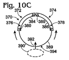
図10と図11は、アンテナ機器に関係する円弧の周りのバリアを含む取調べステーションの上面図を示すが、そこでは、円弧の方向にバリアが移動する。これらの円弧は被検体ポジションの中心に対して同心または偏心にできる。   10 and 11 show a top view of the interrogation station that includes a barrier around an arc related to antenna equipment, where the barrier moves in the direction of the arc. These arcs can be concentric or eccentric with respect to the center of the subject position.

図10A〜図10Cは、それぞれがアンテナ機器376と378を持っている第1と第2のアンテナ機器アセンブリ372と374を備えた取調べステーション370を示す。それぞれのアンテナ機器は相応するように1つ以上のアンテナユニット380、また適切な場合、前の図面を参照しながら述べたように、アンテナアレイ382を含む。特に、機器アセンブリ372と374は、アンテナ機器372と374にそれぞれ関係するそれぞれのバリア384と386を含む。これらのバリアは、関係する円弧387と388を覆うか囲むことができ、それら円弧に沿って電磁放射は上述のようにして送受信される。これらのバリアは、示されたように円弧に従うことができるが、これにかかわらず他の形状も使うことができる。機器アセンブリ372と374は、軌道389によって規定されたような装置経路に沿って移動することができる。   FIGS. 10A-10C show an interrogation station 370 with first and second antenna equipment assemblies 372 and 374, each having antenna equipment 376 and 378. FIG. Each antenna device includes a corresponding one or more antenna units 380 and, where appropriate, an antenna array 382 as described with reference to the previous drawings. In particular, device assemblies 372 and 374 include respective barriers 384 and 386 associated with antenna devices 372 and 374, respectively. These barriers can cover or surround the associated arcs 387 and 388, along which electromagnetic radiation is transmitted and received as described above. These barriers can follow arcs as shown, but other shapes can be used regardless. Instrument assemblies 372 and 374 can move along the device path as defined by track 389.

図面に示したように、被検体390は入口394を通り被検体経路392に沿って取調べステーション370に入ることができる。まず、バリア384と386が経路392に沿った被検体ポジションに対して下流の位置に隣接することができ、取調べステーションからの出口398をブロックすることができる。このバリアは、被検体ポジションに被検体を止め、そしてイメージングの際にそこに留まらせるようにする目的をサポートする。   As shown, the subject 390 can enter the interrogation station 370 along the subject path 392 through the inlet 394. First, barriers 384 and 386 can be adjacent to positions downstream of the subject position along path 392 and block outlet 398 from the interrogation station. This barrier supports the purpose of stopping the subject at the subject position and allowing it to remain there during imaging.

初めに、アンテナ機器376と378は、図10Aに示すように、バリアを開始位置またはブロック位置にした状態で円弧387と388に沿ってイメージングを実行することができる。示されたバリアは、それぞれ約90度の円弧にわたり、それにより、2つのアンテナ機器は被検体ポジションを囲む円筒状のアパーチャの半分をスキャンすることが可能である。円弧の他の長さおよび形状、そしてアンテナ機器アセンブリの他の数を使うことができる。   Initially, the antenna devices 376 and 378 can perform imaging along arcs 387 and 388 with the barrier in the starting or blocking position, as shown in FIG. 10A. The barriers shown each span an approximately 90 degree arc, so that the two antenna instruments can scan half of the cylindrical aperture surrounding the subject position. Other lengths and shapes of arcs and other numbers of antenna equipment assemblies can be used.

被検体の第1の側面をスキャンした後で、アンテナ機器アセンブリは、取調べステーションへの入口394における経路392上の上流ポジションへの軌道389に沿って対向する方向に移動することができる。次に被検体の他の側面がスキャンされ、そして図10Bに示すように、出口が開いた状態で被検体は取調べステーションを出ることが許容されうる。次に、アンテナ機器アセンブリは、出口398において経路392をブロックする、初期位置とは反対の方向に再び軌道389に沿って移動させられ、そして入口394が開いて、第2の被検体390’が取調べステーションに入ることを許容される。   After scanning the first side of the subject, the antenna equipment assembly can move in an opposing direction along a trajectory 389 to an upstream position on the path 392 at the entrance 394 to the interrogation station. The other side of the subject is then scanned, and the subject can be allowed to exit the interrogation station with the outlet open, as shown in FIG. 10B. The antenna equipment assembly is then moved again along the trajectory 389 in a direction opposite to the initial position, blocking the path 392 at the outlet 398, and the inlet 394 is opened so that the second subject 390 ' Allowed to enter the interrogation station.

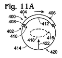
図11A〜図11Dに示した取調べステーション400は、アンテナ機器アセンブリ402の連続的な回転を提供する。アセンブリ402は、約120度の円弧406に沿って延在するアンテナ機器404を持つものとして示されているが、円弧406より長いか、または短い他の円弧の長さを使うことができる。アンテナ機器アセンプリ402はアンテナユニット408を含み、そのアンテナユニットはアンテナアレイ410に含められることができる。バリア412は円弧に沿って延在することができる。アンテナ機器アセンプリは、軌道414で表されるように、ガイドによって規定された経路に沿って移動するように適合されうる。軌道414は、少なくとも部分的に、被検体ポジション416の周りに延在する。   The interrogation station 400 shown in FIGS. 11A-11D provides continuous rotation of the antenna equipment assembly 402. Although the assembly 402 is shown as having an antenna device 404 that extends along an arc 406 of about 120 degrees, other arc lengths that are longer or shorter than the arc 406 can be used. The antenna equipment assembly 402 includes an antenna unit 408 that can be included in the antenna array 410. The barrier 412 can extend along an arc. The antenna equipment assembly can be adapted to move along the path defined by the guide, as represented by the track 414. The trajectory 414 extends at least partially around the subject position 416.

まず、被検体418は、入口420を通ってまた経路422に沿って取調べステーションに入り、被検体ポジションに止まることができる。次に、アンテナ機器404は、図11Aに示すように、バリアを開始位置またはブロック位置にした状態で円弧406に沿ったポジションからイメージングを行なう。バリアは、被検体ポジションから経路422に沿って下流の、取調べステーションからの出口424をブロックすることができる。被検体の第1の側面をスキャンした後で、アンテナ機器アセンプリは、第2のポジションへ軌道414に沿って移動し、図11Bに示すように、始めの位置を補完することができる。そして被検体の画像の次の120度分がスキャンできる。   First, the subject 418 can enter the interrogation station through the inlet 420 and along the path 422 and can stop at the subject position. Next, as shown in FIG. 11A, the antenna device 404 performs imaging from a position along the arc 406 with the barrier at the start position or the block position. The barrier can block the exit 424 from the interrogation station downstream along the path 422 from the subject position. After scanning the first side of the subject, the antenna equipment assembly can move along the trajectory 414 to the second position and complement the starting position, as shown in FIG. 11B. The next 120 degrees of the subject image can be scanned.

次にアセンブリ402は、図11Cに示すように、被検体の最後の120度分のスキャンを行う第3のポジションに移動することができる。取調べステーションからの出口は、アセンプリ402がこの第3のポジションあるときに開き、被検体が取調べステーションを出ることが許容される。次にアンテナ機器アセンブリ402は軌道414に沿って始めの位置に移動することができ、出口424において経路422をブロックすることができる。このポジションにアセンブリがある状態で、入口420が再び遮られることなく、第2の被検体418’が取調べステーションに入ることを許容する。   The assembly 402 can then move to a third position to scan the last 120 degrees of the subject, as shown in FIG. 11C. The exit from the interrogation station opens when assembly 402 is in this third position, allowing the subject to exit the interrogation station. The antenna equipment assembly 402 can then move to an initial position along the track 414 and can block the path 422 at the outlet 424. With the assembly in this position, the second subject 418 'is allowed to enter the interrogation station without the entrance 420 being obstructed again.

図12は、他の図に示した種々の取調ステーションに使うことができる取調べステーション430の特徴を示す。図12は、アンテナユニットの垂直のアレイ434を含み、簡単のために円錐で表したアンテナユニット436、437、438および439を含むアンテナ機器432を簡略化して示す。アレイ434は垂直のフレーム442に沿って取り付けられる。アレイは、全般的に、アレイに一様に平行に延在する被検体ポジション444に向けられる。   FIG. 12 illustrates the characteristics of the interrogation station 430 that can be used for the various interrogation stations shown in the other figures. FIG. 12 shows, in a simplified manner, an antenna device 432 that includes a vertical array 434 of antenna units, including antenna units 436, 437, 438, and 439, which are represented by cones for simplicity. Array 434 is mounted along a vertical frame 442. The array is generally directed to a subject position 444 that extends uniformly parallel to the array.

アレイの低い部分434aでは、アンテナユニット439を含むアンテナユニットはフレーム442に対応するライン446に垂直に一様に延在するように、アレイに対して取り付けられている。アレイの上の部分434bでは、アンテナユニットはアレイのラインに対し鋭角に取り付けられている。例えばアンテナユニット436は、アレイのラインに対して垂線から約30度、またはアレイラインに対し約60度の角A1で取り付けられるように示されている。望ましい被検体の範囲を得るのに適切なように、特定の用途においていかなる適切な角度も使うことができる。アンテナユニット437、438、およびその他のアンテナユニットは、それらがアレイの低い部分434aでのようにアレイに垂直に整列するまでアレイのラインに対して次第に増加する角度にある。この例では、アレイの上の部分434bは、全般的に被検体ポジションのレベルの上に延在する。被検体ポジションは、その被検体ポジションに位置した被検体の、所望の全般的なポジションに対応することができる。従って、すべてのアンテナユニットは被検体ポジションに向けられる。アレイの上の部分434bにおけるアンテナユニットは、被検体ポジションの上から見たイメージングを提供することが可能である。   In the lower portion 434a of the array, the antenna unit, including the antenna unit 439, is attached to the array so as to extend uniformly perpendicular to the line 446 corresponding to the frame 442. In the upper portion 434b of the array, the antenna unit is attached at an acute angle to the line of the array. For example, the antenna unit 436 is shown mounted at an angle A1 of about 30 degrees from the normal to the array line or about 60 degrees to the array line. Any suitable angle can be used in a particular application, as appropriate to obtain the desired analyte range. The antenna units 437, 438, and other antenna units are at progressively increasing angles relative to the lines of the array until they align perpendicular to the array as in the lower portion 434a of the array. In this example, the upper portion 434b of the array generally extends above the level of the subject position. The subject position can correspond to a desired general position of the subject located at the subject position. Accordingly, all antenna units are directed to the subject position. The antenna unit in the upper portion 434b of the array can provide imaging viewed from above the subject position.

図13は、図12に示したアンテナ機器432の変形例の概略正面図を示す。この例では、アレイ434の低い部分434aにおけるアンテナユニットは、アレイのライン446に対して異なる円周方向の向きまたは方位に向けられる。例えば、アンテナユニット439は前方に向けられる。アンテナユニット447と448は、それぞれアンテナユニット439の上と下にあり、図から判るようにそれぞれ左と右に向けることができる。このパターンがアレイに沿って繰り返されうる。アレイの上の部分434bでは、アンテナユニットは、アレイの低い部分のように左方、前方、右方に様々に向けられている。さらに、図12を参照しながら上述したように、アンテナユニットは鋭角に下方に向けることができる。例えば、アンテナユニット436は下方かつ前方を指すことができ、アンテナユニットは(図の視点から見て)下方かつ右方を指すことができ、またアンテナユニット438は下方かつ左方を指すことができる。この例では、アレイのラインに対し鋭角の下方に向けられたアンテナユニットの合計は、アレイの下方への距離が増加するに従って減少する。所与の用途に要求されるイメージング特性の提供に適切なように、アンテナユニットの方向付けに関する他の多くの変形を使用することができる。   FIG. 13 shows a schematic front view of a modification of the antenna device 432 shown in FIG. In this example, the antenna units in the lower portion 434a of the array 434 are oriented in different circumferential orientations or orientations relative to the lines 446 of the array. For example, the antenna unit 439 is directed forward. The antenna units 447 and 448 are respectively above and below the antenna unit 439 and can be directed to the left and right, respectively, as can be seen from the figure. This pattern can be repeated along the array. In the upper portion 434b of the array, the antenna units are variously oriented to the left, front, and right as in the lower portion of the array. Furthermore, as described above with reference to FIG. 12, the antenna unit can be directed downward at an acute angle. For example, the antenna unit 436 can point downward and forward, the antenna unit can point downward and right (from the perspective of the figure), and the antenna unit 438 can point downward and left. . In this example, the sum of the antenna units that are directed acutely downward relative to the lines of the array decreases as the distance down the array increases. Many other variations on the orientation of the antenna unit can be used as appropriate to provide the imaging characteristics required for a given application.

この論議は垂直アンテナアレイに向けられたものだったが、水平アンテナアレイにも当てはまる。例えば、図14は、被検体ポジション454に隣接して置かれたアンテナ機器452を持った他の取調べステーション450の概略平面図を示す。この例では、アンテナ機器は円弧456の形のラインに沿って延在する。アンテナアレイ458は、アンテナユニット460、461、462、463および464を含んだ複数のアンテナユニットを含み、円弧に沿って分布されている。示されたように、円弧456は被検体ポジションの中心468から隔てられた曲率中心466を持つ。円弧の他の形状および曲率を使うこともできる。例えばアレイは、直線470に沿って延在することができ、そして図12に示すようにポジションに対して異なる角度で、だが水平な位置に置かれたアンテナを持つことができる。   This discussion was aimed at vertical antenna arrays, but it also applies to horizontal antenna arrays. For example, FIG. 14 shows a schematic plan view of another interrogation station 450 having an antenna device 452 placed adjacent to a subject position 454. In this example, the antenna device extends along a line in the form of an arc 456. The antenna array 458 includes a plurality of antenna units including antenna units 460, 461, 462, 463, and 464, and is distributed along an arc. As shown, arc 456 has a center of curvature 466 that is separated from center 468 of the subject position. Other shapes and curvatures of the arc can also be used. For example, the array can extend along a straight line 470 and can have antennas placed at different angles to the position but in a horizontal position as shown in FIG.

アレイ458は中間部分458aを含むことができ、その中間部分に沿ってアンテナユニット462のようなアンテナユニットが、この例では円弧456であるアレイのラインに対する法線方向に延在する。アレイは端部458bと458cも含む。これらの端部におけるアンテナユニット460、461、463および464のようなアンテナユニットは、円弧に対して鋭角に取り付けられる。例えばアンテナユニット461は、円弧に対して約80度の補完的な角度に対応して、約10度の角A2で取り付けられている。そして、これらの端部におけるアンテナユニットは、それらがアレイの円弧に垂直に取り付けられる場合よりも一層直接に被検体ポジション454に向かって向けられうる。   The array 458 can include an intermediate portion 458a along which an antenna unit, such as antenna unit 462, extends in a direction normal to the lines of the array, which in this example is an arc 456. The array also includes ends 458b and 458c. Antenna units such as antenna units 460, 461, 463 and 464 at these ends are mounted at an acute angle with respect to the arc. For example, the antenna unit 461 is attached at an angle A2 of about 10 degrees, corresponding to a complementary angle of about 80 degrees with respect to the arc. The antenna units at these ends can then be directed more directly toward the subject position 454 than if they were mounted perpendicular to the arc of the array.

アンテナアレイ458は、円弧456に沿って水平にのみ延在することができ、その場合、アレイに直面する被検体ポジションにおける被検体の側面は、垂直に円弧を機械的移動することによって、完全にスキャンされることができる。状況に応じて、アレイ458は取調べステーション474の2次元のアレイ472の一部とすることができ、そのアレイは図12に示したアレイ434をも含むことができる。例えば、図14におけるアレイの視点(view:視界または視野)は、図12におけるライン13−13に沿って取った視点(視界または視野)とすることができる。アレイ472が十分に大きいならば、電子的に被検体をスキャンすることによってアレイに直面する被検体の側面のイメージを得ることが可能である。いくつかの例では、被検体の一部のみのイメージが必要となると思われるが、そんな場合には、アレイは被検体の一部のみに対応することができる。   The antenna array 458 can only extend horizontally along the arc 456, in which case the side of the subject at the subject position facing the array is completely moved by mechanically moving the arc vertically. Can be scanned. Depending on the circumstances, the array 458 can be part of the two-dimensional array 472 of the interrogation station 474, which can also include the array 434 shown in FIG. For example, the viewpoint (view or field of view) of the array in FIG. 14 may be the viewpoint (view or field of view) taken along line 13-13 in FIG. If the array 472 is large enough, it is possible to obtain an image of the side of the subject facing the array by electronically scanning the subject. In some instances, an image of only a portion of the subject may be required, but in such a case, the array can accommodate only a portion of the subject.

さらに他の形状の取調べステーションの平面図を図15に示す。取調べステーション480は、被検体486に対して配置されるか、または配置されるよう適合された第1と第2のアンテナ機器482と484を含む。アンテナ機器482は、円弧488に沿って電磁放射を送受信するよう適合されたアンテナユニットまたはアンテナユニットのアレイを含むことができる。この例の円弧488は、曲率中心490の周りに第1の端部488aから第2の端部488bまで延在する半円である。同様に、アンテナ機器484は、第1と第2の端部492aと492bを持つ、曲率中心494の周りの半円の円弧492内で延在する。上述のように、バリアをこれらの円弧に関係付けることができ、そして円弧は、被検体のイメージングの際に1つ以上のアンテナユニットの移動または位置に対応することができる。曲率中心490が円弧492の端部492aにあることが判る。同様に、曲率中心494が円弧488の端部488aにある。それで、この特別な構造では、4つの円弧の端部、2つの曲率中心、および被検体ポジションが共通の直線496に沿って整列される。   FIG. 15 is a plan view of an investigation station having another shape. The interrogation station 480 includes first and second antenna devices 482 and 484 that are positioned with respect to the subject 486 or adapted to be positioned. Antenna device 482 can include an antenna unit or an array of antenna units adapted to transmit and receive electromagnetic radiation along arc 488. The arc 488 in this example is a semicircle extending around the center of curvature 490 from the first end 488a to the second end 488b. Similarly, the antenna device 484 extends within a semicircular arc 492 around the center of curvature 494 having first and second ends 492a and 492b. As described above, barriers can be associated with these arcs, and the arcs can correspond to the movement or position of one or more antenna units during imaging of the subject. It can be seen that the center of curvature 490 is at the end 492 a of the arc 492. Similarly, the center of curvature 494 is at the end 488 a of the arc 488. Thus, in this particular structure, the ends of the four arcs, the two centers of curvature, and the subject position are aligned along a common straight line 496.

この形状では、円弧の第1の端部488aと492aが他の端部よりも被検体ポジションに近く置かれる。2つの円弧は、円弧がライン496について非対称の形状を形成するという点で、お互いに対してオフセット(offset)している(ずれている)と考えることができる。それによって円弧は、入口500と出口502を持った被検体経路498の部分的な定義を形成する。アンテナ円弧が被検体経路に最も近く位置しているところに、被検体ポジションが位置している。さらに、被検体が被検体ポジションにあるとき円弧は被検体を囲んでおり、アンテナ機器を移動することなく、または被検体を移動することなく、被検体のすべての側面のイメージングを可能にする。さらに、円弧は入口と出口の間の経路の境界を規定する。他の形状も使うことができる。   In this shape, the first ends 488a and 492a of the arc are placed closer to the subject position than the other ends. The two arcs can be considered offset with respect to each other in that the arcs form an asymmetric shape about line 496. The arc thereby forms a partial definition of the subject path 498 having an entrance 500 and an exit 502. The subject position is located where the antenna arc is located closest to the subject path. Furthermore, when the subject is in the subject position, the arc surrounds the subject, allowing imaging of all sides of the subject without moving the antenna device or moving the subject. Furthermore, the arc defines the path boundary between the inlet and the outlet. Other shapes can also be used.

イメージングシステムは、広く多様な用途で使うことができる。それらは、限定された施設、あるいは、破壊的または敵対の意向を持った人間に関係しそうであると考えられる公共施設の入口におけるような、保安検査が目下なされている従来からの固定された軌跡で使うことができる。このよう設備では、場合によっては連続的な流れとなるような、関係する取調べステーションまたはステーション群を通る人員を取り調べる(interrogate)ために、イメージングシステムを機能的に(作動可能に)しておくことは重要である。   Imaging systems can be used in a wide variety of applications. They are traditional fixed trajectories where security checks are currently underway, such as at the entrances of limited facilities or public facilities that are likely to be related to people with destructive or hostile intentions. Can be used in. In such a facility, the imaging system must be functional (operable) to interrogate personnel through the relevant interrogation station or stations, possibly in a continuous flow. Is important.

イメージングシステムは、固定的または永久的な設備を保証しない特別な用途における、被検体の一時的な取調べにも役立つ。スポーツまたは政治活動のような特別または不定期なイベントを例として含む。他の例は、部隊が大きな領土にわたって動いている軍事行動であり、そしてチェックポイントが非軍人に対する接近ポイントにおいて構築される。これらの用途のために使用するように容易に組み立てられ、次に他の場所において再利用のために分解できるイメージングシステムを持つことは望ましいと思われる。   Imaging systems are also useful for temporary interrogation of subjects in special applications that do not guarantee fixed or permanent equipment. Examples include special or irregular events such as sports or political activities. Another example is a military action where troops are moving over a large territory, and checkpoints are built at the approach points for non-military personnel. It would be desirable to have an imaging system that can be easily assembled for use for these applications and then disassembled for reuse elsewhere.

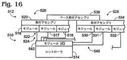
図15〜図19は、イメージングシステムの組み立て、分解、機能向上、および維持管理を容易にできるイメージングシステムの種々の局面を示す。図16はアンテナ機器512とコントローラ514を持つイメージングシステム510の構成図である。イメージングシステム510の機能と構造は、上述のイメージングに対応し、ここで述べる特定の特徴を持つ。   FIGS. 15-19 illustrate various aspects of an imaging system that can facilitate assembly, disassembly, enhancement, and maintenance of the imaging system. FIG. 16 is a configuration diagram of an imaging system 510 having an antenna device 512 and a controller 514. The function and structure of the imaging system 510 corresponds to the imaging described above and has the specific features described herein.

アンテナ機器512は、アレイモジュール516、517および518のような複数のセグメントまたはモジュールを含むことができる。組み合わせにおけるこれらのモジュールはアンテナ機器を形成することができる。フレームまたは取り付けアセンプリ520は、種々のモジュールを、アレイ524の円弧522のような所定の形態で一緒に結合することができる。   Antenna device 512 may include a plurality of segments or modules, such as array modules 516, 517 and 518. These modules in combination can form an antenna device. The frame or mounting assembly 520 can couple the various modules together in a predetermined form, such as the arc 522 of the array 524.

状況に応じて、モジュール516、517および518は、取調べセグメント526のような複数の取調べセグメントの1つを形成することができる。取調べセグメント528のような追加の取調べセグメントは、アレイモジュール530、531および532のような関係するモジュールから形成できる。モジュール530、531および532は、フレームまたは取り付けアセンブリ534によって結合することができる。取調べセグメント526と528、およびその他のものは、アンテナ機器512を形成するために、ベースの取り付けアセンプリ538によって順番に結合できる。   Depending on the circumstances, modules 516, 517, and 518 may form one of a plurality of interrogation segments, such as interrogation segment 526. Additional interrogation segments such as interrogation segment 528 can be formed from related modules such as array modules 530, 531 and 532. Modules 530, 531 and 532 may be coupled by a frame or mounting assembly 534. Interrogation segments 526 and 528, and others, can be coupled in turn by a base mounting assembly 538 to form antenna equipment 512.

リンク540のような通信リンク(通信接続)がそれぞれのモジュールをコントローラ514のモジュール入力/出力デバイス542と接続する。   A communication link (communication connection) such as link 540 connects each module to the module input / output device 542 of the controller 514.

図17は、アンテナ機器512のようなアンテナ機器の、モジュール517のような第2のアレイモジュールと接続される、モジュール516のような第1のアレイモジュールの一形態の全般的な概略図である。モジュール516は、モジュール517の対応するフレーム546に取り付けられるフレーム544を含むことができる。フレーム544と546は、共通のフレームまたは取り付けアセンブリに接続したり、または示されたように、ブラケット554と556のようなアタッチメントアセンプリ552と共にセグメントフレームとしてそれらに結合することによるなど、種々の形態で一緒に取り付けることができる。アレイモジュールを一緒に取り付けるために、他の構造を使うことができる。   FIG. 17 is a general schematic diagram of one form of a first array module, such as module 516, connected to a second array module, such as module 517, of an antenna apparatus, such as antenna apparatus 512. . Module 516 can include a frame 544 that is attached to a corresponding frame 546 of module 517. Frames 544 and 546 can be connected to a common frame or mounting assembly, or as shown, coupled to them as a segment frame with an attachment assembly 552 such as brackets 554 and 556, etc. Can be attached together. Other structures can be used to attach the array modules together.

それぞれのアレイモジュールは、アンテナユニット558、559および560のような複数のアンテナユニットを持つことができる。複数のアレイモジュールが一緒に取り付けられとき、それぞれのアンテナユニットは共同でアンテナアレイ562を形成することができる。それぞれのアンテナユニットはトランシーバ564と通信状態にあり、そのトランシーバはアレイモジュールの一部として存在しうる。すなわち、共通のベースの取り付けアセンブリに取り付けられたり、またはアンテナ機器から遠い場所に存在したりする。そしてトランシーバは、入力/出力データ566などを介して、プロセッサまたは他の信号コントローラデバイスと通信することができる。   Each array module can have a plurality of antenna units, such as antenna units 558, 559 and 560. When multiple array modules are attached together, each antenna unit can jointly form an antenna array 562. Each antenna unit is in communication with transceiver 564, which may be present as part of the array module. That is, it may be attached to a common base mounting assembly or may be remote from the antenna equipment. The transceiver can then communicate with a processor or other signal controller device, such as via input / output data 566.

図18は、円弧568に沿って置かれ、また被検体ポジション570に向けられて、アンテナ機器571を形成するモジュール516、517および518のような、複数のアレイモジュールを示す。この例では、それぞれのアレイモジュールは、モジュール516および517に関係するライン574と576のような直線に沿って配置された複数のアンテナユニット572を持つ。アレイモジュールは、お互いに対し、角A3のようなそれぞれの角度で取り付けることができる。その結果、円弧568は複数の弦から成る。従って、同じアレイモジュールが、直線を含んだいくつかの適切な円弧を形成するように構成でき、その直線に対しては曲率半径が無限遠に及ぶと考えることができる。   FIG. 18 shows a plurality of array modules, such as modules 516, 517, and 518, placed along arc 568 and directed to subject position 570 to form antenna device 571. In this example, each array module has a plurality of antenna units 572 arranged along a straight line such as lines 574 and 576 associated with modules 516 and 517. The array modules can be attached to each other at respective angles, such as angle A3. As a result, the arc 568 is composed of a plurality of strings. Thus, the same array module can be configured to form several suitable arcs that include a straight line, with the radius of curvature extending to infinity for that straight line.

アンテナ機器571を形成するために複数のアレイモジュール516、517および518を使用する取調べステーション580の例を、図19に示す。アレイモジュールは被検体ポジション584の周りに水平に延在するアレイ582を形成する。アレイは、移動機構586によって、被検体ポジションにおける被検体を機械的にスキャンするために上下に移動させられうる。フレーム588は、アンテナ機器の保持をも行うバリアを形成する。トランシーバ590は、被検体のスキャンの際に、アンテナアレイとアンテナユニットの動作を制御することができる。   An example of an interrogation station 580 that uses a plurality of array modules 516, 517, and 518 to form an antenna device 571 is shown in FIG. The array module forms an array 582 that extends horizontally around the subject position 584. The array can be moved up and down by a moving mechanism 586 to mechanically scan the subject at the subject position. The frame 588 forms a barrier that also holds the antenna device. The transceiver 590 can control the operation of the antenna array and the antenna unit when scanning the subject.

状況に応じて、取調べステーション580は、図20に示した取調べステーション594の一部を形成する取調べセグメント592として構成することができる。示されたように、取調べステーション594は、セグメント592、595および596のような複数の取調べセグメントを含むことができる。取調べセグメントは、それぞれの取調べセグメントのアレイによって形成され、結合された円弧602に沿って延在する結合されたアンテナアレイ600を形成するために、セグメントフレーム598上に集合的に取り付けることができる。取調べセグメントのトランシーバ590は、共用のコントローラ604と通信することができる。状況に応じて、取調べセグメントは、別々に取り付けられた単独のトランシーバ、またはイメージングシステム20のコントローラ24を参照しながら前述したように、コントローラ604に含まれるトランシーバを共有することができる。   Depending on the circumstances, the interrogation station 580 can be configured as an interrogation segment 592 that forms part of the interrogation station 594 shown in FIG. As shown, the interrogation station 594 can include multiple interrogation segments such as segments 592, 595 and 596. Interrogation segments can be collectively mounted on the segment frame 598 to form a combined antenna array 600 formed by the respective array of interrogation segments and extending along the combined arc 602. The interrogation segment transceiver 590 can communicate with a shared controller 604. Depending on the situation, the interrogation segment can share a single transceiver that is separately attached or a transceiver included in the controller 604 as described above with reference to the controller 24 of the imaging system 20.

前述のイメージングシステム、取調べステーション、およびアンテナ機器は、さまざまな特性と特徴を持つことが理解されるであろう。種々のこれらの特徴は、種々の組み合わせで使うことができる。例えば、いずれかの取調べステーションを参照しながら述べたアンテナアレイは、アレイセグメントがそれぞれ複数のアレイ、トランシーバを持つ状態で構成することができ、および/または、取調べセグメントとして構成することができる。これらのアレイセグメントと取調べセグメントは、欠陥がある部分をすぐに取り換えることができるので維持管理を容易にし、あるいは必要に応じて全システムを容易に組み立て、または分解することができる。さらに、取調べステーションは、円弧に沿って異なる角度で、あるいは全アンテナ機器、送信または受信アレイに対して垂直または水平に異なる偏波とビーム幅で取り付けられたアンテナユニットを持つことができ、もしくは、アレイ円弧内の個々のアンテナユニットは、円弧とは異なるが共同して円弧を形成するラインに沿って延在するグループまたはセグメントで形成されたアンテナユニットから形成できる。アレイセグメントは、アレイの垂線とは異なるアレイのラインに沿って方向付けることができる。それにより種々の組み合わせと形態が可能である。   It will be appreciated that the aforementioned imaging system, interrogation station, and antenna equipment have various characteristics and features. Various of these features can be used in various combinations. For example, an antenna array described with reference to any interrogation station can be configured with each array segment having multiple arrays, transceivers, and / or can be configured as an interrogation segment. These array segments and interrogation segments can be easily replaced because they can be replaced immediately, or the entire system can be easily assembled or disassembled as needed. In addition, the interrogation station can have antenna units mounted at different angles along the arc, or with different polarizations and beam widths perpendicularly or horizontally to the entire antenna equipment, transmit or receive array, or Individual antenna units within the array arc can be formed from antenna units formed of groups or segments that extend along lines that are different from the arc but jointly form the arc. The array segments can be oriented along a line of the array that is different from the normal of the array. Thereby, various combinations and forms are possible.

記述された種々の取調べステーションのいくつかを持ったイメージングシステムのいくつかの実施形態は、24から30GHz範囲の周波数のFMCW変調を組み込んだ送信信号を使うことができ、そしてFCCの無許可動作要件(FCC unlicensed operation requirements)を満たし、いくつかの限定された合衆国政府周波数帯域(US Government frequency bands)の外にある信号内容を持つことできる。パルス長は2から10マイクロ秒の範囲とすることができる。アンテナビーム幅は、イメージ形成信号プロセッサ要求に依存して、広いビーム実装のために20から120度、狭いビーム幅用途のために1から30度の範囲とすることができる。種々の系統的偏波を使うことができる。同一偏波、直交偏波、楕円偏波、右旋回偏波、および/または、左旋回偏波を例として含む。   Some embodiments of imaging systems with some of the various interrogation stations described can use transmit signals incorporating FMCW modulation with frequencies in the range of 24 to 30 GHz, and FCC unauthorized operating requirements (FCC unlicensed operation requirements) can be met and have signal content outside some limited US Government frequency bands. The pulse length can range from 2 to 10 microseconds. The antenna beam width can range from 20 to 120 degrees for wide beam implementations and 1 to 30 degrees for narrow beam width applications, depending on imaging signal processor requirements. Various systematic polarizations can be used. Examples include the same polarization, orthogonal polarization, elliptical polarization, right-turn polarization, and / or left-turn polarization.

以上のように、添付の特許請求の範囲で規定された発明を、とりわけ、前述の望ましい実施形態を参照しながら提示しかつ説明してきたが、当業者ならば、本発明の精神と範囲から逸脱することなく、多くの変形をこの中に成すことができる、ということを理解するであろう。特徴、機能、要素、および/または特性の他の組み合わせ、および下位の組み合わせは、この適用または関係する適用における現在の請求項の補正または新しい請求項の表現を通して請求しうる。そのような補正された請求項または新しい請求項も、異なる組み合わせに向けられるか、同じ組み合わせに向けられるかにかかわらず、また元の請求項と異なっているか、より広いか、より狭いか、あるいは等しいかどうかにかかわらず、現在の開示の主題のうちに含まれると見なされる。前述の実施形態は例示であり、そしていかなる単独の特徴または要素も、この用途または後の用途において請求されうるすべての可能な組み合わせに対して不可欠であるということはない。請求項が「ある」または「第1の」要素、あるいはその同等物を記載する状況では、このような請求項は1つまたはそれ以上のそのような要素を含み、2つまたはそれ以上のそのような要素を要求することも除外することもしない、ということが理解されるべきである。さらに、第1、第2、または第3などの要素の識別のための主要な指示語は要素間の区別のために使用されており、そのような要素の必要な数または限定された数を指すものではなく、そのような要素の特定の場所または順序を一般的に指しているのでもない。   Thus, while the invention as defined in the appended claims has been presented and described, particularly with reference to the foregoing preferred embodiments, those skilled in the art will depart from the spirit and scope of the present invention. It will be understood that many variations can be made in this without. Other combinations and sub-combinations of features, functions, elements and / or properties may be claimed through amendments of the current claim or the expression of a new claim in this or related application. Such amended or new claim, whether directed to a different combination or the same combination, is different from the original claim, is wider, narrower, or Regardless of whether they are equal, they are considered to be included within the presently disclosed subject matter. The foregoing embodiments are exemplary and no single feature or element is essential to all possible combinations that may be claimed in this or a later application. In the situation where a claim describes “an” or “first” element, or equivalent thereof, such claim includes one or more such elements and includes two or more of those elements It should be understood that no such element is required or excluded. In addition, key directives for identifying elements such as first, second, or third are used to distinguish between elements, and the required or limited number of such elements It does not refer to, nor does it generally refer to a particular location or order of such elements.

説明したイメージングシステムおよびイメージングシステムの構成要素、さらにはそれらにかかわる方法は、監視、計量、および被検体イメージを利用する他の産業に利用することができる。   The described imaging system and components of the imaging system, as well as the methods involved, can be utilized in monitoring, metering, and other industries that utilize subject images.

活性なイメージングシステムを示す全般的な図である。1 is a general diagram illustrating an active imaging system. FIG. イメージングシステムで使うことができる取調べステーションの一般的な例を示す図である。FIG. 2 is a diagram illustrating a general example of an interrogation station that can be used in an imaging system. 様々な取調べステーションの簡略化した上面図である。FIG. 3 is a simplified top view of various interrogation stations. 様々な取調べステーションの簡略化した上面図である。FIG. 3 is a simplified top view of various interrogation stations. 様々な取調べステーションの簡略化した上面図である。FIG. 3 is a simplified top view of various interrogation stations. 様々な取調べステーションの簡略化した上面図である。FIG. 3 is a simplified top view of various interrogation stations. 様々な取調べステーションの簡略化した上面図である。FIG. 3 is a simplified top view of various interrogation stations. 様々な取調べステーションの簡略化した上面図である。FIG. 3 is a simplified top view of various interrogation stations. 様々な取調べステーションの簡略化した上面図である。FIG. 3 is a simplified top view of various interrogation stations. 他の取調べステーションの一連の操作を示す上面図である。It is a top view which shows a series of operation of another investigation station. 他の取調べステーションの一連の操作を示す上面図である。It is a top view which shows a series of operation of another investigation station. 他の取調べステーションの一連の操作を示す上面図である。It is a top view which shows a series of operation of another investigation station. さらに他の取調べステーションの一連の操作を示す上面図である。It is a top view which shows a series of operation of the other investigation station. さらに他の取調べステーションの一連の操作を示す上面図である。It is a top view which shows a series of operation of the other investigation station. さらに他の取調べステーションの一連の操作を示す上面図である。It is a top view which shows a series of operation of the other investigation station. さらに他の取調べステーションの一連の操作を示す上面図である。It is a top view which shows a series of operation of the other investigation station. 取調べステーションの典型的なアンテナアレイ形状を示す側面図である。It is a side view which shows the typical antenna array shape of an investigation station. 図12に示すアンテナアレイの任意選択による実施形態の正面図である。FIG. 13 is a front view of an optional embodiment of the antenna array shown in FIG. 取調べステーションの他の典型的なアンテナアレイ形状であって、図12に示したものと同様の取調べステーションとできるものの平面図である。FIG. 13 is a plan view of another exemplary antenna array shape for an interrogation station that can be an interrogation station similar to that shown in FIG. 横方向にオフセットしたアンテナアレイアセンブリを持った取調べステーションの平面図である。FIG. 6 is a plan view of an interrogation station with a laterally offset antenna array assembly. 複数のアンテナ機器セグメントを有する取調べステーションを持ったイメージングシステムを示す全般的な図である。1 is a general diagram illustrating an imaging system having an interrogation station having multiple antenna equipment segments. FIG. 図16の取調べステーションにおいて有用なアンテナ機器セグメントの一例を示す全般的な図である。FIG. 17 is a general diagram illustrating an example of an antenna equipment segment useful in the interrogation station of FIG. アンテナアレイを形成するのに使うことができる複数のアンテナアレイセグメントの平面図である。FIG. 3 is a plan view of a plurality of antenna array segments that can be used to form an antenna array. アンテナ機器セグメントの一例の等角図である。FIG. 3 is an isometric view of an example antenna equipment segment. 複数のアンテナ機器セグメントを持つ取調べステーションの平面図である。FIG. 6 is a plan view of an interrogation station having a plurality of antenna equipment segments.

符号の説明Explanation of symbols

20 イメージングシステム
22 アンテナ機器
22’ 第2のアンテナ機器
24 コントローラ
26 電磁放射
28 被検体
30 電磁放射
32 移動機構
38 トランシーバ
40 プロセッサ
44 取調べステーション
46 スキャン信号
48 受信信号
50 画像データ
52 出力装置
60 取調べステーション
62 アンテナ機器アセンプリ
64 アンテナ経路移動アセンプリ
66 アンテナ機器
80 取調べステーション
82 アンテナ機器
84 被検体ポジション
86 被検体中心
88 軌跡
90 円弧
92 曲率中心
94 アンテナユニット
96 経路
98 アンテナアレイ
100 被検体
102 水平アレイ
104 アンテナユニット
112 アレイ
114 アパーチャ
116 円
120、122 軸
130 取調べステーション
132 アンテナ機器
134 被検体ポジション
136 被検体中心
138 軌跡
140 円弧
142 曲率中心
144 アンテナユニット
146 経路
148 アンテナアレイ
150 被検体
152 水平アレイ
154 アンテナユニット
158 2次元のアレイ
160 アパーチャ
166、168 軸
170 取調べステーション
172 アンテナユニット
174 アンテナ機器
176 円弧
178 曲率中心
180 被検体中心
182 被検体ポジション
184 アンテナアレイ
186 ビーム
188 旋回軸
192 アンテナユニット
196 円弧
198 アンテナユニット
210 取調べステーション
212 旋回軸
214 アンテナユニット
216 アンテナ機器
218 被検体ポジション
220 被検体中心
222 曲率中心
224 円弧
226 ビーム
230 移動機構
232 アーム
232a 端部
238 駆動機構
242 アンテナユニット
246 アンテナアレイ
248 円弧
250 アンテナユニット
254 アンテナアレイ
260 取調べステーション
262 アンテナ機器
266 アンテナユニット
268 アンテナアレイ
270 ビーム
272 旋回軸
274、276 被検体ポジション
280 取調べステーション
282 アンテナ機器
290 被検体ポジション
292 被検体中心
294 アンテナユニット
302 旋回軸
310 ビーム
330 取調べステーション
332、334 アンテナ機器
336 被検体ポジション
338 被検体中心
340 アンテナユニット
342 アンテナアレイ
344 円弧
344a 中間部分
344b、344c、344d、344e 端部
346、350 曲率中心
353 円弧
370 取調べステーション
372、376 アンテナ機器
380 アンテナユニット
382 アンテナアレイ
384 バリア
387 円弧
389 軌道
390 被検体
390’ 第2の被検体
392 経路
400 取調べステーション
402 アンテナ機器アセンブリ
404 アンテナ機器
406 円弧
408 アンテナユニット
410 アンテナアレイ
412 バリア
414 軌道
416 被検体ポジション
418 被検体
418’ 第2の被検体
422 経路
430 取調べステーション
432 アンテナ機器
434 アレイ
436、437、438、439 アンテナユニット
442 フレーム
444 被検体ポジション
447 アンテナユニット
450 取調べステーション
452 アンテナ機器
454 被検体ポジション
456 円弧
458 アンテナアレイ
458a 中間部分
458b 端部
460、461、462 アンテナユニット
466 曲率中心
472 アレイ
474 取調べステーション
480 取調べステーション
482、484 アンテナ機器
486 被検体
488 円弧
488a 端部
490 曲率中心
492 円弧
492a 端部
494 曲率中心
510 イメージングシステム
512 アンテナ機器
514 コントローラ
516 アレイモジュール
517 モジュール
520 アセンプリ
522 円弧
524 アレイ
526、528 セグメント
530 アレイモジュール
534 アセンブリ
538 アセンプリ
542 モジュール入力/出力デバイス
552 アタッチメントアセンプリ
558 アンテナユニット
562 アンテナアレイ
564 トランシーバ
568 円弧
570 被検体ポジション
571 アンテナ機器
572 アンテナユニット
580 取調べステーション
582 アレイ
584 被検体ポジション
586 移動機構
590 トランシーバ
592 セグメント
594 取調べステーション
598 セグメントフレーム
600 アンテナアレイ
602 円弧
604 コントローラ
DESCRIPTION OF SYMBOLS 20 Imaging system 22 Antenna apparatus 22 '2nd antenna apparatus 24 Controller 26 Electromagnetic radiation 28 Subject 30 Electromagnetic radiation 32 Moving mechanism 38 Transceiver 40 Processor 44 Interrogation station 46 Scan signal 48 Received signal 50 Image data 52 Output device 60 Interrogation station 62 Antenna equipment assembly 64 Antenna path moving assembly 66 Antenna equipment 80 Interrogation station 82 Antenna equipment 84 Subject position 86 Subject center 88 Trajectory 90 Arc 92 Center of curvature 94 Antenna unit 96 Route 98 Antenna array 100 Subject 102 Horizontal array 104 Antenna unit 112 Array 114 Aperture 116 Circle 120, 122 Axis 130 Interrogation station 132 Antenna equipment 34 Object position 136 Object center 138 Trajectory 140 Arc 142 Center of curvature 144 Antenna unit 146 Path 148 Antenna array 150 Subject 152 Horizontal array 154 Antenna unit 158 Two-dimensional array 160 Aperture 166, 168 Axis 170 Interrogation station 172 Antenna unit 174 Antenna equipment 176 Arc 178 Center of curvature 180 Subject center 182 Subject position 184 Antenna array 186 Beam 188 Swivel axis 192 Antenna unit 196 Arc 198 Antenna unit 210 Interrogation station 212 Swivel axis 214 Antenna unit 216 Antenna equipment 218 Subject position 220 Subject Center 222 Center of curvature 224 Arc 226 Beam 230 Moving mechanism 23 Arm 232a End 238 Drive mechanism 242 Antenna unit 246 Antenna array 248 Arc 250 Antenna unit 254 Antenna array 260 Interrogation station 262 Antenna equipment 266 Antenna unit 268 Antenna array 270 Beam 272 Swivel axis 274, 276 Subject position 280 Interrogation station 282 Antenna equipment 290 Subject position 292 Subject center 294 Antenna unit 302 Rotating axis 310 Beam 330 Interrogation station 332, 334 Antenna equipment 336 Subject position 338 Subject center 340 Antenna unit 342 Antenna array 344 Arc 344a Intermediate part 344b, 344c, 344d, 344e End 346, 350 Center of curvature 353 Arc 70 Interrogation Station 372, 376 Antenna Equipment 380 Antenna Unit 382 Antenna Array 384 Barrier 387 Arc 389 Trajectory 390 Subject 390 ′ Second Subject 392 Path 400 Interrogation Station 402 Antenna Equipment Assembly 404 Antenna Equipment 406 Arc 408 Antenna Unit 410 Antenna Array 412 Barrier 414 Trajectory 416 Subject position 418 Subject 418 ′ Second subject 422 Path 430 Interrogation station 432 Antenna equipment 434 Array 436, 437, 438, 439 Antenna unit 442 Frame 444 Subject position 447 Antenna unit 450 Interrogation station 452 Antenna equipment 454 Subject position 456 Arc 458 Antenna array 458a Middle portion 458b End 460, 461, 462 Antenna unit 466 Center of curvature 472 Array 474 Interrogation station 480 Interrogation station 482, 484 Antenna equipment 486 Subject 488 Arc 488a End 490 Curvature center 492 Arc center 492a End of curvature 492a End of curvature 492a System 512 Antenna equipment 514 Controller 516 Array module 517 Module 520 Assembly 522 Arc 524 Array 526 528 Segment 530 Array module 534 Assembly 538 Assembly 542 Module input / output device 552 Attachment assembly 558 Antenna unit 562 Antenna array 564 Transceiver 568 Transceiver 568 Specimen position 571 antenna device 572 antenna unit 580 interrogation station 582 array 584 subject position 586 moving mechanism 590 transceiver 592 segments 594 interrogation station 598 segments frame 600 Antenna array 602 arc 604 Controller

Claims (113)

被検体ポジション(84)から隔てられ、被検体ポジション(84)の中心(86)から隔てられた曲率中心(92)を持った少なくとも1つの第1の湾曲したポイントの軌跡(88)を含む第1のポイントの軌跡(88)に沿って分布されたポジションから、約200MHzから約1THzまでの周波数範囲の電磁放射(26,30)を、中心(86)を持つ被検体ポジション(84)における被検体(100)に向かって送信しそこから受信するように構成されたアンテナ機器(82)と、
アンテナ機器(82)を操作し、受信した放射(30)を表現する出力(48)を作り出すように構成されたトランシーバ(38)と、
トランシーバ出力(48)を、被検体(100)の少なくとも一部のイメージを表現する画像データ(50)に変換するように適合されたプロセッサ(40)と、
を有することを特徴とするイメージングシステム(20)。
A first trajectory (88) including at least one first curved point trajectory (88) spaced from the subject position (84) and having a center of curvature (92) from the center (86) of the subject position (84). Electromagnetic radiation (26, 30) in the frequency range from about 200 MHz to about 1 THz from the position distributed along the trajectory (88) of the point 1 is measured at the subject position (84) having the center (86). An antenna device (82) configured to transmit to and receive from the specimen (100);
A transceiver (38) configured to operate the antenna equipment (82) and produce an output (48) representing the received radiation (30);
A processor (40) adapted to convert the transceiver output (48) into image data (50) representing an image of at least a portion of the subject (100);
An imaging system (20) comprising:
被検体ポジション(84)の中心(86)は、湾曲したポイントの軌跡(88)の曲率中心(92)と、関係するポイントの軌跡(88)の間にあることを特徴とする請求項1に記載のシステム(20)。   The center (86) of the subject position (84) is between the center of curvature (92) of the locus (88) of the curved point and the locus (88) of the relevant point. The system (20) described. アンテナ機器(82)は、湾曲したポイントの軌跡(88)に沿って湾曲した経路(96)内を移動するように適合されることを特徴とする請求項2に記載のシステム(20)。   The system (20) of claim 2, wherein the antenna device (82) is adapted to move in a curved path (96) along a locus of curved points (88). アンテナ機器(82)は、湾曲したポイントの軌跡(88)に沿って延在することを特徴とする請求項3に記載のシステム(20)。   The system (20) of claim 3, wherein the antenna device (82) extends along a curved point trajectory (88). 被検体ポジション(84)の中心(86)に対して偏心形状(118)を持つ被検体(100)に関する使用のためのシステムであって、ポイントの軌跡(88)が、湾曲したポイントの軌跡(88)に直面する被検体(100)の形状(118)に対応する曲線(90)を持つことを特徴とする請求項4に記載のシステム(20)。   A system for use with a subject (100) having an eccentric shape (118) relative to the center (86) of the subject position (84), wherein the point trajectory (88) is a curved point trajectory ( The system (20) according to claim 4, characterized in that it has a curve (90) corresponding to the shape (118) of the subject (100) facing (88). 被検体ポジション(84)の中心(86)に対して偏心形状(118)を持つ被検体(100)に関する使用のためのシステムであって、ポイントの軌跡(88)が、湾曲したポイントの軌跡(88)に直面する被検体(100)の形状(118)に対応する湾曲ライン(90)を持つことを特徴とする請求項3に記載のシステム(20)。   A system for use with a subject (100) having an eccentric shape (118) relative to the center (86) of the subject position (84), wherein the point trajectory (88) is a curved point trajectory ( The system (20) according to claim 3, characterized in that it has a curved line (90) corresponding to the shape (118) of the subject (100) facing the surface (88). 湾曲したポイントの軌跡(344)に沿った経路(96)が、複数の異なる曲率中心(346,348,350,352)を持つことを特徴とする請求項3に記載のシステム(20)。   The system (20) of claim 3, wherein the path (96) along the curved point trajectory (344) has a plurality of different centers of curvature (346, 348, 350, 352). アンテナ機器(82)が、湾曲したポイントの軌跡(88)に沿って延在することを特徴とする請求項2に記載のシステム(20)。   The system (20) of claim 2, wherein the antenna device (82) extends along a curved point trajectory (88). 被検体ポジション(84)の中心(86)に対して偏心形状(118)を持つ被検体(100)に関する使用のためのシステムであって、ポイントの軌跡(88)が、湾曲したポイントの軌跡(88)に隣接する被検体(100)の形状(118)に対応する湾曲ライン(90)を持つことを特徴とする請求項8に記載のシステム(20)。   A system for use with a subject (100) having an eccentric shape (118) relative to the center (86) of the subject position (84), wherein the point trajectory (88) is a curved point trajectory ( The system (20) according to claim 8, characterized in that it has a curved line (90) corresponding to the shape (118) of the subject (100) adjacent to 88). 湾曲したポイントの軌跡(344)に沿った経路(96)が、複数の異なる曲率中心(346,348)を持つことを特徴とする請求項8に記載のシステム(20)。   The system (20) of claim 8, wherein the path (96) along the locus of curved points (344) has a plurality of different centers of curvature (346, 348). 湾曲したポイントの軌跡が、対向する端部(488a,488b)を持つ第1の円弧(488)を規定し、被検体ポジション(486)は、他方の端部(488b)よりも円弧(488)の一方の端部(488a)に近いことを特徴とする請求項2に記載のシステム(20)。   The locus of the curved point defines a first arc (488) having opposite ends (488a, 488b), and the subject position (486) has an arc (488) more than the other end (488b). 3. System (20) according to claim 2, characterized in that it is close to one end (488a) of the. 被検体ポジション(486)は、一般に、湾曲したポイントの軌跡の曲率中心(490)と、円弧(488)の一方の端部(488a)との間にあることを特徴とする請求項11に記載のシステム(20)。   12. The subject position (486) is generally between the center of curvature (490) of the locus of the curved point and one end (488a) of the arc (488). System (20). アンテナ機器(482,484)は、さらに、第1のポイントの軌跡から隔てられた第2のポイントの軌跡に沿って分布された電磁放射(26,30)を送受信するように構成され、第2のポイントの軌跡は、曲率中心(494)と対向する端部(492a,492b)を持つ第2の円弧(492)を形成する第2の湾曲したポイントの軌跡を含み、そして被検体ポジション(486)は、第2の円弧(492)の他方の端部(492b)よりも第2の円弧(492)の一方の端部(492a)に近いことを特徴とする請求項11に記載のシステム(20)。   The antenna device (482, 484) is further configured to transmit and receive electromagnetic radiation (26, 30) distributed along a second point trajectory separated from the first point trajectory, and the second The point trajectory includes a second curved point trajectory forming a second arc (492) having ends (492a, 492b) opposite the center of curvature (494) and the subject position (486). ) Is closer to one end (492a) of the second arc (492) than to the other end (492b) of the second arc (492). 20). 被検体ポジション(486)は、第1と第2の円弧(488,492)の間にあることを特徴とする請求項13に記載のシステム(20)。   The system (20) of claim 13, wherein the subject position (486) is between the first and second arcs (488, 492). 第1の円弧(488)の一方の端部(488a)と第2の円弧(492)の一方の端部(492a)を結ぶラインは、目標物ポジション(486)を通過することを特徴とする請求項14に記載のシステム(20)。   A line connecting one end (488a) of the first arc (488) and one end (492a) of the second arc (492) passes through the target position (486). The system (20) of claim 14. 第1と第2の円弧(488,492)は、全般的に、S形状をした被検体通路(498)を形成することを特徴とする請求項13に記載のシステム(20)。   The system (20) of claim 13, wherein the first and second arcs (488, 492) generally form an S-shaped subject passage (498). 湾曲したポイントの軌跡(138)の曲率中心(142)とアンテナ機器(132)は、被検体ポジション(134)の中心(136)と同じ側にあることを特徴とする請求項1に記載のシステム(20)。   The system of claim 1, wherein the center of curvature (142) of the locus of curved points (138) and the antenna device (132) are on the same side as the center (136) of the subject position (134). (20). 湾曲したポイントの軌跡(138)の曲率中心(138)は被検体ポジション(134)の中心(136)とアンテナ機器(132)との間にあることを特徴とする請求項17に記載のシステム(20)。   18. System (18) according to claim 17, characterized in that the center of curvature (138) of the locus (138) of the curved point is between the center (136) of the subject position (134) and the antenna device (132). 20). アンテナ機器(132)は、湾曲したポイントの軌跡(138)に沿って湾曲した経路(146)内を移動するように適合されることを特徴とする請求項18に記載のシステム(20)。   19. The system (20) of claim 18, wherein the antenna device (132) is adapted to move in a curved path (146) along a curved point trajectory (138). アンテナ機器(132)は、湾曲したポイントの軌跡(138)に沿って延在することを特徴とする請求項19に記載のシステム(20)。   20. The system (20) of claim 19, wherein the antenna device (132) extends along a curved point trajectory (138). 被検体ポジション(134)の中心(136)に対して偏心形状を持つ被検体(150)に関する使用のためのシステムであって、ポイントの軌跡(138)が、湾曲したポイントの軌跡(138)に直面する被検体(150)の形状に対応する曲線を持つことを特徴とする請求項20に記載のシステム(20)。   A system for use with a subject (150) having an eccentric shape with respect to the center (136) of the subject position (134), wherein the point trajectory (138) becomes a curved point trajectory (138). 21. System (20) according to claim 20, characterized in that it has a curve corresponding to the shape of the subject (150) facing. アンテナ機器(332,334)は、第1の湾曲したポイントの軌跡を規定する第1の円弧(344)内を移動する第1のアンテナアレイ(342)と、第2の湾曲したポイントの軌跡を規定する第2の円弧(344)内を移動する第2のアンテナアレイ(342)とを含み、第1と第2の円弧(344)は、被検体ポジション(336)の中心(338)とそれぞれのアンテナアレイ(342)との間に置かれたそれぞれの曲率中心(346,348)をもつことを特徴とする請求項19に記載のシステム(20)。   The antenna device (332, 334) includes a first antenna array (342) that moves in a first arc (344) that defines a trajectory of the first curved point, and a trajectory of the second curved point. A second antenna array (342) that moves within a second arc (344) that defines, wherein the first and second arcs (344) are respectively the center (338) of the subject position (336). 20. System (20) according to claim 19, characterized in that each has a center of curvature (346, 348) placed between the antenna array (342). 末端ポジション(360)と基部ポジション(358)との間で第1のアンテナアレイ(342)を移動するように適合されたアレイ機器移動機構(355)をさらに有し、前記アレイ(342)は、末端ポジション(360)における時よりも基部ポジション(358)における時に、より被検体ポジション(336)に近いことを特徴とする請求項22に記載のシステム(20)。   The system further comprises an array instrument moving mechanism (355) adapted to move the first antenna array (342) between a distal position (360) and a base position (358), the array (342) comprising: 23. The system (20) of claim 22, wherein the system (20) is closer to the subject position (336) when in the base position (358) than when in the distal position (360). 被検体ポジション(134)の中心(136)に対して偏心形状を持つ被検体(150)に関する使用のためのシステムであって、ポイントの軌跡(138)が、湾曲したポイントの軌跡(138)に直面する被検体(150)の形状に対応する湾曲ライン(140)を持つことを特徴とする請求項19に記載のシステム(20)。   A system for use with a subject (150) having an eccentric shape with respect to the center (136) of the subject position (134), wherein the point trajectory (138) becomes a curved point trajectory (138). 20. System (20) according to claim 19, characterized in that it has a curved line (140) corresponding to the shape of the subject (150) facing. アンテナ機器(132)は、湾曲したポイントの軌跡(138)に沿って延在することを特徴とする請求項18に記載のシステム(20)。   19. The system (20) of claim 18, wherein the antenna device (132) extends along a curved point trajectory (138). アンテナ機器(332,334)は、第1の湾曲したポイントの軌跡を規定する第1の円弧(344a)内を移動する第1のアンテナアレイ(342)と、第2の湾曲したポイントの軌跡を規定する第2の円弧(344a)内を移動する第2のアンテナアレイ(342)とを含み、第1と第2の円弧(344a)は、被検体ポジション(336)の中心(338)とそれぞれのアンテナアレイ(342)との間に置かれたそれぞれの曲率中心(346,348)をもつことを特徴とする請求項25に記載のシステム(20)。   The antenna device (332, 334) includes a first antenna array (342) that moves within a first arc (344a) that defines a locus of the first curved point, and a locus of the second curved point. A second antenna array (342) that moves within a second arc (344a) that defines the first and second arcs (344a) and a center (338) of the subject position (336), respectively. 26. The system (20) of claim 25, having a respective center of curvature (346, 348) placed between the antenna array (342). 末端ポジション(360)と基部ポジション(358)との間で第1のアンテナアレイ(342)を移動するように適合されたアレイ機器移動機構(355)をさらに有し、前記アレイ(342)は、末端ポジション(360)における時よりも基部ポジション(358)における時に、より被検体ポジション(336)に近いことを特徴とする請求項26に記載のシステム(20)。   The system further comprises an array instrument moving mechanism (355) adapted to move the first antenna array (342) between a distal position (360) and a base position (358), the array (342) comprising: 27. The system (20) of claim 26, wherein the system (20) is closer to the subject position (336) when in the base position (358) than when in the distal position (360). 被検体ポジション(134)の中心(136)に対して偏心形状を持つ被検体(150)に関する使用のためのシステムであって、ポイントの軌跡(138)が、湾曲したポイントの軌跡(138)に直面する被検体(150)の形状に対応する湾曲ライン(140)を持つことを特徴とする請求項25に記載のシステム(20)。   A system for use with a subject (150) having an eccentric shape with respect to the center (136) of the subject position (134), wherein the point trajectory (138) becomes a curved point trajectory (138). 26. System (20) according to claim 25, characterized in that it has a curved line (140) corresponding to the shape of the subject (150) facing. アンテナ機器(174)は少なくとも1つのアンテナユニット(172)を含み、それぞれのアンテナユニット(172)は、湾曲したポイントの軌跡(176)の曲率中心(178)から隔てられた旋回軸(188)の周りに旋回し、それによって、それぞれのアンテナユニット(172)は、旋回軸(188)の周りにアンテナユニット(172)が旋回するのに従って、被検体ポジション(182)の少なくとも一部を横切ってスキャンすることを特徴とする請求項25に記載のシステム(20)。   The antenna device (174) includes at least one antenna unit (172), each antenna unit (172) having a pivot axis (188) separated from the center of curvature (178) of the curved point locus (176). Swiveling around, whereby each antenna unit (172) scans across at least a portion of the subject position (182) as the antenna unit (172) swivels about the swiveling axis (188) 26. The system (20) of claim 25, wherein: アンテナ機器(174)は少なくとも1つのアンテナユニット(172)含み、それぞれのアンテナユニット(172)は、湾曲したポイントの軌跡(176)の曲率中心(178)から隔てられた旋回軸(188)の周りに旋回し、それによって、それぞれのアンテナユニット(172)は、旋回軸(188)の周りにアンテナユニット(172)が旋回するのに従って、被検体ポジション(182)の少なくとも一部を横切ってスキャンすることを特徴とする請求項18に記載のシステム(20)。   The antenna device (174) includes at least one antenna unit (172), each antenna unit (172) around a pivot axis (188) separated from a center of curvature (178) of a curved point locus (176). So that each antenna unit (172) scans across at least a portion of the subject position (182) as the antenna unit (172) pivots about the pivot axis (188). The system (20) according to claim 18, characterized in that: それぞれのアンテナユニット(172)は、固定された旋回軸(188)の周りに旋回することを特徴とする請求項30に記載のシステム(20)。   The system (20) of claim 30, wherein each antenna unit (172) pivots about a fixed pivot axis (188). ポイントの軌跡は複数の曲率中心を持つことを特徴とする請求項18に記載のシステム(20)。   19. The system (20) of claim 18, wherein the point trajectory has a plurality of centers of curvature. アンテナ機器(216)は、被検体ポジション(218)の中心(220)と湾曲したポイントの軌跡(224)の曲率中心(222)との間にあることを特徴とする請求項17に記載のシステム(20)。   18. System according to claim 17, characterized in that the antenna device (216) is between the center (220) of the subject position (218) and the center of curvature (222) of the curved point locus (224). (20). アンテナ機器(216)は少なくとも1つのアンテナユニット(214)含み、それぞれのアンテナユニット(214)は、湾曲したポイントの軌跡(224)の曲率中心(224)と一致する旋回軸(212)の周りに旋回し、それによって、それぞれのアンテナユニット(214)は、旋回軸(212)の周りにアンテナユニット(214)が旋回するのに従って、被検体ポジション(218)の少なくとも一部を横切ってスキャンすることを特徴とする請求項33に記載のシステム(20)。   The antenna device (216) includes at least one antenna unit (214), each antenna unit (214) around a pivot axis (212) that coincides with the center of curvature (224) of the locus (224) of the curved point. Swivel, whereby each antenna unit (214) scans across at least a portion of the subject position (218) as the antenna unit (214) swivels about the swivel axis (212) 34. The system (20) according to claim 33, characterized by: それぞれのアンテナユニット(214)は、固定された旋回軸(212)の周りに旋回することを特徴とする請求項34に記載のシステム(20)。   The system (20) according to claim 34, wherein each antenna unit (214) pivots about a fixed pivot axis (212). ポイントの軌跡(344)は複数の異なる曲率中心(346,348,350,352)を持つことを特徴とする請求項33に記載のシステム(20)。   34. The system (20) of claim 33, wherein the point trajectory (344) has a plurality of different centers of curvature (346, 348, 350, 352). 被検体ポジション(218)から見た時、湾曲したポイントの軌跡(224)は凸状であることを特徴とする請求項33に記載のシステム(20)。   34. System (20) according to claim 33, characterized in that the locus (224) of the curved point is convex when viewed from the object position (218). アンテナ機器(262)は少なくとも1つのアンテナユニット(266)含み、それぞれのアンテナユニット(266)は、アンテナユニット(266)を実質的に通過する旋回軸(272)の周りに旋回し、それによって、それぞれのアンテナユニット(266)は、旋回軸(272)の周りにアンテナユニット(266)が旋回するのに従って、被検体ポジション(274)の少なくとも一部を横切ってスキャンすることを特徴とする請求項17に記載のシステム(20)。   The antenna device (262) includes at least one antenna unit (266), each antenna unit (266) pivoting about a pivot axis (272) substantially passing through the antenna unit (266), thereby Each antenna unit (266) scans across at least a portion of a subject position (274) as the antenna unit (266) pivots about a pivot axis (272). 18. System (20) according to 17. それぞれのアンテナユニット(266)は、固定された旋回軸(272)の周りに旋回することを特徴とする請求項40に記載のシステム(20)。   41. The system (20) according to claim 40, wherein each antenna unit (266) pivots about a fixed pivot axis (272). ポイントの軌跡(344)は複数の異なる曲率中心(346,348,350,352)を持つことを特徴とする請求項1に記載のシステム(20)。   The system (20) of claim 1, wherein the point trajectory (344) has a plurality of different centers of curvature (346, 348, 350, 352). ポイントの軌跡(353,354)は、中間湾曲部分と、その中間湾曲部分の両端にある端部湾曲部分とを、中間湾曲部分が端部の曲率半径より大きな曲率半径を持った状態で持っていることを特徴とする請求項40に記載のシステム(20)。   The locus of points (353, 354) has an intermediate curved portion and end curved portions at both ends of the intermediate curved portion with the intermediate curved portion having a radius of curvature larger than the radius of curvature of the end portion. 41. The system (20) according to claim 40, characterized in that: 被検体ポジション(336)の中心(338)に対して偏心形状を持つ被検体に関する使用のためのシステムであって、ポイントの軌跡が、湾曲したポイントの軌跡(344)に直面する被検体の形状に対応する湾曲ライン(344a,344b,344c)を持つことを特徴とする請求項41に記載のシステム(20)。   A system for use with a subject having an eccentric shape with respect to the center (338) of the subject position (336), wherein the shape of the subject whose point trajectory faces a curved point trajectory (344) 42. System (20) according to claim 41, characterized in that it has curved lines (344a, 344b, 344c) corresponding to. ポイントの軌跡は、中間湾曲部分(344a)と、その中間湾曲部分(344a)の両端において、中間湾曲部分(344a)に対して被検体ポジション(336)の中心(338)に向かって曲げられた端部(344d,344e)とを持っていることを特徴とする請求項40に記載のシステム(20)。   The locus of the point is bent toward the center (338) of the subject position (336) with respect to the intermediate curved portion (344a) at both ends of the intermediate curved portion (344a) and the intermediate curved portion (344a). 41. System (20) according to claim 40, characterized in that it has ends (344d, 344e). 端部(344d、344e)は直線であることを特徴とする請求項43に記載のシステム(20)。   44. System (20) according to claim 43, characterized in that the ends (344d, 344e) are straight. 端部(344b,344c)は、中間湾曲部分(344a)が端部(344b,344c)の曲率半径より短い曲率半径を持つ状態で、曲げられることを特徴とする請求項43に記載のシステム(20)。   44. System (44) according to claim 43, characterized in that the ends (344b, 344c) are bent with the intermediate curved portion (344a) having a radius of curvature shorter than the radius of curvature of the ends (344b, 344c). 20). 被検体ポジション(336)の中心(338)に対して偏心形状を持つ被検体に関する使用のためのシステムであって、中間湾曲部分(344a)および端部(344b,344c)が、中間湾曲部分および端部(344a,344b,344c)に直面する被検体の形状に対応した結合形状を持っていることを特徴とする請求項43に記載のシステム(20)。   A system for use with a subject having an eccentric shape relative to a center (338) of a subject position (336), wherein the intermediate curved portion (344a) and the end portions (344b, 344c) 44. System (20) according to claim 43, characterized in that it has a binding shape corresponding to the shape of the subject facing the end (344a, 344b, 344c). 被検体ポジション(486)から隔てられ、曲率中心(490)を持ちかつ対向する端部(488a,488b)を備えた第1の円弧(488)を規定する少なくとも1つの第1の湾曲したポイントの軌跡を含む第1のポイントの軌跡に沿って分布されたポジションから、約200MHzから約1THzまでの周波数範囲の電磁放射(26,30)を、被検体ポジション(486)が円弧の他方の端部(488b)よりも円弧の一方の端部(488a)に近い状態で、被検体ポジション(486)における被検体に向かって送信しそこから受信するように構成されたアンテナ機器(482)と、
アンテナ機器(482)を操作し、受信した放射(30)を表現する出力(48)を作り出すように構成されたトランシーバ(38)と、
トランシーバ(38)出力を、被検体の少なくとも一部のイメージを表現する画像データ(50)に変換するように適合されたプロセッサ(40)と、
を有することを特徴とするイメージングシステム(20)。
At least one first curved point defining a first arc (488) spaced from the subject position (486), having a center of curvature (490) and having opposite ends (488a, 488b); Electromagnetic radiation (26, 30) in the frequency range from about 200 MHz to about 1 THz from the position distributed along the locus of the first point including the locus, and the subject position (486) at the other end of the arc An antenna device (482) configured to transmit to and receive from the subject at the subject position (486) in a state closer to one end (488a) of the arc than (488b);
A transceiver (38) configured to operate an antenna device (482) to produce an output (48) representing the received radiation (30);
A processor (40) adapted to convert the output of the transceiver (38) into image data (50) representing an image of at least a portion of the subject;
An imaging system (20) comprising:
被検体ポジション(486)は、一般に、湾曲したポイントの軌跡の曲率中心(490)と、円弧(488)の一方の端部(488a)との間にあることを特徴とする請求項47に記載のシステム(20)。   The object position (486) is generally between the center of curvature (490) of the locus of the curved point and one end (488a) of the arc (488). System (20). アンテナ機器(482)は、さらに、第1のポイントの軌跡から隔てられた第2のポイントの軌跡に沿って分布された電磁放射(26,30)を送受信するように構成され、第2のポイントの軌跡は、曲率中心(494)と対向する端部(492a,492b)を持つ第2の円弧(492)を形成する第2の湾曲したポイントの軌跡を含み、そして被検体ポジション(486)は、第2の円弧(492)の他方の端部(492b)よりも第2の円弧(492)の一方の端部(492a)に近いことを特徴とする請求項48に記載のシステム(20)。   The antenna device (482) is further configured to transmit and receive electromagnetic radiation (26, 30) distributed along a second point trajectory separated from the first point trajectory, the second point Trajectory includes a second curved point trajectory forming a second arc (492) having ends (492a, 492b) opposite the center of curvature (494), and the subject position (486) is 49. System (20) according to claim 48, characterized in that it is closer to one end (492a) of the second arc (492) than to the other end (492b) of the second arc (492). . 被検体ポジション(486)は、第1と第2の円弧(488,492)の間にあることを特徴とする請求項49に記載のシステム(20)。   The system (20) of claim 49, wherein the subject position (486) is between the first and second arcs (488, 492). 第1の円弧(488)の一方の端部(488a)と第2の円弧(492)の一方の端部(492a)を結ぶライン(496)は、物体ポジション(486)を通過することを特徴とする請求項50に記載のシステム(20)。   A line (496) connecting one end (488a) of the first arc (488) and one end (492a) of the second arc (492) passes through the object position (486). 51. The system (20) of claim 50. 前記ライン(496)は、第1の円弧(488)の他方の端部(488b)と第2の円弧(492)の他方の端部(492b)をも通過することを特徴とする請求項51に記載のシステム(20)。   52. The line (496) also passes through the other end (488b) of the first arc (488) and the other end (492b) of the second arc (492). (20). 第1と第2の円弧(488、492)のそれぞれの一方の端部(488a,492a)は、第1と第2の円弧(488,492)の他方の中心(490,494)に隣接することを特徴とする請求項51に記載のシステム(20)。   One end (488a, 492a) of each of the first and second arcs (488, 492) is adjacent to the other center (490, 494) of the first and second arcs (488, 492). 52. The system (20) of claim 51, wherein: 被検体ポジション(444)から隔てられ、少なくとも1つのライン(446)に沿ってアレイ(434)の状態で分布されたポジションから、約200MHzから約1THzまでの周波数範囲の電磁放射(26,30)を、被検体ポジション(444)における被検体に向かって送信しそこから受信するように構成されたアンテナユニット(436,437,438,439)であって、それぞれのアンテナユニット(436,437,438,439)が、アレイ(434)のライン(446)に対して固定された角度に向けられており、少なくとも1つのアンテナユニット(436,437,438,439)がアレイ(434)のライン(446)に対して鋭角に向けられているアンテナユニット(436,437,438,439)と、
アンテナユニット(436,437,438,439)のアレイ(434)を操作し、受信した放射(30)を表現する出力(48)を作り出すように構成されたトランシーバ(38)と、
トランシーバ出力(48)を、被検体の少なくとも一部のイメージを表現する画像データ(50)に変換するように適合されたプロセッサ(40)と、
を有することを特徴とするイメージングシステム(20)。
Electromagnetic radiation (26, 30) in a frequency range from about 200 MHz to about 1 THz from positions distributed in an array (434) along at least one line (446), separated from the subject position (444) Are transmitted to the subject at the subject position (444) and received from the antenna unit (436, 437, 438, 439), and each antenna unit (436, 437, 438). , 439) are oriented at a fixed angle with respect to the line (446) of the array (434), and at least one antenna unit (436, 437, 438, 439) is oriented to the line (446) of the array (434). ) Antenna units (436, 437, 438, 439) oriented at an acute angle to And,
A transceiver (38) configured to operate an array (434) of antenna units (436, 437, 438, 439) to produce an output (48) representing the received radiation (30);
A processor (40) adapted to convert the transceiver output (48) into image data (50) representing an image of at least a portion of the subject;
An imaging system (20) comprising:
アレイ(434)のライン(446)は直線であることを特徴とする請求項54に記載のシステム(20)。   55. The system (20) of claim 54, wherein the line (446) of the array (434) is a straight line. アレイ(458)のライン(456)は少なくとも部分的に湾曲していることを特徴とする請求項54に記載のシステム(20)。   55. The system (20) of claim 54, wherein the lines (456) of the array (458) are at least partially curved. アレイ(458)のライン(456)は、被検体ポジション(454)から隔てられた曲率中心(466)を持つ円弧(456)を含み、円弧(456)に沿って配置された複数のアンテナユニット(460,461,462,463,464)は、円弧(456)に対して鋭角に向けられていることを特徴とする請求項56に記載のシステム(20)。   The line (456) of the array (458) includes an arc (456) having a center of curvature (466) separated from the subject position (454), and a plurality of antenna units arranged along the arc (456) ( 57. System (20) according to claim 56, characterized in that 460, 461, 462, 463, 464) are oriented at an acute angle with respect to the arc (456). 円弧(456)に沿って配置されたアンテナユニット(460,461,462,463,464)は、全般的に、被検体ポジション(454)に向けられていることを特徴とする請求項57に記載のシステム。   58. Antenna unit (460, 461, 462, 463, 464) arranged along an arc (456) is generally directed to the subject position (454). System. アンテナユニット(460,461,462,463,464)の角度はアレイ(458)の長さに沿って変化することを特徴とする請求項54に記載のシステム。   55. The system of claim 54, wherein the angle of the antenna units (460, 461, 462, 463, 464) varies along the length of the array (458). 少なくとも一部のアンテナユニット(460,461,462,463,464)は、全般的に、被検体ポジション(454)に向けられていることを特徴とする請求項54に記載のシステム。   55. The system of claim 54, wherein at least some antenna units (460, 461, 462, 463, 464) are generally directed to a subject position (454). アレイ(472)は二次元であることを特徴とする請求項54に記載のシステム。   55. The system of claim 54, wherein the array (472) is two dimensional. アレイ(472)は平面状であることを特徴とする請求項61に記載のシステム。   62. The system of claim 61, wherein the array (472) is planar. アレイ(472)は湾曲したライン(456)に沿った少なくとも1つの方向に延在することを特徴とする請求項61に記載のシステム。   62. The system of claim 61, wherein the array (472) extends in at least one direction along the curved line (456). アンテナユニット(436,437,438)の角度はアレイ(434)の長さに沿って変化することを特徴とする請求項63に記載のシステム。   64. The system of claim 63, wherein the angle of the antenna units (436, 437, 438) varies along the length of the array (434). 被検体ポジション(444)から隔てられ、少なくとも1つのライン(446)に沿ってアレイ(434)の状態で分布されたポジションから、約200MHzから約1THzまでの周波数範囲の電磁放射(26,30)を、被検体ポジション(444)における被検体に向かって送信しそこから受信するように構成されたアンテナユニット(436,437,438,439)であって、それぞれのアンテナユニット(436,437,438,439)が、アレイ(434)のライン(446)上で所与の方向を有しており、少なくとも2つのアンテナユニット(436,437,438,439)がアレイ(434)のライン(446)上で異なる方向を有しているアンテナユニット(436,437,438,439)と、
アンテナユニット(436,437,438,439)のアレイ(434)を操作し、受信した放射(30)を表現する出力(48)を作り出すように構成されたトランシーバ(38)と、
トランシーバ(38)出力を、被検体の少なくとも一部のイメージを表現する画像データ(50)に変換するように適合されたプロセッサ(40)と、
を有することを特徴とするイメージングシステム(20)。
Electromagnetic radiation (26, 30) in a frequency range from about 200 MHz to about 1 THz from positions distributed in an array (434) along at least one line (446), separated from the subject position (444) Are transmitted to the subject at the subject position (444) and received from the antenna unit (436, 437, 438, 439), and each antenna unit (436, 437, 438). , 439) has a given direction on line (446) of array (434), and at least two antenna units (436, 437, 438, 439) are on line (446) of array (434). Antenna units (436, 437, 438, 439) having different directions on the top,
A transceiver (38) configured to operate an array (434) of antenna units (436, 437, 438, 439) to produce an output (48) representing the received radiation (30);
A processor (40) adapted to convert the output of the transceiver (38) into image data (50) representing an image of at least a portion of the subject;
An imaging system (20) comprising:
少なくとも2つのアンテナユニット(436,437,438,439,447,448)が、アレイ(434)のライン(446)上で異なる円周方向の向きを持つことを特徴とする請求項65に記載のシステム(20)。   66. The at least two antenna units (436, 437, 438, 439, 447, 448) have different circumferential orientations on the line (446) of the array (434). System (20). 少なくとも2つのアンテナユニット(436,437,438)の少なくとも1つが、アレイ(434)のライン(446)に対して鋭角に向けられてもいることを特徴とする請求項66に記載のシステム(20)。   67. System (20) according to claim 66, characterized in that at least one of the at least two antenna units (436, 437, 438) is also oriented at an acute angle with respect to the line (446) of the array (434). ). 少なくとも2つのアンテナユニット(436,437,438)の少なくとも1つが、アレイ(434)のライン(446)に対して鋭角に向けられてもいることを特徴とする請求項65に記載のシステム(20)。   66. System (20) according to claim 65, characterized in that at least one of the at least two antenna units (436, 437, 438) is also oriented at an acute angle with respect to the line (446) of the array (434). ). 被検体ポジション(336)から隔てられ、第1のポイントの軌跡(344a)に沿って分布されたポジションから、約200MHzから約1THzまでの周波数範囲の電磁放射(26,30)を、被検体ポジション(336)における被検体に向かって送信しそこから受信するように構成されたアンテナ機器(66,334)と、
第1のアンテナ経路(70)に沿ってアンテナ機器(66,334)を移動するように適合された第1の移動機構(68,355)と、
第1の経路ポジション(360)と第2の経路ポジション(358)の間で第1のアンテナ経路(70)を横切る方向に第1のアンテナ経路(70)を移動する方法で、第1の移動機構(68,355)とアンテナ機器(66)とを移動するように適合された第2の移動機構(74)と、
アンテナ経路が第2の経路ポジション(358)にある時に、アンテナ機器(66,334)を操作し、被検体の少なくとも一部のイメージを表現する画像データ(50)を作り出すように構成されたコントローラ(24)と、
を有することを特徴とするイメージングシステム(20)。
Electromagnetic radiation (26, 30) in a frequency range from about 200 MHz to about 1 THz from a position distributed along the trajectory (344a) of the first point separated from the object position (336). Antenna devices (66, 334) configured to transmit to and receive from the subject in (336);
A first moving mechanism (68, 355) adapted to move the antenna device (66, 334) along the first antenna path (70);
The first movement is achieved by moving the first antenna path (70) in a direction across the first antenna path (70) between the first path position (360) and the second path position (358). A second moving mechanism (74) adapted to move the mechanism (68, 355) and the antenna device (66);
A controller configured to operate the antenna device (66, 334) and generate image data (50) representing an image of at least a portion of the subject when the antenna path is in the second path position (358). (24)
An imaging system (20) comprising:
被検体ポジション(336)から隔てられ、第1のポイントの軌跡(344a)から隔てられた第2のポイントの軌跡(344a)に沿って分布されたポジションから、約200MHzから約1THzまでの周波数範囲の電磁放射(26,30)を、中心(338)を持つ被検体ポジション(336)における被検体に向かって送信しそこから受信するように構成され第2のアンテナ機器(332)と、第2のアンテナ機器(332)に対して、第1の移動機構(60,355)と第1のアンテナ機器(66,334)を移動する第2の移動機構(74)と、第2のアンテナ機器(332)を操作するように構成されたコントローラ(24)と、をさらに有することを特徴とする請求項69に記載のシステム(20)。   A frequency range from about 200 MHz to about 1 THz from a position distributed along the second point trajectory (344a) separated from the subject position (336) and from the first point trajectory (344a). A second antenna device (332) configured to transmit to and receive from the subject at a subject position (336) having a center (338). The second moving mechanism (74) for moving the first moving mechanism (60, 355) and the first antenna device (66, 334) with respect to the antenna device (332) of the second antenna device (332) 70. The system (20) of claim 69, further comprising a controller (24) configured to operate 332). 第2のアンテナ経路(344a)に沿って第2のアンテナ機器(332)を移動するように適合された第3の移動機構(68)をさらに有することを特徴とする請求項70に記載のシステム(20)。   71. The system of claim 70, further comprising a third moving mechanism (68) adapted to move the second antenna device (332) along the second antenna path (344a). (20). 第1と第2のアンテナ経路(344a)が、被検体ポジション(336)の対向する側面上にあることを特徴とする請求項71に記載のシステム(20)。   72. The system (20) of claim 71, wherein the first and second antenna paths (344a) are on opposite sides of the subject position (336). 被検体ポジション(416)から隔てられ、第1のポイントの軌跡に沿って分布されたポジションから、約200MHzから約1THzまでの周波数範囲の電磁放射(26,30)を、被検体ポジション(416)における被検体(418)に向かって送信しそこから受信するように構成されたアンテナ機器(404)と、
第1のアンテナ経路(70)に沿ってアンテナ機器(404)を移動するように適合された第1の移動機構(68)と、
第1のアンテナ経路(70)を横切る方向に第1のアンテナ経路(70)を移動する方法で、第1の移動機構(68,355)とアンテナ機器(66)とを移動するように適合された第2の移動機構(74)と、
被検体ポジション(416)の周りの連続したループ(414)中でアンテナ経路(70)を移動する方法で、第1の移動機構(68)とアンテナ機器(404)を移動するように適合された第2の移動機構(74)と、
アンテナ経路(70)がループ(404)の周りの異なるポジションにある時に、アンテナ機器(404)を操作し、また第1と第2の移動機構(68,74)を操作し、被検体(418)の少なくとも一部のイメージを表現する画像データ(50)を作り出すように構成されたコントローラ(24)と、
を有することを特徴とするイメージングシステム(20)。
Electromagnetic radiation (26, 30) in the frequency range from about 200 MHz to about 1 THz from the position separated from the subject position (416) and distributed along the locus of the first point is subject position (416). An antenna device (404) configured to transmit to and receive from the subject (418) at
A first moving mechanism (68) adapted to move the antenna device (404) along a first antenna path (70);
Adapted to move the first moving mechanism (68, 355) and the antenna device (66) in a manner that moves the first antenna path (70) in a direction across the first antenna path (70). A second moving mechanism (74);
Adapted to move the first moving mechanism (68) and the antenna device (404) in a manner that moves the antenna path (70) in a continuous loop (414) around the subject position (416). A second moving mechanism (74);
When the antenna path (70) is at different positions around the loop (404), the antenna device (404) is operated, the first and second moving mechanisms (68, 74) are operated, and the subject (418) is operated. A controller (24) configured to produce image data (50) representing at least a portion of the image of
An imaging system (20) comprising:
被検体(418)は人間であり、システム(20)は被検体ポジション(416)を通過する連続的な被検体経路(422)と第1のアンテナ経路(70)に沿って延在するバリア(412)とを含み、第2の移動機構(74)は、アンテナ機器(404)と第1の移動機構(68)と共にバリア(412)を移動するように適合され、コントローラ(24)は、さらに、アンテナ機器(404)の操作を始める前に、被検体ポジション(416)から下流の被検体経路(422)上にバリア(412)を置き、またアンテナ機器(404)の操作を始めた後に、被検体ポジション(416)から下流の被検体経路(422)から離してバリア(412)を置く第2の移動機構(74)を操作するように構成されることを特徴とする請求項73に記載のシステム(20)。   The subject (418) is a human, and the system (20) has a continuous subject path (422) passing through the subject position (416) and a barrier extending along the first antenna path (70) ( 412), and the second moving mechanism (74) is adapted to move the barrier (412) with the antenna device (404) and the first moving mechanism (68), the controller (24) further Before starting the operation of the antenna device (404), after placing the barrier (412) on the subject path (422) downstream from the subject position (416) and starting the operation of the antenna device (404), The second moving mechanism (74) configured to place the barrier (412) away from the subject path (422) downstream from the subject position (416) is configured to be operated. The system according to (20). 被検体ポジション(396)から隔てられたポジションから、約200MHzから約1THzまでの周波数範囲の電磁放射(26,30)を、被検体ポジション(396)における被検体(390)に向かって送信しそこから受信するように構成されたアンテナ機器(376,378)と、
第1のアンテナ経路(387)に沿ってアンテナ機器(376)を移動するように適合された第1の移動機構(68)と、
第1のアンテナ経路(387)から隔てられた第2のアンテナ経路(388)に沿って第2のアンテナ機器(378)を移動するように適合された第2の移動機構(68)と、
第1の移動機構(68)と第1のアンテナ機器(376)とを被検体ポジション(396)の周りの第1の方向に移動するように適合され、第2の移動機構(68)と第2のアンテナ機器(378)とを被検体ポジション(396)の周りの第1の方向とは反対の第2の方向に移動するように適合された第3の移動機構(74)と、
アンテナ機器(376,378)が被検体ポジション(396)の周りの異なるポジションにある時に、アンテナ機器(376,378)を操作し、また第1と第2の移動機構(68)を操作し、被検体(390)の少なくとも一部のイメージを表現する画像データ(50)を作り出すように構成されたコントローラ(24)と、
を有することを特徴とするイメージングシステム(20)。
From a position separated from the subject position (396), electromagnetic radiation (26, 30) in a frequency range from about 200 MHz to about 1 THz is transmitted toward the subject (390) in the subject position (396) and there. An antenna device (376, 378) configured to receive from;
A first moving mechanism (68) adapted to move the antenna device (376) along a first antenna path (387);
A second moving mechanism (68) adapted to move the second antenna device (378) along a second antenna path (388) separated from the first antenna path (387);
The first moving mechanism (68) and the first antenna device (376) are adapted to move in a first direction around the subject position (396), and the second moving mechanism (68) and the first moving mechanism (68) A third movement mechanism (74) adapted to move the second antenna device (378) in a second direction opposite to the first direction about the subject position (396);
When the antenna device (376, 378) is at different positions around the subject position (396), the antenna device (376, 378) is operated, and the first and second moving mechanisms (68) are operated, A controller (24) configured to generate image data (50) representing at least a portion of an image of the subject (390);
An imaging system (20) comprising:
コントローラ(24)は、第1と第2のアンテナ機器(376,378)がお互いに隣接する第1のアンテナポジションと、第1のアンテナポジションから隔てられた第2のアンテナポジションとの間で第1と第2のアンテナ機器(376,378)を移動する第3の移動機構(74)を操作するように構成されることを特徴とする請求項75に記載のシステム。   The controller (24) includes a first antenna position between the first antenna position (376, 378) adjacent to each other and a second antenna position separated from the first antenna position. 76. The system of claim 75, configured to operate a third moving mechanism (74) that moves the first and second antenna devices (376, 378). 第1と第2のアンテナ機器(376,378)は、第2のアンテナポジションにおいてお互いに隣接もしていることを特徴とする請求項76に記載のシステム(20)。   77. The system (20) of claim 76, wherein the first and second antenna devices (376, 378) are also adjacent to each other at the second antenna position. 被検体(390)は人間であり、システム(20)は被検体ポジション(396)を通過する連続的な被検体経路(392)と第1のアンテナ経路(387)に沿って延在する第1のバリア(384)と第2のアンテナ経路(388)に沿って延在する第2のバリア(386)とを含み、第1と第2のバリア(384,386)は、第1のアンテナポジションにおいて被検体ポジション(396)から下流の被検体経路(392)上でお互いに隣接し、かつ第2のアンテナポジションにおいて被検体ポジション(396)から上流の被検体経路(392)上でお互いに隣接することを特徴とする請求項77に記載のシステム(20)。   The subject (390) is a human and the system (20) is a first subject extending along a continuous subject path (392) and a first antenna path (387) passing through the subject position (396). And a second barrier (386) extending along a second antenna path (388), wherein the first and second barriers (384, 386) are at a first antenna position. Adjacent to each other on the object path (392) downstream from the object position (396) and adjacent to each other on the object path (392) upstream from the object position (396) at the second antenna position. 78. The system (20) of claim 77, wherein: 被検体ポジション(84)から隔てられ、被検体ポジション(84)の中心(86)から隔てられた曲率中心(92)を持った少なくとも1つの第1の湾曲したポイントの軌跡(88)を含む第1のポイントの軌跡(88)に沿って分布されたポジションから、約200MHzから約1THzまでの周波数範囲の電磁放射(26)を、中心(86)を持つ被検体ポジション(84)における被検体に向かって送信する段階と、
反射した電磁放射(30)を被検体から受信する段階と、
受信した放射(30)を表現する出力(48)を作り出す段階と、
出力(48)を、被検体の少なくとも一部のイメージを表現する画像データ(50)に変換する段階と、
を有することを特徴とするイメージング方法。
A first trajectory (88) including at least one first curved point trajectory (88) spaced from the subject position (84) and having a center of curvature (92) from the center (86) of the subject position (84). Electromagnetic radiation (26) in the frequency range from about 200 MHz to about 1 THz from the position distributed along the locus of one point (88) to the subject at the subject position (84) having the center (86). Sending to
Receiving reflected electromagnetic radiation (30) from the subject;
Creating an output (48) representing the received radiation (30);
Converting the output (48) into image data (50) representing at least a partial image of the subject;
An imaging method comprising:
請求項79に記載の方法であって、放射(26)を送信する段階はアンテナ機器(82)からの放射(26)を送信する段階を含み、放射(30)を受信する段階はアンテナ機器(82)において放射(30)を受信する段階を含み、さらに前記方法は、湾曲したポイントの軌跡(88)に沿って湾曲した経路(96)内でアンテナ機器(82)を移動する段階を含むことを特徴とする方法。   80. The method of claim 79, wherein transmitting radiation (26) comprises transmitting radiation (26) from antenna equipment (82), and receiving radiation (30) comprises antenna equipment ( Receiving radiation (30) at 82), and further comprising moving the antenna device (82) in a curved path (96) along a locus (88) of curved points. A method characterized by. アンテナ機器(82)を移動する段階は、アンテナ機器(82)から見て被検体ポジション(84)の中心(86)の反対側の曲率中心(92)を持った湾曲したポイントの軌跡(88)に沿ってアンテナ機器(82)を移動する段階を含むことを特徴とする請求項80に記載の方法。   The stage of moving the antenna device (82) consists of a curved point locus (88) having a center of curvature (92) opposite to the center (86) of the subject position (84) when viewed from the antenna device (82). 81. The method of claim 80, comprising moving the antenna device (82) along the line. アンテナ機器(82)を移動する段階は、被検体ポジション(84)の中心(86)に対して偏心した被検体(100)の形状(118)に対応する湾曲したポイントの軌跡(88)に沿ってアンテナ機器(82)を移動する段階を含むことを特徴とする請求項80に記載の方法。   The stage of moving the antenna device (82) is along a curved point trajectory (88) corresponding to the shape (118) of the subject (100) eccentric with respect to the center (86) of the subject position (84). The method of claim 80, comprising moving the antenna device (82). アンテナ機器(332)を移動する段階は、複数の曲率中心(346,348)を複数の持つ湾曲したポイントの軌跡(344)に沿ってアンテナ機器(332)を移動する段階を含むことを特徴とする請求項80に記載の方法。   The step of moving the antenna device (332) includes the step of moving the antenna device (332) along a locus (344) of a curved point having a plurality of centers of curvature (346, 348). 81. The method of claim 80. アンテナ機器(332)を移動する段階は、複数の異なる曲率中心(346,348,350,352)を持つ湾曲したポイントの軌跡(344)に沿ってアンテナ機器(332)を移動する段階を含むことを特徴とする請求項83に記載の方法。   Moving the antenna device (332) includes moving the antenna device (332) along a curved point trajectory (344) having a plurality of different centers of curvature (346, 348, 350, 352). 84. The method of claim 83, wherein: 請求項79に記載の方法であって、湾曲したポイントの軌跡は、対向する端部(488a,488b)を持つ第1の円弧(488)を規定し、さらに前記方法は、他方の端部(488b)よりも円弧(488)の一方の端部(488a)に近く被検体ポジション(486)を置く段階を有することを特徴とする方法。   80. The method of claim 79, wherein the trajectory of the curved point defines a first arc (488) having opposing ends (488a, 488b), and further comprising the other end ( Placing the subject position (486) closer to one end (488a) of the arc (488) than 488b). 放射(26)を送信する段階は、第1のポイントの軌跡から隔てられた第2のポイントの軌跡に沿って分布されたポジションから放射(26)を送信する段階を含み、前記第2のポイントの軌跡は曲率中心(494)と対向する端部(492a,492b)とを持つ第2の円弧(492)を形成する第2の湾曲したポイントの軌跡を含み、被検体ポジション(486)を置く段階は、第2の円弧(492)の他方の端部(492b)よりも第2の円弧(492)の一方の端部(492a)に近く被検体ポジション(486)を置く段階を含むことを特徴とする請求項85に記載の方法。   Transmitting radiation (26) includes transmitting radiation (26) from positions distributed along a second point trajectory separated from a first point trajectory, said second point Includes a locus of a second curved point forming a second arc (492) having a center of curvature (494) and opposite ends (492a, 492b), and places the subject position (486). The step includes placing the subject position (486) closer to one end (492a) of the second arc (492) than to the other end (492b) of the second arc (492). 86. The method of claim 85, characterized in that アンテナ機器(132)を移動する段階は、被検体ポジション(134)の中心(136)のアンテナ機器(132)と同じ側に曲率中心(142)を持つ湾曲したポイントの軌跡(138)に沿ってアンテナ機器(132)を移動する段階を含むことを特徴とする請求項80に記載の方法。   The stage of moving the antenna device (132) is along a locus (138) of a curved point having a center of curvature (142) on the same side as the antenna device (132) of the center (136) of the subject position (134). 81. The method of claim 80, comprising moving the antenna equipment (132). アンテナ機器(132)を移動する段階は、被検体ポジション(134)の中心(136)とアンテナ機器(132)との間に曲率中心(138)を持つ湾曲したポイントの軌跡(138)に沿ってアンテナ機器(132)を移動する段階を含むことを特徴とする請求項87に記載の方法。   The stage of moving the antenna device (132) is along a locus (138) of a curved point having a center of curvature (138) between the center (136) of the subject position (134) and the antenna device (132). 88. The method of claim 87, comprising moving the antenna equipment (132). アンテナ機器(332,334)は第1のアンテナアレイ(342)と第2のアンテナアレイ(342)を含み、アンテナ機器(332,334)を移動する段階は、第1の円弧(344)内で第1のアンテナアレイ(342)を移動する段階と、第2の円弧(344)内で第2のアンテナアレイ(342)を移動する段階とを含み、第1と第2の円弧(344)は、被検体ポジション(336)の中心(338)とそれぞれのアンテナアレイ(342)との間に置かれたそれぞれの曲率中心(346,348)を持つことを特徴とする請求項88に記載の方法。   The antenna device (332, 334) includes a first antenna array (342) and a second antenna array (342), and moving the antenna device (332, 334) is within the first arc (344). Moving the first antenna array (342) and moving the second antenna array (342) within the second arc (344), wherein the first and second arcs (344) include: 89. The method of claim 88, comprising a respective center of curvature (346, 348) placed between the center (338) of the subject position (336) and the respective antenna array (342). . 末端ポジション(360)と基部ポジション(358)との間で第1のアンテナアレイ(342)を移動する段階をさらに有し、アレイ(342)は、末端ポジション(360)における時よりも基部ポジション(358)における時に、より被検体ポジション(336)に近いことを特徴とする請求項89に記載の方法。   The method further comprises moving the first antenna array (342) between a distal position (360) and a base position (358), wherein the array (342) is more proximal than at the distal position (360). 90. The method of claim 89, wherein the method is closer to the subject position (336) at 358). アンテナ機器(332,334)は第1のアンテナアレイ(342)と第2のアンテナアレイ(342)を含み、アンテナ機器(332,334)を移動する段階は、第1の円弧(344)内で第1のアンテナアレイ(342)を移動する段階と、第2の円弧(344)内で第2のアンテナアレイ(342)を移動する段階とを含み、第1と第2の円弧(344)は、被検体ポジション(336)の中心(338)とそれぞれのアンテナアレイ(342)との間に置かれたそれぞれの曲率中心(346,348)を持つことを特徴とする請求項87に記載の方法。   The antenna device (332, 334) includes a first antenna array (342) and a second antenna array (342), and moving the antenna device (332, 334) is within the first arc (344). Moving the first antenna array (342) and moving the second antenna array (342) within the second arc (344), wherein the first and second arcs (344) include: 88. Method according to claim 87, characterized in that each center of curvature (346, 348) is placed between the center (338) of the subject position (336) and the respective antenna array (342). . 末端ポジション(360)と基部ポジション(358)との間で第1のアンテナアレイ(342)を移動する段階をさらに有し、アレイ(342)は、末端ポジション(360)における時よりも基部ポジション(358)における時に、より被検体ポジション(336)に近いことを特徴とする請求項91に記載の方法。   The method further comprises moving the first antenna array (342) between a distal position (360) and a base position (358), wherein the array (342) is more proximal than at the distal position (360). 92. The method of claim 91, wherein the method is closer to the subject position (336) at 358). アンテナ機器(216)は少なくとも1つのアンテナユニット(214)含み、アンテナ機器(216)を移動する段階は、湾曲したポイントの軌跡(224)の曲率中心(224)に対応する旋回軸(212)の周りにそれぞれのアンテナユニット(214)を旋回させる段階を含み、それによって、それぞれのアンテナユニット(214)は、旋回軸(212)の周りにアンテナユニット(214)が旋回するのに従って、被検体ポジション(218)の少なくとも一部を横切ってスキャンすることを特徴とする請求項87に記載の方法。   The antenna device (216) includes at least one antenna unit (214), and the step of moving the antenna device (216) includes the pivot axis (212) corresponding to the center of curvature (224) of the locus (224) of the curved point. Pivoting each antenna unit (214) about, whereby each antenna unit (214) is subject to subject position as the antenna unit (214) pivots about a pivot axis (212). 88. The method of claim 87, wherein the method scans across at least a portion of (218). それぞれのアンテナユニット(214)を旋回させる段階は、固定された旋回軸(212)の周りにそれぞれのアンテナユニット(214)を旋回させる段階を含むことを特徴とする請求項93に記載の方法。   94. The method of claim 93, wherein turning each antenna unit (214) comprises turning each antenna unit (214) about a fixed pivot axis (212). アンテナ機器(216)を移動する段階は、被検体ポジション(218)の中心(220)から見て反対のアンテナ機器(216)の側に曲率中心(222)を持つ湾曲したポイントの軌跡(224)に沿ってアンテナ機器(216)を移動する段階を含むことを特徴とする請求項81に記載の方法。   The stage of moving the antenna device (216) includes a locus (224) of a curved point having a center of curvature (222) on the side of the antenna device (216) opposite to the center (220) of the subject position (218). 82. The method of claim 81, comprising moving the antenna device (216) along the line. アンテナ機器(216)は少なくとも1つのアンテナユニット(214)含み、アンテナ機器(216)を移動する段階は、湾曲したポイントの軌跡(224)の曲率中心(224)に対応する旋回軸(212)の周りにそれぞれのアンテナユニット(214)を旋回させる段階を含み、それによって、それぞれのアンテナユニット(214)は、旋回軸(212)の周りにアンテナユニット(214)が旋回するのに従って、被検体ポジション(218)の少なくとも一部を横切ってスキャンすることを特徴とする請求項95に記載の方法。   The antenna device (216) includes at least one antenna unit (214), and the step of moving the antenna device (216) includes the pivot axis (212) corresponding to the center of curvature (224) of the locus (224) of the curved point. Pivoting each antenna unit (214) about, whereby each antenna unit (214) is subject to subject position as the antenna unit (214) pivots about a pivot axis (212). 96. The method of claim 95, scanning across at least a portion of (218). それぞれのアンテナユニット(214)を旋回させる段階は、固定された旋回軸(212)の周りにそれぞれのアンテナユニット(214)を旋回させる段階を含むことを特徴とする請求項96に記載の方法。   97. The method of claim 96, wherein turning each antenna unit (214) comprises turning each antenna unit (214) about a fixed pivot axis (212). 放射(26)を送信する段階は、複数の異なる曲率中心(346,348,350,352)を持つ湾曲したポイントの軌跡(344)に沿って放射(26)を送信する段階を含むことを特徴とする請求項79に記載の方法。   Transmitting radiation (26) comprises transmitting radiation (26) along a curved point trajectory (344) having a plurality of different centers of curvature (346, 348, 350, 352). 80. The method of claim 79. 放射(26)を送信する段階は、中間湾曲部分と、その中間湾曲部分の両端にある端部湾曲部分とを、中間湾曲部分が端部の曲率半径より大きな曲率半径を持った状態で持っているポイントの軌跡(353)に沿って放射(26)を送信する段階を含むことを特徴とする請求項98に記載の方法。   The step of transmitting the radiation (26) has an intermediate curved portion and end curved portions at both ends of the intermediate curved portion, with the intermediate curved portion having a radius of curvature larger than the radius of curvature of the end portion. 99. The method of claim 98, comprising transmitting radiation (26) along a trajectory (353) of a point. 請求項99に記載の方法であって、放射(26)を送信する段階はアンテナ機器から放射(26)を送信する段階を含み、放射(30)を受信する段階はアンテナ機器(332)において放射(30)を受信する段階を含み、さらに前記方法は、送受信の際にポイントの軌跡(353)の末端と中間の湾曲した部分とに沿って湾曲した経路内でアンテナ機器(332)を移動する段階を有することを特徴とする方法。   99. The method of claim 99, wherein transmitting radiation (26) includes transmitting radiation (26) from an antenna device, and receiving radiation (30) is radiating at the antenna device (332). Receiving the (30), the method further comprising moving the antenna device (332) in a curved path along the end of the point trajectory (353) and an intermediate curved portion during transmission and reception. A method characterized by comprising steps. 被検体ポジション(182)から隔てられた送信ポジションから、約200MHzから約1THzまでの周波数範囲の電磁放射(26)を、被検体ポジション(182)における被検体に向かって送信する段階と、
被検体ポジション(182)の少なくとも一部を横切って送信ポジションから送信された放射(26)をスキャンする段階と、
反射した電磁放射(30)を被検体から受信する段階と、
受信した放射(30)を表現する出力(48)を作り出す段階と、
出力(48)を、被検体の少なくとも一部のイメージを表現する画像データ(50)に変換する段階と、
を有することを特徴とするイメージング方法。
Transmitting electromagnetic radiation (26) in a frequency range from about 200 MHz to about 1 THz from a transmission position separated from the subject position (182) toward the subject at the subject position (182);
Scanning radiation (26) transmitted from the transmit position across at least a portion of the subject position (182);
Receiving reflected electromagnetic radiation (30) from the subject;
Creating an output (48) representing the received radiation (30);
Converting the output (48) into image data (50) representing at least a partial image of the subject;
An imaging method comprising:
放射(26)を送信する段階は、少なくとも1つのアンテナユニット(172)から放射(26)を送信する段階を含み、放射(26)をスキャンする段階は、旋回軸(188)の周りにそれぞれのアンテナユニット(172)を旋回させる段階を含むことを特徴とする請求項101に記載の方法。   Transmitting radiation (26) includes transmitting radiation (26) from at least one antenna unit (172), and scanning radiation (26) includes a respective rotation around pivot axis (188). 102. Method according to claim 101, comprising turning the antenna unit (172). それぞれのアンテナユニット(172)を旋回させる段階は、固定された旋回軸(188)の周りにそれぞれのアンテナユニット(172)を旋回させる段階を含むことを特徴とする請求項102に記載の方法。   103. The method of claim 102, wherein turning each antenna unit (172) comprises turning each antenna unit (172) about a fixed pivot axis (188). 被検体ポジション(84)から隔てられ、被検体ポジション(84)の中心(86)から隔てられた曲率中心(92)を持った少なくとも1つの第1の湾曲したポイントの軌跡(88)を含む第1のポイントの軌跡(88)に沿って分布されたポジションから、約200MHzから約1THzまでの周波数範囲の電磁放射(26)を、中心(86)を持つ被検体ポジション(84)における被検体(100)に向かって送信するための手段(82)と、
反射した電磁放射(30)を被検体(100)から受信するための手段(82)と、
受信した放射(30)を表現する出力(48)を作り出すための手段(38)と、
出力(48)を、被検体(100)の少なくとも一部のイメージを表現する画像データ(50)に変換するための手段(40)と、
を有することを特徴とするイメージングのシステム(20)。
A first trajectory (88) including at least one first curved point trajectory (88) spaced from the subject position (84) and having a center of curvature (92) from the center (86) of the subject position (84). Electromagnetic radiation (26) in the frequency range from about 200 MHz to about 1 THz from the position distributed along the locus of one point (88), at the subject position (84) having the center (86) ( Means (82) for transmitting towards 100),
Means (82) for receiving the reflected electromagnetic radiation (30) from the subject (100);
Means (38) for creating an output (48) representing the received radiation (30);
Means (40) for converting the output (48) into image data (50) representing at least a partial image of the subject (100);
An imaging system (20) characterized by comprising:
請求項104に記載のシステム(20)であって、放射(26)を送信するための手段(82)はアンテナ機器(82)を含み、放射を受信するための手段(82)はアンテナ機器(82)を含み、さらに前記システム(20)は、送受信の際に湾曲したポイントの軌跡(88)に沿って湾曲した経路(96)内でアンテナ機器(82)を移動するための手段(32)を有することを特徴とするシステム(20)。   105. The system (20) of claim 104, wherein the means (82) for transmitting radiation (26) includes an antenna device (82), and the means (82) for receiving radiation is an antenna device ( The system (20) further includes means (32) for moving the antenna device (82) in a curved path (96) along a locus (88) of curved points during transmission and reception. A system (20) characterized by comprising: アンテナ機器(82)を移動するための手段(32)は、さらに、アンテナ機器(82)から見て被検体ポジション(84)の中心(86)の反対側の曲率中心(92)を持った湾曲したポイントの軌跡(88)に沿ってアンテナ機器(82)を移動するためのものであることを特徴とする請求項105に記載のシステム(20)。   The means (32) for moving the antenna device (82) is further curved with a center of curvature (92) opposite to the center (86) of the subject position (84) when viewed from the antenna device (82). 106. The system (20) of claim 105, wherein the system (20) is for moving the antenna device (82) along a trajectory (88) of the point. アンテナ機器(82)を移動するための手段(32)は、さらに、被検体ポジション(84)の中心(86)に対して偏心した被検体(100)の形状(118)に対応する湾曲したポイントの軌跡(88)に沿ってアンテナ機器(82)を移動するためのものであることを特徴とする請求項105に記載のシステム(20)。   The means (32) for moving the antenna device (82) further includes a curved point corresponding to the shape (118) of the subject (100) eccentric with respect to the center (86) of the subject position (84). 106. The system (20) of claim 105, wherein the system (20) is for moving the antenna device (82) along a trajectory (88). アンテナ機器(332)を移動するための手段(32)は、さらに、複数の曲率中心(346,350,352)を持つ湾曲したポイントの軌跡(344)に沿ってアンテナ機器(332)を移動するためのものであることを特徴とする請求項105に記載のシステム(20)。   The means (32) for moving the antenna device (332) further moves the antenna device (332) along a curved point trajectory (344) having a plurality of centers of curvature (346, 350, 352). 106. The system (20) of claim 105, characterized in that: アンテナ機器(216)を移動するための手段(230)は、被検体ポジション(218)の中心(220)から見て反対のアンテナ機器(216)の側に曲率中心(222)を持つ湾曲したポイントの軌跡(224)に沿ってアンテナ機器(216)を移動するためのものであることを特徴とする請求項105に記載のシステム(20)。   The means (230) for moving the antenna device (216) is a curved point having a center of curvature (222) on the side of the antenna device (216) opposite to the center (220) of the subject position (218). 106. The system (20) of claim 105, wherein the system (20) is for moving the antenna device (216) along a trajectory (224). アンテナ機器(216)は少なくとも1つのアンテナユニット(214)を含み、アンテナ機器(216)を移動するための手段(230)は、さらに、湾曲したポイントの軌跡(224)の曲率中心(222)に対応する旋回軸(212)の周りにそれぞれのアンテナユニット(214)を旋回させるためのものであり、それによって、それぞれのアンテナユニット(214)は、旋回軸(212)の周りにアンテナユニット(214)が旋回するのに従って、被検体ポジション(218)の少なくとも一部を横切ってスキャンすることを特徴とする請求項109に記載のシステム(20)。   The antenna device (216) includes at least one antenna unit (214), and the means (230) for moving the antenna device (216) is further at the center of curvature (222) of the locus (224) of the curved point. Each antenna unit (214) is pivoted about a corresponding pivot axis (212), whereby each antenna unit (214) is pivoted about the pivot axis (212). 110. The system (20) of claim 109, wherein the system (20) scans across at least a portion of the subject position (218) as it turns. 放射(26)を送信するための手段(332)は、さらに、複数の異なる曲率中心(346,350,352)を持つ湾曲したポイントの軌跡(344)に沿って放射(26)を送信するためのものであることを特徴とする請求項104に記載のシステム(20)。   The means (332) for transmitting the radiation (26) is further for transmitting the radiation (26) along a curved point trajectory (344) having a plurality of different centers of curvature (346, 350, 352). 105. The system (20) of claim 104, characterized in that: 被検体ポジション(182)から隔てられた送信ポジションから、約200MHzから約1THzまでの周波数範囲の電磁放射(26)を、被検体ポジション(182)における被検体に向かって送信するための手段(174)と、
被検体ポジション(182)の少なくとも一部を横切って送信ポジションから送信された放射(26)をスキャンするための手段(174)と、
反射した電磁放射(30)を被検体から受信するための手段(174)と、
受信した放射(30)を表現する出力(48)を作り出すための手段(38)と、
出力(48)を、被検体の少なくとも一部のイメージを表現する画像データ(50)に変換するための手段(40)と、
を有することを特徴とするイメージングのシステム(20)。
Means (174) for transmitting electromagnetic radiation (26) in a frequency range from about 200 MHz to about 1 THz toward a subject at the subject position (182) from a transmission position separated from the subject position (182). )When,
Means (174) for scanning radiation (26) transmitted from the transmission position across at least a portion of the subject position (182);
Means (174) for receiving the reflected electromagnetic radiation (30) from the subject;
Means (38) for creating an output (48) representing the received radiation (30);
Means (40) for converting the output (48) into image data (50) representing at least a partial image of the subject;
An imaging system (20) characterized by comprising:
放射(30)を送信するための手段(174)は、さらに、少なくとも1つのアンテナユニット(172)から放射(30)を送信するためのものであり、放射(30)をスキャンすることは、旋回軸(188)の周りにそれぞれのアンテナユニット(172)を旋回させることを含むことを特徴とする請求項112に記載のシステム(20)。   The means (174) for transmitting radiation (30) is further for transmitting radiation (30) from at least one antenna unit (172), scanning the radiation (30) is swiveling 113. The system (20) of claim 112, comprising pivoting each antenna unit (172) about an axis (188).
JP2006542720A 2003-12-05 2004-12-01 Millimeter-wave active imaging system Pending JP2007513352A (en)

Applications Claiming Priority (2)

Application Number Priority Date Filing Date Title
US10/728,456 US6992616B2 (en) 2003-12-05 2003-12-05 Millimeter-wave active imaging system
PCT/US2004/040251 WO2005124392A2 (en) 2003-12-05 2004-12-01 Millimeter-wave active imaging system

Publications (2)

Publication Number Publication Date
JP2007513352A true JP2007513352A (en) 2007-05-24
JP2007513352A5 JP2007513352A5 (en) 2008-01-17

Family

ID=34633718

Family Applications (1)

Application Number Title Priority Date Filing Date
JP2006542720A Pending JP2007513352A (en) 2003-12-05 2004-12-01 Millimeter-wave active imaging system

Country Status (13)

Country Link
US (1) US6992616B2 (en)
EP (1) EP1695111B1 (en)
JP (1) JP2007513352A (en)
AU (1) AU2004320850B2 (en)
CA (1) CA2547779C (en)
DK (1) DK1695111T3 (en)
ES (1) ES2610593T3 (en)
HU (1) HUE032242T2 (en)
IL (1) IL175975A (en)
MX (1) MXPA06006132A (en)
PL (1) PL1695111T3 (en)
RU (1) RU2367976C2 (en)
WO (1) WO2005124392A2 (en)

Cited By (2)

* Cited by examiner, † Cited by third party
Publication number Priority date Publication date Assignee Title
JP2015132597A (en) * 2013-12-10 2015-07-23 マスプロ電工株式会社 Millimeter wave imaging device
JP2019020212A (en) * 2017-07-14 2019-02-07 日本信号株式会社 Scanner

Families Citing this family (31)

* Cited by examiner, † Cited by third party
Publication number Priority date Publication date Assignee Title
US7550969B2 (en) * 1997-06-26 2009-06-23 University Of Utah Research Foundation Security screening and inspection based on broadband electromagnetic holographic imaging
US7365672B2 (en) * 2001-03-16 2008-04-29 Battelle Memorial Institute Detection of a concealed object
US6992616B2 (en) * 2003-12-05 2006-01-31 Safeview, Inc. Millimeter-wave active imaging system
WO2005112130A2 (en) * 2004-01-16 2005-11-24 New Jersey Institute Of Technology Terahertz imaging for near field objects
US7167091B2 (en) * 2004-07-16 2007-01-23 Safeview, Inc. Vehicle activated millimeter-wave interrogating
US7253766B2 (en) * 2004-09-24 2007-08-07 Battelle Memorial Institute Three-dimensional surface/contour processing based on electromagnetic radiation interrogation
JP4341573B2 (en) * 2005-03-30 2009-10-07 株式会社デンソー Radio wave transmission / reception module and imaging sensor using the radio wave transmission / reception module
US20090294704A1 (en) * 2005-06-08 2009-12-03 Eitan Zailer Active millimeter wave imaging system and method
JP4773839B2 (en) * 2006-02-15 2011-09-14 キヤノン株式会社 Detection device for detecting information of an object
US7844081B2 (en) * 2006-05-15 2010-11-30 Battelle Memorial Institute Imaging systems and methods for obtaining and using biometric information
US7663449B2 (en) 2006-07-18 2010-02-16 Werlatone, Inc Divider/combiner with coupled section
GB0617586D0 (en) * 2006-09-07 2006-10-18 Mbda Uk Ltd Improvements in or relating to scanners
JP4963640B2 (en) * 2006-10-10 2012-06-27 キヤノン株式会社 Object information acquisition apparatus and method
IL186884A (en) * 2007-10-24 2014-04-30 Elta Systems Ltd System and method for imaging objects
US20100328142A1 (en) * 2008-03-20 2010-12-30 The Curators Of The University Of Missouri Microwave and millimeter wave resonant sensor having perpendicular feed, and imaging system
US7746266B2 (en) * 2008-03-20 2010-06-29 The Curators Of The University Of Missouri Microwave and millimeter wave imaging system
US20100013920A1 (en) * 2008-07-21 2010-01-21 Safeview, Inc. Surveillance imaging with upsampling
AT506817B1 (en) * 2008-09-04 2009-12-15 Evva Werke METHOD AND DEVICE FOR THE WIRELESS TRANSMISSION OF DATA FROM, TO AND / OR BETWEEN LOCKING DEVICES
US20110102233A1 (en) * 2008-09-15 2011-05-05 Trex Enterprises Corp. Active millimeter-wave imaging system
US8797208B2 (en) 2010-12-13 2014-08-05 Sony Corporation Active radar system and method
KR20120072048A (en) * 2010-12-23 2012-07-03 한국전자통신연구원 Apparatus of body measurement using millimeter-wave
CN103782191B (en) * 2011-09-12 2017-09-08 索尼公司 Interferometry scanning system and method
WO2013074740A1 (en) 2011-11-15 2013-05-23 L-3 Communications Security And Detection Systems, Inc. Millimeter-wave subject surveillance with body characterization for object detection
RU2533502C1 (en) * 2013-03-20 2014-11-20 Общество с ограниченной ответственностью "Лаборатория терагерцовых радиометров" Method of forming sub-diffraction resolution image
CN104375144A (en) * 2013-08-15 2015-02-25 同方威视技术股份有限公司 Millimeter wave three-dimensional holoscan imaging device and human or object checking method
CN104375142B (en) 2013-08-15 2019-12-13 同方威视技术股份有限公司 Millimeter wave holographic imaging device for human body safety inspection
US9178263B1 (en) 2014-08-29 2015-11-03 Werlatone, Inc. Divider/combiner with bridging coupled section
EP3422696A4 (en) * 2016-02-24 2019-03-13 Ricoh Company, Ltd. Image processing device, image processing system, and program
CN106443811B (en) * 2016-08-25 2019-09-03 同方威视技术股份有限公司 Millimeter wave imaging system and channel implementation towards non-cooperation human body safety check
CN210155349U (en) * 2018-03-09 2020-03-17 同方威视技术股份有限公司 Extensible millimeter wave security inspection system and scanning unit
US20220075056A1 (en) * 2020-09-08 2022-03-10 Anduril Industries Inc. Millimeter wavelength radar antenna for drone interception

Citations (7)

* Cited by examiner, † Cited by third party
Publication number Priority date Publication date Assignee Title
JPH09304517A (en) * 1996-05-10 1997-11-28 Mitsubishi Electric Corp Millimeter-wave imaging radar
JPH10148673A (en) * 1996-11-20 1998-06-02 Mitsubishi Electric Corp Millimetric wave imaging radar
JP2000337833A (en) * 1999-05-26 2000-12-08 Sanyo Electric Co Ltd Shape measuring device
JP2001501304A (en) * 1996-09-11 2001-01-30 バッテル・メモリアル・インスティチュート Real-time broadband cylindrical holographic monitoring system
JP2001521157A (en) * 1997-10-22 2001-11-06 アイディーエス・インテリジェント・ディテクション・システムズ・インコーポレーテッド Integrated walk-through personal scanner system for security gate
JP2002082171A (en) * 2000-09-11 2002-03-22 Toshiba Corp Radiation detector and x-ray diagnostic equipment using the same
JP2003050277A (en) * 2001-08-08 2003-02-21 Mitsui Eng & Shipbuild Co Ltd Imaging radar system for multi-pass millimeter wave

Family Cites Families (29)

* Cited by examiner, † Cited by third party
Publication number Priority date Publication date Assignee Title
US56790A (en) * 1866-07-31 Improvement in safe-locks
US4940986A (en) 1986-06-16 1990-07-10 Millitech Corporation Millimeter wave locating
US4901084A (en) 1988-04-19 1990-02-13 Millitech Corporation Object detection and location system
US4910523A (en) 1987-11-06 1990-03-20 Millitech Corporation Micrometer wave imaging device
US5202692A (en) 1986-06-16 1993-04-13 Millitech Corporation Millimeter wave imaging sensors, sources and systems
US5047783A (en) 1987-11-06 1991-09-10 Millitech Corporation Millimeter-wave imaging system
US5227800A (en) 1988-04-19 1993-07-13 Millitech Corporation Contraband detection system
US5170169A (en) 1991-05-31 1992-12-08 Millitech Corporation Quasi-optical transmission/reflection switch and millimeter-wave imaging system using the same
US5557283A (en) 1991-08-30 1996-09-17 Sheen; David M. Real-time wideband holographic surveillance system
US5455590A (en) 1991-08-30 1995-10-03 Battelle Memorial Institute Real-time holographic surveillance system
US5760397A (en) 1996-05-22 1998-06-02 Huguenin; G. Richard Millimeter wave imaging system
US6037908A (en) * 1996-11-26 2000-03-14 Thermotrex Corporation Microwave antenna
KR100243335B1 (en) * 1996-12-31 2000-02-01 김영환 Daisy chain type memory device having refresh circuit
US6057761A (en) 1997-01-21 2000-05-02 Spatial Dynamics, Ltd. Security system and method
AU7908698A (en) * 1997-07-02 1999-01-25 Ekko Dane Production A/S Radar plant and measurement technique for determination of the orientation and the depth of buried objects
JP3795197B2 (en) * 1997-09-12 2006-07-12 フクビ化学工業株式会社 Plate material fixture
US6208288B1 (en) * 1998-06-19 2001-03-27 Trw Inc. Millimeter wave all azimuth field of view surveillance and imaging system
US6437737B1 (en) * 1999-04-16 2002-08-20 Science And Applied Technology, Inc. Antenna data compression using multi-dipole antenna
US6388629B1 (en) * 2000-11-01 2002-05-14 Witten Technologies, Inc. Rotating scanning antenna apparatus and method for locating buried objects
US6518915B2 (en) 2000-11-15 2003-02-11 Geophysical Survey Systems, Inc. Impulse radar security system
US6507309B2 (en) * 2001-03-16 2003-01-14 Battelle Memorial Institute Interrogation of an object for dimensional and topographical information
US7405692B2 (en) * 2001-03-16 2008-07-29 Battelle Memorial Institute Detecting concealed objects at a checkpoint
US7169770B2 (en) * 2001-04-24 2007-01-30 Lonza Ltd. Method of enhancing reproductive performance in sows
US6937182B2 (en) 2001-09-28 2005-08-30 Trex Enterprises Corp. Millimeter wave imaging system
US6927691B2 (en) * 2002-03-25 2005-08-09 Spatial Dynamics, Ltd. Dielectric personnel scanning
US6791487B1 (en) 2003-03-07 2004-09-14 Honeywell International Inc. Imaging methods and systems for concealed weapon detection
US7119740B2 (en) * 2003-12-05 2006-10-10 Safeview, Inc. Millimeter-wave active imaging system with modular array
US7212153B2 (en) * 2003-12-05 2007-05-01 Safeview, Inc. Millimeter-wave active imaging system with fixed array
US6992616B2 (en) * 2003-12-05 2006-01-31 Safeview, Inc. Millimeter-wave active imaging system

Patent Citations (7)

* Cited by examiner, † Cited by third party
Publication number Priority date Publication date Assignee Title
JPH09304517A (en) * 1996-05-10 1997-11-28 Mitsubishi Electric Corp Millimeter-wave imaging radar
JP2001501304A (en) * 1996-09-11 2001-01-30 バッテル・メモリアル・インスティチュート Real-time broadband cylindrical holographic monitoring system
JPH10148673A (en) * 1996-11-20 1998-06-02 Mitsubishi Electric Corp Millimetric wave imaging radar
JP2001521157A (en) * 1997-10-22 2001-11-06 アイディーエス・インテリジェント・ディテクション・システムズ・インコーポレーテッド Integrated walk-through personal scanner system for security gate
JP2000337833A (en) * 1999-05-26 2000-12-08 Sanyo Electric Co Ltd Shape measuring device
JP2002082171A (en) * 2000-09-11 2002-03-22 Toshiba Corp Radiation detector and x-ray diagnostic equipment using the same
JP2003050277A (en) * 2001-08-08 2003-02-21 Mitsui Eng & Shipbuild Co Ltd Imaging radar system for multi-pass millimeter wave

Cited By (2)

* Cited by examiner, † Cited by third party
Publication number Priority date Publication date Assignee Title
JP2015132597A (en) * 2013-12-10 2015-07-23 マスプロ電工株式会社 Millimeter wave imaging device
JP2019020212A (en) * 2017-07-14 2019-02-07 日本信号株式会社 Scanner

Also Published As

Publication number Publication date
IL175975A (en) 2010-06-16
EP1695111A2 (en) 2006-08-30
AU2004320850B2 (en) 2009-01-15
CA2547779C (en) 2013-07-02
MXPA06006132A (en) 2007-01-26
AU2004320850A1 (en) 2005-12-29
US20050122249A1 (en) 2005-06-09
CA2547779A1 (en) 2005-12-29
US6992616B2 (en) 2006-01-31
HUE032242T2 (en) 2017-09-28
RU2367976C2 (en) 2009-09-20
EP1695111B1 (en) 2016-10-26
RU2006119214A (en) 2008-01-10
DK1695111T3 (en) 2017-02-06
WO2005124392A3 (en) 2006-06-08
PL1695111T3 (en) 2017-03-31
IL175975A0 (en) 2006-10-05
EP1695111A4 (en) 2011-06-15
WO2005124392A2 (en) 2005-12-29
ES2610593T3 (en) 2017-04-28

Similar Documents

Publication Publication Date Title
JP2007513352A (en) Millimeter-wave active imaging system
JP2007522440A (en) Millimeter-wave active imaging system with fixed array
US7119740B2 (en) Millimeter-wave active imaging system with modular array
CN107275802B (en) Antenna array
KR100679571B1 (en) Scanning directional antenna with lens and reflector assembly
EP1679525B1 (en) Beam architecture for improving angular resolution
JP2018182740A (en) Slot array antenna
US6396448B1 (en) Scanning directional antenna with lens and reflector assembly
US8897599B2 (en) Image system designed to scan for security threats
US20060105701A1 (en) Jamming system
US20080291109A1 (en) Millimeter Wave Imaging System
AU2004321108B2 (en) Millimeter-wave active imaging system with fixed array
US8729476B2 (en) Radiometric electrical line sensor in combination with mechanical rotating mirror for creating 2D image
JP2003502976A (en) Steering transponder
Ahmed Realistic frequency coded chipless RFID: physically modulated tags and refectarray readers
EP1506447A1 (en) Apparatus for redirecting radiation for illuminating an object
JPH11251809A (en) Switching device for line length of dielectric line and antenna device
JPH01206704A (en) Antenna device

Legal Events

Date Code Title Description
A521 Request for written amendment filed

Free format text: JAPANESE INTERMEDIATE CODE: A523

Effective date: 20071116

A621 Written request for application examination

Free format text: JAPANESE INTERMEDIATE CODE: A621

Effective date: 20071116

A977 Report on retrieval

Free format text: JAPANESE INTERMEDIATE CODE: A971007

Effective date: 20101029

A131 Notification of reasons for refusal

Free format text: JAPANESE INTERMEDIATE CODE: A131

Effective date: 20110222

A601 Written request for extension of time

Free format text: JAPANESE INTERMEDIATE CODE: A601

Effective date: 20110523

A602 Written permission of extension of time

Free format text: JAPANESE INTERMEDIATE CODE: A602

Effective date: 20110530

A521 Request for written amendment filed

Free format text: JAPANESE INTERMEDIATE CODE: A523

Effective date: 20110822

A02 Decision of refusal

Free format text: JAPANESE INTERMEDIATE CODE: A02

Effective date: 20120508