JP2007511268A - Method and apparatus for visualizing tubular structures - Google Patents
Method and apparatus for visualizing tubular structures Download PDFInfo
- Publication number
- JP2007511268A JP2007511268A JP2006539012A JP2006539012A JP2007511268A JP 2007511268 A JP2007511268 A JP 2007511268A JP 2006539012 A JP2006539012 A JP 2006539012A JP 2006539012 A JP2006539012 A JP 2006539012A JP 2007511268 A JP2007511268 A JP 2007511268A
- Authority
- JP
- Japan
- Prior art keywords
- view
- tubular structure
- cpr
- path
- image data
- Prior art date
- Legal status (The legal status is an assumption and is not a legal conclusion. Google has not performed a legal analysis and makes no representation as to the accuracy of the status listed.)
- Pending
Links
Images


Classifications
-
- G—PHYSICS
- G06—COMPUTING; CALCULATING OR COUNTING
- G06T—IMAGE DATA PROCESSING OR GENERATION, IN GENERAL
- G06T15/00—3D [Three Dimensional] image rendering
- G06T15/10—Geometric effects
- G06T15/20—Perspective computation
-
- G—PHYSICS
- G06—COMPUTING; CALCULATING OR COUNTING
- G06T—IMAGE DATA PROCESSING OR GENERATION, IN GENERAL
- G06T15/00—3D [Three Dimensional] image rendering
- G06T15/08—Volume rendering
-
- G—PHYSICS
- G06—COMPUTING; CALCULATING OR COUNTING
- G06T—IMAGE DATA PROCESSING OR GENERATION, IN GENERAL
- G06T19/00—Manipulating 3D models or images for computer graphics
-
- G—PHYSICS
- G06—COMPUTING; CALCULATING OR COUNTING
- G06T—IMAGE DATA PROCESSING OR GENERATION, IN GENERAL
- G06T2210/00—Indexing scheme for image generation or computer graphics
- G06T2210/41—Medical
-
- G—PHYSICS
- G06—COMPUTING; CALCULATING OR COUNTING
- G06T—IMAGE DATA PROCESSING OR GENERATION, IN GENERAL
- G06T2215/00—Indexing scheme for image rendering
- G06T2215/06—Curved planar reformation of 3D line structures
Landscapes
- Engineering & Computer Science (AREA)
- Theoretical Computer Science (AREA)
- Physics & Mathematics (AREA)
- Computer Graphics (AREA)
- General Physics & Mathematics (AREA)
- General Engineering & Computer Science (AREA)
- Geometry (AREA)
- Computer Hardware Design (AREA)
- Computing Systems (AREA)
- Software Systems (AREA)
- Apparatus For Radiation Diagnosis (AREA)
- Magnetic Resonance Imaging Apparatus (AREA)
- Ultra Sonic Daignosis Equipment (AREA)
- Image Processing (AREA)
- Image Generation (AREA)
- Measuring And Recording Apparatus For Diagnosis (AREA)
Abstract
本発明は、オブジェクトの管状構造を、このオブジェクト3D画像データセットを使用することにより視覚化する方法及び対応する装置に関する。より効果的且つ実例的な視覚化を提供するために、前記管状構造の象徴的な経路ビュー(B)からCPRビュー(C)を生成及び視覚化するステップであり、前記象徴的な経路ビュー(B)は前記管状構造を示し、前記象徴的な経路の経路ポイントは3D空間位置データを割り当てられるステップ、及び前記CPRビュー(C)又は前記象徴的な経路ビュー(B)において選択された前記管状構造のビューイングポイント(V)を介して、前記オブジェクト(1)の少なくとも1つの平面ビュー(O)を生成及び視覚化するステップを有する方法が提案されている。 The present invention relates to a method and corresponding apparatus for visualizing a tubular structure of an object by using this object 3D image data set. Generating and visualizing a CPR view (C) from the symbolic path view (B) of the tubular structure to provide a more effective and illustrative visualization, wherein the symbolic path view ( B) shows the tubular structure, the path point of the symbolic path is assigned 3D spatial position data, and the tubular selected in the CPR view (C) or the symbolic path view (B) A method has been proposed comprising the step of generating and visualizing at least one planar view (O) of the object (1) via a structural viewing point (V).
Description
本発明は、オブジェクトの管状構造を、当該オブジェクトの3D画像データセットを使用することにより視覚化する方法に関する。さらに、本発明は、視覚化するための対応する装置、医療画像データを取得及び処理するための装置、並びに前記方法をコンピュータ上で実施するためのコンピュータプログラムに関する。 The present invention relates to a method for visualizing a tubular structure of an object by using a 3D image data set of the object. Furthermore, the invention relates to a corresponding device for visualization, a device for acquiring and processing medical image data, and a computer program for carrying out said method on a computer.
国際特許出願公開番号WO 03/021532は、2D又は3D画像データセットにおけるオブジェクトを、当該オブジェクトに沿った経路を抽出することにより分化する方法及び装置を開示している。この経路を高い精度且つ信頼性で得るために、前記方法は、前記経路の始点を第1のアクティブポイントとして選択するステップ、前記始点周辺にある第1のアクティブ区域における前記オブジェクトに適合可能モデルを適合させるステップ、並びに前記適合可能モデルを使用することにより、前記選択した領域の次のポイントを見つけるステップを有し、ここで前記最後のステップは、前記経路の終点又は規定した繰り返し回数に到達するまで繰り返される。適切な形状モデルの使用によって、非常に密接して隔てられている構造間を識別することがこれにより可能であるため、解剖学上接続される経路だけが選択される。結果として、例えば患者の3D医療画像データセットにおける血管構造の象徴的な経路ビューのような、選択した管状構造の象徴的な経路ビューが生成及び視覚化されることができる。さらに、一部重複している/閉塞している血管が表示されていない最大値投影が生成及び視覚化されることがある。
International Patent Application Publication No.
しかしながら、このような象徴的な経路ビュー及び/又は最大値投影はしばしば、調査中のオブジェクト、又はこのオブジェクト内にある管状構造の位置及び経路の十分明瞭且つ実例的な視覚化をもたらさず、本来の3Dデータをより密接な細部にわたりレビューすることが望ましい。さらに、例えば関心のある経路を閉塞する他の明るい構造体が存在する場合、最大値投影が常に適切であるとは限らない。これにより、本発明の目的は、さらに実例的且つ明瞭なビューの生成を可能すると共に、ビューイングポイントを、関心のある経路上に存在する3Dデータへ及びそのデータに沿って直接のナビゲーションを可能にするオブジェクトの管状構造を視覚化する方法及び対応する装置を提供することである。 However, such symbolic path views and / or maximum projections often do not provide a sufficiently clear and illustrative visualization of the object under investigation, or the location and path of the tubular structure within the object, It is desirable to review the 3D data in closer detail. Furthermore, maximum projections are not always appropriate, for example when there are other bright structures that obstruct the path of interest. This allows the purpose of the present invention to generate a more demonstrative and clear view as well as direct viewing points to and along the 3D data present on the path of interest. It is to provide a method and corresponding apparatus for visualizing the tubular structure of an object to be made.
本目的は、本発明に従い、
−前記管状構造の象徴的な経路ビューからCPR(curved planar reformation)ビューを生成及び視覚化するステップであり、前記象徴的な経路ビューは前記管状構造を示し、前記象徴的な経路の経路ポイントは3D空間位置データを割り当てられるステップ、及び
−前記CPRビュー又は前記象徴的な経路ビューにおいて選択された前記管状構造のビューイングポイントを介して、前記オブジェクトの少なくとも1つの平面ビューを生成及び視覚化するステップ
を有する請求項1に記載の方法により達成される。
This object is in accordance with the present invention:
-Generating and visualizing a curved planar reformation (CPR) view from the symbolic path view of the tubular structure, the symbolic path view showing the tubular structure, the path point of the symbolic path being Assigning 3D spatial position data; and generating and visualizing at least one planar view of the object via a viewing point of the tubular structure selected in the CPR view or the symbolic path view A method according to
−前記3D画像データを記憶する手段、
−前記管状構造の象徴的な経路ビューからCPRビューを生成する手段であり、前記象徴的な経路ビューは前記管状構造を示し、前記象徴的な経路の経路ポイントは3D空間位置データを割り当てられる手段、
−前記象徴的な経路の前記3D空間位置データを記憶する手段、
−前記CPRビュー又は前記象徴的な経路ビューにおいて選択された前記管状構造のビューイングポイントを介して、前記オブジェクトの少なくとも1つの平面ビューを生成する手段、
−前記象徴的な経路ビュー、前記CPRビュー及び前記少なくとも1つの平面ビューを視覚化する手段、及び
−前記CPRビュー又は前記象徴的な経路ビューにおいてビューイングポイントを選択する手段
を有する対応する装置が請求項8に記載されている。
-Means for storing said 3D image data;
Means for generating a CPR view from the symbolic path view of the tubular structure, wherein the symbolic path view indicates the tubular structure and the path points of the symbolic path are assigned 3D spatial position data; ,
Means for storing the 3D spatial position data of the symbolic path;
Means for generating at least one planar view of the object via a viewing point of the tubular structure selected in the CPR view or the symbolic path view;
A corresponding apparatus comprising: means for visualizing the symbolic path view, the CPR view and the at least one planar view; and means for selecting a viewing point in the CPR view or the symbolic path view. Claim 8.
本発明は、象徴的な経路表示を前記存在する3D画像データにリンク付けするという考えに基づいていて、これは2段階のステップの対話により達成される。第1のステップにおいて、象徴的な経路ビューがCPRビューにリンク付けされる。例えば、これは、利用可能な経路の全てが3D曲線として象徴的に表示される3Dビューアにおいて、前記象徴的な経路ビューにおける経路を選択することにより実施される。これは、本来の3D画像データを介して、前記経路に基づくCPRビューを表示するためのリンクを稼動させる。第2のステップにおいて、CPRビューは少なくとも1つの平面ビュー、例えば3D容量における3つの直交するビューの標準的なオルトビューア(orthoviewer)にリンク付けされる。これは、再フォーマットが例えば前記経路に沿ったCPRビューの垂直画像座標への距離をマッピングに関して実施される。このCPRビュー(又は象徴的な経路ビュー)内の選択は、(既知の)ビューイングポイントを示し、これは3D経路ポイントであり、これを介して少なくとも1つの平面ビューが移される。3つの直交するビューを視覚化する場合、オルトビューの交点は前記ビューイングポイントに移される。 The present invention is based on the idea of linking a symbolic route display to the existing 3D image data, which is achieved by a two-step interaction. In the first step, the symbolic path view is linked to the CPR view. For example, this is done by selecting a route in the symbolic route view in a 3D viewer where all of the available routes are symbolically displayed as a 3D curve. This activates a link for displaying the CPR view based on the route via the original 3D image data. In the second step, the CPR view is linked to a standard orthoviewer of at least one planar view, eg, three orthogonal views in a 3D volume. This is done with respect to mapping the distance to the vertical image coordinates of the CPR view along the path, for example. The selection in this CPR view (or symbolic path view) indicates a (known) viewing point, which is a 3D path point, through which at least one planar view is transferred. When visualizing three orthogonal views, the intersection of the orthoviews is moved to the viewing point.
本発明に従って提案されるこのリンクは、関心のある経路に沿った本来の3D画像データをユーザが非常に素早くレビューすることを可能にする。実施時に、CPRビュー(又は象徴的な経路ビュー)内のポインタをドラッグ(dragging)することにより、この素早いレビューが簡単に可能であり、これは前記少なくとも1つの平面ビュー又はオルトビューワを選択した経路に沿って“移動(スライド)”させる。CPRビューへのリンクは、選択した管状構造の長さに沿った3D画像データの目標とする概要(overview)を提供する。さらに、距離又は領域を推定する場合、CPRビューは空間的歪みが生じているために、前記少なくとも1つの平面ビュー又は好ましくは設けられるオルトビューへのリンクは、関心領域のより精密な検査を可能にし、定量的な測定を容易にする。関心のある3D経路が単一平面に限定されることはめったになく、むしろこれら3D経路は通例、曲がりくねっていて、如何なる特定の選択したビュー平面からも出て行く。従って、リアルタイムの対話は、このような経路のレビューを容易にするのに重要である。加えて、管状構造の場合によると複雑な抽出されたネットワークの簡略化した象徴的なビューをもたらす3Dビューが設けられてもよい。 This link proposed in accordance with the present invention allows the user to review the original 3D image data along the path of interest very quickly. At runtime, this quick review is easily possible by dragging a pointer in the CPR view (or symbolic path view), which is a path that selects the at least one planar view or orthoviewer. "Move (slide)" along. The link to the CPR view provides a targeted overview of 3D image data along the length of the selected tubular structure. Furthermore, when estimating distances or regions, the CPR view is spatially distorted, so the link to the at least one planar view or preferably the ortho view provided allows a more precise examination of the region of interest. And facilitate quantitative measurement. The 3D paths of interest are rarely limited to a single plane, but rather these 3D paths are typically winding and exit from any particular selected view plane. Real-time interaction is therefore important in facilitating the review of such paths. In addition, a 3D view may be provided that provides a simplified symbolic view of a complex extracted network, possibly in the case of tubular structures.
CPRを使用することによる、例えば患者の血管のような管状構造の視覚化は、Armin Kanitsar他著、“CPR-Curved Planar Reformation”Proc. IEEE visualization 2002, October 2002, pp. 37-44から知られている。この文献において、湾曲した平面における管状構造の管腔、壁部及び周囲組織を示すために、診断を目的とする長軸方向の断面がこれにより生成されるCPR画像を生成するための別の方法が示される。しかしながら、上記CPRビューは通例大きく歪んでいて、これにより、血管を示す利用では、狭窄が実際に存在していない場所に狭窄を示したり、又は狭窄が実際に存在している場所に狭窄は無いと示したりすることがある。従って、CPRビューを使用するだけでは、一般的に診断を目的とするのには適さない。この問題は、オブジェクト内にある選択した管状構造の位置及び経路のより明瞭な画像をユーザが得ることが可能である本発明による方法によって避けられる。 The visualization of tubular structures such as patient blood vessels, for example, using CPR is known from Armin Kanitsar et al., “CPR-Curved Planar Reformation” Proc. IEEE visualization 2002, October 2002, pp. 37-44. ing. In this document, another method for generating a CPR image in which a longitudinal section for diagnostic purposes is generated thereby to show the lumen, wall and surrounding tissue of a tubular structure in a curved plane Is shown. However, the CPR view is usually largely distorted, so that in applications that show blood vessels, there is no stenosis where stenosis actually exists or where stenosis actually exists. May be indicated. Therefore, using only the CPR view is generally not suitable for diagnostic purposes. This problem is avoided by the method according to the invention in which the user can obtain a clearer image of the position and path of the selected tubular structure in the object.
本発明の好ましい実施例は、従属する請求項に規定されている。好ましくは、前記少なくとも1つの平面ビューは、前記選択したビューイングポイントに割り当てられる3D空間データを使用することにより生成される。つまり、象徴的な経路ビューの経路ポイントに割り当てられた3D空間位置データは、前記ビューイングポイントを選択した後に評価される。前記ビューイングポイントは、象徴的な経路ビュー又はCPRビューにおいて選択されるかに関係なく、このビューイングポイントが関連する1つの経路ポイントの識別を可能して、これにより前記経路ポイントに割り当てられた対応する3D空間位置データの選択を可能にするので、前記評価が可能である。他の実施例に従って提案されるように、3つの直交するビューを生成及び視覚化する場合、前記ビューイングポイント及び対応する3D空間位置データは、これら3つの直交するビューが交差するポイントを示している。 Preferred embodiments of the invention are defined in the dependent claims. Preferably, the at least one planar view is generated by using 3D spatial data assigned to the selected viewing point. That is, the 3D spatial position data assigned to the path point of the symbolic path view is evaluated after selecting the viewing point. Regardless of whether the viewing point is selected in the symbolic route view or CPR view, it allows the identification of one route point with which this viewing point is associated and is thereby assigned to the route point. The evaluation is possible because the corresponding 3D spatial position data can be selected. As proposed in accordance with other embodiments, when generating and visualizing three orthogonal views, the viewing point and corresponding 3D spatial position data indicate the point where these three orthogonal views intersect. Yes.
一般的に、象徴的な経路ビューは如何なる方法で得られてもよい。しかしながら、好ましい実施例によれば、この象徴的な経路ビューは、例えば国際特許出願公開番号WO03/021532 A2に記載されるように、前記3D画像データセットにおける所望の管状構造を分化することにより得られる。他の好ましい実施例において、CPRビューを生成及び視覚化するステップは、視野方向及び前記CPRビューの視野角を決めるビューイングアップ方向を選択するステップを含んでいる。これによりユーザは、CPRビューに対し、ユーザがオブジェクト内の管状構造をどの透視図から見たいと望んでいるかを選択する自由度を持つ。全ての透視図において、選択した管状構造が完全に示されたとしても、選択した透視図に依存して、CPRに存在する歪みの量が変化する。 In general, the symbolic route view may be obtained in any way. However, according to a preferred embodiment, this symbolic path view is obtained by differentiating the desired tubular structure in the 3D image data set, eg as described in International Patent Application Publication No. WO03 / 021532 A2. It is done. In another preferred embodiment, generating and visualizing the CPR view includes selecting a viewing direction and a viewing up direction that determines a viewing angle of the CPR view. This gives the user the freedom to select from which perspective view the tubular structure within the object is desired for the CPR view. In all perspective views, even if the selected tubular structure is completely shown, depending on the perspective view selected, the amount of distortion present in the CPR varies.
ビューイングポイントの選択が対話式に変化し、新しいビューイングポイントを選択した後に、この新しいビューイングポイントを介する少なくとも1つの平面ビューが略リアルタイムで生成及び視覚化される実施例がさらに提供される。例えば、ユーザがポインタ又はコンピュータのマウスを使用して、前記CPRビュー又は象徴的な経路ビューを介して移動させてもよく、これにより、現在のビューイングポイント、すなわちポインタ又はコンピュータのマウスの現在の位置に対応する本来の3D画像データを介して、ユーザがすぐに平面ビューを見るように、略リアルタイムで変化する視覚化された少なくとも1つの平面ビューにすぐに影響するビューイングポイントを変化させる。選択した管状構造の効果的且つ実例的な視覚化がこれにより提供される。 Further provided is an example where after the viewing point selection is interactively changed and a new viewing point is selected, at least one planar view via the new viewing point is generated and visualized in near real time. . For example, a user may use a pointer or a computer mouse to move through the CPR view or symbolic path view, so that the current viewing point, ie the current of the pointer or computer mouse, Via the original 3D image data corresponding to the position, the viewing point that immediately affects at least one visualized planar view that changes in near real time is changed so that the user immediately sees the planar view. This provides an effective and illustrative visualization of the selected tubular structure.
好ましくは、本発明は医療分野に利用され、管状構造はこれにより患者の血管、骨、気管、結腸又は脊椎である。3D画像データセットは、如何なる医療画像データセット、特に3D回転アンギオグラフィ、CTアンギオグラフィ又はMRデータセットである。 Preferably, the present invention is utilized in the medical field and the tubular structure is thereby a patient's blood vessel, bone, trachea, colon or spine. The 3D image data set is any medical image data set, in particular a 3D rotational angiography, CT angiography or MR data set.
本発明は、医療画像データを取得及び処理するための装置、特に磁気共鳴装置、CT装置、X線装置又は超音波装置にも関し、この装置は医療画像データを取得する手段、及び本発明に従って提案され、上述されたような視覚化するための装置を含む前記画像データを処理する手段を有する。さらに、本発明は、コンピュータプログラムがコンピュータ上で実行される場合、コンピュータに上述した方法のステップを行わせるコンピュータプログラム手段を有するコンピュータプログラムに関する。 The invention also relates to a device for acquiring and processing medical image data, in particular a magnetic resonance device, a CT device, an X-ray device or an ultrasound device, which device according to the invention and means for acquiring medical image data Means for processing said image data including a device for visualization as proposed and described above. The invention further relates to a computer program comprising computer program means for causing a computer to perform the steps of the method described above when the computer program is executed on a computer.
本発明は図を参照してより詳細に説明される。 The invention is explained in more detail with reference to the figures.
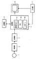
図1は、本発明による視覚化するための装置のブロック図を概略的に示す。データ取得ユニット2を使用することにより、例えば患者の脚部のようなオブジェクト1の関心領域の3D画像データが取得される。この取得した3D画像データは、例えばコンピュータのハードディスクのようなメモリ3に記憶され、適切なやり方でプログラミングされたコンピュータのCPUのような処理ユニット4により処理される。この処理ユニット4は、別々のビューを生成及び視覚化するための別々のユニットを有し、これらビューは、異なる透視図から及び/又は異なるビューモードで関心のある管状構造をユーザが見ることができるように、本発明に従ってリンク付けされている。特に、処理ユニット4は、この管状構造の象徴的な経路ビューを生成するための第1のユニット41、前記管状構造を示すCPRビューを生成及び視覚化するための第2のユニット42、及び少なくとも1つの平面ビュー、好ましくは3つの直交するビューを生成するための第3のユニット43を有する。処理中に使用される特定のデータを記憶するために、分離したメモリ5が設けられる。前記別々のビューはディスプレイスクリーン6に表示されることができ、このスクリーンは前記別々のビューを同時に示すための別個のウィンドウを好ましくは持っている。最後に、ユーザ入力及び透視図又はその種類の他のパラメタの選択のための入力ユニット7が設けられている。
FIG. 1 schematically shows a block diagram of an apparatus for visualization according to the invention. By using the data acquisition unit 2, 3D image data of a region of interest of the
以下において、1つの可能な操作方法が実施例として説明されるものである。この実施例において、患者の脚部の医療用3D画像データセットが取得され、1つの脚部内にある血管の経路が検査されると仮定される。これにより、第1のステップにおいて及び第1の処理ユニット41を使用することにより、この脚部における血管の経路の象徴的な経路ビューが生成される。この血管の経路を抽出する別の方法も知られ、自動抽出方法は国際特許公開番号WO03/021532 A2に記載され、これと共に参照を行う。結果として、図2に示されるような象徴的な経路ビューBが得られ、このビューにおいて、これに対する3D画像データセットが得られた脚部の一部における血管の経路の異なる分岐B1、B2、B3が図示されている。この象徴的な経路ビューBは、次いで、ディスプレイ6上に例えば別個のウィンドウで表示されることができる。
In the following, one possible operating method is described as an example. In this example, it is assumed that a medical 3D image data set of a patient's leg is acquired and the path of a blood vessel in one leg is examined. Thereby, in the first step and by using the
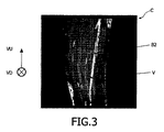
次のステップとして、第2の処理ユニット42を使用することにより、CPRビューは、選択した血管の分岐に対する湾曲した平面の長軸方向の断面図を生成することにより、すなわち象徴的な経路ビューBに示される分岐B1、B2、B3のうち1つをユーザが選択することができる入力ユニット7を使用することにより、特に生成される。これに対してCPRビューが生成及び視覚化される。図2に示される実施例において、ユーザが血管の分岐B2を選択し、それに対し図3に示されるようなCPRビューCが生成される。それに見られるように、この血管の分岐B2の全長は、この血管がある単一平面に完全に置かれなくてもCPRビューに示される、すなわちCPRビューCは通常、関心のあるオブジェクトを通る、湾曲した平面に沿った画像データを示している歪んだビューである。CPRビューを生成する別の方法は既知であり、ここでさらに論じることはしない。特に上述した論文Armin Kanitsar他著、“CPR-Curved Planar Reformation”を参照する。本発明に従い使用するために、CPRビューを生成するどの特定の方法が利用されるかは関係ない。
As a next step, by using the
述べたように、一般的にCPRビューにおいて、このCPRビューCの視野方向VD及びビューアップ方向VUは、ユーザにより事前に設定されることも可能であり、又はデフォルトのパラメタとして与えられる。 As described above, in general, in the CPR view, the field-of-view direction VD and the view-up direction VU of the CPR view C can be set in advance by the user or are given as default parameters.
このCPRビューC及び/又は象徴的な経路ビューBを使用することにより、ユーザは、血管の経路の選択した分岐B2に沿って経路ポイントを選択することができ、そのために少なくとも1つの平面ビューが生成されると共に表示される。この選択した経路ポイントは、示される実施例においてCPRビューCにおいて選択されたビューイングポイントVと呼ばれる。選択したビューイングポイントVの3D空間位置データは、この3D位置データが全ての経路ポイントに対し利用可能であるので、簡単に得ることができ、CPRポイントは、この経路の長さにポイントを直接マッピングする。好ましくは、象徴的な経路ビューBにおける血管の経路の各経路ポイントに対し、前記3D空間位置データは既知であり、記憶装置5に記憶されているので、CPRビューCにおいてビューイングポイントVを選択した後、前記象徴的な経路ビューBにおける対応する経路ポイントV’にリンク付けされ、そこから割り当てられた3D空間位置データが記憶媒体5から取り出されることができる。 By using this CPR view C and / or the symbolic route view B, the user can select a route point along the selected branch B2 of the vessel route so that at least one planar view is present. Generated and displayed. This selected path point is referred to as the viewing point V selected in CPR view C in the illustrated embodiment. The 3D spatial position data of the selected viewing point V can be easily obtained because this 3D position data is available for all path points, and the CPR point can be obtained directly from the length of this path. Map. Preferably, for each path point of the vascular path in the symbolic path view B, the 3D spatial position data is known and stored in the storage device 5, so that the viewing point V is selected in the CPR view C After that, the 3D spatial position data linked to and assigned from the corresponding route point V ′ in the symbolic route view B can be retrieved from the storage medium 5.
第3のステップにおいて、第3の処理ユニット43を用いることにより、前記ビューイングポイントVを通る少なくとも1つの平面ビューが次いで、メモリ3に記憶されている本来の3D画像データから生成される。好ましくは、3つの直交するビューO1、O2、O3が既知のオルトビューアにより生成され、ここで前記ビューイングポイントVはこれら3つの直交する平面が交差するポイントを決める。CPRビューC及び1つ以上の平面ビューO1、O2、O3は、次いでディスプレイ6上の別個のウィンドウにおいて象徴的な経路ビューBと同時に表示される。前記ビューイングポイントVにおいて交差する3つの直交するビューO1、O2、O3が図4に示されている。
In a third step, by using a
入力ユニット7を使用することにより、ユーザは、例えば図3に示されるCPRビューCにおいてポインタを上方及び下方に動かすことにより、ビューイングポイントVの位置をインタラクティブに変化させる可能性を持つ。前記ビューイングポイントVの各変化の際に、少なくとも1つの平面ビューは、象徴的な経路ビュー、CPRビュー及び少なくとも1つの平面ビューからの情報を同時に用いて、ユーザが前記経路及び前記管状構造の周囲組織の完全な概要を得ることができるように、自動的且つ略リアルタイムで更新される。本発明は、幾つかの場合において、(例えばbalanced-FFE法のような新規磁気共鳴アンギオグラフィ手法において)最大値投影(MIP)ビューが妥協される場合、如何なる種類の3D画像データにも対する、素早い管状構造を目的とするビューイングを可能にし、スライスの様式で経路を追従(トラッキング)するのに必要な退屈な対話の程度を減少させる。管状構造に対する画像データは、前記CPRビューアにリンク付けされた3Dの象徴的な経路ビューアを介して焦点が合わされることができ、この経路上にある生データはCPRオルトビューアリンクを用いてレビューされることができる。特に血管のナビゲーションのような、効果的なナビゲーション方法の重要性は、例えばbalanced FFE/TFE技法及びブラッドプール造影剤(bloodpool contrast agent)のような新しいMRアンギオグラフィ手法の出現と共に高くなってきている。これにより、本発明は例えばCTアンギオグラフィデータ、3D回転アンギオグラフィデータ又はMRデータを使用する医療撮像に好ましくは用いられる。しかしながら、本発明は固体要素における毛細管のようなクラックを検出するための材料検査のような他の技術分野にも応用されてもよい。 By using the input unit 7, the user has the possibility to interactively change the position of the viewing point V, for example, by moving the pointer up and down in the CPR view C shown in FIG. At each change of the viewing point V, at least one planar view simultaneously uses information from the symbolic path view, the CPR view and the at least one plane view so that the user can identify the path and the tubular structure. It is updated automatically and in near real time so that a complete overview of the surrounding tissue can be obtained. The present invention, in some cases (for example in new magnetic resonance angiography techniques such as the balanced-FFE method), for any kind of 3D image data when the maximum projection (MIP) view is compromised. Allows viewing aimed at a quick tubular structure and reduces the amount of tedious interaction required to follow the path in a sliced manner. Image data for the tubular structure can be focused through a 3D symbolic path viewer linked to the CPR viewer, and the raw data on this path is reviewed using the CPR ortho viewer link. Can. The importance of effective navigation methods, especially vascular navigation, is increasing with the advent of new MR angiography techniques such as balanced FFE / TFE techniques and bloodpool contrast agents. . Thereby, the present invention is preferably used for medical imaging using, for example, CT angiography data, 3D rotation angiography data, or MR data. However, the present invention may also be applied to other technical fields such as material inspection to detect capillary-like cracks in solid elements.
本発明は、より効果的な視覚化を提供することにより、3Dデータにおける複雑な経路の良好な概要をユーザが得ることを可能にする方法を提供する。本発明は、象徴的なビューと、存在する3D画像データとの密な統合を提供する。局部的な経路の実際のビューよりも、目標とする経路の概要(CPR)が前記データへのリンクに用いられ、好ましくは使用される3Dの象徴的なビューアは、ツリー構造からなるより直観的なナビゲーションを可能にする。 The present invention provides a method that allows a user to get a good overview of complex paths in 3D data by providing more effective visualization. The present invention provides a tight integration between the symbolic view and the existing 3D image data. Rather than the actual view of the local path, the target path summary (CPR) is used to link to the data, preferably the 3D symbolic viewer used is more intuitive with a tree structure. Navigation is possible.
Claims (10)
−前記管状構造の象徴的な経路ビューからCPRビューを生成及び視覚化するステップであり、前記象徴的な経路ビューは前記管状構造を示し、前記象徴的な経路の経路ポイントは3D空間位置データを割り当てられるステップ、及び
−前記CPRビュー又は前記象徴的な経路ビューにおいて選択された前記管状構造のビューイングポイントを介して、前記オブジェクトの少なくとも1つの平面ビューを生成及び視覚化するステップ
を有する方法。 In a method of visualizing a tubular structure of an object by using a 3D image data set of the object,
Generating and visualizing a CPR view from the symbolic path view of the tubular structure, wherein the symbolic path view indicates the tubular structure, and the path point of the symbolic path represents 3D spatial position data; Assigning and generating and visualizing at least one planar view of the object via the viewing point of the tubular structure selected in the CPR view or the symbolic path view.
−前記3D画像データを記憶する手段、
−前記管状構造の象徴的な経路ビューからCPRビューを生成する手段であり、前記象徴的な経路ビューは前記管状構造を示し、前記象徴的な経路の経路ポイントは3D空間位置データを割り当てられる手段、
−前記象徴的な経路の前記3D空間位置データを記憶する手段、
−前記CPRビュー又は前記象徴的な経路ビューにおいて選択された前記管状構造のビューイングポイントを介して、前記オブジェクトの少なくとも1つの平面ビューを生成する手段、
−前記象徴的な経路ビュー、前記CPRビュー及び前記少なくとも1つの平面ビューを視覚化する手段、及び
−前記CPRビュー又は前記象徴的な経路ビューにおいてビューイングポイントを選択する手段
を有する装置。 In an apparatus for visualizing a tubular structure of an object by using a 3D image data set of said object,
-Means for storing said 3D image data;
Means for generating a CPR view from the symbolic path view of the tubular structure, wherein the symbolic path view indicates the tubular structure and the path points of the symbolic path are assigned 3D spatial position data; ,
Means for storing the 3D spatial position data of the symbolic path;
Means for generating at least one planar view of the object via a viewing point of the tubular structure selected in the CPR view or the symbolic path view;
An apparatus comprising: means for visualizing the symbolic path view, the CPR view and the at least one planar view; and means for selecting a viewing point in the CPR view or the symbolic path view.
Applications Claiming Priority (2)
| Application Number | Priority Date | Filing Date | Title |
|---|---|---|---|
| EP03104211 | 2003-11-14 | ||
| PCT/IB2004/052266 WO2005048198A1 (en) | 2003-11-14 | 2004-11-02 | Method and apparatus for visualisation of a tubular structure |
Publications (2)
| Publication Number | Publication Date |
|---|---|
| JP2007511268A true JP2007511268A (en) | 2007-05-10 |
| JP2007511268A5 JP2007511268A5 (en) | 2007-12-20 |
Family
ID=34585904
Family Applications (1)
| Application Number | Title | Priority Date | Filing Date |
|---|---|---|---|
| JP2006539012A Pending JP2007511268A (en) | 2003-11-14 | 2004-11-02 | Method and apparatus for visualizing tubular structures |
Country Status (4)
| Country | Link |
|---|---|
| US (1) | US20070133849A1 (en) |
| EP (1) | EP1687778A1 (en) |
| JP (1) | JP2007511268A (en) |
| WO (1) | WO2005048198A1 (en) |
Cited By (5)
| Publication number | Priority date | Publication date | Assignee | Title |
|---|---|---|---|---|
| JP2009207890A (en) * | 2008-02-28 | 2009-09-17 | Ethicon Endo Surgery Inc | Gui for implantable restriction device and data logger |
| JP2010509971A (en) * | 2006-11-20 | 2010-04-02 | コーニンクレッカ フィリップス エレクトロニクス エヌ ヴィ | Display of anatomical tree structure |
| US8730234B2 (en) | 2010-08-31 | 2014-05-20 | Canon Kabushiki Kaisha | Image display apparatus and image display method |
| US10204409B2 (en) | 2015-06-04 | 2019-02-12 | Samsung Electronics Co., Ltd. | Apparatus and method of processing medical image |
| JP2020501659A (en) * | 2016-12-08 | 2020-01-23 | コーニンクレッカ フィリップス エヌ ヴェKoninklijke Philips N.V. | Simplified navigation of spinal medical imaging data |
Families Citing this family (13)
| Publication number | Priority date | Publication date | Assignee | Title |
|---|---|---|---|---|
| US8744146B2 (en) * | 2004-12-06 | 2014-06-03 | Siemens Aktiengellschaft | Vascular reformatting using curved planar reformation |
| JP2009544394A (en) * | 2006-07-25 | 2009-12-17 | コーニンクレッカ フィリップス エレクトロニクス エヌ ヴィ | Curved multi-slice display method and apparatus |
| EP2156407A1 (en) | 2007-06-07 | 2010-02-24 | Koninklijke Philips Electronics N.V. | Inspection of tubular-shaped structures |
| US8730237B2 (en) | 2007-08-03 | 2014-05-20 | Koninklijke Philips N.V. | Coupling the viewing direction of a blood vessel's CPR view with the viewing angle on the 3D tubular structure's rendered voxel volume and/or with the C-arm geometry of a 3D rotational angiography device's C-arm system |
| US8854355B2 (en) * | 2009-12-11 | 2014-10-07 | General Electric Company | System and method of visualizing features in an image |
| US10004557B2 (en) | 2012-11-05 | 2018-06-26 | Pythagoras Medical Ltd. | Controlled tissue ablation |
| EP3139853B1 (en) | 2014-05-07 | 2018-12-19 | Pythagoras Medical Ltd. | Controlled tissue ablation apparatus |
| US10383685B2 (en) | 2015-05-07 | 2019-08-20 | Pythagoras Medical Ltd. | Techniques for use with nerve tissue |
| US20170202614A1 (en) * | 2016-01-20 | 2017-07-20 | Rainbow Medical Ltd. | Catheter guidance and procedure planning |
| CN114376588A (en) * | 2016-03-13 | 2022-04-22 | 乌泽医疗有限公司 | Apparatus and method for use with bone surgery |
| US11678932B2 (en) | 2016-05-18 | 2023-06-20 | Symap Medical (Suzhou) Limited | Electrode catheter with incremental advancement |
| WO2019044611A1 (en) * | 2017-08-28 | 2019-03-07 | キヤノン株式会社 | Information processing device, information processing method, and program |
| EP4125610B1 (en) | 2020-04-03 | 2023-08-02 | Koninklijke Philips N.V. | Computer-implemented method for visualization of an elongated anatomical structure |
Citations (3)
| Publication number | Priority date | Publication date | Assignee | Title |
|---|---|---|---|---|
| JPH087080A (en) * | 1994-06-22 | 1996-01-12 | Hitachi Medical Corp | Image diagnostic device |
| JP2002092590A (en) * | 2000-09-14 | 2002-03-29 | Hitachi Medical Corp | Image display device |
| JP2002330959A (en) * | 2001-05-08 | 2002-11-19 | Hitachi Medical Corp | Three-dimensional image display device |
Family Cites Families (6)
| Publication number | Priority date | Publication date | Assignee | Title |
|---|---|---|---|---|
| US6034695A (en) * | 1996-08-02 | 2000-03-07 | Autodesk, Inc. | Three dimensional modeling and animation system |
| US6331116B1 (en) * | 1996-09-16 | 2001-12-18 | The Research Foundation Of State University Of New York | System and method for performing a three-dimensional virtual segmentation and examination |
| US6718193B2 (en) * | 2000-11-28 | 2004-04-06 | Ge Medical Systems Global Technology Company, Llc | Method and apparatus for analyzing vessels displayed as unfolded structures |
| JP4319031B2 (en) * | 2001-09-06 | 2009-08-26 | コーニンクレッカ フィリップス エレクトロニクス エヌ ヴィ | Object segmentation method and apparatus |
| US7570802B2 (en) * | 2001-12-27 | 2009-08-04 | The United States Of America As Represented By The Secretary Of The Department Of Health And Human Services | Automated centerline detection algorithm for colon-like 3D surfaces |
| GB2395880B (en) * | 2002-11-27 | 2005-02-02 | Voxar Ltd | Curved multi-planar reformatting of three-dimensional volume data sets |
-
2004
- 2004-11-02 WO PCT/IB2004/052266 patent/WO2005048198A1/en active Application Filing
- 2004-11-02 EP EP04770356A patent/EP1687778A1/en not_active Withdrawn
- 2004-11-02 JP JP2006539012A patent/JP2007511268A/en active Pending
- 2004-11-02 US US10/595,694 patent/US20070133849A1/en not_active Abandoned
Patent Citations (3)
| Publication number | Priority date | Publication date | Assignee | Title |
|---|---|---|---|---|
| JPH087080A (en) * | 1994-06-22 | 1996-01-12 | Hitachi Medical Corp | Image diagnostic device |
| JP2002092590A (en) * | 2000-09-14 | 2002-03-29 | Hitachi Medical Corp | Image display device |
| JP2002330959A (en) * | 2001-05-08 | 2002-11-19 | Hitachi Medical Corp | Three-dimensional image display device |
Cited By (6)
| Publication number | Priority date | Publication date | Assignee | Title |
|---|---|---|---|---|
| JP2010509971A (en) * | 2006-11-20 | 2010-04-02 | コーニンクレッカ フィリップス エレクトロニクス エヌ ヴィ | Display of anatomical tree structure |
| JP2009207890A (en) * | 2008-02-28 | 2009-09-17 | Ethicon Endo Surgery Inc | Gui for implantable restriction device and data logger |
| US8730234B2 (en) | 2010-08-31 | 2014-05-20 | Canon Kabushiki Kaisha | Image display apparatus and image display method |
| US10204409B2 (en) | 2015-06-04 | 2019-02-12 | Samsung Electronics Co., Ltd. | Apparatus and method of processing medical image |
| JP2020501659A (en) * | 2016-12-08 | 2020-01-23 | コーニンクレッカ フィリップス エヌ ヴェKoninklijke Philips N.V. | Simplified navigation of spinal medical imaging data |
| JP7191020B2 (en) | 2016-12-08 | 2022-12-16 | コーニンクレッカ フィリップス エヌ ヴェ | Simplified Navigation of Spine Medical Imaging Data |
Also Published As
| Publication number | Publication date |
|---|---|
| US20070133849A1 (en) | 2007-06-14 |
| WO2005048198A1 (en) | 2005-05-26 |
| EP1687778A1 (en) | 2006-08-09 |
Similar Documents
| Publication | Publication Date | Title |
|---|---|---|
| JP2007511268A (en) | Method and apparatus for visualizing tubular structures | |
| US7546154B2 (en) | Method and apparatus for automatic detection of anomalies in vessel structures | |
| JP6039903B2 (en) | Image processing apparatus and operation method thereof | |
| JP5417609B2 (en) | Medical diagnostic imaging equipment | |
| JP5661283B2 (en) | System, operating method and computer-readable storage medium for displaying anatomical tree structure | |
| US20060104545A1 (en) | Computer readable medium for image processing and image processing method | |
| US8050475B2 (en) | Detection and localization of vascular occlusion from angiography data | |
| US10052032B2 (en) | Stenosis therapy planning | |
| JP2010528750A (en) | Inspection of tubular structures | |
| JP5785120B2 (en) | Medical image diagnosis support apparatus and method, and program | |
| JP2006246941A (en) | Image processing apparatus and vessel tracking method | |
| JP6214646B2 (en) | Temporal anatomical target tagging in angiograms | |
| JP2010264232A (en) | Apparatus, program and method for supporting diagnosis | |
| RU2419882C2 (en) | Method of visualising sectional planes for arched oblong structures | |
| JP2011125570A (en) | Image processor, image processing method and program | |
| EP2116974A1 (en) | Statistics collection for lesion segmentation | |
| US7860282B2 (en) | Method for supporting an interventional medical operation | |
| JP2015515296A (en) | Providing image information of objects | |
| JPWO2010055817A1 (en) | Image processing apparatus and image processing method | |
| JP3927488B2 (en) | Image processing method, image processing apparatus, and program | |
| JP2010042065A (en) | Medical image processor, processing method | |
| JP2010284405A (en) | Medical image processor, medical image diagnostic device and medical image processing program | |
| JP2014144156A (en) | Medical image display control device and method, and program | |
| JP6487999B2 (en) | Information processing apparatus, information processing method, and program | |
| JP5414249B2 (en) | Image display device |
Legal Events
| Date | Code | Title | Description |
|---|---|---|---|
| A521 | Written amendment |
Free format text: JAPANESE INTERMEDIATE CODE: A523 Effective date: 20071101 |
|
| A621 | Written request for application examination |
Free format text: JAPANESE INTERMEDIATE CODE: A621 Effective date: 20071101 |
|
| A131 | Notification of reasons for refusal |
Free format text: JAPANESE INTERMEDIATE CODE: A131 Effective date: 20091027 |
|
| A02 | Decision of refusal |
Free format text: JAPANESE INTERMEDIATE CODE: A02 Effective date: 20100323 |