JP2007508619A - Wake-on-touch for vibration-sensitive touch input devices - Google Patents
Wake-on-touch for vibration-sensitive touch input devices Download PDFInfo
- Publication number
- JP2007508619A JP2007508619A JP2006533930A JP2006533930A JP2007508619A JP 2007508619 A JP2007508619 A JP 2007508619A JP 2006533930 A JP2006533930 A JP 2006533930A JP 2006533930 A JP2006533930 A JP 2006533930A JP 2007508619 A JP2007508619 A JP 2007508619A
- Authority
- JP
- Japan
- Prior art keywords
- touch
- vibration
- wake
- substrate
- intentional
- Prior art date
- Legal status (The legal status is an assumption and is not a legal conclusion. Google has not performed a legal analysis and makes no representation as to the accuracy of the status listed.)
- Withdrawn
Links
Images


Classifications
-
- G—PHYSICS
- G06—COMPUTING; CALCULATING OR COUNTING
- G06F—ELECTRIC DIGITAL DATA PROCESSING
- G06F3/00—Input arrangements for transferring data to be processed into a form capable of being handled by the computer; Output arrangements for transferring data from processing unit to output unit, e.g. interface arrangements
- G06F3/01—Input arrangements or combined input and output arrangements for interaction between user and computer
- G06F3/03—Arrangements for converting the position or the displacement of a member into a coded form
- G06F3/041—Digitisers, e.g. for touch screens or touch pads, characterised by the transducing means
- G06F3/043—Digitisers, e.g. for touch screens or touch pads, characterised by the transducing means using propagating acoustic waves
-
- G—PHYSICS
- G06—COMPUTING; CALCULATING OR COUNTING
- G06F—ELECTRIC DIGITAL DATA PROCESSING
- G06F1/00—Details not covered by groups G06F3/00 - G06F13/00 and G06F21/00
- G06F1/26—Power supply means, e.g. regulation thereof
- G06F1/32—Means for saving power
- G06F1/3203—Power management, i.e. event-based initiation of a power-saving mode
-
- G—PHYSICS
- G06—COMPUTING; CALCULATING OR COUNTING
- G06F—ELECTRIC DIGITAL DATA PROCESSING
- G06F3/00—Input arrangements for transferring data to be processed into a form capable of being handled by the computer; Output arrangements for transferring data from processing unit to output unit, e.g. interface arrangements
- G06F3/01—Input arrangements or combined input and output arrangements for interaction between user and computer
- G06F3/03—Arrangements for converting the position or the displacement of a member into a coded form
- G06F3/033—Pointing devices displaced or positioned by the user, e.g. mice, trackballs, pens or joysticks; Accessories therefor
- G06F3/0354—Pointing devices displaced or positioned by the user, e.g. mice, trackballs, pens or joysticks; Accessories therefor with detection of 2D relative movements between the device, or an operating part thereof, and a plane or surface, e.g. 2D mice, trackballs, pens or pucks
- G06F3/03547—Touch pads, in which fingers can move on a surface
-
- G—PHYSICS
- G06—COMPUTING; CALCULATING OR COUNTING
- G06F—ELECTRIC DIGITAL DATA PROCESSING
- G06F3/00—Input arrangements for transferring data to be processed into a form capable of being handled by the computer; Output arrangements for transferring data from processing unit to output unit, e.g. interface arrangements
- G06F3/01—Input arrangements or combined input and output arrangements for interaction between user and computer
- G06F3/03—Arrangements for converting the position or the displacement of a member into a coded form
- G06F3/041—Digitisers, e.g. for touch screens or touch pads, characterised by the transducing means
- G06F3/0416—Control or interface arrangements specially adapted for digitisers
- G06F3/04162—Control or interface arrangements specially adapted for digitisers for exchanging data with external devices, e.g. smart pens, via the digitiser sensing hardware
Abstract
タッチ入力装置の基板内を伝播する屈曲波振動が感知される。意図的タッチを示す基板内を伝播する感知振動と非意図的タッチを示す基板内を伝播する感知振動との識別に対応する。意図的タッチを示す基板内を伝播する感知振動に応答して、ウェイクアップ信号が生成される。ウェイクアップ信号はタッチ入力装置の制御システムに通信されて、制御システムを休眠状態から動作状態に移行する。 Bending wave vibration propagating in the substrate of the touch input device is detected. This corresponds to the discrimination between the sensed vibration propagating in the substrate showing the intentional touch and the sensed vibration propagating in the substrate showing the unintentional touch. A wake-up signal is generated in response to a sensed vibration propagating through the substrate that indicates an intentional touch. The wake-up signal is communicated to the control system of the touch input device to shift the control system from the sleep state to the operating state.
Description
本発明はタッチ入力装置に関し、特にウェイクオンタッチ感知技術(wake-on-touch sensing technique)を用いた振動感知タッチ入力装置に関する。 The present invention relates to a touch input device, and more particularly, to a vibration sensing touch input device using a wake-on-touch sensing technique.
タッチ入力機能を用いた電子ディスプレイが携帯またはハンドヘルド装置を始めとする多様な装置内で用いられている。典型的なタッチスクリーンが電子ディスプレイのオーバーレイ(上張り)として構成されている。このタッチスクリーンをタッチセンサとしての透明導電層と外周の周囲に配置された導電性材料で形成された電極のパターンとを有する容量式または抵抗式タッチスクリーンとして構成し得る。代替的にタッチスクリーンはタッチを感知する振動センサを用い得る。タッチ場所はタッチセンサにより生成されたタッチ信号を用いた多様な方法で判定することができる。 Electronic displays using a touch input function are used in various devices such as portable or handheld devices. A typical touch screen is configured as an electronic display overlay. This touch screen can be configured as a capacitive or resistive touch screen having a transparent conductive layer as a touch sensor and a pattern of electrodes formed of a conductive material arranged around the outer periphery. Alternatively, the touch screen may use a vibration sensor that senses the touch. The touch location can be determined by various methods using the touch signal generated by the touch sensor.
携帯及びハンドヘルド電子装置への関心の高まりの結果このような装置が増加してきた。この関心はこれに付随して特に所要電力の点で携帯/ハンドヘルド装置の寿命の延長への関心を高めた。タッチ入力装置における電力消費を削減する技術の実施はタッチ入力機能を組み込んだ携帯電子装置の充電または電池交換イベント間の耐用年数を延ばすことができて有利である。 Increasing interest in portable and handheld electronic devices has resulted in an increase in such devices. This interest has been accompanied by an increased interest in extending the lifetime of portable / handheld devices, particularly in terms of power requirements. Implementation of techniques to reduce power consumption in touch input devices is advantageous because it can extend the useful life between charging or battery replacement events for portable electronic devices that incorporate touch input functionality.
本発明はタッチ入力装置においてウェイクオンタッチ感知を行う方法およびシステムを対象とする。また本発明は振動感知タッチ入力装置などのタッチ入力装置への意図的タッチ(intended touch)と非意図的タッチ(unintended touch)とを識別する方法およびシステムを対象とする。 The present invention is directed to a method and system for performing wake-on-touch sensing in a touch input device. The present invention is also directed to a method and system for distinguishing between an intentional touch and an unintended touch on a touch input device such as a vibration sensitive touch input device.
本発明の様々な実施形態の状況において、用語「意図的タッチ」とはタッチ入力として解釈されることを意図した検出可能な振動、このような振動を生じるイベント、およびセンサがこのような振動を受けることにより生成される信号を指す。用語「非意図的タッチ」とはタッチ入力として解釈されることを意図しない検出可能な振動、このような振動を生じるイベント、およびセンサがこのような振動を受けることにより生成される信号を指す。非意図的タッチの例には外部ノイズおよび検出された信号内に不可欠なシグネチャ(signature)を生成しないタッチ入力装置に対する振動発生衝撃がある。 In the context of various embodiments of the present invention, the term “intentional touch” refers to detectable vibrations intended to be interpreted as touch input, events that cause such vibrations, and sensors that cause such vibrations. Refers to the signal generated by receiving. The term “unintentional touch” refers to detectable vibrations that are not intended to be interpreted as touch input, events that cause such vibrations, and signals that are generated by the sensor experiencing such vibrations. An example of an unintentional touch is external noise and vibration generating shocks on a touch input device that does not generate an essential signature in the detected signal.
本発明のウェイクオンタッチ方法の一実施形態によれば、タッチ入力装置の基板内を伝播する屈曲波振動(bending wave vibration)が感知される。この方法は意図的タッチを示す基板内を伝播する感知振動と非意図的タッチを示す基板内を伝播する感知振動とを識別するステップをさらに含む。意図的タッチを示す基板内を伝播する感知振動に応答して、ウェイクアップ信号が生成される。ウェイクアップ信号はタッチ入力装置の制御システムに通信されて制御システムを休眠状態から動作状態に移行する。 According to one embodiment of the wake-on-touch method of the present invention, bending wave vibration propagating in the substrate of the touch input device is sensed. The method further includes identifying a sensed vibration that propagates in the substrate that exhibits an intentional touch and a sensed vibration that propagates in the substrate that exhibits an unintentional touch. A wake-up signal is generated in response to a sensed vibration propagating through the substrate that indicates an intentional touch. The wake-up signal is communicated to the touch input device control system to shift the control system from the sleep state to the operating state.
他の実施形態によれば、タッチ入力装置は、屈曲波振動を支持するように構成された基板と、基板に結合されるとともに、基板内を伝播する振動を感知するように構成された複数のセンサと、を含む。コントローラ電子機器がセンサに結合されるとともに、基板へ通信されたタッチを示す感知振動からの情報を用いてタッチ場所を算出するように構成されている。ウェイクアップ回路がセンサとコントローラ電子機器とに結合されている。ウェイクアップ回路は意図的タッチを示す基板内を伝播する感知振動と非意図的タッチを示す基板内を伝播する感知振動とを識別するように構成されている。ウェイクアップ回路は意図的タッチを示す基板内を伝播する感知振動に応答して、ウェイクアップ信号を生成してウェイクアップ信号をコントローラ電子機器に通信するように構成されている。 According to another embodiment, a touch input device includes a substrate configured to support bending wave vibrations and a plurality of coupled to the substrate and configured to sense vibrations propagating through the substrate. And a sensor. A controller electronics is coupled to the sensor and is configured to calculate a touch location using information from sensed vibrations indicative of a touch communicated to the substrate. A wake-up circuit is coupled to the sensor and controller electronics. The wake-up circuit is configured to distinguish between a sensed vibration that propagates in a substrate that exhibits an intentional touch and a sensed vibration that propagates in a substrate that exhibits an unintentional touch. The wake-up circuit is configured to generate a wake-up signal and communicate the wake-up signal to the controller electronics in response to a sensed vibration propagating through the substrate indicating an intentional touch.
他の実施形態によれば、タッチ入力装置は、屈曲波振動を支持するように構成された基板と、基板に結合されるとともに、基板内を伝播する振動を感知するように構成された複数のセンサと、を含む。少なくとも1つの励起変換器が基板に結合されている。励起変換器は基板に励起振動を付与する。コントローラ電子機器がセンサに結合されるとともに、基板へ通信されたタッチを示す感知振動からの情報を用いてタッチ場所を算出するように構成されている。ウェイクアップ回路がセンサと、コントローラと、励起変換器とに結合されている。ウェイクアップ回路は基板に付与されたタッチ振動に対する励起振動の応答を検出するとともに、意図的タッチを示す基板内を伝播する感知振動と非意図的タッチを示す基板内を伝播する感知振動とを識別するように構成されている。ウェイクアップ回路は意図的タッチを示す基板内を伝播する感知振動に応答して、ウェイクアップ信号を生成してウェイクアップ信号をコントローラ電子機器に通信するように構成されている。 According to another embodiment, a touch input device includes a substrate configured to support bending wave vibrations and a plurality of coupled to the substrate and configured to sense vibrations propagating through the substrate. And a sensor. At least one excitation transducer is coupled to the substrate. The excitation transducer imparts excitation vibration to the substrate. A controller electronics is coupled to the sensor and is configured to calculate a touch location using information from sensed vibrations indicative of a touch communicated to the substrate. A wake-up circuit is coupled to the sensor, the controller, and the excitation transducer. The wake-up circuit detects the response of the excitation vibration to the touch vibration applied to the substrate, and distinguishes between the sense vibration that propagates in the substrate that shows an intentional touch and the sense vibration that propagates in the substrate that shows an unintentional touch Is configured to do. The wake-up circuit is configured to generate a wake-up signal and communicate the wake-up signal to the controller electronics in response to a sensed vibration propagating through the substrate indicating an intentional touch.
上記の本発明の概要は本発明の各実施形態または各実施を説明しようとするものではない。本発明のより十分な理解に加えて利点と成果とは、添付の図面と併せて以下の詳細な説明と特許請求の範囲とを参照することにより明らかになるとともに理解できよう。 The above summary of the present invention is not intended to describe each embodiment or every implementation of the present invention. Advantages and results, as well as a more complete understanding of the present invention, will become apparent and understood by referring to the following detailed description and claims in conjunction with the accompanying drawings.
本発明は様々な変更例および代替形状に適用可能であるが、その詳細は一例として図面に示したものでありさらに詳細に説明する。しかし本発明を記載の特定の実施形態に限定しようとするものではないことは理解できよう。逆に添付の特許請求の範囲により規定されるように本発明の要旨および範囲内にある変更例、同等物および代替物をすべて網羅しようとするものである。 While the invention is applicable to various modifications and alternative forms, details thereof are shown by way of example in the drawings and will be described in further detail. However, it will be understood that the invention is not intended to be limited to the specific embodiments described. On the contrary, the intention is to cover all modifications, equivalents, and alternatives falling within the spirit and scope of the invention as defined by the appended claims.
以下の図示の実施形態の説明において、その一部分をなすとともに本発明を実行する様々な実施形態を図示を目的として示す添付の図面を参照する。これらの実施形態を用い得るとともに本発明の範囲から逸脱することなく構造的変形をなし得ることは理解できよう。 In the following description of the illustrated embodiments, reference is made to the accompanying drawings that form a part hereof, and in which are shown by way of illustration various embodiments that carry out the invention. It will be appreciated that these embodiments may be used and structural modifications may be made without departing from the scope of the present invention.
本発明は例えば圧電デバイスなどの多数のタッチセンサにより感知するタッチ基板を伝播する振動を感知するタッチ起動ユーザ入力装置に関する。特に本発明はタッチ基板に付与された屈曲波振動を感知することおよび、このような波振動がタッチ基板への意図的タッチによるものであるか非意図的タッチによるものであるかを判断することに関する。またタッチ基板へのいくつかのタッチを異なるタッチ器具または異なるタッチ力を用いて行われた他のタッチと区別することができるため、ある意図的タッチのみがウェイクオンタッチ信号として検出される。本発明はさらにウェイクオンタッチ回路および関連する、タッチ入力装置により感知された意図的タッチと非意図的タッチとの識別に応答して振動感知タッチ入力装置のコントローラ電子機器を休眠状態(sleep state)から動作状態(operational state)に移行させる方法に関する。 The present invention relates to a touch activated user input device that senses vibration propagating through a touch substrate that is sensed by a large number of touch sensors such as piezoelectric devices. In particular, the present invention senses bending wave vibration applied to the touch substrate and determines whether such wave vibration is due to intentional touch or unintentional touch on the touch substrate. About. Also, since some touches on the touch substrate can be distinguished from other touch devices or other touches made using different touch forces, only certain intentional touches are detected as wake-on touch signals. The present invention further provides a sleep state for the controller electronics of the vibration sensitive touch input device in response to the identification of the intended and unintentional touch sensed by the touch input device and associated wake on touch circuitry. The present invention relates to a method for shifting from an operational state to an operational state.
圧電センサを含む振動感知タッチ入力装置において、例えばタッチパネルプレートの平面内を伝播する振動は圧電センサに応力をかけ、センサの両端間に検出可能な電圧降下を生じる。受信される信号は直接タッチ入力の衝撃に直接起因する振動により、または存在する振動に影響を与えるタッチ入力により、例えば振動の減衰により生じ得る。また受信される信号はタッチ入力装置のユーザ取り扱いまたは取り扱いミスによる、あるいはタッチ入力装置の外部ではあるが感知される環境要因によるタッチ入力などの非意図的タッチ入力により生じ得る。 In a vibration sensing touch input device including a piezoelectric sensor, for example, vibration propagating in the plane of the touch panel plate applies stress to the piezoelectric sensor, causing a detectable voltage drop across the sensor. The received signal can be caused by vibrations directly due to the impact of the direct touch input, or by touch inputs that affect existing vibrations, for example by damping of the vibrations. The received signal may also be caused by unintentional touch input such as touch input due to user handling or mishandling of the touch input device, or due to environmental factors that are external to the touch input device but are sensed.
一タッチ感知手法によれば例えば直接タッチを示す信号を受け取ると、同じ信号を各センサにおいて受け取る時間差を用いてタッチ入力の場所を推定することができる。国際公開第2003−005292号パンフレットおよび同第0148684号パンフレット、ならびに代理人整理番号第58760US002号により出願された同一人所有の「振動感知タッチ入力装置(Vibration Sensing Touch Input Device)」と題された米国特許出願に開示されているように、伝播媒体(propagation medium)が分散性媒体(dispersive medium)である場合、複数の周波数で構成される振動波パケットは伝播するにつれて広がるとともに減衰するため信号の解読が困難になる。そのため受け取った信号を非分散性媒体(non-dispersive medium)内を伝播したかのように解読できるように変換することが提案されてきた。このような技術は屈曲波振動を検出するシステムに特に適している。 According to one touch sensing technique, for example, when a signal indicating a direct touch is received, the location of the touch input can be estimated using a time difference at which the same signal is received by each sensor. United States of America entitled “Vibration Sensing Touch Input Device” filed by WO 2003-005292 and US Pat. No. 0148684, and attorney docket number 58760US002. As disclosed in the patent application, when the propagation medium is a dispersive medium, the vibration wave packet composed of a plurality of frequencies spreads and attenuates as it propagates, so that the signal is decoded. Becomes difficult. Therefore, it has been proposed to convert the received signal so that it can be decoded as if it had propagated through a non-dispersive medium. Such a technique is particularly suitable for systems that detect bending wave vibrations.
屈曲波振動からタッチ位置を検出および判断するのに特に適した振動感知タッチ入力装置が上記した公開および出願に開示されておりこれらの全体を本明細書に援用する。このような屈曲波感知タッチ入力装置において、通例ユニモルフおよびバイモルフ圧電センサを始めとする圧電センサが用いられる。圧電センサは例えば良好な感度、比較的低コスト、適正な頑健性、場合によっては小さい形状因子、適正な安定性、および応答線形性を始めとする多数の有利な特徴利点を提供する。振動感知タッチ入力装置に用いることができる他のセンサには特に電気歪み方式、磁気歪み方式、圧電抵抗方式、音響方式および可動コイル装置がある。 Vibration sensing touch input devices that are particularly suitable for detecting and determining touch location from bending wave vibrations are disclosed in the above-mentioned publications and applications, and are incorporated herein in their entirety. In such bending wave sensing touch input devices, piezoelectric sensors such as unimorph and bimorph piezoelectric sensors are typically used. Piezoelectric sensors offer a number of advantageous feature advantages including, for example, good sensitivity, relatively low cost, proper robustness, and in some cases small form factor, proper stability, and response linearity. Other sensors that can be used in the vibration sensing touch input device include electrical strain, magnetostriction, piezoresistive, acoustic, and moving coil devices, among others.
またタッチ入力装置を採用した多数の用途はタッチ装置を介して情報を表示するために電子ディスプレイを用いている。ディスプレイは通例矩形であるので、矩形のタッチ装置を使用するのが通例であり便利である。このようにセンサが貼付されたタッチ基板は通例矩形形状である。本発明の一タッチ入力装置の実施形態によれば、振動センサをタッチ基板の角部付近に配置することができる。多数の用途がタッチ入力装置を介して視認されるディスプレイを必要としているため、センサをタッチ基板の縁部付近に配置して不所望に視認ディスプレイエリアに侵入しないようにすることが望ましい。センサをタッチ基板の角部に配置することでパネル縁部からの反射の影響を減少させることもできる。 Many applications that employ touch input devices also use electronic displays to display information via the touch device. Since the display is typically rectangular, it is customary and convenient to use a rectangular touch device. The touch substrate to which the sensor is attached in this manner is usually rectangular. According to the embodiment of the one touch input device of the present invention, the vibration sensor can be arranged near the corner of the touch substrate. Since many applications require a display that can be viewed through a touch input device, it is desirable to place sensors near the edge of the touch substrate to prevent undesirably entering the viewing display area. By arranging the sensor at the corner of the touch substrate, the influence of reflection from the panel edge can be reduced.
消費電力はタッチ入力装置を組み込んだ多くの装置、特に携帯またはハンドヘルド装置にとって設計および動作問題である。そのような装置において全体の消費電力を削減して電池交換または充電イベント間の装置使用期間を延長ことは一般に望ましい。タッチ入力装置を組み込んだ多くの装置はメインプロセッサを用いており、メインプロセッサは完全に機能すると大量の電力を消費する。このような装置はメインプロセッサ加えて、様々なシステムと周辺構成要素との間、例えばタッチ入力装置とタッチ入力装置が協働するディスプレイを支援する電子システム(例えばコンピュータシステム)との間、のI/O信号伝達およびデータ交換を調整する入出力(I/O)インターフェースプロセッサをさらに用いている場合がある。 Power consumption is a design and operational problem for many devices that incorporate touch input devices, particularly portable or handheld devices. It is generally desirable to reduce overall power consumption in such devices and extend device usage between battery replacement or charging events. Many devices that incorporate touch input devices use a main processor, which consumes a large amount of power when fully functional. Such devices include, in addition to the main processor, I between various systems and peripheral components, such as between a touch input device and an electronic system (eg, a computer system) that supports a display with which the touch input device cooperates. There may also be an input / output (I / O) interface processor that coordinates / O signaling and data exchange.
通常動作中メインプロセッサ動作および/またはI/O信号伝達/データ送信を支援するために必要なプロセッサおよび関連する回路により消費される電力が、全体のシステム所要電力の大部分に相当することは容易に理解されよう。また非使用または休止期間中のシステムの電力使用を削減することにより大幅な電力節約を達成可能であることも容易に理解されよう。電力節約技術が多様な電子装置で通常用いられているが、このような技術はタッチ場所を判定するための振動感知、特に屈曲波振動感知などある感知技術を用いたタッチ入力装置での使用に容易には適応しない。 It is easy for the power consumed by the processor and associated circuitry needed to support main processor operation and / or I / O signaling / data transmission during normal operation to represent a large portion of the overall system power requirements Will be understood. It will also be readily appreciated that significant power savings can be achieved by reducing the power usage of the system during periods of non-use or inactivity. Power saving technology is commonly used in a variety of electronic devices, but such technology is suitable for use in touch input devices that use some sensing technology such as vibration sensing to determine touch location, especially bending wave vibration sensing. Not easily adaptable.
さらにまた従来の電力節約手法は意図的タッチによる振動を非意図的タッチによる振動と識別可能な振動感知方法に容易には適応しない。本発明は本明細書で以下により詳細に説明するようにタッチ入力装置における電力節約、特に振動感知タッチ入力技術を用いたタッチ入力装置における電力節約に対処することを対象とする。また本発明は振動感知タッチ入力装置への意図的タッチと非意図的タッチとを識別する回路および技術を対象とする。 Furthermore, conventional power saving techniques do not readily adapt to vibration sensing methods that can distinguish vibrations caused by intentional touches from vibrations caused by unintentional touches. The present invention is directed to addressing power savings in touch input devices, particularly in touch input devices using vibration sensitive touch input technology, as described in more detail herein below. The present invention is also directed to circuits and techniques for discriminating between intentional and unintentional touches on vibration sensitive touch input devices.
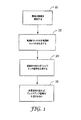
図1は本発明の実施形態による振動感知タッチ入力装置に対するウェイクオンタッチ電力節約方法に関連する様々な工程を示すフロー図である。対象のタッチ入力装置は1つまたは複数のプロセッサ(例えばメインプロセッサ、信号プロセッサ、I/Oバスプロセッサ等)と、意図的タッチの検出に応答してウェイクアップ信号を生成するウェイクオンタッチ回路と、を含むこととする。さらにウェイクアップ信号の受信に応答してプロセッサのうちの1つまたは複数が、休眠状態(例えば低減または最低消費電力モード)から動作状態(例えば完全または通常動作に関連するいくつかのまたはすべての機能を行うのに必要な休眠状態に比べて高消費電力モード)に移行することとする。 FIG. 1 is a flow diagram illustrating various steps associated with a wake-on-touch power saving method for a vibration sensitive touch input device according to an embodiment of the present invention. The target touch input device includes one or more processors (eg, a main processor, a signal processor, an I / O bus processor, etc.) and a wake-on-touch circuit that generates a wake-up signal in response to detection of an intentional touch; Is included. In addition, in response to receiving the wake-up signal, one or more of the processors may change from a sleep state (eg, reduced or lowest power consumption mode) to an operating state (eg, some or all functions associated with full or normal operation). The mode is shifted to a high power consumption mode (compared to a sleep state necessary for performing the above).
この手法によればタッチ入力装置のタッチ感知面との接触によるあるいは付加される屈曲波振動が感知される20。感知された振動は解析または評価され、その感知された振動がユーザによる意図的タッチの結果であるかまたはタッチ入力装置への非意図的タッチの結果であるかを判定する22。タッチ入力装置へのタッチが意図的だったという判定に応答してウェイクアップ信号が生成される24。一方タッチ入力装置へのタッチが非意図的だったという判定である場合には、ウェイクアップ信号は生成されない26。 According to this method, bending wave vibration caused by or added to the touch sensing surface of the touch input device is sensed 20. The sensed vibration is analyzed or evaluated to determine 22 whether the sensed vibration is the result of an intentional touch by the user or an unintentional touch to the touch input device. A wake-up signal is generated 24 in response to a determination that the touch on the touch input device was intentional. On the other hand, if it is determined that the touch on the touch input device was unintentional, no wake-up signal is generated 26.
図2は本発明の他の実施形態による振動感知タッチ入力装置のためのウェイクオンタッチ電力節約方法に関連する様々な工程を示すフロー図である。図1を参照して上記した実施形態と同様に、対象のタッチ入力装置は1つまたは複数のプロセッサと、意図的タッチの検出に応答してウェイクアップ信号を生成するウェイクオンタッチ回路を含むこととする。 FIG. 2 is a flow diagram illustrating various steps associated with a wake-on-touch power saving method for a vibration sensitive touch input device according to another embodiment of the present invention. Similar to the embodiment described above with reference to FIG. 1, the subject touch input device includes one or more processors and a wake-on-touch circuit that generates a wake-up signal in response to detection of an intentional touch. And
図2に示すようにタッチ入力装置のタッチ感知面との接触によるあるいは付加される屈曲波振動が感知される50。感知された振動は解析または評価され、その感知された振動がユーザによる意図的タッチの結果であるかまたはタッチ入力装置への非意図的タッチの結果であるかを判定する。感知された屈曲波振動は処理されて、意図的タッチと非意図的タッチとの識別を容易にするように設定された閾値またはプロファイルと比較される52。以下により詳細に説明するように意図的タッチと非意図的タッチとの間の識別は、例えば閾値とのタッチ信号振幅比較、閾値とのフィルタリングされたタッチ信号比較、時間領域評価(例えば信号特徴相関分析)、および周波数領域評価(例えば離散型フーリエ変換(DFT:Discrete Fourier Transform)解析)を始めとする多数の方法で達成することができる。 As shown in FIG. 2, bending wave vibrations due to or added to the touch sensing surface of the touch input device are sensed 50. The sensed vibration is analyzed or evaluated to determine whether the sensed vibration is the result of an intentional touch by the user or an unintentional touch to the touch input device. The sensed bending wave vibrations are processed and compared 52 with a threshold or profile set to facilitate discrimination between intentional and unintentional touches. As described in more detail below, the distinction between intentional and unintentional touches can include, for example, touch signal amplitude comparison with a threshold, filtered touch signal comparison with a threshold, time domain evaluation (eg, signal feature correlation) Analysis), and frequency domain evaluation (eg, Discrete Fourier Transform (DFT) analysis) and many other methods.
評価54が感知された振動が意図的タッチを表わしていないということを示す場合には、ウェイクアップ信号は生成されず56、1つまたは複数のプロセッサ(例えばメインプロセッサおよびI/Oバスプロセッサ)は休眠状態または他のタイプの電力節約モードのままである。評価54が感知された振動が意図的タッチを表わしているということを示す場合には、ウェイクアップ信号が生成される58。ウェイクアップ信号はタッチ入力装置の制御システムの少なくとも1つのプロセッサまたは回路あるいは電子装置に通信される60。 If rating 54 indicates that the sensed vibration does not represent an intentional touch, no wake-up signal is generated 56 and one or more processors (eg, main processor and I / O bus processor) Stay in a dormant state or other type of power saving mode. If rating 54 indicates that the sensed vibration represents an intentional touch, a wake-up signal is generated 58. The wake-up signal is communicated 60 to at least one processor or circuit or electronic device of the control system of the touch input device.
一手法ではウェイクアップ信号が1つのプロセッサに通信され、このプロセッサが1つまたは複数のウェイクアップ信号をタッチ入力装置の他のプロセッサ、構成要素または装置に通信する。他の手法では複数のウェイクアップ信号をタッチ入力装置の複数のプロセッサ、構成要素または装置に通信することができる。ウェイクアップ信号の受信に応答して受信構成要素は休眠状態から活動状態へ移行する62。 In one approach, a wake-up signal is communicated to one processor, which communicates one or more wake-up signals to other processors, components or devices of the touch input device. In other approaches, multiple wake-up signals can be communicated to multiple processors, components or devices of the touch input device. In response to receiving the wake-up signal, the receiving component transitions 62 from a sleep state to an active state.
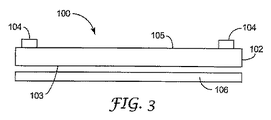
図3および4は本発明のウェイクオンタッチ方法を含むタッチ入力装置での使用に適したタッチパネル100の描写である。この実施形態によればタッチパネル100は基板102と、基板102の上面105に結合された振動センサ104と、を含む。この図示例において上面105はタッチ感知面を規定している。センサ104は上面105に結合されて示されているが、代替的にはセンサをタッチパネル100の下面103に結合することができる。他の実施形態において1つまたは複数のセンサを上面105に結合する一方で1つまたは複数の他のセンサを下面103に結合し得る。
3 and 4 are depictions of a
基板102は対象の振動、例えば屈曲波振動を支持する基板であればよい。例示的基板にはアクリルまたはポリカーボネートなどのプラスチック類、ガラス、または他の好適な材料がある。基板102は透明または不透明でもよく、場合によっては他の層を含むまたは組み込むあるいはさらなる機能性を支持することができる。例えば基板102は耐引掻性、耐汚染性、ぎらつき防止、反射防止性、方向性または守秘用光制御、フィルタリング、偏光、光学補償、摩擦構造化、着色、グラフィカルイメージ等を提供することができる。
The board |
一般にタッチパネル100は2次元のタッチ入力の位置を決定するためには少なくとも3つのセンサ104を含み、国際公開第2003−005292号パンフレットおよび同第0148684号パンフレットに説明されているように、いくつかの実施形態では4つのセンサ104が望ましい。本発明ではセンサ104は基板102へのタッチ入力を示す振動を感知することができる圧電センサである。例示的な圧電デバイスはPZT結晶を用いている。
In general, the
一実施形態においてセンサ104はすべて基板102内の振動を感知するように構成されている。他の実施形態ではセンサ104のうちの1つまたは複数をエミッタ装置として用いて信号を発してその信号を他のセンサ104によって感知して基準信号として用いることが可能であり、またはタッチ入力を受けると変化する振動を生成してその変化した振動をセンサ104によって感知してタッチの位置を判定することができる。電気的力学的変換器を好適なエミッタ装置として用い得る。さらにまたセンサ104のうちの1つまたは複数を感知および励起変換器として構成することができる。センサ104を接着剤の使用によるなど任意の適当な手段により基板102に貼付または接着することができる。
In one embodiment, all
図3に図示した実施形態では、随意のディスプレイ装置106がタッチパネル100に近接配置して示されている。ディスプレイ装置106は通例タッチパネル100を介して視認者位置に向けて情報を表示するために用いられる。ディスプレイ装置106は任意の好適な電子ディスプレイ、例えば液晶ディスプレイ、エレクトロルミネセントディスプレイ、冷陰極管ディスプレイ、プラズマディスプレイ、発光ダイオードディスプレイ等でもよい。ディスプレイ装置106は追加的にまたは代替的に永久または交換可能な静止画像を含み得る。
In the embodiment illustrated in FIG. 3, an
図5Aはタッチパネル100に通信可能に結合されたコントローラ電子機器200の実施形態を示す。コントローラ電子機器200は通例タッチパネル100も含むタッチ入力装置内に組み込まれているが、特定の設計で望ましい場合にはコントローラ電子機器200のいくつかのまたはすべての要素をタッチパネル筐体の外部に組み込み得る。インターフェース202はタッチパネル100をコントローラ電子機器200に通信可能に結合する。コントローラ電子機器200はメインプロセッサ206と、ウェイクオンタッチ回路210と、を含む。図5Aに示した構成によればウェイクオンタッチ回路210はメインプロセッサ206とインターフェース202とに結合されている。
FIG. 5A shows an embodiment of
この構成においてメインプロセッサ206はタッチ位置特定計算、較正、および他の関連機能の実行を担当する。またメインプロセッサ206はインターフェース202を介するタッチパネル100とコントローラ電子機器200との間、およびバス209を介するコントローラ電子機器200と外部システムまたは周辺機器との間の信号送信も管理する。メインプロセッサ206はデジタル信号プロセッサ(DSP:Digital Signal Processor)を組み込んでおり好適である。バス209はメインプロセッサ206を、図5Aのタッチ入力装置と協働するコンピュータまたはディスプレイシステムなどの他のシステムまたは装置と通信可能に結合する。
In this configuration,
タッチパネル100からコントローラ電子機器200に通信された信号は通例、タッチセンサ104により生成されたアナログ電流信号であり、アナログ電流信号をタッチパネル100とコントローラ電子機器200との間に設けられた回路によって、またはメインプロセッサ206の回路によってアナログまたはデジタル電圧信号に変換できることは理解されよう。また1つまたは複数のエミッタまたはエミッタ/センサがタッチパネル100の基板102上に設けられている場合、励起信号をコントローラ電子機器200からタッチパネル100に通信することができる。
The signal communicated from the
ウェイクオンタッチ回路210がセンサ104により生成されたタッチ(意図的または非意図的)入力信号を感知する目的でインターフェース202に結合して示されている。ウェイクオンタッチ回路210は通例、インターフェース202を介するタッチパネル100とコントローラ電子機器200との間の感知信号の送信に悪影響を与えないように高入力インピーダンスを有するように構成されている。
A wake on
他の構成ではウェイクオンタッチ回路210をインターフェース202とメインプロセッサ206との間に結合できる。上記の構成と同様にウェイクオンタッチ回路210はタッチパネル100により生成された信号を感知してウェイクオンタッチ評価をするが、タッチパネル100とコントローラ電子機器200との間の感知信号および他の信号またはデータの送信に悪影響を与えないように好適に構成されている。
In other configurations, a wake on
タッチパネル100への意図的タッチの検出に応答してウェイクオンタッチ回路210はウェイクアップ信号を生成し、そのウェイクアップ信号はメインプロセッサ206に送信される。メインプロセッサ206はウェイクオンタッチ回路210からのウェイクアップ信号の受信に応答して休眠モードから活動モードへ移行する。休眠モードから活動モードへ移行すると、メインプロセッサ206はタッチ特定計算の実行を始めとする通常の動作を再開する。
In response to detecting an intentional touch on the
図5Bはタッチパネル100に通信可能に結合されたコントローラ電子機器200の他の実施形態を示す。本実施形態によればコントローラ電子機器200はバス208を介してメインプロセッサ206に結合されたI/Oプロセッサ204を含む。本実施形態ではI/Oプロセッサ204を用いてバス209を介するコントローラ電子機器200と外部のシステムまたは装置との間のI/O信号伝達を管理している。
FIG. 5B shows another embodiment of
一構成においてI/Oプロセッサ204はシリアルインターフェースまたはバスなどの高速インターフェース209での信号伝達を管理するように実施される。一例としてバス209はUSB(ユニバーサル・シリアル・バス(Universal Serial Bus))アーキテクチャなどの高速シリアル・バス・アーキテクチャに適合し得るとともに、I/Oプロセッサ204をシリアルバス209での信号伝達を調整するように実施することができる。現在のUSB仕様に準じてI/Oプロセッサ204は、いかに多くの装置が使用されていても1つのIRQ(割込み要求:interrupt)のみを用いたシリアルバス209での信号伝達を管理することができる。バス209をUSB仕様に従って構成することで、すばやいプラグアンドプレイ(plug and play)接続を提供する。このようにコントローラ電子機器200は接続に関して悪い結果を招くことなく、いつでも異なるポートにプラグを挿入およびプラグを抜くことができる。現在毎秒480メガバイトまでのUSBデータ速度(例えば、USB2.0)が実現できる。
In one configuration, the I /
図5Bに示すように、ウェイクオンタッチ回路210はI/Oプロセッサ204とインターフェース202とに結合され、場合によってはメインプロセッサ206に動作結合されている。他の構成においてウェイクオンタッチ回路210をI/Oプロセッサ204の前端に結合できるとともに、I/Oプロセッサ204とバス202との間のインターフェースとして組み込むことができる。上記の構成と同様にウェイクオンタッチ回路210はタッチパネル100から感知信号を受け取るが、タッチパネル100とコントローラ電子機器200との間の感知信号および他の信号またはデータの送信に悪影響を与えないように好適に構成されている。
As shown in FIG. 5B, the wake on
図5Bに示した一構成によれば、ウェイクオンタッチ回路210をI/Oプロセッサ204に結合して、ウェイクオンタッチ回路210により生成されたウェイクアップ信号をライン222を介してI/Oプロセッサ204に送信するようにすることができる。この構成ではI/Oプロセッサはウェイクアップ信号に応答して休眠モードから活動モードへ移行する。休眠から活動モードへの移行後I/Oプロセッサ204は他の構成要素、例えばタッチパネル100を組み込んだ携帯装置のコントローラ電子機器200のメインプロセッサ206または他の構成要素および/または制御システムが起動が必要かどうかを判断し得る。代替的にはI/Oプロセッサ204は第2のウェイクアップ信号を生成し、この信号はライン226を介してメインプロセッサ206にバス208を介して送信される。他の構成においてウェイクオンタッチ回路210はウェイクアップ信号を生成するとともにウェイクアップ信号をI/Oプロセッサ204(ライン222を介して)およびメインプロセッサ206(ライン224を介して)の両方に送信できる。
5B, the wake-on-
本発明のウェイクオンタッチ方法がタッチ入力装置、特に携帯およびハンドヘルドタッチ入力装置の消費電力を大幅に削減できることは容易に理解されよう。例えばメインプロセッサ206およびI/Oプロセッサ204の各々は通常動作中、数百万ミリアンペアの電流を必要とする場合がある。本発明のウェイクオンタッチ回路210を用いて、メインプロセッサ206およびI/Oプロセッサ204の回路の大部分をオフして休眠モードにすることにより、所要電力をかなり削減して完全動作に必要な所要電力のごく一部分にする。
It will be readily appreciated that the wake-on-touch method of the present invention can significantly reduce the power consumption of touch input devices, particularly portable and handheld touch input devices. For example, each of
ウェイクオンタッチ回路210は動作に非常にわずかな電力しか必要としない。例えばウェイクオンタッチ回路210を休眠モード中、5VDC源から数百マイクロアンペア未満(例えば500μA未満)を使用するように実施することができる。このようにウェイクオンタッチ回路210がアクティブな状態の休眠モードにおいてコントローラ電子機器200のための全体の電流使用は例えば100μA未満であり得る。
The wake on
ここで図6を参照すると、本発明によるウェイクオンタッチ回路210の実施形態が図示されている。本実施形態によればウェイクオンタッチ回路210は各々それぞれのセンサ104に結合された数個のピーク検出器または整流器302、304、306、308を含む。ピーク検出器302、304、306、308はタッチパネル100とコントローラ電子機器200との間の感知信号送信に悪影響を与えないように十分に高い入力インピーダンスを有しているため好適である。ピーク検出器302、304、306、308または他の上流回路はセンサ104により展開された電流感知信号を対応する電圧感知信号に変換する。
Referring now to FIG. 6, an embodiment of a wake on
ピーク検出器302、304、306、308から出力されたピーク電圧信号は加算装置424に入力される。加算電圧信号は加算装置424からコンパレータなどの電圧解析装置320に通信される。電圧解析装置320は所定電圧閾値322を加算電圧信号と比較して入力装置100に付与された意図的タッチと非意図的タッチとを識別する。つまり電圧解析装置320は所定電圧閾値322を加算電圧信号と比較し、加算電圧信号が所定電圧閾値322を超えている場合には、加算電圧信号は意図的タッチを示す。このような判定に応答して解析装置320はウェイクアップ信号330を生成する。
Peak voltage signals output from the
他の構成によれば、ピーク検出器302、304、306、308は意図的/非意図的タッチ識別を容易にする周波数応答を有するフィルタを含むように実施することができる。例えば特定のタッチ入力装置に利用可能な意図的タッチを、非意図的タッチのものと区別可能なある周波数成分を有するように特徴付け得る。例えばタッチ基板への意図的タップを比較的高い周波数成分と関連する比較的短い期間のイベントとして特徴付け得る。タッチ基板への非意図的タッチ、例えばタッチ基板上に手の平を載せることによるタッチを、意図的タッチイベントと比べて比較的低い周波数成分と関連する比較的長い期間のイベントとして特徴付け得る。他のタップ/タッチ特徴付けを行うことができるとともに、それに従って周波数成分を意図的および非意図的タッチと関連付けることができる。一構成において例えばピーク検出器302、304、306、308の各々を、特定のタッチ入力装置に対して意図的タッチと非意図的タッチとを識別するように調整された高域フィルタまたは帯域フィルタを含むように実施することができる。
According to other configurations, the
図7は本発明によるウェイクオンタッチ回路210の他の実施形態を示す。本実施形態によればウェイクオンタッチ回路210は意図的/非意図的タッチ識別を行う時間領域解析装置420を含む。時間領域解析装置420はいくつかの異なる評価技術により変換された感知信号を評価するように実施し得る。
FIG. 7 illustrates another embodiment of a wake on
例えば感知信号の1つまたは複数の特徴を評価するとともに、閾値またはプロファイルと比較して意図的タッチと非意図的タッチとを識別することができる。このような特徴の非包括的な一覧には振幅、期間、形状、エリア、幅、立ち上がり時間、減衰時間および傾き(例えば立ち上がりまたは減衰時間の変化率)がある。閾値またはプロファイルをこのような特徴に対して設定することができるとともに、時間領域解析装置420で用いてタッチ識別を行うことができる。解析は複数の感知信号特徴の評価を含み得るとともに、段階的または重み付け評価技術を用い得る。
For example, one or more characteristics of the sense signal can be evaluated and compared to a threshold or profile to distinguish between intentional and unintentional touches. A non-comprehensive list of such features includes amplitude, duration, shape, area, width, rise time, decay time and slope (eg, rate of change of rise or decay time). A threshold or profile can be set for such features and can be used by the
さらなる例として、特定のタッチ入力装置への実際的/意図的タッチを表わす1つまたは複数のタッチ信号プロファイルを展開することができる。1つまたは複数の所定タッチ信号プロファイルを候補タッチ信号と比較して、候補タッチ信号がタッチ信号プロファイルに十分に類似しているかまたは異なるかを判定することができる。十分に類似している場合には時間領域解析装置420は候補タッチ信号が意図的タッチを表わしていると考えることができる。十分に異なる場合には候補タッチ信号は非意図的タッチを表わすと考えられる。
As a further example, one or more touch signal profiles representing actual / intentional touches to a particular touch input device can be developed. One or more predetermined touch signal profiles can be compared with the candidate touch signal to determine whether the candidate touch signal is sufficiently similar to or different from the touch signal profile. If they are sufficiently similar, the
他の手法によれば、タッチ信号の上記に列挙した特徴の1つまたは複数の点における意図的または非意図的タッチ信号データを時間の関数として特徴付けるタッチ信号プロファイルを展開することができる。例えば候補タッチ信号の振幅値を時間の関数としてプロットすることができるとともに、このプロットの特徴を選択することができる。1つまたは複数のタッチ信号プロファイルに対して同様な一組の特徴を選択することができる。候補タッチ信号の特徴およびタッチ信号プロファイルの特徴に対して相互の関係付けを行って相関係数を生成することができる。算出された相関係数を閾値(例えば80%)と比較して意図的タッチと非意図的タッチとを識別することができる。 According to another approach, a touch signal profile can be developed that characterizes intentional or unintentional touch signal data as a function of time at one or more of the above listed features of the touch signal. For example, the amplitude value of the candidate touch signal can be plotted as a function of time, and the characteristics of this plot can be selected. A similar set of features can be selected for one or more touch signal profiles. Correlation coefficients can be generated by correlating the features of the candidate touch signal and the features of the touch signal profile. The calculated correlation coefficient can be compared with a threshold (eg, 80%) to distinguish between intentional touch and unintentional touch.
図8は本発明によるウェイクオンタッチ回路210の他の実施形態を示す。本実施形態によればウェイクオンタッチ回路210は意図的/非意図的タッチ識別を行う周波数領域解析装置520を含む。周波数領域解析装置520はいくつかの異なる評価技術により変換された感知信号の周波数成分を評価するように実施し得る。
FIG. 8 illustrates another embodiment of a wake on
周波数領域解析装置520は電圧対時間表示を大きさ対周波数および位相対周波数表示に変換し得るが、大きさ対周波数表示は特別な対象の場合である。この周波数領域解析装置520は例えば感知電圧信号に高速フーリエ変換(FFT:Fast Fourier Transform)などの離散フーリエ変換(DFT)を行い得る。変換された候補タッチ信号データを周波数領域解析装置520により所定タッチ信号プロファイルデータ(例えば周波数対振幅、電力またはエネルギー成分)と比較して、候補タッチ信号が意図的タッチまたは非意図的タッチを表わしているかを判定することができる。
The
例えばある周波数における特徴的振幅成分の点でこれらのタッチタイプを特徴付ける意図的および/または非意図的タッチプロファイルを展開することができる。周波数領域解析装置520は例えば候補タッチ信号に離散コサイン変換を行って、一組の減少検出特徴を得ることができる。そして周波数領域解析装置520は適当な意図的および/または非意図的タッチプロファイルと候補タッチ信号変換とを用いてパターン認識手順を行い得る。候補タッチ信号変換特徴と1つまたは複数の意図的および/または非意図的タッチプロファイルの特徴とが十分に一致することで意図的タッチまたは非意図的タッチの検出を示すことができる。
For example, intentional and / or unintentional touch profiles can be developed that characterize these touch types in terms of characteristic amplitude components at certain frequencies. The
タッチ信号の周波数スペクトル、特に振幅スペクトルを周波数領域解析装置520によって用いて意図的/非意図的タッチ識別を行えることは理解されよう。例えば候補タッチ信号の振幅スペクトル密度またはエネルギースペクトル密度を所与のタッチ信号プロファイルの密度と比べて解析することができる。候補タッチ信号の周波数とタッチ信号プロファイルの周波数との間の曲線下の面積を比較してこれらの間の類似または非類似度を判定することができる。周波数領域解析装置520により一致基準を設定して用いることにより、タッチ入力装置に付与された意図的タッチと非意図的タッチとを識別することができる。
It will be appreciated that the frequency spectrum of the touch signal, in particular the amplitude spectrum, can be used by the
本明細書に説明した多くのタッチ識別技術が、電力節約が望ましいウェイクオンタッチ用途での使用に容易に適合可能であることは理解されよう。また本明細書に説明したあるタッチ識別技術は他よりも多くの計算能力を必要とするとともに、電力節約の点で相当量のゲインを提供しないことも理解されよう。しかしこのようなタッチ識別技術には振動感知タッチ入力装置における意図的/非意図的タッチ識別に対する高度な手法としての別の実用性があることは確信されよう。 It will be appreciated that many touch identification techniques described herein are readily adaptable for use in wake on touch applications where power savings are desirable. It will also be appreciated that certain touch identification techniques described herein require more computational power than others and do not provide a significant amount of gain in terms of power savings. However, it will be appreciated that such touch identification technology has another utility as an advanced approach to intentional / unintentional touch identification in vibration sensitive touch input devices.
本発明の様々な実施形態の上記の説明を図示および説明の目的で提示した。これは包括的であることまたは本発明を開示した厳密な形状に限定しようとするものではない。上記の教示を鑑みれば多数の変更例および変形例が可能である。例えば本明細書に開示したタッチ識別技術は電力節約に関連するものとは別の実用性を有することができる。このように意図的/非意図的タッチ識別技術を単独でまたは電力節約技術と組み合わせて用いる実施形態が考えられる。本発明の範囲はこの詳細な説明ではなく本明細書に添付の特許請求の範囲により限定されることを意図するものである。 The foregoing description of various embodiments of the present invention has been presented for purposes of illustration and description. It is not intended to be exhaustive or to limit the invention to the precise form disclosed. Many modifications and variations are possible in light of the above teaching. For example, the touch identification techniques disclosed herein may have utility other than that associated with power savings. Thus, embodiments are contemplated that use intentional / unintentional touch identification techniques alone or in combination with power saving techniques. It is intended that the scope of the invention be limited not by this detailed description, but rather by the claims appended hereto.
Claims (51)
前記基板に結合されるとともに、前記基板内を伝播する振動を感知するように構成された複数のセンサと、
前記センサに結合されるとともに、前記基板へ通信されたタッチを示す感知振動からの情報を用いてタッチ場所を算出するように構成されたコントローラ電子機器と、
前記センサと前記コントローラ電子機器とに結合されたウェイクアップ回路であって、意図的タッチを示す前記基板内を伝播する感知振動と非意図的タッチを示す前記基板内を伝播する感知振動とを識別するように構成され、前記意図的タッチを示す前記基板内を伝播する感知振動に応答して、ウェイクアップ信号を生成して前記ウェイクアップ信号を前記コントローラ電子機器に通信するように構成されたウェイクアップ回路と、を備えるタッチ入力装置。 A substrate configured to support bending wave vibration;
A plurality of sensors coupled to the substrate and configured to sense vibrations propagating through the substrate;
Controller electronics coupled to the sensor and configured to calculate a touch location using information from a sensed vibration indicative of a touch communicated to the substrate;
A wake-up circuit coupled to the sensor and the controller electronics that distinguishes between sense vibrations propagating in the substrate indicating an intentional touch and sense vibrations propagating in the substrate indicating an unintentional touch Wake configured to generate a wake-up signal and communicate the wake-up signal to the controller electronics in response to a sensed vibration propagating through the substrate indicative of the intentional touch And a touch input device.
前記ディスプレイと前記タッチ入力装置とに結合されたホストプロセッサと、をさらに備える請求項1に記載の装置。 A display coupled to the touch input device;
The apparatus of claim 1, further comprising a host processor coupled to the display and the touch input device.
前記基板に結合されるとともに、前記基板内を伝播する振動を感知するように構成された複数のセンサと、
前記センサに結合されるとともに、前記基板へ通信されたタッチを示す感知振動からの情報を用いてタッチ場所を算出するように構成されたコントローラ電子機器と、
前記基板に結合される励起変換器であって、前記基板に励起振動を付与する少なくとも1つの励起変換器と、
前記センサと、前記コントローラと、前記励起変換器とに結合されたウェイクアップ回路であって、前記基板に付与されたタッチ振動に対する励起振動の応答を検出するとともに、意図的タッチを示す前記基板内を伝播する感知振動と非意図的タッチを示す前記基板内を伝播する感知振動とを識別するように構成され、前記意図的タッチを示す前記基板内を伝播する感知振動に応答して、ウェイクアップ信号を生成して前記ウェイクアップ信号を前記コントローラ電子機器に通信するように構成されたウェイクアップ回路と、を備えるタッチ入力装置。 A substrate configured to support bending wave vibration;
A plurality of sensors coupled to the substrate and configured to sense vibrations propagating through the substrate;
Controller electronics coupled to the sensor and configured to calculate a touch location using information from a sensed vibration indicative of a touch communicated to the substrate;
An excitation transducer coupled to the substrate, wherein the at least one excitation transducer imparts excitation vibration to the substrate;
A wake-up circuit coupled to the sensor, the controller, and the excitation transducer, wherein the wake-up circuit detects a response of the excitation vibration to the touch vibration applied to the substrate and indicates an intentional touch in the substrate Responsive to a sensed vibration propagating in the substrate indicative of the intentional touch and configured to distinguish between a sensed vibration propagating in the substrate indicative of the unintentional touch A wake-up circuit configured to generate a signal and communicate the wake-up signal to the controller electronics.
前記ディスプレイと前記タッチ入力装置とに結合されたホストプロセッサと、をさらに備える請求項18に記載の装置。 A display coupled to the touch input device;
The apparatus of claim 18, further comprising a host processor coupled to the display and the touch input device.
意図的タッチを示す前記基板内を伝播する感知振動と非意図的タッチを示す前記基板内を伝播する感知振動とを識別し、
前記意図的タッチを示す前記基板内を伝播する感知振動に応答して、ウェイクアップ信号を生成し、そして、
制御システムを休眠状態から動作状態に移行するために、前記ウェイクアップ信号を前記制御システムに通信するのを備える方法。 Sensing bending wave vibration propagating in the substrate of the touch input device
Identifying a sensed vibration propagating through the substrate exhibiting an intentional touch and a sensed vibration propagating through the substrate exhibiting an unintentional touch;
In response to a sensed vibration propagating through the substrate indicative of the intentional touch, and generating a wake-up signal; and
Communicating the wake-up signal to the control system to transition the control system from a sleep state to an operational state.
前記バスコントローラを休眠状態から動作状態に移行するために、第1のウェイクアップ信号が前記バスコントローラに通信され、
前記プライマリ・プロセッサを休眠状態から動作状態に移行するために、第2のウェイクアップ信号が前記バスコントローラから前記プライマリ・プロセッサに通信される
請求項36に記載の方法。 The control system comprises a bus controller and a primary processor;
A first wake-up signal is communicated to the bus controller to transition the bus controller from a sleep state to an operating state;
The method of claim 36, wherein a second wake-up signal is communicated from the bus controller to the primary processor to transition the primary processor from a sleep state to an operational state.
意図的タッチを示す前記基板内を伝播する感知振動と非意図的タッチを示す前記基板内を伝播する感知振動とを識別する手段と、
前記意図的タッチを示す前記基板内を伝播する感知振動に応答して、ウェイクアップ信号を生成する手段と、
前記ウェイクアップ信号を制御システムに通信する手段であって、それにより前記制御システムが前記ウェイクアップ信号に応答して休眠状態から動作状態に移行するものと、を備えるタッチ入力装置。 Means for sensing bending wave vibration propagating in the substrate of the touch input device;
Means for discriminating between sense vibrations propagating in the substrate exhibiting an intentional touch and sense vibrations propagating in the substrate exhibiting an unintentional touch;
Means for generating a wake-up signal in response to a sensed vibration propagating through the substrate indicative of the intentional touch;
A touch input device comprising: means for communicating the wake-up signal to a control system, whereby the control system transitions from a sleep state to an operating state in response to the wake-up signal.
Applications Claiming Priority (2)
| Application Number | Priority Date | Filing Date | Title |
|---|---|---|---|
| US10/683,342 US7176902B2 (en) | 2003-10-10 | 2003-10-10 | Wake-on-touch for vibration sensing touch input devices |
| PCT/US2004/030362 WO2005038639A2 (en) | 2003-10-10 | 2004-09-15 | Wake-on-touch for vibration sensing touch input devices |
Related Child Applications (1)
| Application Number | Title | Priority Date | Filing Date |
|---|---|---|---|
| JP2011106372A Division JP2011187076A (en) | 2003-10-10 | 2011-05-11 | Wake-on-touch for vibration sensing touch input device |
Publications (2)
| Publication Number | Publication Date |
|---|---|
| JP2007508619A true JP2007508619A (en) | 2007-04-05 |
| JP2007508619A5 JP2007508619A5 (en) | 2007-09-13 |
Family
ID=34422721
Family Applications (2)
| Application Number | Title | Priority Date | Filing Date |
|---|---|---|---|
| JP2006533930A Withdrawn JP2007508619A (en) | 2003-10-10 | 2004-09-15 | Wake-on-touch for vibration-sensitive touch input devices |
| JP2011106372A Pending JP2011187076A (en) | 2003-10-10 | 2011-05-11 | Wake-on-touch for vibration sensing touch input device |
Family Applications After (1)
| Application Number | Title | Priority Date | Filing Date |
|---|---|---|---|
| JP2011106372A Pending JP2011187076A (en) | 2003-10-10 | 2011-05-11 | Wake-on-touch for vibration sensing touch input device |
Country Status (8)
| Country | Link |
|---|---|
| US (1) | US7176902B2 (en) |
| EP (1) | EP1695199A2 (en) |
| JP (2) | JP2007508619A (en) |
| KR (1) | KR101113530B1 (en) |
| CN (1) | CN100449465C (en) |
| AU (1) | AU2004282826A1 (en) |
| TW (1) | TW200523807A (en) |
| WO (1) | WO2005038639A2 (en) |
Cited By (9)
| Publication number | Priority date | Publication date | Assignee | Title |
|---|---|---|---|---|
| JP2007087393A (en) * | 2005-09-21 | 2007-04-05 | Samsung Electronics Co Ltd | Display device, and driving method and driving device thereof |
| JP2011233142A (en) * | 2010-04-06 | 2011-11-17 | Intel Corp | Device with capacitive touchscreen panel and method for power management |
| JP2012221435A (en) * | 2011-04-14 | 2012-11-12 | Lenovo Singapore Pte Ltd | Method of waking up electronic device including touch panel and electronic device |
| JP2013045446A (en) * | 2011-08-21 | 2013-03-04 | Tpk Touch Solutions (Xiamen) Inc | Touch sensing method and device using the same |
| JP2014502070A (en) * | 2010-10-20 | 2014-01-23 | ヨタ デバイセズ アイピーアール リミテッド | Portable device having input means |
| JP2014501990A (en) * | 2011-01-18 | 2014-01-23 | エーティーラブ・インコーポレーテッド | Touch signal processing method and apparatus in touch sensor controller |
| JP2015122023A (en) * | 2013-12-25 | 2015-07-02 | セイコーエプソン株式会社 | Wearable apparatus and control method of the same |
| JP2015531506A (en) * | 2012-09-10 | 2015-11-02 | エルビット・システムズ・リミテッドElbit Systems Ltd. | Authentication of physical touch events on optical touch screens |
| JP5935899B2 (en) * | 2012-11-07 | 2016-06-15 | 株式会社村田製作所 | Wake-up signal generator, touch input device |
Families Citing this family (175)
| Publication number | Priority date | Publication date | Assignee | Title |
|---|---|---|---|---|
| US7834855B2 (en) | 2004-08-25 | 2010-11-16 | Apple Inc. | Wide touchpad on a portable computer |
| US7333092B2 (en) | 2002-02-25 | 2008-02-19 | Apple Computer, Inc. | Touch pad for handheld device |
| US7411584B2 (en) * | 2003-12-31 | 2008-08-12 | 3M Innovative Properties Company | Touch sensitive device employing bending wave vibration sensing and excitation transducers |
| US7277087B2 (en) * | 2003-12-31 | 2007-10-02 | 3M Innovative Properties Company | Touch sensing with touch down and lift off sensitivity |
| WO2011143510A1 (en) | 2010-05-12 | 2011-11-17 | Lynk Labs, Inc. | Led lighting system |
| US10575376B2 (en) | 2004-02-25 | 2020-02-25 | Lynk Labs, Inc. | AC light emitting diode and AC LED drive methods and apparatus |
| US10499465B2 (en) | 2004-02-25 | 2019-12-03 | Lynk Labs, Inc. | High frequency multi-voltage and multi-brightness LED lighting devices and systems and methods of using same |
| US7237132B2 (en) * | 2004-04-14 | 2007-06-26 | Broadcom Corporation | Power reduction for unintentional activation of a wireless input device using a flip-flop to detect event termination |
| US7561146B1 (en) | 2004-08-25 | 2009-07-14 | Apple Inc. | Method and apparatus to reject accidental contact on a touchpad |
| KR100727926B1 (en) * | 2004-10-23 | 2007-06-14 | 삼성전자주식회사 | Power management method in portable information device and power management apparatus |
| US20060139339A1 (en) * | 2004-12-29 | 2006-06-29 | Pechman Robert J | Touch location determination using vibration wave packet dispersion |
| US7683890B2 (en) * | 2005-04-28 | 2010-03-23 | 3M Innovative Properties Company | Touch location determination using bending mode sensors and multiple detection techniques |
| US20060262104A1 (en) * | 2005-05-19 | 2006-11-23 | Sullivan Darius M | Systems and methods for distinguishing contact-induced plate vibrations from acoustic noise-induced plate vibrations |
| US9019209B2 (en) | 2005-06-08 | 2015-04-28 | 3M Innovative Properties Company | Touch location determination involving multiple touch location processes |
| US20080170043A1 (en) * | 2005-06-10 | 2008-07-17 | Soss David A | Force-based input device |
| US20060284856A1 (en) * | 2005-06-10 | 2006-12-21 | Soss David A | Sensor signal conditioning in a force-based touch device |
| US7337085B2 (en) | 2005-06-10 | 2008-02-26 | Qsi Corporation | Sensor baseline compensation in a force-based touch device |
| US7903090B2 (en) * | 2005-06-10 | 2011-03-08 | Qsi Corporation | Force-based input device |
| US20070013550A1 (en) * | 2005-07-13 | 2007-01-18 | Tong Xie | Apparatus and method for integrating an optical navigation mechanism with non-optical sensor-based presence detector |
| US7593005B2 (en) * | 2005-12-13 | 2009-09-22 | Awr Consulting Inc. | Touch detection system |
| US20070152983A1 (en) | 2005-12-30 | 2007-07-05 | Apple Computer, Inc. | Touch pad with symbols based on mode |
| US7844920B2 (en) * | 2006-02-09 | 2010-11-30 | Sony Corporation | Modular entertainment system with movable components |
| US7774706B2 (en) * | 2006-03-21 | 2010-08-10 | Sony Corporation | System and method for mixing media content |
| US9274807B2 (en) | 2006-04-20 | 2016-03-01 | Qualcomm Incorporated | Selective hibernation of activities in an electronic device |
| US8683362B2 (en) | 2008-05-23 | 2014-03-25 | Qualcomm Incorporated | Card metaphor for activities in a computing device |
| US8296684B2 (en) | 2008-05-23 | 2012-10-23 | Hewlett-Packard Development Company, L.P. | Navigating among activities in a computing device |
| US20070247431A1 (en) * | 2006-04-20 | 2007-10-25 | Peter Skillman | Keypad and sensor combination to provide detection region that overlays keys |
| US8022935B2 (en) | 2006-07-06 | 2011-09-20 | Apple Inc. | Capacitance sensing electrode with integrated I/O mechanism |
| AU2007281503A1 (en) * | 2006-07-31 | 2008-02-07 | Qsi Corporation | Force-based input device having an elevated contacting surface |
| US20080086687A1 (en) * | 2006-10-06 | 2008-04-10 | Ryutaro Sakai | Graphical User Interface For Audio-Visual Browsing |
| US8274479B2 (en) | 2006-10-11 | 2012-09-25 | Apple Inc. | Gimballed scroll wheel |
| CN101206548B (en) * | 2006-12-19 | 2012-01-11 | 北京汇冠新技术股份有限公司 | Infrared touch panel triggered using touch force and detecting method thereof |
| US8125456B2 (en) | 2007-01-03 | 2012-02-28 | Apple Inc. | Multi-touch auto scanning |
| US8094128B2 (en) | 2007-01-03 | 2012-01-10 | Apple Inc. | Channel scan logic |
| DE102007020873A1 (en) * | 2007-04-26 | 2008-10-30 | Ident Technology Ag | Sensor device, and methods for generating signals indicative of the position or position change of limbs |
| US8065544B2 (en) * | 2007-05-03 | 2011-11-22 | Microchip Technology Incorporated | Interrupt/wake-up of an electronic device in a low power sleep mode when detecting a sensor or frequency source activated frequency change |
| US20080289885A1 (en) * | 2007-05-22 | 2008-11-27 | Elwell James K | Force-Based Input Device Having a Dynamic User Interface |
| JP5794781B2 (en) * | 2007-09-19 | 2015-10-14 | クリーンキーズ・インコーポレイテッド | Cleanable touch and tap sensitive surface |
| US9110590B2 (en) | 2007-09-19 | 2015-08-18 | Typesoft Technologies, Inc. | Dynamically located onscreen keyboard |
| US10126942B2 (en) | 2007-09-19 | 2018-11-13 | Apple Inc. | Systems and methods for detecting a press on a touch-sensitive surface |
| US9489086B1 (en) | 2013-04-29 | 2016-11-08 | Apple Inc. | Finger hover detection for improved typing |
| US10203873B2 (en) | 2007-09-19 | 2019-02-12 | Apple Inc. | Systems and methods for adaptively presenting a keyboard on a touch-sensitive display |
| US11317495B2 (en) | 2007-10-06 | 2022-04-26 | Lynk Labs, Inc. | LED circuits and assemblies |
| US11297705B2 (en) | 2007-10-06 | 2022-04-05 | Lynk Labs, Inc. | Multi-voltage and multi-brightness LED lighting devices and methods of using same |
| US7870408B2 (en) * | 2007-12-12 | 2011-01-11 | International Business Machines Corporation | Universal serial bus wakeup circuit |
| US20100287083A1 (en) * | 2007-12-28 | 2010-11-11 | Mastercard International, Inc. | Detecting modifications to financial terminals |
| US20090174679A1 (en) | 2008-01-04 | 2009-07-09 | Wayne Carl Westerman | Selective Rejection of Touch Contacts in an Edge Region of a Touch Surface |
| US10969917B2 (en) | 2008-01-30 | 2021-04-06 | Apple Inc. | Auto scanning for multiple frequency stimulation multi-touch sensor panels |
| US8170713B2 (en) * | 2008-03-06 | 2012-05-01 | Coin Acceptors, Inc. | Method of selecting a product from a refrigerated glass front vending machine |
| TW200949638A (en) * | 2008-05-22 | 2009-12-01 | Novatek Microelectronics Corp | Touch detecting device capable of saving electricity |
| US20110050638A1 (en) * | 2008-05-23 | 2011-03-03 | Atlab Inc. | Touch sensor device and the method of switching operation mode thereof |
| EP2144138B1 (en) * | 2008-07-07 | 2011-09-07 | Tyco Electronics Services GmbH | Device for changing the operational state of an apparatus |
| US8228306B2 (en) | 2008-07-23 | 2012-07-24 | Flextronics Ap, Llc | Integration design for capacitive touch panels and liquid crystal displays |
| US9128568B2 (en) | 2008-07-30 | 2015-09-08 | New Vision Display (Shenzhen) Co., Limited | Capacitive touch panel with FPC connector electrically coupled to conductive traces of face-to-face ITO pattern structure in single plane |
| US8806229B1 (en) | 2008-09-29 | 2014-08-12 | Cypress Semiconductor Corporation | Power reduction circuits and methods |
| GB2464117B (en) * | 2008-10-03 | 2015-01-28 | Hiwave Technologies Uk Ltd | Touch sensitive device |
| US20100123686A1 (en) * | 2008-11-19 | 2010-05-20 | Sony Ericsson Mobile Communications Ab | Piezoresistive force sensor integrated in a display |
| TWI412987B (en) * | 2008-11-28 | 2013-10-21 | Htc Corp | Portable electronic device and method for waking up the same through touch screen from sleep mode |
| US8209861B2 (en) | 2008-12-05 | 2012-07-03 | Flextronics Ap, Llc | Method for manufacturing a touch screen sensor assembly |
| US8294047B2 (en) | 2008-12-08 | 2012-10-23 | Apple Inc. | Selective input signal rejection and modification |
| US8274486B2 (en) | 2008-12-22 | 2012-09-25 | Flextronics Ap, Llc | Diamond pattern on a single layer |
| US20100182270A1 (en) * | 2009-01-21 | 2010-07-22 | Caliskan Turan | Electronic device with touch input assembly |
| GB2468275A (en) | 2009-02-16 | 2010-09-08 | New Transducers Ltd | A method of making a touch-sensitive data entry screen with haptic feedback |
| CN102597937A (en) * | 2009-05-22 | 2012-07-18 | 泰科电子公司 | Method and apparatus for detecting hold condition on an acoustic touch surface |
| US20110042126A1 (en) * | 2009-08-24 | 2011-02-24 | Cambrios Technologies Corporation | Contact resistance measurement for resistance linearity in nanostructure thin films |
| CN102023698B (en) * | 2009-09-11 | 2012-09-26 | 昆盈企业股份有限公司 | Electricity-saving managing method and system for computer peripheral devices |
| US8325160B2 (en) * | 2009-09-11 | 2012-12-04 | 3M Innovative Properties Company | Contact sensitive device for detecting temporally overlapping traces |
| CN102033638A (en) * | 2009-09-28 | 2011-04-27 | 北京汇冠新技术股份有限公司 | Method for awakening touch and touch system |
| EP2306269A1 (en) * | 2009-10-02 | 2011-04-06 | Research In Motion Limited | A method of switching power modes and a portable electronic device configured to perform the same |
| US8862913B2 (en) * | 2009-10-02 | 2014-10-14 | Blackberry Limited | Method of switching power modes and a portable electronic device configured to perform the same |
| US8970507B2 (en) * | 2009-10-02 | 2015-03-03 | Blackberry Limited | Method of waking up and a portable electronic device configured to perform the same |
| US8780055B2 (en) * | 2009-10-02 | 2014-07-15 | Blackberry Limited | Low power wakeup detection circuit and a portable electronic device having a low power wakeup detection circuit |
| JP5280989B2 (en) * | 2009-11-12 | 2013-09-04 | 京セラ株式会社 | Mobile terminal and control program |
| JP5484097B2 (en) * | 2010-01-27 | 2014-05-07 | 株式会社ワコム | Position detection apparatus and method |
| KR101678549B1 (en) * | 2010-02-02 | 2016-11-23 | 삼성전자주식회사 | Method and apparatus for providing user interface using surface acoustic signal, and device with the user interface |
| US9285929B2 (en) | 2010-03-30 | 2016-03-15 | New Vision Display (Shenzhen) Co., Limited | Touchscreen system with simplified mechanical touchscreen design using capacitance and acoustic sensing technologies, and method therefor |
| CN101833397B (en) * | 2010-05-21 | 2014-04-16 | 汉王科技股份有限公司 | Multi-finger touch positioning device and method |
| CN101859211B (en) * | 2010-05-21 | 2013-05-29 | 汉王科技股份有限公司 | Finger touch positioner and method |
| KR20130038303A (en) * | 2010-05-21 | 2013-04-17 | 노키아 코포레이션 | A method, an apparatus and a computer program for controlling an output from a display of an apparatus |
| JP2013536598A (en) * | 2010-06-15 | 2013-09-19 | アイト ベスローテンヴェンノーツハップ | Apparatus and method for reducing energy consumption in means for monitoring a plurality of piezoelectric components |
| CN102314295A (en) * | 2010-07-08 | 2012-01-11 | 富泰华工业(深圳)有限公司 | Screen unlocking device and method |
| US8941623B2 (en) * | 2010-07-27 | 2015-01-27 | Motorola Mobility Llc | Methods and devices for determining user input location based on device support configuration |
| US9772815B1 (en) * | 2013-11-14 | 2017-09-26 | Knowles Electronics, Llc | Personalized operation of a mobile device using acoustic and non-acoustic information |
| US10353495B2 (en) | 2010-08-20 | 2019-07-16 | Knowles Electronics, Llc | Personalized operation of a mobile device using sensor signatures |
| US8866735B2 (en) | 2010-12-16 | 2014-10-21 | Motorla Mobility LLC | Method and apparatus for activating a function of an electronic device |
| US9176623B2 (en) * | 2010-12-22 | 2015-11-03 | Elo Touch Solutions, Inc. | Method and a touch sensing device for implementing the method |
| EP2665497A2 (en) | 2011-01-20 | 2013-11-27 | Cleankeys Inc. | Systems and methods for monitoring surface sanitation |
| WO2012122994A1 (en) * | 2011-03-11 | 2012-09-20 | Kreft Heinz | Off-line transfer of electronic tokens between peer-devices |
| US8766936B2 (en) | 2011-03-25 | 2014-07-01 | Honeywell International Inc. | Touch screen and method for providing stable touches |
| US9081810B1 (en) | 2011-04-29 | 2015-07-14 | Google Inc. | Remote device control using gestures on a touch sensitive device |
| CN102298462A (en) * | 2011-05-31 | 2011-12-28 | 汉王科技股份有限公司 | Electronic device based on vibration induction and control method thereof |
| US8319746B1 (en) | 2011-07-22 | 2012-11-27 | Google Inc. | Systems and methods for removing electrical noise from a touchpad signal |
| WO2013026053A1 (en) | 2011-08-18 | 2013-02-21 | Lynk Labs, Inc. | Devices and systems having ac led circuits and methods of driving the same |
| US20130050132A1 (en) * | 2011-08-26 | 2013-02-28 | Analog Devices, Inc. | Techniques for capacitive touch screen control |
| CN102999147A (en) * | 2011-09-13 | 2013-03-27 | 联想(北京)有限公司 | Equipment and method for preventing mistaken touch |
| US9710048B2 (en) | 2011-10-03 | 2017-07-18 | Google Technology Holdings LLC | Method for detecting false wake conditions of a portable electronic device |
| US20130100044A1 (en) * | 2011-10-24 | 2013-04-25 | Motorola Mobility, Inc. | Method for Detecting Wake Conditions of a Portable Electronic Device |
| US10423248B2 (en) * | 2011-10-28 | 2019-09-24 | Wacom Co., Ltd. | Touch-sensitive system with motion filtering |
| KR101340028B1 (en) * | 2011-11-02 | 2013-12-10 | 한국과학기술원 | Method, device for sensing touch on user terminal, and user terminal comprising the same |
| CN103917278B (en) * | 2011-11-08 | 2017-05-17 | 索尼公司 | Sensor device, analyzer, and storage medium |
| CN103129583B (en) * | 2011-12-01 | 2017-05-03 | 中铁信息计算机工程有限责任公司 | Intelligent iron shoe and system thereof |
| US9247597B2 (en) | 2011-12-02 | 2016-01-26 | Lynk Labs, Inc. | Color temperature controlled and low THD LED lighting devices and systems and methods of driving the same |
| US8525955B2 (en) | 2012-01-31 | 2013-09-03 | Multek Display (Hong Kong) Limited | Heater for liquid crystal display |
| US9360893B2 (en) | 2012-03-02 | 2016-06-07 | Microsoft Technology Licensing, Llc | Input device writing surface |
| US9460029B2 (en) | 2012-03-02 | 2016-10-04 | Microsoft Technology Licensing, Llc | Pressure sensitive keys |
| US9426905B2 (en) | 2012-03-02 | 2016-08-23 | Microsoft Technology Licensing, Llc | Connection device for computing devices |
| US9075566B2 (en) | 2012-03-02 | 2015-07-07 | Microsoft Technoogy Licensing, LLC | Flexible hinge spine |
| US8873227B2 (en) | 2012-03-02 | 2014-10-28 | Microsoft Corporation | Flexible hinge support layer |
| US8935774B2 (en) | 2012-03-02 | 2015-01-13 | Microsoft Corporation | Accessory device authentication |
| USRE48963E1 (en) | 2012-03-02 | 2022-03-08 | Microsoft Technology Licensing, Llc | Connection device for computing devices |
| US9870066B2 (en) | 2012-03-02 | 2018-01-16 | Microsoft Technology Licensing, Llc | Method of manufacturing an input device |
| US9064654B2 (en) | 2012-03-02 | 2015-06-23 | Microsoft Technology Licensing, Llc | Method of manufacturing an input device |
| US9733707B2 (en) | 2012-03-22 | 2017-08-15 | Honeywell International Inc. | Touch screen display user interface and method for improving touch interface utility on the same employing a rules-based masking system |
| US9104260B2 (en) | 2012-04-10 | 2015-08-11 | Typesoft Technologies, Inc. | Systems and methods for detecting a press on a touch-sensitive surface |
| US9996182B2 (en) * | 2012-04-20 | 2018-06-12 | Shenzhen GOODIX Technology Co., Ltd. | Method and system for recognizing confirmation type touch gesture by touch terminal |
| WO2013169846A1 (en) | 2012-05-09 | 2013-11-14 | Yknots Industries Llc | Device, method, and graphical user interface for displaying additional information in response to a user contact |
| EP2847659B1 (en) | 2012-05-09 | 2019-09-04 | Apple Inc. | Device, method, and graphical user interface for transitioning between display states in response to a gesture |
| AU2013259613B2 (en) | 2012-05-09 | 2016-07-21 | Apple Inc. | Device, method, and graphical user interface for providing tactile feedback for operations performed in a user interface |
| WO2013169843A1 (en) | 2012-05-09 | 2013-11-14 | Yknots Industries Llc | Device, method, and graphical user interface for manipulating framed graphical objects |
| KR101806350B1 (en) | 2012-05-09 | 2017-12-07 | 애플 인크. | Device, method, and graphical user interface for selecting user interface objects |
| WO2013169865A2 (en) | 2012-05-09 | 2013-11-14 | Yknots Industries Llc | Device, method, and graphical user interface for moving a user interface object based on an intensity of a press input |
| CN109298789B (en) | 2012-05-09 | 2021-12-31 | 苹果公司 | Device, method and graphical user interface for providing feedback on activation status |
| WO2013169849A2 (en) | 2012-05-09 | 2013-11-14 | Industries Llc Yknots | Device, method, and graphical user interface for displaying user interface objects corresponding to an application |
| US20130300590A1 (en) | 2012-05-14 | 2013-11-14 | Paul Henry Dietz | Audio Feedback |
| US10031556B2 (en) | 2012-06-08 | 2018-07-24 | Microsoft Technology Licensing, Llc | User experience adaptation |
| US9019615B2 (en) | 2012-06-12 | 2015-04-28 | Microsoft Technology Licensing, Llc | Wide field-of-view virtual image projector |
| KR20130141837A (en) * | 2012-06-18 | 2013-12-27 | 삼성전자주식회사 | Device and method for changing mode in terminal |
| US9423871B2 (en) | 2012-08-07 | 2016-08-23 | Honeywell International Inc. | System and method for reducing the effects of inadvertent touch on a touch screen controller |
| US8964379B2 (en) | 2012-08-20 | 2015-02-24 | Microsoft Corporation | Switchable magnetic lock |
| US9063731B2 (en) * | 2012-08-27 | 2015-06-23 | Samsung Electronics Co., Ltd. | Ultra low power apparatus and method to wake up a main processor |
| CN103631500A (en) * | 2012-08-28 | 2014-03-12 | 宏碁股份有限公司 | Mobile device and rousing method |
| US8816985B1 (en) * | 2012-09-20 | 2014-08-26 | Cypress Semiconductor Corporation | Methods and apparatus to detect a touch pattern |
| US9785217B2 (en) * | 2012-09-28 | 2017-10-10 | Synaptics Incorporated | System and method for low power input object detection and interaction |
| JP6012437B2 (en) * | 2012-11-29 | 2016-10-25 | シナプティクス・ジャパン合同会社 | Semiconductor device and electronic equipment |
| US9128580B2 (en) | 2012-12-07 | 2015-09-08 | Honeywell International Inc. | System and method for interacting with a touch screen interface utilizing an intelligent stencil mask |
| CN103076914B (en) * | 2012-12-20 | 2015-10-28 | 杜朝亮 | A kind of touch location based on energy distribution vector ratio and energy measuring method |
| CN103019452B (en) * | 2012-12-26 | 2016-04-27 | 江苏天绘智能科技有限公司 | A kind of touch-screen based on surge detection and its implementation |
| CN103019796A (en) * | 2012-12-28 | 2013-04-03 | 深圳市汇顶科技股份有限公司 | Wakening method and system for touch terminal and touch terminal |
| JP5750126B2 (en) * | 2013-02-04 | 2015-07-15 | 志忠 林 | Touch control panel manufacturing method |
| US9304549B2 (en) | 2013-03-28 | 2016-04-05 | Microsoft Technology Licensing, Llc | Hinge mechanism for rotatable component attachment |
| US9213434B2 (en) | 2013-07-17 | 2015-12-15 | Nokia Technologies Oy | Piezoelectric actuator and method |
| WO2015026835A1 (en) | 2013-08-19 | 2015-02-26 | Touchsensor Technologies, Llc | Capacitive sensor filtering method |
| US9569054B2 (en) | 2013-08-19 | 2017-02-14 | Touchsensor Technologies, Llc | Capacitive sensor filtering apparatus, method, and system |
| US10013113B2 (en) | 2013-08-19 | 2018-07-03 | Touchsensor Technologies, Llc | Capacitive sensor filtering apparatus, method, and system |
| US10289302B1 (en) | 2013-09-09 | 2019-05-14 | Apple Inc. | Virtual keyboard animation |
| JP6194716B2 (en) * | 2013-09-19 | 2017-09-13 | 株式会社デンソーウェーブ | Remote controller |
| CN103605569A (en) * | 2013-11-13 | 2014-02-26 | 华为终端有限公司 | Method and device for terminal booting |
| CN104636002B (en) * | 2013-11-14 | 2019-04-05 | 中兴通讯股份有限公司 | A kind of touch screen and terminal |
| CN103645651A (en) * | 2013-11-20 | 2014-03-19 | 乐视致新电子科技(天津)有限公司 | Power-saving remote control |
| US20150149801A1 (en) * | 2013-11-26 | 2015-05-28 | Synaptics Incorporated | Complex wakeup gesture framework |
| KR102178346B1 (en) | 2014-04-21 | 2020-11-13 | 삼성디스플레이 주식회사 | Display device, method for driving the same and image display system including the same |
| US9424048B2 (en) | 2014-09-15 | 2016-08-23 | Microsoft Technology Licensing, Llc | Inductive peripheral retention device |
| KR101618272B1 (en) * | 2014-11-25 | 2016-05-04 | 주식회사 이노칩테크놀로지 | Apparatus and method for controlling terminal |
| TWI616800B (en) * | 2014-12-01 | 2018-03-01 | 宏碁股份有限公司 | Electronic devices suite |
| US10095396B2 (en) | 2015-03-08 | 2018-10-09 | Apple Inc. | Devices, methods, and graphical user interfaces for interacting with a control object while dragging another object |
| US9632664B2 (en) | 2015-03-08 | 2017-04-25 | Apple Inc. | Devices, methods, and graphical user interfaces for manipulating user interface objects with visual and/or haptic feedback |
| US9639184B2 (en) | 2015-03-19 | 2017-05-02 | Apple Inc. | Touch input cursor manipulation |
| US20170045981A1 (en) | 2015-08-10 | 2017-02-16 | Apple Inc. | Devices and Methods for Processing Touch Inputs Based on Their Intensities |
| US9860451B2 (en) | 2015-06-07 | 2018-01-02 | Apple Inc. | Devices and methods for capturing and interacting with enhanced digital images |
| US9830048B2 (en) | 2015-06-07 | 2017-11-28 | Apple Inc. | Devices and methods for processing touch inputs with instructions in a web page |
| US9880735B2 (en) | 2015-08-10 | 2018-01-30 | Apple Inc. | Devices, methods, and graphical user interfaces for manipulating user interface objects with visual and/or haptic feedback |
| US20170102758A1 (en) * | 2015-10-08 | 2017-04-13 | Stmicroelectronics Asia Pacific Pte Ltd | Wake up gesture for low power using capacitive touch controller |
| GB2547504A (en) * | 2015-12-02 | 2017-08-23 | Stewart Irvine Nes | A method of touch and a touch device |
| US10592717B2 (en) | 2016-01-29 | 2020-03-17 | Synaptics Incorporated | Biometric imaging with hover detection |
| US10282579B2 (en) | 2016-01-29 | 2019-05-07 | Synaptics Incorporated | Initiating fingerprint capture with a touch screen |
| US10175741B2 (en) | 2016-03-03 | 2019-01-08 | Atmel Corporation | Touch sensor mode transitioning |
| US10139961B2 (en) * | 2016-08-18 | 2018-11-27 | Microsoft Technology Licensing, Llc | Touch detection using feature-vector dictionary |
| CN107908353B (en) * | 2016-09-30 | 2020-12-18 | 禾瑞亚科技股份有限公司 | Electronic system, touch control processing device and method thereof |
| IT201700038213A1 (en) | 2017-04-06 | 2018-10-06 | Campagnolo Srl | Manual control device for bicycle and electronic bicycle system that includes it |
| US11079077B2 (en) | 2017-08-31 | 2021-08-03 | Lynk Labs, Inc. | LED lighting system and installation methods |
| KR102606766B1 (en) | 2018-06-01 | 2023-11-28 | 삼성전자주식회사 | Electro-magnetic sensor and mobile device including the same |
| CN110555350B (en) * | 2018-06-04 | 2022-06-28 | 北京钛方科技有限责任公司 | Elastic wave signal calibration device and method |
| KR20200090438A (en) | 2019-01-21 | 2020-07-29 | 삼성전자주식회사 | Electronic device and method for preventing damage of display |
| FI20215120A1 (en) | 2021-02-04 | 2022-08-05 | Aito Bv | A piezoelectric sensing device |
| WO2022186730A2 (en) | 2021-03-05 | 2022-09-09 | Lyubeznov Valery Konstantinovich | Method for obtaining an optical scanning signal (options) |
Citations (3)
| Publication number | Priority date | Publication date | Assignee | Title |
|---|---|---|---|---|
| JPS61292196A (en) * | 1985-06-20 | 1986-12-22 | ヤマハ株式会社 | Controller for electronic musical instrument |
| JP2001069235A (en) * | 1999-08-26 | 2001-03-16 | Seiko Epson Corp | Portable terminal and its control method |
| JP2002351614A (en) * | 2001-03-23 | 2002-12-06 | Seiko Epson Corp | Coordinate input device, display device and electronic equipment |
Family Cites Families (21)
| Publication number | Priority date | Publication date | Assignee | Title |
|---|---|---|---|---|
| US4809177A (en) | 1987-08-14 | 1989-02-28 | Navistar International Transportation Corp. | Multiplexed electrical wiring system for a truck including driver interface and power switching |
| US5854621A (en) * | 1991-03-19 | 1998-12-29 | Logitech, Inc. | Wireless mouse |
| US5974558A (en) | 1994-09-02 | 1999-10-26 | Packard Bell Nec | Resume on pen contact |
| US5996082A (en) * | 1995-10-16 | 1999-11-30 | Packard Bell Nec | System and method for delaying a wake-up signal |
| US6054979A (en) | 1996-08-21 | 2000-04-25 | Compaq Computer Corporation | Current sensing touchpad for computers and the like |
| JPH10307671A (en) * | 1997-05-07 | 1998-11-17 | Canon Inc | Coordinate input device |
| US6445383B1 (en) * | 1998-02-09 | 2002-09-03 | Koninklijke Philips Electronics N.V. | System to detect a power management system resume event from a stylus and touch screen |
| US6278444B1 (en) | 1998-08-21 | 2001-08-21 | Geoffrey D. Wilson | Low current four-wire interface for five-wire resistive touch-screen |
| US6259436B1 (en) * | 1998-12-22 | 2001-07-10 | Ericsson Inc. | Apparatus and method for determining selection of touchable items on a computer touchscreen by an imprecise touch |
| US6202014B1 (en) | 1999-04-23 | 2001-03-13 | Clark Equipment Company | Features of main control computer for a power machine |
| US6771250B1 (en) * | 1999-07-27 | 2004-08-03 | Samsung Electronics Co., Ltd. | Portable computer system having application program launcher for low power consumption and method of operating the same |
| US6504530B1 (en) * | 1999-09-07 | 2003-01-07 | Elo Touchsystems, Inc. | Touch confirming touchscreen utilizing plural touch sensors |
| JP3905670B2 (en) * | 1999-09-10 | 2007-04-18 | 株式会社リコー | Coordinate input detection apparatus, information storage medium, and coordinate input detection method |
| JP2001134351A (en) * | 1999-11-08 | 2001-05-18 | Nec Gumma Ltd | Device and method for power management of mouse |
| BR0016706A (en) * | 1999-12-23 | 2002-09-24 | New Transducers Ltd | Sensitive contact device |
| JP2001306255A (en) * | 2000-04-27 | 2001-11-02 | Mitsumi Electric Co Ltd | Touch panel sensor |
| US20020091826A1 (en) | 2000-10-13 | 2002-07-11 | Guillaume Comeau | Method and apparatus for interprocessor communication and peripheral sharing |
| GB0116310D0 (en) | 2001-07-04 | 2001-08-29 | New Transducers Ltd | Contact sensitive device |
| US6985137B2 (en) * | 2001-08-13 | 2006-01-10 | Nokia Mobile Phones Ltd. | Method for preventing unintended touch pad input due to accidental touching |
| US6756700B2 (en) * | 2002-03-13 | 2004-06-29 | Kye Systems Corp. | Sound-activated wake-up device for electronic input devices having a sleep-mode |
| US7643015B2 (en) | 2002-05-24 | 2010-01-05 | Massachusetts Institute Of Technology | Systems and methods for tracking impacts |
-
2003
- 2003-10-10 US US10/683,342 patent/US7176902B2/en not_active Expired - Fee Related
-
2004
- 2004-09-15 AU AU2004282826A patent/AU2004282826A1/en not_active Abandoned
- 2004-09-15 KR KR1020067006860A patent/KR101113530B1/en not_active IP Right Cessation
- 2004-09-15 EP EP04784277A patent/EP1695199A2/en not_active Withdrawn
- 2004-09-15 JP JP2006533930A patent/JP2007508619A/en not_active Withdrawn
- 2004-09-15 WO PCT/US2004/030362 patent/WO2005038639A2/en active Search and Examination
- 2004-09-15 CN CNB2004800293897A patent/CN100449465C/en not_active Expired - Fee Related
- 2004-09-27 TW TW093129261A patent/TW200523807A/en unknown
-
2011
- 2011-05-11 JP JP2011106372A patent/JP2011187076A/en active Pending
Patent Citations (3)
| Publication number | Priority date | Publication date | Assignee | Title |
|---|---|---|---|---|
| JPS61292196A (en) * | 1985-06-20 | 1986-12-22 | ヤマハ株式会社 | Controller for electronic musical instrument |
| JP2001069235A (en) * | 1999-08-26 | 2001-03-16 | Seiko Epson Corp | Portable terminal and its control method |
| JP2002351614A (en) * | 2001-03-23 | 2002-12-06 | Seiko Epson Corp | Coordinate input device, display device and electronic equipment |
Cited By (10)
| Publication number | Priority date | Publication date | Assignee | Title |
|---|---|---|---|---|
| JP2007087393A (en) * | 2005-09-21 | 2007-04-05 | Samsung Electronics Co Ltd | Display device, and driving method and driving device thereof |
| JP2011233142A (en) * | 2010-04-06 | 2011-11-17 | Intel Corp | Device with capacitive touchscreen panel and method for power management |
| JP2014502070A (en) * | 2010-10-20 | 2014-01-23 | ヨタ デバイセズ アイピーアール リミテッド | Portable device having input means |
| JP2014501990A (en) * | 2011-01-18 | 2014-01-23 | エーティーラブ・インコーポレーテッド | Touch signal processing method and apparatus in touch sensor controller |
| JP2012221435A (en) * | 2011-04-14 | 2012-11-12 | Lenovo Singapore Pte Ltd | Method of waking up electronic device including touch panel and electronic device |
| JP2013045446A (en) * | 2011-08-21 | 2013-03-04 | Tpk Touch Solutions (Xiamen) Inc | Touch sensing method and device using the same |
| JP2015531506A (en) * | 2012-09-10 | 2015-11-02 | エルビット・システムズ・リミテッドElbit Systems Ltd. | Authentication of physical touch events on optical touch screens |
| JP5935899B2 (en) * | 2012-11-07 | 2016-06-15 | 株式会社村田製作所 | Wake-up signal generator, touch input device |
| US9658677B2 (en) | 2012-11-07 | 2017-05-23 | Murata Manufacturing Co., Ltd. | Wake-up signal generating device, and touch input device |
| JP2015122023A (en) * | 2013-12-25 | 2015-07-02 | セイコーエプソン株式会社 | Wearable apparatus and control method of the same |
Also Published As
| Publication number | Publication date |
|---|---|
| TW200523807A (en) | 2005-07-16 |
| WO2005038639A2 (en) | 2005-04-28 |
| CN1864125A (en) | 2006-11-15 |
| JP2011187076A (en) | 2011-09-22 |
| US20050078093A1 (en) | 2005-04-14 |
| KR20060135628A (en) | 2006-12-29 |
| US7176902B2 (en) | 2007-02-13 |
| AU2004282826A1 (en) | 2005-04-28 |
| CN100449465C (en) | 2009-01-07 |
| WO2005038639A3 (en) | 2006-01-05 |
| KR101113530B1 (en) | 2012-02-29 |
| EP1695199A2 (en) | 2006-08-30 |
Similar Documents
| Publication | Publication Date | Title |
|---|---|---|
| JP2007508619A (en) | Wake-on-touch for vibration-sensitive touch input devices | |
| JP4662949B2 (en) | Touch detection with touch-down and lift-off sensitivity | |
| US7683890B2 (en) | Touch location determination using bending mode sensors and multiple detection techniques | |
| KR101029429B1 (en) | Touch sensitive device employing impulse reconstruction | |
| US9733747B2 (en) | Method for measuring touching position, touching energy and display device thereof | |
| US10969857B2 (en) | Touch sensor mode transitioning | |
| JP2004534974A (en) | Touch confirmation type touch screen using multiple touch sensors | |
| JP2007517318A (en) | Touch-sensitive device using bending wave vibration detection and excitation transducer | |
| US20120280944A1 (en) | Touch sensor with modular components | |
| US20120032909A1 (en) | Power saving touch electronic book | |
| US20190004662A1 (en) | Touch-sensitive electronic device chasses | |
| WO2018086382A1 (en) | Screen backlight control system and method for smart device | |
| JP2011096271A (en) | Contact authentication touch screen using a plurality of touch sensors | |
| JP2005321898A (en) | Touch panel |
Legal Events
| Date | Code | Title | Description |
|---|---|---|---|
| A521 | Written amendment |
Free format text: JAPANESE INTERMEDIATE CODE: A523 Effective date: 20070725 |
|
| A621 | Written request for application examination |
Free format text: JAPANESE INTERMEDIATE CODE: A621 Effective date: 20070725 |
|
| A131 | Notification of reasons for refusal |
Free format text: JAPANESE INTERMEDIATE CODE: A131 Effective date: 20100223 |
|
| A521 | Written amendment |
Free format text: JAPANESE INTERMEDIATE CODE: A523 Effective date: 20100512 |
|
| A02 | Decision of refusal |
Free format text: JAPANESE INTERMEDIATE CODE: A02 Effective date: 20110111 |
|
| A521 | Written amendment |
Free format text: JAPANESE INTERMEDIATE CODE: A523 Effective date: 20110511 |
|
| A911 | Transfer of reconsideration by examiner before appeal (zenchi) |
Free format text: JAPANESE INTERMEDIATE CODE: A911 Effective date: 20110518 |
|
| A761 | Written withdrawal of application |
Free format text: JAPANESE INTERMEDIATE CODE: A761 Effective date: 20110601 |