JP2007508501A - Method for vibration damping - Google Patents
Method for vibration damping Download PDFInfo
- Publication number
- JP2007508501A JP2007508501A JP2006530255A JP2006530255A JP2007508501A JP 2007508501 A JP2007508501 A JP 2007508501A JP 2006530255 A JP2006530255 A JP 2006530255A JP 2006530255 A JP2006530255 A JP 2006530255A JP 2007508501 A JP2007508501 A JP 2007508501A
- Authority
- JP
- Japan
- Prior art keywords
- vibration
- damping
- piston speed
- damping force
- characteristic curve
- Prior art date
- Legal status (The legal status is an assumption and is not a legal conclusion. Google has not performed a legal analysis and makes no representation as to the accuracy of the status listed.)
- Pending
Links
Images

Classifications
-
- F—MECHANICAL ENGINEERING; LIGHTING; HEATING; WEAPONS; BLASTING
- F16—ENGINEERING ELEMENTS AND UNITS; GENERAL MEASURES FOR PRODUCING AND MAINTAINING EFFECTIVE FUNCTIONING OF MACHINES OR INSTALLATIONS; THERMAL INSULATION IN GENERAL
- F16F—SPRINGS; SHOCK-ABSORBERS; MEANS FOR DAMPING VIBRATION
- F16F9/00—Springs, vibration-dampers, shock-absorbers, or similarly-constructed movement-dampers using a fluid or the equivalent as damping medium
- F16F9/32—Details
- F16F9/50—Special means providing automatic damping adjustment, i.e. self-adjustment of damping by particular sliding movements of a valve element, other than flexions or displacement of valve discs; Special means providing self-adjustment of spring characteristics
- F16F9/512—Means responsive to load action, i.e. static load on the damper or dynamic fluid pressure changes in the damper, e.g. due to changes in velocity
-
- B—PERFORMING OPERATIONS; TRANSPORTING
- B60—VEHICLES IN GENERAL
- B60G—VEHICLE SUSPENSION ARRANGEMENTS
- B60G17/00—Resilient suspensions having means for adjusting the spring or vibration-damper characteristics, for regulating the distance between a supporting surface and a sprung part of vehicle or for locking suspension during use to meet varying vehicular or surface conditions, e.g. due to speed or load
- B60G17/06—Characteristics of dampers, e.g. mechanical dampers
- B60G17/08—Characteristics of fluid dampers
-
- B—PERFORMING OPERATIONS; TRANSPORTING
- B60—VEHICLES IN GENERAL
- B60G—VEHICLE SUSPENSION ARRANGEMENTS
- B60G2400/00—Indexing codes relating to detected, measured or calculated conditions or factors
- B60G2400/20—Speed
- B60G2400/202—Piston speed; Relative velocity between vehicle body and wheel
-
- B—PERFORMING OPERATIONS; TRANSPORTING
- B60—VEHICLES IN GENERAL
- B60G—VEHICLE SUSPENSION ARRANGEMENTS
- B60G2500/00—Indexing codes relating to the regulated action or device
- B60G2500/10—Damping action or damper
Abstract
本発明は自動車用車輪懸架装置における振動減衰のための方法に関する。液圧式の振動減衰器において減衰力が、ピストン速度に依存し、特に実質的に0m/s〜2m/sのピストン速度の範囲内で最初はゆっくりと実質的に直線的に上昇し、その後、特に実質的に2m/sのピストン速度以降では強く累進的に上昇すること。 The present invention relates to a method for vibration damping in an automotive wheel suspension. In a hydraulic vibration attenuator, the damping force depends on the piston speed, and rises slowly and substantially linearly at first, particularly within the range of the piston speed substantially from 0 m / s to 2 m / s, and then In particular, it must rise strongly and progressively after a piston speed of substantially 2 m / s.
Description
本発明は、請求項1の前提部に記載した、自動車(モータビークル)用車輪懸架装置における振動減衰のための方法に関する。
The present invention relates to a method for vibration damping in a wheel suspension for a motor vehicle (motor vehicle) as described in the premise of
特許文献1は振動減衰器(バイブレーション・ダンパー)を記載し、この振動減衰器では、両方の運動方向のための減衰力が、任意に且つ互いに依存せず、バウンド或いはリバウンド運動中にも調節可能である。このような振動減衰器は、主溢流弁(メイン・オーバーフロー・バルブ)を備えたピストンにより分割されている少なくとも2つの作動室をもっている。ピストンにはピストンロッドが固定されていて、このピストンロッドは、作動室の1つを通じて案内されている。主溢流弁に追加し、それらの作動室は、開口横断面に関して調整可能な溢流開口部を通じて接続されている。溢流開口部の大きさが最大である静止位置において保持される制御要素は、必要な場合に溢流開口部の大きさが減少され且つそれにより振動減衰器によりもたらされる減衰作用が拡大されるようにコントロールされる。この制御要素は、例えば電気的に又は磁気的に又は液圧的に又は慣性力により操作され得る。特許文献2には作動室間の溢流路の開口部横断面用の慣性力制御式の調整装置が記載されている。
特許文献1及び特許文献2の開示内容は、全振動減衰機能の完全な開示を保証するために、本明細書に含まれるものとする。
The disclosures of
自動車の減衰力調整時、快適性と走行安全性に目を向けるとピストン速度のほぼ1m/s〜2m/sまでの減衰力特性曲線が考察される。2m/sよりも大きい減衰力特性曲線に対しては、通常、選択されているピストン/バルブ・コンビネーションから僅かに累進的な(非線形の)上昇が自動的に得られる。しかしこのことは、普通、車台設計時には特に考察されない。 When adjusting the damping force of an automobile, a damping force characteristic curve up to approximately 1 m / s to 2 m / s of the piston speed is considered from the viewpoint of comfort and driving safety. For damping force characteristic curves greater than 2 m / s, a slightly progressive (non-linear) rise is usually automatically obtained from the selected piston / valve combination. However, this is usually not considered when designing the chassis.
例えば表面に穴のある道路を走行する場合や隆起のある道路を走行する場合に発生するように、2m/sよりも遥かに大きく車輪の垂直方向(上下方向)速度が極めて大きい場合、加速されたスプリング荷重のかからない質量体により、エンドストッパ領域内で車体(ボディー)及び車台(シャシー)に大きな負荷が発生する。このように大きなピストン速度のための減衰力は、通例の振動減衰器では、加速された車輪の運動エネルギーを十分に削減するためには小さすぎ、このことは、主エネルギーが車体構造により支持されなくてはならないことを意味する。このことは、関与する構造コンポーネントが中実で重く、従って製造において高価であることをもたらす。振動減衰器の減衰力が全体的に増加される場合、2m/sよりも小さい垂直方向速度時には走行快適性に対してネガティブな影響を及ぼすことになる。 For example, when traveling on a road with a hole on the surface or traveling on a road with a bump, it is accelerated when the vertical (vertical) speed of the wheel is much larger than 2 m / s and is extremely high. Due to the mass body not subjected to the spring load, a large load is generated on the vehicle body (body) and the chassis (chassis) in the end stopper region. The damping force for such a large piston speed is too small for a conventional vibration attenuator to sufficiently reduce the kinetic energy of the accelerated wheel, which means that the main energy is supported by the body structure. It means you have to. This results in the structural components involved being solid and heavy and thus expensive in manufacturing. If the damping force of the vibration attenuator is increased as a whole, it will have a negative impact on running comfort at vertical speeds below 2 m / s.
それ故、本発明の課題は、液圧式の振動減衰器を用いた自動車用車輪懸架装置における振動減衰のための方法であって、この方法が、走行快適性と走行安全性を損なうことなく、例えば表面に穴のある道路を走行する場合や隆起のある道路を走行する場合の車輪の極めて大きな垂直方向速度に起因する車体及び車台の大きな負荷を防止するという方法を提供することである。 Therefore, an object of the present invention is a method for vibration damping in an automobile wheel suspension device using a hydraulic vibration attenuator, and this method does not impair running comfort and running safety, For example, it is to provide a method for preventing a heavy load on a vehicle body and a chassis due to a very large vertical speed of a wheel when traveling on a road with a hole in the surface or traveling on a road with a bump.
前記の課題は、本発明に従い、請求項1に記載した特徴により解決される。本発明の他の構成は下位請求項に記載されている。
The object is solved according to the invention by the features of
自動車用の液圧式の振動減衰器において、本発明に従い、振動減衰器の減衰力が、ピストン速度に依存し、特に実質的に0m/s〜2m/sのピストン速度の範囲内で最初はゆっくりと実質的に直線的に(リニア:線形で)上昇し、その後、特に実質的に2m/sのピストン速度以降では強く累進的に(プログレッシブ:非線形で)上昇することにより特徴付けられている、車輪懸架装置における振動減衰のための方法が使用される。 In a hydraulic vibration attenuator for motor vehicles, according to the present invention, the damping force of the vibration attenuator depends on the piston speed, and is initially slow, particularly in the range of substantially 0 m / s to 2 m / s piston speed. Characterized by a substantially linear (linear) rise and then a strong, progressive (non-linear) rise, especially after a piston speed of substantially 2 m / s, A method for vibration damping in a wheel suspension is used.
このことは、振動減衰器が、走行快適性と走行安全性を損なうことなく、例えば障害物のある道路を走行する場合や隆起のある道路を走行する場合の車輪の極めて大きな垂直方向速度に起因する車体及び車台の大きな負荷を防止するという長所をもつ。特に実質的に2m/sのピストン速度以降、減衰力が強く累進的に上昇することにより、振動減衰器は、車輪の大きな垂直方向速度のエネルギーをより迅速に削減し、それにより車体及び車台の大きな負荷を防止する。それ以降は減衰力の強く累進的な上昇が有利に行なわれるピストン速度は、車台設計時、快適性にとって重要な範囲の終了によって定義されている。現在の見解によると乗用車で快適性にとって重要な範囲はほぼ2m/sのピストン速度時に終了する。しかしピストン速度のこの値は、車台の設計における差異に基づき、所定の所望の車両特性のためには1m/s〜4m/sにも位置し得る。 This is due to the extremely high vertical speed of the wheels when the vibration attenuator does not impair driving comfort and driving safety, for example when driving on roads with obstacles or on roads with bumps. It has the advantage of preventing heavy loads on the vehicle body and chassis. In particular, after a piston speed of substantially 2 m / s, the damping force increases strongly and progressively, so that the vibration attenuator reduces the energy of the large vertical speed of the wheel more quickly, thereby reducing the body and chassis Prevent large loads. After that, the piston speed at which a strong and progressive increase in damping force takes place is defined by the end of the range important for comfort when designing the chassis. In the current view, the important range for comfort in passenger cars ends at a piston speed of approximately 2 m / s. However, this value of piston speed can be as high as 1 m / s to 4 m / s for certain desired vehicle characteristics, based on differences in chassis design.
振動減衰弁の適切な選択、構成、設計を介し、又は振動減衰器内の液圧抵抗のその他の影響を介し、特性曲線であって、快適性にとって重要な範囲の終了に至るまでのピストン速度範囲内で従来技術から周知の減衰力を生成する特性曲線が実現され得る。このピストン速度範囲以降、加速された質量体をより強く減速するために、減衰力特性曲線内で極端な累進性(非線形性)がもたらされる。このことは最終的に、エンドストッパ領域内で残留エネルギーがより少ないことに基づき車体及び車台内の負荷を減少させ、より容易でより安価な車体設計、車台設計、車両設計を可能にする。このことは特に、例えばより低くされたスポーツシャシーのように僅かなバネ行程を有する車両において有利である。道路状況が悪くても、車体構造の損傷が少なく、より長い車両寿命が達成される。 Piston speed through the proper selection, configuration, design of the vibration damping valve, or through other effects of hydraulic resistance in the vibration damper, until reaching the end of the range important for comfort Characteristic curves that produce damping forces known from the prior art within the range can be realized. After this piston speed range, extreme progressiveness (non-linearity) is provided in the damping force characteristic curve in order to decelerate the accelerated mass more strongly. This ultimately reduces the load in the car body and chassis based on less residual energy in the end stopper region, allowing easier and cheaper car body design, chassis design, and vehicle design. This is particularly advantageous in vehicles having a slight spring travel, for example a lower sports chassis. Even when the road conditions are bad, there is less damage to the body structure and a longer vehicle life is achieved.
振動減衰のための好ましい方法形態では、ピストン速度に依存する減衰力の特性曲線が、強い累進的な上昇に引き続き、より急勾配で実質的に直線的な上昇をもって更に経過してゆく。 In a preferred method configuration for vibration damping, the characteristic curve of the damping force, which depends on the piston speed, goes further with a steep and substantially linear rise following a strong progressive rise.
また、ピストン速度に依存する減衰力の特性曲線の、より急勾配で実質的に直線的な上昇に引き続き、又は強く累進的な上昇に引き続き、この特性曲線が、その後、実質的に直線的で僅かに上昇してゆく経過に移行すると更に有利である。 Also, following a steeper and substantially linear rise in the damping force characteristic curve depending on piston speed, or following a strong and progressive rise, this characteristic curve is then substantially linear. It is more advantageous to shift to a slightly rising course.
振動減衰のための他の有利な方法形態では振動減衰器がこの振動減衰器により生成された減衰力のための調整装置を有する。この調整装置を操作することにより、ピストン速度に依存する減衰力の特性曲線が実質的に横座標に沿ってシフトされ得る。 In another advantageous form of vibration damping, the vibration attenuator has a regulating device for the damping force generated by this vibration attenuator. By operating this adjusting device, the characteristic curve of the damping force depending on the piston speed can be shifted substantially along the abscissa.
それにより有利には、構成により固定されている累進性の開始点が調節可能となる。 This advantageously makes it possible to adjust the starting point of the progressiveness fixed by the configuration.
本発明の有利な実施例が、次の説明及びそれに付属する図面をもって詳細に示される。 Advantageous embodiments of the invention are illustrated in detail in the following description and the accompanying drawings.
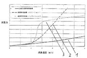
図1内で連続線を用いて描かれた、ピストン速度に対する減衰力経過の第1特性曲線バリエーション1は、従来技術による自動車(モータビークル)の車輪懸架装置用の振動減衰方法により生成されている。自動車用、特に乗用車用の減衰力調整時、快適性と走行安全性に目を向けるとピストン速度のほぼ1m/s〜2m/sまでの減衰力特性曲線が考察される。2m/sよりも大きい減衰力特性に対しては、通常、従来技術により、ピストン/バルブ・コンビネーションから最大でも極めて僅かに累進的な上昇だけが得られる。このことは、普通、車台設計時に甘受される。
The first
例えば障害物のある道路を走行する場合や隆起のある道路を走行する場合に発生するように、2m/sよりも大きく車輪の垂直方向(上下方向)速度が極めて大きい場合、加速されたスプリング荷重のかからない質量体により、エンドストッパ領域内で車体(ボディー)及び車台(シャシー)に極端に大きな負荷が発生する。 For example, when running on roads with obstacles or on roads with bumps, if the wheel vertical speed (vertical direction) is much higher than 2 m / s, the accelerated spring load Due to the mass body that is not applied, an extremely large load is generated on the vehicle body (body) and chassis (chassis) in the end stopper region.
このことは、関与する構造コンポーネントにおいて、極端に中実であり補強され、従って重く高価となる設計をもたらす。このように大きい加速度のための減衰力は、従来技術による通例の減衰器では小さすぎ、このことは、主エネルギーが車体構造により支持されなくてはならないことを意味する。 This results in a design that is extremely solid and reinforced in the structural components involved, and thus heavy and expensive. The damping force for such a large acceleration is too small for a conventional attenuator according to the prior art, which means that the main energy must be supported by the vehicle body structure.
それ故、本発明は、弁の適切な選択、構成、設計を介し、又は液圧抵抗のその他の影響を介し、特性曲線2、3が実現される振動減衰方法を提案する。この際、それらの特性曲線は、今まで通例どおり考察されていたほぼ2m/sまでのピストン速度範囲内では実質的に今まで通例の減衰力を生成する。ほぼ2m/sよりも大きな速度以降にだけ、特性曲線1と比べ、加速された質量をより強く減速するために、減衰力特性曲線2、3内では極端な累進性(非線形性)が発生する。
Therefore, the present invention proposes a vibration damping method in which the
鎖線で描かれている特性曲線2と、点線で描かれている特性曲線3とは、例として、液圧式の振動減衰器を用いた自動車用車輪懸架装置における本発明に従う振動減衰方法のための選択肢である。これらの選択肢は、振動減衰器の減衰力が、ピストン速度に依存し、特に実質的に0m/s〜2m/sのピストン速度の範囲内で最初はゆっくりと実質的に直線的に(リニア:線形で)上昇し、その後、特に実質的に2m/sのピストン速度以降では実質的に強く累進的に(プログレッシブ:非線形で)上昇することにより特徴付けられている。特性曲線2は、ほぼ2m/s〜3m/sにおける累進的な経過の後、更に実質的に直線的に上昇する。特性曲線3は、ほぼ2m/s〜2.5m/sにおける強い累進的な上昇の後、2.5m/s〜3m/sの範囲内で、再び、僅かに上昇する実質的に直線的な経過に移行している。
The
それにより質量体の加速度並びに車体及び車台の負荷が減少される。より容易でより安価な車体設計、車台設計、車両設計が可能である。このことは特に、例えばスポーツシャシーや極めて僅かな最低地上高を有する車両などのような僅かなバネ行程を有する車両において有利である。車両の寿命がより長くなること、及び、極端な悪路時に車体構造の損傷がより少なくなることが達成される。 Thereby, the acceleration of the mass body and the load on the vehicle body and the chassis are reduced. Easier and cheaper car body design, chassis design, and vehicle design are possible. This is particularly advantageous in vehicles having a slight spring travel, such as for example a sports chassis or a vehicle having a very low minimum ground clearance. A longer vehicle life and less damage to the vehicle structure during extreme bad roads are achieved.
本発明に従うそのような特性曲線経過は、例えば、調整弁を介して慣性力制御式である振動減衰器を用いても実現され得る。その際、同じ振動減衰器を用い、図2に描かれている、ピストン速度に対する様々な減衰力経過の特性曲線バリエーションが、調整弁に対する慣性力作用に依存して進行され得る。異なる慣性力のための様々な4つの特性曲線が、重力加速度の一部分をもとに描かれて記入されている。全ての特性曲線は、本発明に従い、振動減衰器の減衰力がピストン速度に依存して最初はゆっくりと実質的に直線的で上昇し、その後、所定のピストン速度以降は実質的に強く累進的に上昇するという振動減衰のための方法を実現している。その際、これらの特性曲線は、急勾配で実質的に直線的な上昇をもって経過してゆき、その後、実質的に直線的で僅かに上昇してゆく経過へと移行している。4つの全ての特性曲線において、強く累進的な上昇の開始は、まだ快適性にとって重要な範囲内のピストン速度のところに位置する。振動減衰器の慣性力制御式の調節装置により、ピストン速度に依存する減衰力の特性曲線が、図示されているように実質的に横座標4に沿ってシフトされる。
Such a characteristic curve course according to the invention can also be realized, for example, using a vibration attenuator that is of inertial force control via a regulating valve. In this case, using the same vibration attenuator, the characteristic curve variations of the various damping force courses with respect to the piston speed depicted in FIG. 2 can be advanced depending on the inertial force action on the regulating valve. Various four characteristic curves for different inertial forces are drawn and filled based on a portion of gravitational acceleration. All characteristic curves are in accordance with the present invention, in which the damping force of the vibration attenuator is initially slowly and substantially linearly dependent on the piston speed, and then substantially strongly and progressively after a given piston speed. A method for vibration damping that rises to a high level is realized. At that time, these characteristic curves have progressed with a steep and substantially linear rise, and then a substantially linear and slightly rising course. In all four characteristic curves, the onset of strong progressive rise is still at a piston speed within a range important for comfort. Due to the inertial force-controlled adjusting device of the vibration damper, the characteristic curve of the damping force depending on the piston speed is shifted substantially along the
1 第1の減衰力特性曲線(従来技術による)
2 第2の減衰力特性曲線(本発明による)
3 第3の減衰力特性曲線(本発明による)
4 横座標(減衰速度)
1 First damping force characteristic curve (according to the prior art)
2 Second damping force characteristic curve (according to the invention)
3 Third damping force characteristic curve (according to the invention)
4 abscissa (damping speed)
Claims (4)
Applications Claiming Priority (2)
| Application Number | Priority Date | Filing Date | Title |
|---|---|---|---|
| DE10347219A DE10347219A1 (en) | 2003-10-10 | 2003-10-10 | Method for vibration damping |
| PCT/EP2004/052337 WO2005037581A1 (en) | 2003-10-10 | 2004-09-28 | Vibration damping method |
Publications (1)
| Publication Number | Publication Date |
|---|---|
| JP2007508501A true JP2007508501A (en) | 2007-04-05 |
Family
ID=34428310
Family Applications (1)
| Application Number | Title | Priority Date | Filing Date |
|---|---|---|---|
| JP2006530255A Pending JP2007508501A (en) | 2003-10-10 | 2004-09-28 | Method for vibration damping |
Country Status (5)
| Country | Link |
|---|---|
| US (1) | US8757333B2 (en) |
| EP (1) | EP1569810B1 (en) |
| JP (1) | JP2007508501A (en) |
| DE (2) | DE10347219A1 (en) |
| WO (1) | WO2005037581A1 (en) |
Families Citing this family (17)
| Publication number | Priority date | Publication date | Assignee | Title |
|---|---|---|---|---|
| US10900539B2 (en) | 2005-12-30 | 2021-01-26 | Fox Factory, Inc. | Fluid damper having a damping profile favorable for absorbing the full range of compression forces, including low- and high-speed compression forces |
| US8457841B2 (en) | 2007-08-31 | 2013-06-04 | GM Global Technology Operations LLC | Suspension system with optimized damping response |
| US8428819B2 (en) | 2007-08-31 | 2013-04-23 | GM Global Technology Operations LLC | Suspension system with optimized damper response for wide range of events |
| US8439173B2 (en) * | 2008-09-25 | 2013-05-14 | GM Global Technology Operations LLC | Methods and apparatus for a suspension system with progressive resistance |
| DE102010045114B4 (en) | 2010-09-13 | 2019-12-19 | Grammer Aktiengesellschaft | Method for operating a vehicle damping device for a vehicle seat / a vehicle cabin and vehicle damping device for a vehicle seat / a vehicle cabin |
| DE102010048210B4 (en) | 2010-10-13 | 2021-09-16 | Grammer Aktiengesellschaft | Vehicle seat with fluid spring |
| DE102010051325B4 (en) | 2010-11-16 | 2020-11-26 | Grammer Aktiengesellschaft | Seat base for a person seat |
| DE102010055344A1 (en) | 2010-12-21 | 2012-06-21 | Grammer Aktiengesellschaft | Horizontal seat adjustment with actuator |
| DE102011009530B4 (en) | 2011-01-26 | 2014-04-10 | Grammer Aktiengesellschaft | Vehicle vibration device, vehicle seat or passenger compartment or vehicle cabin of a vehicle |
| DE102011015364B4 (en) | 2011-03-28 | 2012-10-11 | Grammer Aktiengesellschaft | Vehicle seat with a support structure |
| US8918253B2 (en) | 2012-06-25 | 2014-12-23 | Ford Global Technologies, Llc | Ride performance optimization in an active suspension system |
| US9738132B2 (en) | 2012-06-25 | 2017-08-22 | Ford Global Technologies, Llc | Ride performance optimization in an active suspension system |
| DE102014204519A1 (en) * | 2013-04-08 | 2014-10-09 | Ford Global Technologies, Llc | Apparatus and method for proactively controlling a vibration damping system of a vehicle |
| DE102015205369B4 (en) | 2014-04-04 | 2019-08-22 | Ford Global Technologies, Llc | Method for operating a suspension system |
| DE102015200444A1 (en) * | 2015-01-14 | 2016-07-14 | Zf Friedrichshafen Ag | Vibration damper, motor vehicle and method for vibration damping on a vehicle wheel suspension |
| US10160447B2 (en) | 2015-10-20 | 2018-12-25 | Ford Global Technologies, Llc | Systems and methods for abrupt road change assist and active suspension control |
| US10737544B2 (en) * | 2017-07-24 | 2020-08-11 | Ford Global Technologies, Llc | Systems and methods to control a suspension of a vehicle |
Citations (2)
| Publication number | Priority date | Publication date | Assignee | Title |
|---|---|---|---|---|
| JPS58211044A (en) * | 1982-05-31 | 1983-12-08 | Kayaba Ind Co Ltd | Shock absorber and control method of its damping force |
| DE9402417U1 (en) * | 1994-02-15 | 1994-04-07 | Showa Corp | Hydraulic damper |
Family Cites Families (21)
| Publication number | Priority date | Publication date | Assignee | Title |
|---|---|---|---|---|
| FR1467818A (en) | 1965-12-07 | 1967-02-03 | Citroen Sa Andre | Advanced hydraulic shock absorber with communication spool for motor vehicles or others |
| DE1967943U (en) | 1965-12-22 | 1967-09-07 | Hoesch Ag | SHOCK PISTON EQUIPPED WITH A FORCE LIMITING VALVE. |
| US3704767A (en) * | 1967-12-11 | 1972-12-05 | Tatsuya Takagi | Oil-type vibration damper |
| DE2022021A1 (en) | 1969-05-08 | 1970-11-12 | Simca Automobiles Sa | Hydraulic telescopic shock absorber |
| FR2041630A5 (en) | 1969-05-08 | 1971-01-29 | Simca Automobiles Sa | |
| JPS52113477A (en) | 1976-03-19 | 1977-09-22 | Tokico Ltd | Oil hydraulic buffer |
| DE3120016A1 (en) * | 1981-05-20 | 1982-12-09 | Stabilus Gmbh, 5400 Koblenz | SHOCK ABSORBER WITH SPEED-RELATED DAMPER DEVICE |
| US4809828A (en) * | 1987-07-01 | 1989-03-07 | Kabushiki Kaisha Showa Seisakusho | One-way damping valve mechanism for hydraulic damper |
| DE3729187C2 (en) * | 1987-09-01 | 1995-01-26 | Rexroth Mannesmann Gmbh | Adjustable cushioning |
| US5107969A (en) * | 1987-09-17 | 1992-04-28 | Alfred Teves Gmbh | Controllable vibration damper |
| DE3813402C2 (en) | 1988-04-21 | 1998-04-09 | Stabilus Gmbh | Damping valves with speed-dependent - highly progressive damping force |
| DE4403196C2 (en) | 1993-02-17 | 1999-06-17 | Mannesmann Sachs Ag | Vibration damper with a damping force map as required |
| FR2701745B1 (en) * | 1993-02-17 | 1998-02-13 | Fichtel & Sachs Ag | Vehicle fitted with a shock absorber with variable characteristics, and shock absorber for such a vehicle. |
| JP3471438B2 (en) * | 1993-12-06 | 2003-12-02 | 株式会社ショーワ | Shock absorber valve structure |
| US6102170A (en) * | 1998-05-07 | 2000-08-15 | Tenneco Automotive Inc. | Passive anti-roll system |
| JP2000186734A (en) * | 1998-12-22 | 2000-07-04 | Kayaba Ind Co Ltd | Adjusting structure of damping force |
| JP2001208123A (en) * | 2000-01-21 | 2001-08-03 | Yamaha Motor Co Ltd | Hydraulic buffer |
| FR2804188B1 (en) * | 2000-01-26 | 2002-05-03 | Dld Internat | HIGH DISSIPATIVE SHOCK ABSORBER |
| DE10105098C1 (en) * | 2001-02-05 | 2002-10-10 | Zf Sachs Ag | Vibration damper with overload protection |
| CA2373398A1 (en) * | 2001-02-26 | 2002-08-26 | Bombardier Inc. | Shock absorber adjustable in compression |
| JP2006507449A (en) * | 2002-01-11 | 2006-03-02 | アクティブ・ショック・インコーポレイテッド | Semi-active shock absorber control system |
-
2003
- 2003-10-10 DE DE10347219A patent/DE10347219A1/en not_active Withdrawn
-
2004
- 2004-09-28 EP EP04766859A patent/EP1569810B1/en active Active
- 2004-09-28 WO PCT/EP2004/052337 patent/WO2005037581A1/en active IP Right Grant
- 2004-09-28 JP JP2006530255A patent/JP2007508501A/en active Pending
- 2004-09-28 DE DE502004001337T patent/DE502004001337D1/en active Active
-
2006
- 2006-04-07 US US11/399,638 patent/US8757333B2/en active Active
Patent Citations (2)
| Publication number | Priority date | Publication date | Assignee | Title |
|---|---|---|---|---|
| JPS58211044A (en) * | 1982-05-31 | 1983-12-08 | Kayaba Ind Co Ltd | Shock absorber and control method of its damping force |
| DE9402417U1 (en) * | 1994-02-15 | 1994-04-07 | Showa Corp | Hydraulic damper |
Also Published As
| Publication number | Publication date |
|---|---|
| US20060243548A1 (en) | 2006-11-02 |
| WO2005037581A1 (en) | 2005-04-28 |
| EP1569810B1 (en) | 2006-08-30 |
| EP1569810A1 (en) | 2005-09-07 |
| DE502004001337D1 (en) | 2006-10-12 |
| DE10347219A1 (en) | 2005-05-12 |
| US8757333B2 (en) | 2014-06-24 |
Similar Documents
| Publication | Publication Date | Title |
|---|---|---|
| US8757333B2 (en) | Vibration damping method | |
| US8457841B2 (en) | Suspension system with optimized damping response | |
| US8632078B2 (en) | Vehicle with a leaf spring element for the spring suspension of the vehicle | |
| JP2005119548A (en) | Suspension device of electric vehicle | |
| KR100709011B1 (en) | Method for controlling damper of cars | |
| JP5001585B2 (en) | Control device for variable damping force damper | |
| KR102185228B1 (en) | Height adjustable suspension with MR Damper | |
| CN202156256U (en) | Cushioning device for automobile chassis | |
| JP4546323B2 (en) | Variable damping force damper | |
| KR101881157B1 (en) | Cargo deflection prevention system of cargo truck using mr damper | |
| KR20050118405A (en) | System for control diminishing force of shock absorber | |
| JP4621582B2 (en) | Control device for variable damping force damper | |
| EP2607116A1 (en) | Motor-vehicle with a rear shock-absorber having a differentiated effect, for controlling the vehicle attitude during braking, and control method used therein | |
| JP2009040386A (en) | Turning posture control device for automobile | |
| JP2007046733A (en) | Upper mount | |
| CN109070677B (en) | Hydraulic suspension system for vehicle | |
| EP1959155B1 (en) | A dissipation method of impact hydraulic damper loadings | |
| KR102109216B1 (en) | Step bar device for suspension of vehicle | |
| JP2006273225A (en) | Controlling device for adjustable damping force damper | |
| WO2021157640A1 (en) | Vehicle control device, vehicle control method, and vehicle control system | |
| JP4987762B2 (en) | Control device for damping force variable damper | |
| KR100204902B1 (en) | Anti-dive device for vehicle | |
| CN117656738A (en) | Control system of suspension assembly and vehicle | |
| JP2024006248A (en) | damper | |
| JP2006321260A (en) | Adjustable damper |
Legal Events
| Date | Code | Title | Description |
|---|---|---|---|
| A621 | Written request for application examination |
Free format text: JAPANESE INTERMEDIATE CODE: A621 Effective date: 20070913 |
|
| A977 | Report on retrieval |
Free format text: JAPANESE INTERMEDIATE CODE: A971007 Effective date: 20100730 |
|
| A131 | Notification of reasons for refusal |
Free format text: JAPANESE INTERMEDIATE CODE: A131 Effective date: 20100914 |
|
| A02 | Decision of refusal |
Free format text: JAPANESE INTERMEDIATE CODE: A02 Effective date: 20110301 Free format text: JAPANESE INTERMEDIATE CODE: A02 Effective date: 20110301 |