JP2007508183A - Vehicle wheel rim and method of manufacturing the same - Google Patents
Vehicle wheel rim and method of manufacturing the same Download PDFInfo
- Publication number
- JP2007508183A JP2007508183A JP2006534534A JP2006534534A JP2007508183A JP 2007508183 A JP2007508183 A JP 2007508183A JP 2006534534 A JP2006534534 A JP 2006534534A JP 2006534534 A JP2006534534 A JP 2006534534A JP 2007508183 A JP2007508183 A JP 2007508183A
- Authority
- JP
- Japan
- Prior art keywords
- rim
- core
- vehicle wheel
- support member
- tire
- Prior art date
- Legal status (The legal status is an assumption and is not a legal conclusion. Google has not performed a legal analysis and makes no representation as to the accuracy of the status listed.)
- Pending
Links
Images


Classifications
-
- B—PERFORMING OPERATIONS; TRANSPORTING
- B60—VEHICLES IN GENERAL
- B60B—VEHICLE WHEELS; CASTORS; AXLES FOR WHEELS OR CASTORS; INCREASING WHEEL ADHESION
- B60B5/00—Wheels, spokes, disc bodies, rims, hubs, wholly or predominantly made of non-metallic material
- B60B5/02—Wheels, spokes, disc bodies, rims, hubs, wholly or predominantly made of non-metallic material made of synthetic material
-
- B—PERFORMING OPERATIONS; TRANSPORTING
- B60—VEHICLES IN GENERAL
- B60B—VEHICLE WHEELS; CASTORS; AXLES FOR WHEELS OR CASTORS; INCREASING WHEEL ADHESION
- B60B21/00—Rims
- B60B21/02—Rims characterised by transverse section
- B60B21/025—Rims characterised by transverse section the transverse section being hollow
-
- B—PERFORMING OPERATIONS; TRANSPORTING
- B60—VEHICLES IN GENERAL
- B60B—VEHICLE WHEELS; CASTORS; AXLES FOR WHEELS OR CASTORS; INCREASING WHEEL ADHESION
- B60B21/00—Rims
- B60B21/02—Rims characterised by transverse section
- B60B21/04—Rims characterised by transverse section with substantially radial flanges
-
- B—PERFORMING OPERATIONS; TRANSPORTING
- B60—VEHICLES IN GENERAL
- B60B—VEHICLE WHEELS; CASTORS; AXLES FOR WHEELS OR CASTORS; INCREASING WHEEL ADHESION
- B60B21/00—Rims
- B60B21/06—Rims characterised by means for attaching spokes, i.e. spoke seats
- B60B21/062—Rims characterised by means for attaching spokes, i.e. spoke seats for bicycles
-
- B—PERFORMING OPERATIONS; TRANSPORTING
- B60—VEHICLES IN GENERAL
- B60Y—INDEXING SCHEME RELATING TO ASPECTS CROSS-CUTTING VEHICLE TECHNOLOGY
- B60Y2200/00—Type of vehicle
- B60Y2200/10—Road Vehicles
- B60Y2200/13—Bicycles; Tricycles
-
- Y—GENERAL TAGGING OF NEW TECHNOLOGICAL DEVELOPMENTS; GENERAL TAGGING OF CROSS-SECTIONAL TECHNOLOGIES SPANNING OVER SEVERAL SECTIONS OF THE IPC; TECHNICAL SUBJECTS COVERED BY FORMER USPC CROSS-REFERENCE ART COLLECTIONS [XRACs] AND DIGESTS
- Y10—TECHNICAL SUBJECTS COVERED BY FORMER USPC
- Y10T—TECHNICAL SUBJECTS COVERED BY FORMER US CLASSIFICATION
- Y10T29/00—Metal working
- Y10T29/49—Method of mechanical manufacture
- Y10T29/49481—Wheel making
- Y10T29/49492—Land wheel
- Y10T29/49524—Rim making
Abstract
乗物用ホイールのリム(1)は、リム底(2)と該リム底(2)の横方向の両端に形成されたリムフランジ(3)とが一体化された単一部材として形成され、タイヤ(5)の支持部材(7)を受けるための合成繊維材料からなるリムベースを備えている。さらに、製造工程を簡略化し、かつひずみ耐性を向上させるために、リム(1)は、コア(13)から単一部材として形成され、タイヤ(5)の支持部材(7)を受けて支えるための対向支持部材(8)を備え、対向支持部材(8)は、前記リムベースにおけるタイヤ(5)の支持部材(7)を受ける面の形状に合致するように機械加工され、該リムベースに強固に固定されている。 A rim (1) of a vehicle wheel is formed as a single member in which a rim bottom (2) and rim flanges (3) formed at both lateral ends of the rim bottom (2) are integrated. A rim base made of a synthetic fiber material for receiving the support member (7) of (5) is provided. Furthermore, in order to simplify the manufacturing process and improve the strain resistance, the rim (1) is formed as a single member from the core (13) and receives and supports the support member (7) of the tire (5). The opposing support member (8) is machined to match the shape of the surface of the rim base that receives the support member (7) of the tire (5), and is firmly attached to the rim base. It is fixed.
Description
本発明は、ホイールが装着される自転車等の乗物用ホイールのリム、特に、タイヤの支持部材を受けるための合成繊維材料からなる部材であって、リム底と該リム底の横方向の両側に形成されたリムフランジとが一体化されて単一部材として形成されたリムベースを備えた乗物用ホイールのリムおよびその製造方法に関するものである。 The present invention relates to a rim for a vehicle wheel such as a bicycle to which the wheel is mounted, in particular, a member made of a synthetic fiber material for receiving a tire support member, on the rim bottom and both lateral sides of the rim bottom. The present invention relates to a vehicle wheel rim including a rim base formed integrally with a formed rim flange and a manufacturing method thereof.
リムに装着されたタイヤは、その内部圧力によりリムフランジに大きなひずみをもたらすことがある。特に、タイヤの内部圧力が非常に高くなる高性能の自転車については、特に上記のひずみが大きくなる。このようなリムの製造工程は非常に複雑であり、上記のリムの特徴を考慮した理想的な繊維の配向を有するリム、特にタイヤの静圧下で十分な疲労強度を有するリムは、未だ実現できていない。 A tire mounted on a rim may cause a large strain on the rim flange due to its internal pressure. In particular, the above-mentioned distortion becomes large especially for a high-performance bicycle in which the internal pressure of the tire is very high. The manufacturing process of such a rim is very complicated, and a rim having an ideal fiber orientation considering the characteristics of the rim described above, particularly a rim having sufficient fatigue strength under the static pressure of a tire, has not been realized yet. Not.
US特許公開公報2002/0108249および国際公開公報02/26510に、上記のコアの製造方法としていわゆる折り畳み式コアを用いた技術(collapsible core technique)が開示されている。具体的には、上記折り畳み式コアをリム底とリムフランジとの間にセットした状態でリム部材(rim blank)をリム鋳造金型にセットし、リム部材を加熱することによって、上記折り畳み式コアがリム底とリムフランジとで形成される空間部の形状を定めるように構成されている。しかしながら、上記の方法は、時間と費用を要する点において不利益である。これは、リムの外周を横切る方向に延びるように形成しなければならない折り畳み式コアを、径方向に分割するだけでなく、リムレベルでも分割して、リムを硬化した後、取り外して再利用できるようにしなければならないためである。 US Patent Publication No. 2002/0108249 and International Publication No. 02/26510 disclose a technique using a so-called foldable core (collapsible core technique) as a method of manufacturing the above-described core. Specifically, the foldable core is set by heating the rim member by setting a rim member (rim blank) in a rim casting mold while the foldable core is set between the rim bottom and the rim flange. Is configured to define the shape of the space formed by the rim bottom and the rim flange. However, the above method is disadvantageous in that it requires time and cost. This means that the collapsible core, which must be formed to extend in the direction across the outer circumference of the rim, is not only divided in the radial direction, but also at the rim level so that the rim can be hardened and then removed and reused. This is because it must be done.
ここで加熱工程の前に、鋳造金型に複数ピースからなるコアを並べてセットし、過熱工程の後に鋳造金型から取り出す作業は、複雑な手作業を伴い熟練を要する。特に、上記の折り畳み式コアを構成するパーツは、断面が小さい一方、比較的長く形成されているため、もろく、不良品の発生率が高くなるといった問題がある。 Here, the work of setting a plurality of cores side by side on the casting mold before the heating process and taking out the core from the casting mold after the heating process is complicated and requires skill. In particular, the parts constituting the foldable core have a problem that the cross section is small, but they are formed relatively long, so that they are fragile and have a high incidence of defective products.
US特許公開公報2002/0108249は、単一部材からなるコアも開示している。しかしながら、単一部材からなるコアは、リムを硬化させた後、リムフランジとリム底とで形成された空間から取り出せるように、柔軟性を備える必要がある。すなわち、リムを硬化させた後、好ましくはシリコンからなるコアを特殊なペンチを用いて取り出す必要があり、その際に完成したリムが損傷する場合がしばしばある。 US Patent Publication 2002/0108249 also discloses a core made of a single member. However, the core made of a single member needs to have flexibility so that it can be taken out of the space formed by the rim flange and the rim bottom after the rim is cured. That is, after the rim has been cured, it is necessary to remove the core, preferably made of silicon, using special pliers, often resulting in damage to the completed rim.
また、US特許公開公報2002/0108249のコアは、その断面形状における設計上の自由度が低く、リムの丸くなった角またはエッジ部分、特に、リム底とリムフランジのつなぎ部分の領域の設計上の制限のため、十分に負荷に耐え得る形状とすることができないといった問題がある。 Further, the core of US Patent Publication No. 2002/0108249 has a low degree of design freedom in its cross-sectional shape, and the design of the rounded corner or edge portion of the rim, particularly the region between the rim bottom and the rim flange. For this reason, there is a problem that the shape cannot sufficiently withstand the load.
AT特許公報401639は、前述した構造のリムを開示している。すなわち、AT特許公報40169のリムは、隔壁で仕切られ充填材が入れられた2つの区画を備え、径方向外側の区画が外部に通じている構成となっている。ここでは、注入されたフォームが上記外側の区画の充填材として機能する。 AT Patent Publication 401639 discloses a rim having the structure described above. That is, the rim of AT Patent Publication 40169 has two compartments partitioned by a partition wall and filled with a filler, and the radially outer compartment communicates with the outside. Here, the injected foam functions as a filler for the outer compartment.
上記の問題点に鑑み、本発明の目的は、正確、簡単かつ極めて安全に製造することができる自転車等の乗物用のホイールのリムを提供することにある。本発明の製造方法によれば、従来のリムの製造方法に比べて、製造に要する時間を大幅に短縮することができる。さらに、十分な負荷耐性を有するリムをコストの増加を伴うことなく製造することができる。また、本発明の製造方法によれば、各工程を安定して実施することができ、生産性の向上を図ることができる。また、競技用自転車のリムは、特に軽量化が求められるため、競技用自転車のリムの特性としては、軽量であって強度が高いことが重要であり、例えば、高強度のワイヤスポークを要することなく、高いタイヤ圧力にも耐え得る強度が要求される。 In view of the above problems, an object of the present invention is to provide a wheel rim for a vehicle such as a bicycle that can be manufactured accurately, simply and extremely safely. According to the manufacturing method of the present invention, the time required for manufacturing can be greatly reduced as compared with the conventional manufacturing method of rims. Furthermore, a rim having sufficient load resistance can be manufactured without increasing costs. Moreover, according to the manufacturing method of this invention, each process can be implemented stably and productivity can be aimed at. In addition, since the weight of the rim of the competition bicycle is particularly required, it is important that the rim of the competition bicycle is lightweight and strong, for example, it requires high-strength wire spokes. In addition, the strength is required to withstand high tire pressure.
上記の課題を解決するために、本発明の自転車を含む乗物用ホイールのリムは、リムベースで形成された領域内に埋め込まれたコアから単一部材として形成された部材であって、タイヤの支持部材を受けて支えるための対向支持部材を備え、前記対向支持部材が、前記リムベースにおけるタイヤの支持部材を受ける面の形状に合致するように機械加工され、該リムベースに強固に固定されていることを特徴とする。 In order to solve the above problems, a rim of a vehicle wheel including a bicycle according to the present invention is a member formed as a single member from a core embedded in a region formed by a rim base, and supports a tire. An opposing support member for receiving and supporting the member is provided, and the opposing support member is machined to match the shape of the surface of the rim base that receives the tire support member, and is firmly fixed to the rim base. It is characterized by.
上記の構成によれば、前記リムベースに強固に固定された対向支持部材により、簡単に、リムの断面形状を、所望の負荷耐性が得られる断面形状とすることができる。また、タイヤが装着された状態では、装着されたタイヤが前記対向支持部材によって支持される。したがって、リムフランジの設計上の自由度が高くなる。このため、リムフランジに負荷が集中するといった問題を回避することができ、リムフランジを適切に機能し得る形状とすることができる。 According to said structure, the cross-sectional shape of a rim can be easily made into the cross-sectional shape from which desired load tolerance is acquired with the opposing support member fixed firmly to the said rim base. Further, in the state where the tire is mounted, the mounted tire is supported by the opposing support member. Therefore, the design freedom of the rim flange is increased. For this reason, the problem that a load concentrates on a rim flange can be avoided, and the rim flange can be formed into a shape that can function appropriately.
さらに、コアを再使用を予定しない単一部材として設計することができ、かつ取り扱いを容易とするために十分な剛度および強度を備えることができる。 Furthermore, the core can be designed as a single member that is not intended for reuse and can have sufficient rigidity and strength to facilitate handling.
本発明のリムは、前記対向支持部材が、前記リム底上および前記リムフランジ上に形成されており、前記タイヤが装着された状態で、前記タイヤの前記支持部材、リム底およびリムフランジで形成される空間を埋めるように形成されており、さらに、前記リム底が、前記ホイールのハブに向かって凸状に形成されており、前記リム底の外側表面が前記リムフランジの外側表面と連続した曲面を形成するように、該リムフランジと一体的に形成されていることが望ましい。 In the rim of the present invention, the opposing support member is formed on the rim bottom and the rim flange, and is formed by the support member, the rim bottom and the rim flange of the tire when the tire is mounted. The rim bottom is formed in a convex shape toward the hub of the wheel, and the outer surface of the rim bottom is continuous with the outer surface of the rim flange. It is desirable to form integrally with the rim flange so as to form a curved surface.
また、強度を考えた場合、前記リム底と前記リムフランジとが一体化されて形成される単一部材の断面形状が楕円形または長円形の一部をなすことが望ましい。 In view of strength, it is preferable that the cross-sectional shape of a single member formed by integrating the rim bottom and the rim flange is part of an ellipse or an oval.
大きいひずみに対しては、以下のように構成することが望ましい。すなわち、前記リム底に、前記ホイールのハブ方向に形成されたキャビティが連結されており、該キャビティは、該リム底と合成繊維材料からなる部材が一体化された外枠を有し、前記外枠を構成する部材は、前記キャビティの両側面を含み、該両側面は、凹凸を形成することなく前記リムフランジと連続して形成されている構成することが望ましい。 For large strains, the following configuration is desirable. That is, a cavity formed in the hub direction of the wheel is connected to the rim bottom, and the cavity has an outer frame in which a member made of a synthetic fiber material is integrated with the rim bottom, The member constituting the frame preferably includes both side surfaces of the cavity, and the both side surfaces are formed continuously with the rim flange without forming irregularities.
また、前記対向支持部材を形成するためのコアの材料としては、熱可塑性材料、熱硬化性材料、天然素材または天然素材を加工した材料を用いることができ、さらに、充填剤を含み、該充填剤が、金属、有機材料または天然鉱物からなることが望ましい。 Further, as the core material for forming the opposed support member, a thermoplastic material, a thermosetting material, a natural material or a material obtained by processing a natural material can be used, and further includes a filler, Desirably, the agent comprises a metal, an organic material or a natural mineral.
本発明のリムの製造方法は、リムベースの成形に用いるコアの材料が充填され、リムを所望の断面形状に成形するための鋳造金型に、リム底と該リム底の横方向の両端に形成されたリムフランジとから形成され、合成繊維材料からなるリムベースを備えたリム部材をはめ込み、該リム部材の材料を硬化する硬化工程を含む乗物用ホイールのリムの製造方法において、前記リム部材を鋳造金型にはめ込む前に、前記リム底と前記リムフランジとによって形成された空間を埋めるようにデッドコアを充填する工程と、前記硬化工程の後に、前記コアを機械加工して、タイヤの支持部材を受けて支持する対向支持部材を形成する工程とを含むことを特徴としている。 The rim manufacturing method of the present invention is formed in a casting mold for forming a rim into a desired cross-sectional shape, which is filled with a core material used for molding a rim base, and formed at both ends of the rim bottom and the rim bottom in the lateral direction. In a method for manufacturing a rim for a vehicle wheel, including a curing step of fitting a rim member having a rim base made of a synthetic fiber material and curing the material of the rim member, the rim member is cast. Before inserting into the mold, filling the dead core so as to fill the space formed by the rim bottom and the rim flange; and after the curing step, machining the core to provide a tire support member And a step of forming an opposing support member to be received and supported.
前記コアを機械加工する場合、リムフランジのエッジも機械加工することが望ましい。 When machining the core, it is also desirable to machine the edge of the rim flange.
また、前記リム底および前記リムフランジに制限されるリム部材の内側に、前記コアを前記リム部材に接着するための樹脂を挿入する工程とを含み、前記樹脂は、前記内側がコアに接触している状態で、液体であることが望ましい。 And inserting a resin for bonding the core to the rim member inside the rim member restricted to the rim bottom and the rim flange, the resin contacting the core on the inner side. In this state, it is desirable to be a liquid.
前記コアの材料として合成材料を用い、該合成材料の表面を化学的に活性させて、接着性を強化することが望ましい。また、火炎処理(flame treatment)および/または荒加工処理(roughening)および/またはケミカルエッチングおよび/またはコア表面のコロナ処理により、前記合成材料の表面を活性化させることが望ましい。 It is desirable to use a synthetic material as the material of the core and chemically activate the surface of the synthetic material to enhance the adhesion. It is also desirable to activate the surface of the synthetic material by flame treatment and / or roughening and / or chemical etching and / or corona treatment of the core surface.
以下に本発明の例示的な実施の形態について詳細に説明する。 Hereinafter, exemplary embodiments of the present invention will be described in detail.
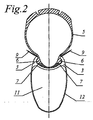
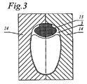
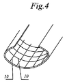
図1は、自転車、特に競技用自転車用に設計されたリムの断面図である。図2は、上記リムにタイヤを装着した状態を示す断面図である。図3は、リム部材をはめ込んだ状態のリム鋳造金型の断面図である。図4は、タイヤのトレッドプライに埋め込む繊維の配向の一例を示す説明図である。図5は、タイヤのトレッドプライに埋め込む繊維の他の配向例を示す説明図である。図6は、タイヤのトレッドプライに埋め込む繊維のさらに他の配向例を示す説明図である。 FIG. 1 is a cross-sectional view of a rim designed for a bicycle, particularly a racing bicycle. FIG. 2 is a cross-sectional view showing a state where a tire is mounted on the rim. FIG. 3 is a cross-sectional view of the rim casting mold with the rim member fitted therein. FIG. 4 is an explanatory view showing an example of the orientation of fibers embedded in a tread ply of a tire. FIG. 5 is an explanatory view showing another example of orientation of fibers embedded in a tread ply of a tire. FIG. 6 is an explanatory view showing still another example of orientation of fibers embedded in a tread ply of a tire.
本発明のリムは、上記自転車以外の乗物、例えば、モータ駆動の乗物にも適用できる。 The rim of the present invention can be applied to a vehicle other than the bicycle, for example, a motor-driven vehicle.
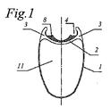
図1に示すように、本実施の形態に係るリム1は、リム底2とリム底2の横方向の両端に形成されたリムフランジ3とを備えている。リムフランジ3は、それぞれ径方向外側に突き出ている。2つのリムフランジ3とリム底2とに囲まれた空間4には、タイヤトレッド6を備えたタイヤ5がはめ込まれる。このように、タイヤ5が装着された状態で、対向支持部材8が、タイヤ5の支持部材7を受けて支えるように構成されている。対向支持部材8は、リム底2とリムフランジ3とによって構成されるリムベースの形状に合致するように形成され、該リムベースに強固に固定されている。また、ダイヤブレッド6は、対向支持部材8によって完全に支持される。
As shown in FIG. 1, the
上記の構成の対向支持部材8を備えたリム1は、リム底2を強い弓状に形成することができる。ここで、リム底2は、リムフランジ3と一体化しており、その断面が楕円の一部を構成するように形成されていることが望ましい。また、リムフランジ3は、凹凸を形成することなくスムースにリム底2と一体化して形成されていることが望ましい。
The
リム1は、合成繊維材料から形成されており、対向支持部材8を備えることにより、リム底2の断面を、タイヤの圧力により生じる力(図2中、矢印9で示す)を考慮して、最適に形成することができる。図4、図5および図6に示すように、タイヤ5の材料である合成繊維材料の繊維クロスプライ(fibre cross-plies)10は、円周方向に延びるように形成してもよいし、横方向に延びるように形成されていてもよい(図4)。また、繊維クロスプライ10は、交差するように配向されていてもよく、さらに交差するように配向された繊維が層状に形成されていてもよい(図5、図6)。
The
図1に示すように、リム底2には、ホイールハブ(図示せず)の方向に形成されたキャビティ11が連結されており、該キャビティ11は、該リム底2と合成繊維材料からなる部材が一体化された外枠を有し、該外枠を構成する部材は、キャビティ11の両側面12を含み、該両側面12は、凹凸を形成することなくリムフランジ3と連続して形成されている。
As shown in FIG. 1, a
次に、本実施の形態にかかるリム1の製造方法について説明する。
Next, a method for manufacturing the
まず、コア13の材料をリム底2とリムフランジ3とで囲まれた領域内に充填した状態で、樹脂を混合した繊維クロスプライ10からリム部材を形成する。すなわち、コア13の材料は、リム底2とリムフランジ3とからなるリムベースによって形成された空間4を完全に埋めるように充填される。
First, a rim member is formed from a fiber cross-ply 10 mixed with a resin in a state where the material of the
次に、リム部材をリム鋳造金型14にはめ込み、リム部材を所望の断面形状となるように成形する。これにより、リム部材に用いた材料が熱硬化され、好ましくは、コア13がリムフランジ3とリム底2に強固に接着される。このように、コア13をリムフランジ3とリム底2に強固に接着させる方法として、例えば、コア13と、リム底2、リムフランジ3との間に液体状の樹脂を流し、熱硬化させてもよい。ここで、コア13は、単一の部材として、硬い材料から形成されているため、リム部材の鋳造、およびリム部材の鋳造金型14へのはめ込みを極めて簡単に行うことができる。
Next, the rim member is fitted into the
リム部材を鋳造金型14にセットした後、リム底2に連結されるように、キャビティ11を、加圧バッグ成形により、ホイールハブ方向に形成する。この工程で、キャビティ11の両側面12は、鋳造金型14を押圧する。
After setting the rim member on the casting
上記の熱硬化工程の後、リム1を鋳造金型14から取り出す。さらに、コア13を所望の形状となるまで機械加工して、タイヤ5の支持部材7を受けて支持する対向支持部材8を形成する。
After the thermosetting process, the
したがって、コア13に用いる材料としては、熱可塑性材料、熱硬化性材料等の機械加工が容易な材料が好ましい。熱可塑性材料として、例えば、アクリロニトリル−ブタジエン−スチレン共重合体(ABS:Acrylonitrile Butadiene Styrene Copolymer)、ポリアミド(PA)、ポリプロピレン(PP)、塩化ビニル(PVC)を用いることができる。また、熱硬化性材料として、エポキシド、ポリウレタン(PU)、ポリエステル、ビニールエステルを用いることができる。また、コア13の材料として、金属、木、板紙等の天然素材や天然素材を加工した材料を用いてもよい。
Therefore, the material used for the
コア13の材料として何れの材料を用いる場合であっても、金属、有機、または天然鉱物の材料を充填剤として付加してもよい。これらの充填剤は、単独で用いてもよいが、特性(温度安定性、タイヤに注入するガスの拡散依存性(diffusion dependency)、機械加工性、色、引っかき抵抗性、軽量化等)の向上を図るため組み合わせて用いてもよい。 Whichever material is used as the material of the core 13, a metal, organic, or natural mineral material may be added as a filler. These fillers may be used alone, but have improved properties (temperature stability, diffusion dependency of the gas injected into the tire, machinability, color, scratch resistance, weight reduction, etc.) May be used in combination.
本発明のリム部材1の利点は、負荷に耐え得る支持構造を有する点にある。また、コア13の材料として、適切な材料を選択すれば、溶接密閉(hermetic sealing)できるという利点も得られ、この利点は、タイヤ5としてチューブレスタイヤを用いた場合に特に顕著となる。しかしながら、合成繊維材料を単独で用いた場合は、後者の利点は得られない。
The advantage of the
1 リム
2 リム底
3 リムフランジ
5 タイヤ
6 タイヤブレッド
7 支持部材
8 対向支持部材
10 繊維クロスプライ
11 キャビティ
12 側面
13 コア(デッドコア)
14 鋳造金型
DESCRIPTION OF
14 Casting mold
Claims (13)
コア(13)から単一部材として形成された合成繊維材料からなる部材であって、前記タイヤ(5)の支持部材(7)を受けて支えるための対向支持部材(8)を備え、
前記対向支持部材(8)は、前記リムベースにおける前記タイヤ(5)の支持部材(7)を受ける面の形状に合致するように機械加工され、該リムベースに強固に固定されていることを特徴とする乗物用ホイールのリム。 A rim bottom (2) and a rim flange (3) formed at both ends in the lateral direction of the rim bottom (2) are integrated as a single member, and the tire (5) In a rim (1) for a vehicle wheel, including a bicycle, with a rim base for receiving a support member (7),
A member made of a synthetic fiber material formed as a single member from the core (13), comprising an opposing support member (8) for receiving and supporting the support member (7) of the tire (5);
The opposing support member (8) is machined to match the shape of the surface of the rim base that receives the support member (7) of the tire (5), and is firmly fixed to the rim base. Vehicle wheel rims.
前記外枠を構成する部材は、前記キャビティ(11)の両側面(12)を含み、該両側面(12)は、前記リムフランジ(3)と凹凸を形成することなく連続して形成されていることを特徴とする請求項1ないし4の何れかに記載の乗物用ホイールのリム。 A cavity (11) formed in the hub direction of the wheel is connected to the rim bottom (2), and the cavity (11) is integrally formed with the rim bottom (2) and a member made of a synthetic fiber material. Has a structured outer frame,
The member constituting the outer frame includes both side surfaces (12) of the cavity (11), and the both side surfaces (12) are formed continuously with the rim flange (3) without forming irregularities. The vehicle wheel rim according to any one of claims 1 to 4, wherein the vehicle wheel rim is provided.
前記リム部材を鋳造金型(14)にはめ込む前に、前記リム底(2)と前記リムフランジ(3)とによって形成された空間(4)を埋めるようにコア(13)の材料を充填する工程と、
前記硬化工程の後に、前記コア(13)を機械加工して、タイヤ(5)の支持部材(7)を受けて支持する対向支持部材(8)を形成する工程とを含む乗物用ホイールのリムの製造方法。 The material of the core (13) used for forming the rim base is filled, and a casting mold (14) for forming the rim into a desired cross-sectional shape is placed on the rim bottom (2) and the lateral direction of the rim bottom (2). 8. The method according to claim 1, further comprising a curing step of fitting a rim member formed of rim flanges (3) formed at both ends and having a rim base made of a synthetic fiber material and curing the material of the rim member. In the manufacturing method of the rim (1) of the vehicle wheel as described,
Before the rim member is fitted into the casting mold (14), the material of the core (13) is filled so as to fill the space (4) formed by the rim bottom (2) and the rim flange (3). Process,
After the curing step, the core (13) is machined to form an opposing support member (8) that receives and supports the support member (7) of the tire (5). Manufacturing method.
Applications Claiming Priority (2)
| Application Number | Priority Date | Filing Date | Title |
|---|---|---|---|
| AT0161903A AT412628B (en) | 2003-10-14 | 2003-10-14 | RIM |
| PCT/AT2004/000349 WO2005035273A1 (en) | 2003-10-14 | 2004-10-14 | Rim |
Publications (1)
| Publication Number | Publication Date |
|---|---|
| JP2007508183A true JP2007508183A (en) | 2007-04-05 |
Family
ID=33136549
Family Applications (1)
| Application Number | Title | Priority Date | Filing Date |
|---|---|---|---|
| JP2006534534A Pending JP2007508183A (en) | 2003-10-14 | 2004-10-14 | Vehicle wheel rim and method of manufacturing the same |
Country Status (6)
| Country | Link |
|---|---|
| US (1) | US20060200989A1 (en) |
| EP (1) | EP1673238B1 (en) |
| JP (1) | JP2007508183A (en) |
| AT (2) | AT412628B (en) |
| DE (1) | DE502004011049D1 (en) |
| WO (1) | WO2005035273A1 (en) |
Cited By (1)
| Publication number | Priority date | Publication date | Assignee | Title |
|---|---|---|---|---|
| WO2013115575A1 (en) * | 2012-02-03 | 2013-08-08 | Song Deoksoo | Tyre and wheel frame for making same |
Families Citing this family (12)
| Publication number | Priority date | Publication date | Assignee | Title |
|---|---|---|---|---|
| DE60225814T2 (en) | 2002-11-08 | 2009-04-30 | Campagnolo S.R.L. | Method of making a spoked wheel for bicycles |
| PT1491362E (en) * | 2003-06-26 | 2008-07-18 | Campagnolo Srl | Lightened rim for a bicycle wheel and method for manufacturing such a rim |
| DE60322051D1 (en) | 2003-08-11 | 2008-08-21 | Campagnolo Srl | Bicycle rim made of composite material and method for its production |
| ITMI20072232A1 (en) * | 2007-11-26 | 2009-05-27 | Campagnolo Srl | RIM FOR BICYCLE WHEEL AND BICYCLE WHEEL INCLUDING SUCH RIM |
| ITMI20072231A1 (en) * | 2007-11-26 | 2009-05-27 | Campagnolo Srl | RIM FOR BICYCLE WHEEL AND BICYCLE WHEEL INCLUDING SUCH RIM |
| ATE509779T1 (en) * | 2008-03-14 | 2011-06-15 | Campagnolo Srl | WHEEL RIM MADE OF COMPOSITE MATERIAL FOR A TUBELESS BICYCLE WHEEL AND A TUBELESS BICYCLE EQUIPPED WITH SUCH A WHEEL RIM |
| FR2952588B1 (en) * | 2009-11-19 | 2012-01-20 | Salomon Sas | WHEEL FOR CYCLE AND METHODS OF MAKING SUCH A WHEEL |
| EP2325025A1 (en) * | 2009-11-19 | 2011-05-25 | Salomon S.A.S. | Cycle wheel and methods for manufacturing such a wheel |
| US20130043717A1 (en) * | 2011-08-18 | 2013-02-21 | Sram, Llc | Bicycle rim with integral impact resistant structure and methods of making |
| DE102015102466A1 (en) * | 2015-02-20 | 2016-08-25 | Carbofibretec Gmbh | A machined reinforcing fiber rim for a vehicle and method of manufacturing such a rim |
| DE102016106530A1 (en) * | 2016-04-08 | 2017-10-12 | Munich Composites Gmbh | Tubular rim and method of making same |
| IT201700113948A1 (en) * | 2017-10-10 | 2019-04-10 | Campagnolo Srl | Bicycle wheel circle |
Citations (7)
| Publication number | Priority date | Publication date | Assignee | Title |
|---|---|---|---|---|
| JPS5975801A (en) * | 1982-09-20 | 1984-04-28 | コンテイネンタル・グミ−ウエルケ・アクチエンゲゼルシヤフト | Wheel with pneumatic tire particularly for bicycle |
| JPS5984602A (en) * | 1982-11-04 | 1984-05-16 | Fuji Seikou Kk | Spoke rim |
| JPS6391902U (en) * | 1986-12-05 | 1988-06-14 | ||
| JPH0577603A (en) * | 1991-02-04 | 1993-03-30 | Pierre A Martin | Rim made of composite material for wheel of bicycle |
| JPH0834075A (en) * | 1994-07-22 | 1996-02-06 | Bridgestone Corp | Formation of tire wheel |
| JP2002307903A (en) * | 2001-02-13 | 2002-10-23 | Campagnolo Spa | Method and device for manufacturing rim for bicycle wheel, and bicycle rim |
| JP2003260901A (en) * | 2002-03-11 | 2003-09-16 | Araya Industrial Co Ltd | Method for mounting cycle spoke rim wheel for tubeless tire and nipple |
Family Cites Families (24)
| Publication number | Priority date | Publication date | Assignee | Title |
|---|---|---|---|---|
| US807748A (en) * | 1905-07-31 | 1905-12-19 | Godfred Knadler | Elastic vehicle-tire. |
| US1021561A (en) * | 1911-06-20 | 1912-03-26 | Benjamin Clifford Swinehart | Vehicle-tire. |
| US1157156A (en) * | 1914-03-16 | 1915-10-19 | Louis Rastetter & Son | Vehicle wheel-rim. |
| US1564737A (en) * | 1920-06-04 | 1925-12-08 | American Steel Foundries | Hub demountable disk wheel |
| DE435008C (en) * | 1925-11-12 | 1926-10-05 | Rubwood Inc Fa | Disc wheel |
| US1840824A (en) * | 1930-01-06 | 1932-01-12 | Kelsey Hayes Wheel Corp | Vehicle wheel |
| US2043875A (en) * | 1932-04-21 | 1936-06-09 | Zerk Corp | Vehicle wheel |
| US2141457A (en) * | 1935-10-07 | 1938-12-27 | Kelsey Hayes Wheel Co | Vehicle wheel |
| US2453512A (en) * | 1944-10-30 | 1948-11-09 | Kelseyhayes Wheel Company | Vehicle wheel |
| FR910645A (en) * | 1944-12-06 | 1946-06-13 | Rim | |
| US2670995A (en) * | 1949-01-29 | 1954-03-02 | Lyon George Albert | Wheel structure |
| US3578812A (en) * | 1969-03-03 | 1971-05-18 | Arundale Mfg Inc | Support wheel and method of making same |
| US3788705A (en) * | 1972-03-15 | 1974-01-29 | J Brainard | Vehicle wheel and spider therefor |
| GB1450506A (en) * | 1973-09-25 | 1976-09-22 | Sumitomo Rubber Ind | Vehicle wheel structure |
| FR2583680B2 (en) * | 1985-03-20 | 1988-05-20 | Alsthom Atlantique | LIGHT WHEEL OF COMPOSITE MATERIAL, HUB ADAPTABLE TO SUCH A WHEEL, AND METHODS OF MAKING SAME |
| US5080444A (en) * | 1988-10-12 | 1992-01-14 | E. I. Du Pont De Nemours And Company | Vehicle wheel |
| ES1024028Y (en) * | 1993-03-15 | 1994-04-01 | Nadal Aloy | SEALING DEVICE FOR RADIO WHEELS WITHOUT A CAMERA. |
| FR2702707B1 (en) * | 1993-03-18 | 1995-06-16 | Martin Pierre Abel | RIM OF COMPOSITE MATERIAL FOR A CYCLE WHEEL AND A CYCLE WHEEL USING THE SAME. |
| US5388330A (en) * | 1993-10-12 | 1995-02-14 | Motor Wheel Corporation | Method for making disc wheels |
| US5664329A (en) * | 1995-11-30 | 1997-09-09 | Cosma International Inc. | Method for fabricating a one-piece metal vehicle wheel |
| FR2773745A1 (en) * | 1998-01-20 | 1999-07-23 | Michelin & Cie | Pneumatic tire designed for exceptionally simple fitting and dismounting using compressed air and reduced pressure source |
| US6347839B1 (en) | 2000-09-25 | 2002-02-19 | Polymeric Corporation The | Composite rim |
| US6629736B2 (en) * | 2001-10-30 | 2003-10-07 | Hayes Lemmerz International, Inc. | Fabricated vehicle wheel |
| WO2003037652A1 (en) * | 2001-10-31 | 2003-05-08 | Hayes Lemmerz International, Inc. | Full face fabricated vehicle wheel and method for producing same |
-
2003
- 2003-10-14 AT AT0161903A patent/AT412628B/en not_active IP Right Cessation
-
2004
- 2004-10-14 EP EP04761071A patent/EP1673238B1/en not_active Not-in-force
- 2004-10-14 JP JP2006534534A patent/JP2007508183A/en active Pending
- 2004-10-14 WO PCT/AT2004/000349 patent/WO2005035273A1/en active Search and Examination
- 2004-10-14 DE DE502004011049T patent/DE502004011049D1/en active Active
- 2004-10-14 AT AT04761071T patent/ATE464190T1/en not_active IP Right Cessation
-
2006
- 2006-03-30 US US11/392,855 patent/US20060200989A1/en not_active Abandoned
Patent Citations (7)
| Publication number | Priority date | Publication date | Assignee | Title |
|---|---|---|---|---|
| JPS5975801A (en) * | 1982-09-20 | 1984-04-28 | コンテイネンタル・グミ−ウエルケ・アクチエンゲゼルシヤフト | Wheel with pneumatic tire particularly for bicycle |
| JPS5984602A (en) * | 1982-11-04 | 1984-05-16 | Fuji Seikou Kk | Spoke rim |
| JPS6391902U (en) * | 1986-12-05 | 1988-06-14 | ||
| JPH0577603A (en) * | 1991-02-04 | 1993-03-30 | Pierre A Martin | Rim made of composite material for wheel of bicycle |
| JPH0834075A (en) * | 1994-07-22 | 1996-02-06 | Bridgestone Corp | Formation of tire wheel |
| JP2002307903A (en) * | 2001-02-13 | 2002-10-23 | Campagnolo Spa | Method and device for manufacturing rim for bicycle wheel, and bicycle rim |
| JP2003260901A (en) * | 2002-03-11 | 2003-09-16 | Araya Industrial Co Ltd | Method for mounting cycle spoke rim wheel for tubeless tire and nipple |
Cited By (1)
| Publication number | Priority date | Publication date | Assignee | Title |
|---|---|---|---|---|
| WO2013115575A1 (en) * | 2012-02-03 | 2013-08-08 | Song Deoksoo | Tyre and wheel frame for making same |
Also Published As
| Publication number | Publication date |
|---|---|
| US20060200989A1 (en) | 2006-09-14 |
| EP1673238B1 (en) | 2010-04-14 |
| WO2005035273A1 (en) | 2005-04-21 |
| AT412628B (en) | 2005-05-25 |
| EP1673238A1 (en) | 2006-06-28 |
| ATE464190T1 (en) | 2010-04-15 |
| ATA16192003A (en) | 2004-10-15 |
| DE502004011049D1 (en) | 2010-05-27 |
Similar Documents
| Publication | Publication Date | Title |
|---|---|---|
| US20060200989A1 (en) | Rim | |
| JP6728539B2 (en) | Non-pneumatic tire manufacturing method | |
| US7934778B2 (en) | Composite wheel rim | |
| CN106457887B (en) | Air-free tyre and its manufacturing method | |
| EP3385094B1 (en) | Semi-pneumatic tire and semi-pneumatic tire manufacturing method | |
| CN102975570B (en) | Composite bicycle wheel | |
| US9566825B2 (en) | Vehicle wheel | |
| JP2005515093A (en) | Car wheel frame | |
| ZA805343B (en) | Cast tire and method of manufacturing | |
| US8047097B2 (en) | Steering wheel and method of making | |
| US20060267396A1 (en) | Wheel, especially a light metal wheel | |
| JPH0541921Y2 (en) | ||
| EP3372421A1 (en) | Honeycomb rim-type wheel | |
| JP5084637B2 (en) | Non-pneumatic tire mold and non-pneumatic tire manufacturing method | |
| TWI611913B (en) | Wheel rim forming method | |
| JP3952173B2 (en) | Tire / wheel assembly and run-flat support | |
| CN220865595U (en) | Tire skin, hub motor and electric four-wheel scooter | |
| JP2006306123A (en) | Rim made of light alloy for spoked wheel | |
| US3362451A (en) | Integral pneumatic tire and wheel construction and method of making the same | |
| JP2003071948A (en) | Member contact bonding apparatus for tire molding machine | |
| JPH0612020U (en) | Resin wheel | |
| JP2003182303A (en) | Tire wheel | |
| US20140049097A1 (en) | Manufacturing method of a bicycle wheel rim | |
| TW202337717A (en) | Tool device for manufacturing a rim, and rim, and use | |
| KR101518576B1 (en) | Wheel disk for vehicle and manufacturing method thereof |
Legal Events
| Date | Code | Title | Description |
|---|---|---|---|
| A621 | Written request for application examination |
Free format text: JAPANESE INTERMEDIATE CODE: A621 Effective date: 20070913 |
|
| A131 | Notification of reasons for refusal |
Free format text: JAPANESE INTERMEDIATE CODE: A131 Effective date: 20100202 |
|
| A601 | Written request for extension of time |
Free format text: JAPANESE INTERMEDIATE CODE: A601 Effective date: 20100506 |
|
| A602 | Written permission of extension of time |
Free format text: JAPANESE INTERMEDIATE CODE: A602 Effective date: 20100513 |
|
| A02 | Decision of refusal |
Free format text: JAPANESE INTERMEDIATE CODE: A02 Effective date: 20100817 |